EP4160570B1 - Signalgeber zur abgabe eines lichtsignals - Google Patents
Signalgeber zur abgabe eines lichtsignals Download PDFInfo
- Publication number
- EP4160570B1 EP4160570B1 EP22198942.9A EP22198942A EP4160570B1 EP 4160570 B1 EP4160570 B1 EP 4160570B1 EP 22198942 A EP22198942 A EP 22198942A EP 4160570 B1 EP4160570 B1 EP 4160570B1
- Authority
- EP
- European Patent Office
- Prior art keywords
- signal generator
- symbol
- light
- signal
- inner housing
- Prior art date
- Legal status (The legal status is an assumption and is not a legal conclusion. Google has not performed a legal analysis and makes no representation as to the accuracy of the status listed.)
- Active
Links
Images


Classifications
-
- G—PHYSICS
- G08—SIGNALLING
- G08G—TRAFFIC CONTROL SYSTEMS
- G08G1/00—Traffic control systems for road vehicles
- G08G1/09—Arrangements for giving variable traffic instructions
- G08G1/095—Traffic lights
Definitions
- the invention relates to a signal generator for emitting a light signal according to the preamble of patent claim 1.
- Traffic lights are used to control road traffic at a junction in the road network, particularly at intersections or junctions. They consist of signal heads suspended from masts or catenaries that emit light signals to road users approaching or waiting at the junction, such as drivers of motor vehicles or motorcycles, as well as cyclists and pedestrians.
- a signal head has one or more signal fields arranged in a row, each of which can emit a light signal. Three-field signal heads are often used, with the signal fields arranged one above the other. The upper signal field can emit a red light signal, the middle signal field a yellow light signal, and the lower signal field a green light signal.
- the duration and sequence of the light signals to be emitted are generated by controlling individual or multiple signal fields, which takes place according to a signal timing plan running in a control unit at the junction.
- a signal generator of the type mentioned above is known, for example, from the published patent application DE 10 2014 205 453 A1 It comprises a pot-shaped inner housing made of plastic with a front opening.
- a light source with at least one light-emitting diode and a driver module for supplying energy to the light source are arranged in the inner housing.
- the front opening is closed by an optical attachment for influencing the light emitted by the light source.
- the optical attachment has an internal Fresnel lens and an external diffusion plate.
- the Fresnel lens has a series of ring-shaped steps in an optically active region, through which light emitted by the point-shaped light source is bundled.
- the downstream The lens is colorless or colored and features a honeycomb, cobweb, or prism pattern, which ensures even light distribution across the lens.
- a symbol mask can be arranged in the space between the Fresnel lens and the lens.
- the symbol mask is used to display a light signal with a symbol and covers a signal field except for the symbol to be displayed, for example, a pedestrian (standing or walking), a bicycle, or an arrow. This means that the respective symbol is displayed to road users in color, if necessary, by the light from the light source passing through it when the signal head is activated.
- the front opening of the inner housing is sealed by the optics attachment in order to meet the manufacturer's guaranteed requirements for tightness against the ingress of moisture and dirt.
- the wide variety of types of such signal generators - with signal fields of different sizes, colorless or differently colored diffusers, without symbol masks or with different symbol masks, to name just a few - places considerable logistical effort on the manufacturer's production costs.
- Each of these signal generator types must be recorded in the materials management system under its own part number.
- a further disadvantage of the known signal generator is that when changing the symbol mask in the optics attachment, the signal generator insert must be opened, which can allow moisture and dirt to penetrate.
- a signal generator for emitting a light signal for road traffic wherein the signal generator has a pot-shaped inner housing with a front opening in which a light source is arranged.
- An optical attachment is provided which covers the front opening and is intended to influence the light emitted by the light source.
- the optical attachment has an internal Fresnel lens and an external diffusion plate.
- a symbol mask is provided which partially covers the emitted light and represents a light sign with a symbol.
- the invention is therefore based on the object of providing a signal generator of the type mentioned at the outset which overcomes the disadvantages of the prior art.
- the inner housing with the light source and the optical attachment form a preassembled signal generator insert, in which the optical attachment seals the front opening.
- a cover comprising the symbol mask is placed on the outside of the diffuser. This significantly limits the number of signal generator variants, as manufacturers are only required to offer the types of signal generator inserts with a transparent cover.
- the desired symbol mask can be supplied separately or procured and installed on-site as required. Furthermore, the symbol mask can be installed and replaced without opening the inner housing of the signal generator insert.
- the cover has a transparent protective screen with a fastening ring and a The insert forms the symbol mask.
- the symbol mask which can be manufactured and supplied separately, can be placed on the inside of the protective screen.
- This cover which consists of two components, is then attached to the signal generator insert using the fastening ring.
- the protective screen holds the symbol mask and protects it from external environmental influences, such as weather, dirt or stone chips.
- the protective screen and insert are congruent with the lens and have matching curvatures.
- the fastening ring runs along the circular circumference of the protective screen and, when installed, engages over a collar of the lens, where it is held in place, for example, by a clamp fit or a snap connection.
- the fastening ring When retrofitted, the fastening ring encloses an outer edge of the lens and is fixed there by an easily removable connection, such as a clamp fit or locking springs.
- the insert is designed as an injection-molded part. Due to the limited number of different symbols, the manufacturing costs per insert can be kept low by providing a few molds for a large number of symbol masks.
- the insert is designed as a plastic shell from which the symbol to be displayed is machined by milling or laser treatment.
- the underlying plastic shell is identical for each symbol and can therefore be produced cost-effectively in large quantities.
- the respective symbol is produced precisely and reproducibly using computer-aided programming algorithms that control a milling head or laser beam of a machine tool.
- the insert is designed as a transparent film, which is printed with black ink, leaving the symbol exposed.
- the symbol can be printed onto the film using a laser or inkjet printer, or applied by screen printing. By applying a printing technique, the manufacturer can easily and flexibly design the symbols.
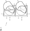
- a pedestrian signal generator 1 comprises an upper signal field 2S arranged one above the other for emitting a blocking signal and, below it, a lower signal field 2G for emitting an enabling signal.
- the blocking signal is represented by a red light signal with a symbol in the form of a standing pedestrian, and the enabling signal by a green light signal with a symbol in the form of a walking pedestrian.
- the symbol S of the standing pedestrian is shown surrounded by a solid line because it is currently illuminated, while the symbol G of the walking pedestrian is shown surrounded by a dashed line because it is not currently illuminated.
- Each signal field 2S, 2G comprises an outer housing 3 with a front housing door 4 in which a circular opening is provided for receiving a signal generator insert 5.
- the housing doors 4 can be attached to the Outer housing 3 can be hinged. For better visibility of the light signals, protruding chutes 6 are attached to the front doors 4 to shield from extraneous light.
- the optical attachment 14 has an internal Fresnel lens 15 and an external red or green diffuser 16.
- the edges of the front opening 8 of the inner housing 7, the Fresnel lens 15, and the diffuser 16 engage in a profile seal (not shown) that runs along the opening in the outer housing.
- Axial air ducts 17 are incorporated into the circumference of the Fresnel lens 15, allowing heated air to flow from an interior space enclosed by the inner housing 7 and the Fresnel lens 15 into a space enclosed by the Fresnel lens 15 and the diffuser 16.
- the pre-assembled signal generator insert 5 can be used by the manufacturer for a variety of different signal generators 1.
Landscapes
- Physics & Mathematics (AREA)
- General Physics & Mathematics (AREA)
- Traffic Control Systems (AREA)
- Illuminated Signs And Luminous Advertising (AREA)
Description
- Die Erfindung betrifft einen Signalgeber zur Abgabe eines Lichtsignals nach dem Oberbegriff des Patentanspruches 1.
- Lichtsignalanlagen dienen der Steuerung des Straßenverkehrs an einem Knotenpunkt des Straßennetzes, insbesondere an Kreuzungen oder Einmündungen. Sie umfassen an Masten oder Kettenwerken hängende Signalgeber zur Abgabe von Lichtsignalen an sich dem Knotenpunkt nähernde oder dort wartende Verkehrsteilnehmer, etwa an Führer von Kraftfahrzeugen oder Krafträdern aber auch an Radfahrer und Fußgänger. Ein Signalgeber weist ein oder mehrere aneinandergereihte Signalfelder auf, von welchen jedes ein Lichtzeichen abgeben kann. Häufig kommen dreifeldige Signalgeber vor, deren Signalfelder übereinander angeordnet sind. Dabei kann das obere Signalfeld ein rotes Lichtzeichen, das mittlere Signalfeld ein gelbes Lichtzeichen und das untere Signalfeld ein grünes Lichtzeichen abgeben. Die Dauer und Abfolge der abzugebenden Lichtsignale werden durch Ansteuerung einzelner oder mehrerer Signalfelder erzeugt, was gemäß einem in einem Steuergerät des Knotenpunktes ablaufenden Signalzeitenplan erfolgt.
- Ein Signalgeber der eingangs genannten Art ist beispielsweise aus der Offenlegungsschrift
DE 10 2014 205 453 A1 bekannt. Er umfasst ein topfförmiges Innengehäuse aus Kunststoff mit einer Frontöffnung. In dem Innengehäuse sind eine Lichtquelle mit wenigstens einer Leuchtdiode und eine Treiberbaugruppe zur Energieversorgung der Lichtquelle angeordnet. Die Frontöffnung wird durch einen Optikaufsatz zur Beeinflussung des von der Lichtquelle emittierten Lichtes verschlossen. Der Optikaufsatz weist eine innen liegende Fresnellinse und eine außen liegende Streuscheibe auf. Die Fresnellinse weist in einem optisch aktiven Bereich eine Reihe ringförmiger Stufen auf, bei deren Durchtritt von der punktförmigen Lichtquelle emittiertes Licht gebündelt wird. Die im optischen Pfad nachgeschaltete Streuscheibe ist farblos oder farbig und weist Waben-, Spinnweb- oder Prismenmuster auf, welches für eine gleichmäßige Lichtverteilung auf der Streuscheibe sorgt. Im Zwischenraum zwischen Fresnellinse und Streuscheibe kann eine Symbolmaske angeordnet sein. Die Symbolmaske dient der Darstellung eines Lichtzeichens mit einem Sinnbild und deckt ein Signalfeld bis auf das darzustellende Symbol ab, also zum Beispiel einen Fußgänger, stehend oder gehend, ein Fahrrad oder einen Pfeil, so dass das jeweilige Symbol dem Verkehrsteilnehmer bei geschaltetem Signalgeber durch hindurchtretendes Licht der Lichtquelle gegebenenfalls farbig angezeigt wird. - Bei dem bekannten Signalgeber ist die Frontöffnung des Innengehäuses durch den Optikaufsatz abdichtend verschlossen, um die herstellerseitig zu garantierenden Anforderungen an die Dichtheit gegen Eindringen von Feuchtigkeit und Schmutz zu erfüllten. Der Hersteller hat durch die große Typenvielfalt solcher Signalgeber - mit unterschiedlich großen Signalfeldern, farblosen oder unterschiedlich farbigen Streuscheiben, ohne Symbolmaske oder mit unterschiedlichen Symbolmasken, um nur einige zu nennen - einen großen logistischen Aufwand in der Produktion. Jeder dieser Signalgebertypen ist im Materialwirtschaftssystem unter einer eigenen Sachnummer zu führen. Ein weiterer Nachteil des bekannten Signalgebers ist es, dass bei einem Wechsel der Symbolmaske im Optikaufsatz der Signalgebereinsatz geöffnet werden muss, wobei Feuchtigkeit und Schmutz eindringen können.
- Aus
DE 20 2006 014 987 U1 ist ein Signalgeber zur Abgabe eines Lichtsignals für den Straßenverkehr bekannt, wobei der Signalgeber ein topfförmiges Innengehäuse mit einer Frontöffnung aufweist, in welchem eine Lichtquelle angeordnet ist. Es ist ein Optikaufsatz vorgesehen, der die Frontöffnung abdeckt und zur Beeinflussung des von der Lichtquelle emittierten Lichtes vorgesehen ist. Der Optikaufsatz weist eine innen liegende Fresnellinse und eine außen liegende Streuscheibe auf. Zudem ist zwischen der Fresnellinse und der Streuscheibe eine Symbolmaske vorgesehen, die das emittierte Licht teilweise abdeckt und ein Lichtzeichen mit einen Sinnbild darstellt. - Der Erfindung liegt daher die Aufgabe zugrunde, einen Signalgeber der eingangs genannten Art bereitzustellen, der die Nachteile des Standes der Technik überwindet.
- Die Aufgabe wird gelöst durch einen gattungsgemäßen Signalgeber mit den kennzeichnenden Merkmalen des Patentanspruches 1. Ein solcher Signalgeber ist zur Abgabe eines Lichtsignals für den Straßenverkehr ausgebildet und vorgesehen. Er umfasst ein topfförmiges Innengehäuse mit einer Frontöffnung. In dem Innengehäuse ist eine Lichtquelle angeordnet. Die Lichtquelle kann eine oder mehrere Leuchtdioden sowie eine Treiberbaugruppe zur Versorgung und Ansteuerung der Leuchtdioden aufweisen. Der Signalgeber umfasst ferner einen Optikaufsatz zur Beeinflussung des von der Lichtquelle emittierten Lichtes. Der Optikaufsatz deckt die Frontöffnung des Innengehäuses ab und weist eine innen liegende Fresnellinse und eine außen liegende Streuscheibe auf. Zur Darstellung eines Lichtzeichens mit Sinnbild weist der Signalgeber eine das emittierte Licht teilweise abdeckende Symbolmaske auf. Erfindungsgemäß bilden das Innengehäuse mit Lichtquelle und der Optikaufsatz einen vormontierten Signalgebereinsatz, bei dem der Optikaufsatz die Frontöffnung dichtend verschließt. Auf die Streuscheibe ist von außen eine die Symbolmaske aufweisende Abdeckung aufgesetzt. Hierdurch kann die Variantenzahl an Signalgebern stark eingeschränkt werden, da herstellerseitig nur die Typen an Signalgebereinsätzen mit einer transparenten Abdeckung zu führen ist. Die gewünschte Symbolmaske kann separat geliefert oder vor Ort im Feld bedarfsgerecht beschafft und montiert werden. Außerdem ist eine Montage und auch ein Wechsel der Symbolmaske ohne Öffnung des Innengehäuses des Signalgebereinsatzes möglich.
- Die Abdeckung weist eine transparente Schutzscheibe mit Befestigungsring und ein an der Schutzscheibe anliegendes und die Symbolmaske bildendes Einlegeteil auf. Die separat herstell- und lieferbare Symbolmaske kann so von innen an die Schutzscheibe gelegt werden. Diese aus zwei Komponenten bestehende Abdeckung wird dann mittels des Befestigungsrings am Signalgebereinsatz befestigt. Die Schutzscheibe hält die Symbolmaske und schützt sie vor äußeren Umwelteinflüssen, etwa vor Witterung, Verschmutzung oder Steinschlag. Schutzscheibe und Einlegeteil sind kongruent zur Streuscheibe und weißen übereinstimmende Wölbungen auf. Der Befestigungsring verläuft am kreisförmigen Umfang der Schutzscheibe und übergreift im montierten Zustand einen Bund der Streuscheibe, wo er beispielsweise durch einen Klemmsitz oder eine Rastverbindung fixiert wird.
- Der Befestigungsring umfasst im nachgerüsteten Zustand einen äußeren Rand der Streuscheibe und ist dort durch eine einfach lösbare Verbindung, etwa Klemmsitz oder Rastfedern, fixiert.
- In einer weiteren vorteilhaften Ausführungsform des erfindungsgemäßen Signalgebers ist das Einlegeteil als Spritzgussteil ausgebildet. Aufgrund der begrenzten Anzahl an unterschiedlichen Sinnbildern können durch die Bereitstellung von wenigen Gussformen bei einer hohen Stückzahl an Symbolmasken die Herstellkosten je Einlegeteil niedrig gehalten werden.
- In einer weiteren vorteilhaften Ausführungsform des erfindungsgemäßen Signalgebers ist das Einlegeteil als Kunststoffschale ausgebildet, aus der das darzustellende Symbol durch Fräsen oder durch Laserbehandlung herausgearbeitet ist. Die zugrunde liegende Kunststoffschale ist für jedes Sinnbild gleich und kann daher kostengünstig in großer Stückzahl hergestellt werden. Das jeweilige Sinnbild wird mittels programmierter Algorithmen, welche einen Fräskopf oder Laserstrahl einer Werkzeugmaschine ansteuern, computergestützt präzise und reproduzierbar hergestellt.
- In einer weiteren vorteilhaften Ausführungsform des erfindungsgemäßen Signalgebers ist das Einlegeteil als transparente Folie ausgebildet, welche unter Freilassung des Symbols mit schwarzer Farbe bedruckt ist. Das Symbol kann auf die Folie mittels Laser- oder Tintenstrahl gedruckt oder per Siebdruck aufgebracht werden. Durch Anwendung einer Drucktechnik bleibt es dem Hersteller einfach möglich, die Symbole flexibel zu gestalten.
- Weitere Vorteile und Eigenschaften der Erfindung ergeben sich aus nachfolgender Beschreibung eines Ausführungsbeispiels anhand der Zeichnungen, in deren
- FIG 1
- ein Signalgeber für Fußgänger mit zwei Signalfeldern in perspektivischer Ansicht,
- FIG 2
- einen Signalgebereinsatz für die beiden Signalfelder aus
FIG 1 in Explosionsdarstellung und - FIG 3
- den vormontierten Signalgebereinsatz aus
FIG 2 mit einer erfindungsgemäßen Abdeckung in Explosionsdarstellung - Gemäß
FIG 1 weist ein Signalgeber 1 für Fußgänger übereinander angeordnet ein oberes Signalfeld 2S zur Abgabe eines Sperrsignals und darunter ein unteres Signalfeld 2G zur Abgabe eines Freigabesignals auf. Das Sperrsignal wird durch ein rotes Lichtzeichen mit einem Sinnbild in Form eines stehenden Fußgängers, das Freigabesignal durch ein grünes Lichtzeichen mit einem Sinnbild in Form eines gehenden Fußgängers dargestellt. Das Symbol S des stehenden Fußgängers ist durch eine Volllinie umrandet dargestellt, da es gerade leuchtet, das Symbol G des gehenden Fußgängers ist, da gerade nicht leuchtend, durch eine Strichlinie umrandet dargestellt. Jedes Signalfeld 2S, 2G umfasst ein Außengehäuse 3 mit einer frontseitigen Gehäusetür 4, in welcher eine kreisrunde Öffnung zur Aufnahme eines Signalgebereinsatzes 5 vorgesehen ist. Die Gehäusetüren 4 können über seitlich angeordnete Scharniere am Außengehäuse 3 angelenkt sein. Für eine bessere Erkennbarkeit der Lichtzeichen sind von den Fronttüren 4 abstehende Schuten 6 zur Abschirmung von Fremdlicht angebracht. - Jeder Signalgebereinsatz 5 umfasst gemäß
FIG 2 ein topfförmiges Innengehäuse 7 mit einer Frontöffnung 8, welches in das Außengehäuse 2 hineinragt. Im Innengehäuses 7 ist eine Lichtquelle mit wenigstens einer Leuchtdiode 9 angeordnet. Die wenigstens eine Leuchtdiode 9 ist an einer Bodenwand 10 des Innengehäuses 5 angeordnet. Des Weiteren ist im Innengehäuse 7 eine Treiberbaugruppe 11 zur Energieversorgung der wenigstens einen Leuchtdiode 9 angeordnet, die an eine der schräg stehenden Seitenwände 12 des Innengehäuses 5 montiert ist. Bodenwand 10 und/oder Seitenwände 12 des Innengehäuses 7 sind innen wenigstens teilweise durch ein Kühlblech 13 ausgekleidet. Die Frontöffnung 8 des Innengehäuses 7 ist durch einen Optikaufsatz 14, der das von der Lichtquelle emittierte Licht beeinflusst, dichtend verschlossen. Der Optikaufsatz 14 weist eine innen liegende Fresnellinse 15 sowie eine außen liegende, rote oder grüne Streuscheibe 16 auf. In eine nicht dargestellte Profildichtung, die entlang der Öffnung im Außengehäuse verläuft, greifen die Ränder der Frontöffnung 8 des Innengehäuses 7, der Fresnellinse 15 und der Streuscheibe 16 ein. Am Umfang der Fresnellinse 15 sind axiale Luftkanäle 17 eingearbeitet, so dass erwärmte Luft aus einem von Innengehäuse 7 und Fresnellinse 15 umschlossenen Innenraum in einen von Fresnellinse 15 und Streuscheibe 16 umschlossenen Zwischenraum gelangen kann. Der so vormontierte Signalgebereinsatz 5 kann herstellerseitig für eine Vielzahl von unterschiedlichen Signalgebern 1 verwendet werden. - Der Signalgebereinsatz 5 wird nun zur Verwendung als oberes Signalfeld 2S eines Signalgebers 1 für Fußgänger gemäß
FIG 3 mit einer von außen auf die Streuscheibe 16 aufgesetzten Abdeckung 18 versehen. Die Abdeckung 18 ist zweikomponentig aufgebaut und weist eine transparente Schutzscheibe 19 mit Befestigungsring 20 und ein innen an der Schutzscheibe 19 anliegendes und die Symbolmaske bildendes Einlegeteil 21 auf. - Die Schutzscheibe 19 dient als Schutz der Symbolmaske 21 vor äußeren Einflüssen, wie Witterung oder Verschmutzung. Der Befestigungsring 20 umgreift im nachgerüsteten Zustand den äußeren Rand der Streuscheibe 16 und wird dort durch eine einfach lösbare Verbindung, etwa Klemmsitz oder Rastfedern, fixiert. Das Einlegeteil 21 kann als Spritzgussteil ausgebildet ist. Alternativ kann das Einlegeteil 21 auch als Kunststoffschale ausgebildet sein, aus der das Symbol S durch Fräsen oder durch Laserbehandlung herausgearbeitet ist. Ebenso kann das Einlegeteil 21 als transparente Folie ausgebildet sein, welche unter Freilassung des darzustellenden Symbols S mit schwarzer Farbe bedruckt ist. In jeder Alternative kann das die Symbolmaske bildende Einlegeteil 21 hinzugefügt, ausgetauscht oder gedreht werden, ohne dass dazu das Innengehäuse 7 geöffnet werden muss. Es genügt, die Schutzscheibe 16 der Abdeckung 14 abzunehmen, um an das Einlegeteil zu gelangen.
Claims (5)
- Signalgeber (1) zur Abgabe eines Lichtsignals für den Straßenverkehr, umfassend- ein topfförmiges Innengehäuse (7) mit einer Frontöffnung (8), in welchem eine Lichtquelle angeordnet ist,- einen die Frontöffnung (8) abdeckenden Optikaufsatz (14) zur Beeinflussung des von der Lichtquelle emittierten Lichtes, der eine innen liegende Fresnellinse (15) und eine außen liegende Streuscheibe (16) aufweist, und- eine das emittierte Licht teilweise abdeckende Symbolmaske (21) zur Darstellung eines Lichtzeichens mit Sinnbild (S, G),- wobei das Innengehäuse (7) mit Lichtquelle und der Optikaufsatz (14) einen vormontierten Signalgebereinsatz (5) bilden, bei dem der Optikaufsatz (14) die Frontöffnung (8) dichtend verschließt,dadurch gekennzeichnet,- dass eine die Symbolmaske (21) aufweisende Abdeckung (18) von außen auf die Streuscheibe (16) aufgesetzt ist,- wobei die Abdeckung (18) eine transparente Schutzscheibe (19) mit Befestigungsring (20) und ein an der Schutzscheibe (19) anliegendes und die Symbolmaske (21) bildendes Einlegeteil aufweist, und- wobei der Befestigungsring (20) im nachgerüsteten Zustand einen äußeren Rand der Streuscheibe (16) umfasst, und dort durch eine einfach lösbare Verbindung, etwa Klemmsitz oder Rastfedern, fixiert ist.
- Signalgeber (1) nach Anspruch 1,- wobei das Einlegeteil (21) als Spritzgussteil ausgebildet ist.
- Signalgeber (1) nach Anspruch 1,- wobei das Einlegeteil (21) als Kunststoffschale ausgebildet ist, aus der das Symbol (S, G) durch Fräsen oder durch Laserbehandlung herausgearbeitet ist.
- Signalgeber (1) nach Anspruch 1,- wobei das Einlegeteil (21) als transparente Folie ausgebildet ist, welche unter Freilassung des darzustellenden Symbols (S, G) mit schwarzer Farbe bedruckt ist.
- Signalgeber nach einem der vorhergehenden Ansprüche, wobei am Umfang der Fresnellinse (15) axiale Luftkanäle (17) eingearbeitet sind, so dass erwärmte Luft aus einem von dem Innengehäuse (7) und der Fresnellinse (15) umschlossenen Innenraum in einen von der Fresnellinse (15) und der Streuscheibe (16) umschlossenen Zwischenraum gelangen kann.
Applications Claiming Priority (1)
| Application Number | Priority Date | Filing Date | Title |
|---|---|---|---|
| DE102021211015.0A DE102021211015A1 (de) | 2021-09-30 | 2021-09-30 | Signalgeber zur Abgabe eines Lichtsignals |
Publications (2)
| Publication Number | Publication Date |
|---|---|
| EP4160570A1 EP4160570A1 (de) | 2023-04-05 |
| EP4160570B1 true EP4160570B1 (de) | 2025-07-02 |
Family
ID=83508459
Family Applications (1)
| Application Number | Title | Priority Date | Filing Date |
|---|---|---|---|
| EP22198942.9A Active EP4160570B1 (de) | 2021-09-30 | 2022-09-30 | Signalgeber zur abgabe eines lichtsignals |
Country Status (2)
| Country | Link |
|---|---|
| EP (1) | EP4160570B1 (de) |
| DE (1) | DE102021211015A1 (de) |
Family Cites Families (3)
| Publication number | Priority date | Publication date | Assignee | Title |
|---|---|---|---|---|
| US5485145A (en) * | 1991-03-11 | 1996-01-16 | Emergency Safety Products, Inc. | Electroluminescent sign conversion kit |
| DE202006014987U1 (de) | 2006-09-29 | 2006-12-14 | Siemens Ag | Signalleuchte |
| DE102014205453A1 (de) | 2014-03-24 | 2015-09-24 | Siemens Aktiengesellschaft | Signalgeber zur Abgabe eines Lichtsignals |
-
2021
- 2021-09-30 DE DE102021211015.0A patent/DE102021211015A1/de active Pending
-
2022
- 2022-09-30 EP EP22198942.9A patent/EP4160570B1/de active Active
Also Published As
| Publication number | Publication date |
|---|---|
| DE102021211015A1 (de) | 2023-03-30 |
| EP4160570A1 (de) | 2023-04-05 |
Similar Documents
| Publication | Publication Date | Title |
|---|---|---|
| EP3046804B1 (de) | Abdeckungseinrichtung, system, karosseriebauteil, karosseriebauteilsystem und fahrzeug | |
| EP0941892B1 (de) | Aussenrückblickspiegel für Fahrzeuge, vorzugsweise für Kraftfahrzeuge | |
| EP1914118B1 (de) | Aussenrückspiegel mit Leuchtmittel | |
| EP3825601B1 (de) | Lichtelement für ein kraftfahrzeug und kraftfahrzeug | |
| DE102004025385A1 (de) | Außenrückblickspiegel für Fahrzeuge, insbesondere Kraftfahrzeuge | |
| EP4313683B1 (de) | Baugruppe des leuchtenden kühlergrills | |
| DE102015107644A1 (de) | Signalleuchte für Fahrzeuge | |
| DE102014006567A1 (de) | Hinterleuchtetes Interieurbauteil | |
| EP3765782B1 (de) | Beleuchtungsvorrichtung für fahrzeuge | |
| DE10337617A1 (de) | Leuchtvorrichtung für Fahrzeuge | |
| DE102009055427B4 (de) | Kraftfahrzeuginnenverkleidungsteil mit Lichtquelle | |
| DE10337615B3 (de) | Leuchtvorrichtung für Fahrzeuge | |
| EP1859995B1 (de) | Außenspiegel eines Fahrzeugs | |
| DE102012211821A1 (de) | Leuchteneinheit für ein Kraftfahrzeug und Verfahren zum Herstellen eines Gehäuseelementes einer Leuchteneinheit für ein Kraftfahrzeug | |
| DE102007045412A1 (de) | Schildanordnung | |
| EP3792111B1 (de) | Leuchte | |
| EP4160570A1 (de) | Signalgeber zur abgabe eines lichtsignals | |
| DE69712440T2 (de) | Verkehrsampel mit Beleuchtungsvorrichtungen im Boden | |
| DE102017111322A1 (de) | Kommunikationsvorrichtung für ein Fahrzeug, insbesondere für ein autonomes oder teilautonomes Fahrzeug | |
| DE202004001269U1 (de) | Lichtabdeckung für einen Scheinwerfer eines Kraftfahrzeugs | |
| EP2927890B1 (de) | Signalgeber zur abgabe eines lichtsignals | |
| EP1597112B1 (de) | Aussenrückblickspiegel für kraftfahrzeuge | |
| DE202007004859U1 (de) | Anzeigeeinheit | |
| DE102019205859B4 (de) | Lautsprechereinheit | |
| DE102019203572B4 (de) | Fahrzeuganbauteil mit optionaler Beleuchtungseinrichtung |
Legal Events
| Date | Code | Title | Description |
|---|---|---|---|
| PUAI | Public reference made under article 153(3) epc to a published international application that has entered the european phase |
Free format text: ORIGINAL CODE: 0009012 |
|
| STAA | Information on the status of an ep patent application or granted ep patent |
Free format text: STATUS: THE APPLICATION HAS BEEN PUBLISHED |
|
| AK | Designated contracting states |
Kind code of ref document: A1 Designated state(s): AL AT BE BG CH CY CZ DE DK EE ES FI FR GB GR HR HU IE IS IT LI LT LU LV MC MK MT NL NO PL PT RO RS SE SI SK SM TR |
|
| STAA | Information on the status of an ep patent application or granted ep patent |
Free format text: STATUS: REQUEST FOR EXAMINATION WAS MADE |
|
| 17P | Request for examination filed |
Effective date: 20231005 |
|
| RBV | Designated contracting states (corrected) |
Designated state(s): AL AT BE BG CH CY CZ DE DK EE ES FI FR GB GR HR HU IE IS IT LI LT LU LV MC MK MT NL NO PL PT RO RS SE SI SK SM TR |
|
| GRAP | Despatch of communication of intention to grant a patent |
Free format text: ORIGINAL CODE: EPIDOSNIGR1 |
|
| STAA | Information on the status of an ep patent application or granted ep patent |
Free format text: STATUS: GRANT OF PATENT IS INTENDED |
|
| INTG | Intention to grant announced |
Effective date: 20250130 |
|
| GRAS | Grant fee paid |
Free format text: ORIGINAL CODE: EPIDOSNIGR3 |
|
| GRAA | (expected) grant |
Free format text: ORIGINAL CODE: 0009210 |
|
| STAA | Information on the status of an ep patent application or granted ep patent |
Free format text: STATUS: THE PATENT HAS BEEN GRANTED |
|
| AK | Designated contracting states |
Kind code of ref document: B1 Designated state(s): AL AT BE BG CH CY CZ DE DK EE ES FI FR GB GR HR HU IE IS IT LI LT LU LV MC MK MT NL NO PL PT RO RS SE SI SK SM TR |
|
| REG | Reference to a national code |
Ref country code: GB Ref legal event code: FG4D Free format text: NOT ENGLISH |
|
| REG | Reference to a national code |
Ref country code: CH Ref legal event code: EP |
|
| REG | Reference to a national code |
Ref country code: DE Ref legal event code: R096 Ref document number: 502022004481 Country of ref document: DE |
|
| REG | Reference to a national code |
Ref country code: IE Ref legal event code: FG4D Free format text: LANGUAGE OF EP DOCUMENT: GERMAN |
|
| PGFP | Annual fee paid to national office [announced via postgrant information from national office to epo] |
Ref country code: DE Payment date: 20250701 Year of fee payment: 4 |
|
| REG | Reference to a national code |
Ref country code: NL Ref legal event code: MP Effective date: 20250702 |
|
| PG25 | Lapsed in a contracting state [announced via postgrant information from national office to epo] |
Ref country code: PT Free format text: LAPSE BECAUSE OF FAILURE TO SUBMIT A TRANSLATION OF THE DESCRIPTION OR TO PAY THE FEE WITHIN THE PRESCRIBED TIME-LIMIT Effective date: 20251103 |
|
| PG25 | Lapsed in a contracting state [announced via postgrant information from national office to epo] |
Ref country code: NL Free format text: LAPSE BECAUSE OF FAILURE TO SUBMIT A TRANSLATION OF THE DESCRIPTION OR TO PAY THE FEE WITHIN THE PRESCRIBED TIME-LIMIT Effective date: 20250702 |
|
| PG25 | Lapsed in a contracting state [announced via postgrant information from national office to epo] |
Ref country code: IS Free format text: LAPSE BECAUSE OF FAILURE TO SUBMIT A TRANSLATION OF THE DESCRIPTION OR TO PAY THE FEE WITHIN THE PRESCRIBED TIME-LIMIT Effective date: 20251102 |
|
| PG25 | Lapsed in a contracting state [announced via postgrant information from national office to epo] |
Ref country code: NO Free format text: LAPSE BECAUSE OF FAILURE TO SUBMIT A TRANSLATION OF THE DESCRIPTION OR TO PAY THE FEE WITHIN THE PRESCRIBED TIME-LIMIT Effective date: 20251002 |
|
| REG | Reference to a national code |
Ref country code: LT Ref legal event code: MG9D |
|
| PG25 | Lapsed in a contracting state [announced via postgrant information from national office to epo] |
Ref country code: FI Free format text: LAPSE BECAUSE OF FAILURE TO SUBMIT A TRANSLATION OF THE DESCRIPTION OR TO PAY THE FEE WITHIN THE PRESCRIBED TIME-LIMIT Effective date: 20250702 |
|
| PG25 | Lapsed in a contracting state [announced via postgrant information from national office to epo] |
Ref country code: HR Free format text: LAPSE BECAUSE OF FAILURE TO SUBMIT A TRANSLATION OF THE DESCRIPTION OR TO PAY THE FEE WITHIN THE PRESCRIBED TIME-LIMIT Effective date: 20250702 |
|
| PG25 | Lapsed in a contracting state [announced via postgrant information from national office to epo] |
Ref country code: GR Free format text: LAPSE BECAUSE OF FAILURE TO SUBMIT A TRANSLATION OF THE DESCRIPTION OR TO PAY THE FEE WITHIN THE PRESCRIBED TIME-LIMIT Effective date: 20251003 |
|
| PG25 | Lapsed in a contracting state [announced via postgrant information from national office to epo] |
Ref country code: SE Free format text: LAPSE BECAUSE OF FAILURE TO SUBMIT A TRANSLATION OF THE DESCRIPTION OR TO PAY THE FEE WITHIN THE PRESCRIBED TIME-LIMIT Effective date: 20250702 Ref country code: CZ Free format text: LAPSE BECAUSE OF FAILURE TO SUBMIT A TRANSLATION OF THE DESCRIPTION OR TO PAY THE FEE WITHIN THE PRESCRIBED TIME-LIMIT Effective date: 20250702 |
|
| PG25 | Lapsed in a contracting state [announced via postgrant information from national office to epo] |
Ref country code: LV Free format text: LAPSE BECAUSE OF FAILURE TO SUBMIT A TRANSLATION OF THE DESCRIPTION OR TO PAY THE FEE WITHIN THE PRESCRIBED TIME-LIMIT Effective date: 20250702 |
|
| PG25 | Lapsed in a contracting state [announced via postgrant information from national office to epo] |
Ref country code: BG Free format text: LAPSE BECAUSE OF FAILURE TO SUBMIT A TRANSLATION OF THE DESCRIPTION OR TO PAY THE FEE WITHIN THE PRESCRIBED TIME-LIMIT Effective date: 20250702 Ref country code: PL Free format text: LAPSE BECAUSE OF FAILURE TO SUBMIT A TRANSLATION OF THE DESCRIPTION OR TO PAY THE FEE WITHIN THE PRESCRIBED TIME-LIMIT Effective date: 20250702 |
|
| PG25 | Lapsed in a contracting state [announced via postgrant information from national office to epo] |
Ref country code: RS Free format text: LAPSE BECAUSE OF FAILURE TO SUBMIT A TRANSLATION OF THE DESCRIPTION OR TO PAY THE FEE WITHIN THE PRESCRIBED TIME-LIMIT Effective date: 20251002 |
|
| PG25 | Lapsed in a contracting state [announced via postgrant information from national office to epo] |
Ref country code: ES Free format text: LAPSE BECAUSE OF FAILURE TO SUBMIT A TRANSLATION OF THE DESCRIPTION OR TO PAY THE FEE WITHIN THE PRESCRIBED TIME-LIMIT Effective date: 20250702 |
|
| PG25 | Lapsed in a contracting state [announced via postgrant information from national office to epo] |
Ref country code: RO Free format text: LAPSE BECAUSE OF FAILURE TO SUBMIT A TRANSLATION OF THE DESCRIPTION OR TO PAY THE FEE WITHIN THE PRESCRIBED TIME-LIMIT Effective date: 20250702 |
|
| PG25 | Lapsed in a contracting state [announced via postgrant information from national office to epo] |
Ref country code: SM Free format text: LAPSE BECAUSE OF FAILURE TO SUBMIT A TRANSLATION OF THE DESCRIPTION OR TO PAY THE FEE WITHIN THE PRESCRIBED TIME-LIMIT Effective date: 20250702 |
|
| REG | Reference to a national code |
Ref country code: DE Ref legal event code: R097 Ref document number: 502022004481 Country of ref document: DE |
|
| PG25 | Lapsed in a contracting state [announced via postgrant information from national office to epo] |
Ref country code: DK Free format text: LAPSE BECAUSE OF FAILURE TO SUBMIT A TRANSLATION OF THE DESCRIPTION OR TO PAY THE FEE WITHIN THE PRESCRIBED TIME-LIMIT Effective date: 20250702 |
|
| PG25 | Lapsed in a contracting state [announced via postgrant information from national office to epo] |
Ref country code: IT Free format text: LAPSE BECAUSE OF FAILURE TO SUBMIT A TRANSLATION OF THE DESCRIPTION OR TO PAY THE FEE WITHIN THE PRESCRIBED TIME-LIMIT Effective date: 20250702 |
|
| REG | Reference to a national code |
Ref country code: CH Ref legal event code: H13 Free format text: ST27 STATUS EVENT CODE: U-0-0-H10-H13 (AS PROVIDED BY THE NATIONAL OFFICE) Effective date: 20260425 |
|
| PG25 | Lapsed in a contracting state [announced via postgrant information from national office to epo] |
Ref country code: SK Free format text: LAPSE BECAUSE OF FAILURE TO SUBMIT A TRANSLATION OF THE DESCRIPTION OR TO PAY THE FEE WITHIN THE PRESCRIBED TIME-LIMIT Effective date: 20250702 Ref country code: EE Free format text: LAPSE BECAUSE OF FAILURE TO SUBMIT A TRANSLATION OF THE DESCRIPTION OR TO PAY THE FEE WITHIN THE PRESCRIBED TIME-LIMIT Effective date: 20250702 |
|
| PLBE | No opposition filed within time limit |
Free format text: ORIGINAL CODE: 0009261 |
|
| STAA | Information on the status of an ep patent application or granted ep patent |
Free format text: STATUS: NO OPPOSITION FILED WITHIN TIME LIMIT |
|
| PG25 | Lapsed in a contracting state [announced via postgrant information from national office to epo] |
Ref country code: LU Free format text: LAPSE BECAUSE OF NON-PAYMENT OF DUE FEES Effective date: 20250930 |
|
| REG | Reference to a national code |
Ref country code: CH Ref legal event code: L10 Free format text: ST27 STATUS EVENT CODE: U-0-0-L10-L00 (AS PROVIDED BY THE NATIONAL OFFICE) Effective date: 20260518 |
|
| REG | Reference to a national code |
Ref country code: BE Ref legal event code: MM Effective date: 20250930 |
|
| 26N | No opposition filed |
Effective date: 20260407 |
|
| PG25 | Lapsed in a contracting state [announced via postgrant information from national office to epo] |
Ref country code: MC Free format text: LAPSE BECAUSE OF FAILURE TO SUBMIT A TRANSLATION OF THE DESCRIPTION OR TO PAY THE FEE WITHIN THE PRESCRIBED TIME-LIMIT Effective date: 20250702 Ref country code: LT Free format text: LAPSE BECAUSE OF FAILURE TO SUBMIT A TRANSLATION OF THE DESCRIPTION OR TO PAY THE FEE WITHIN THE PRESCRIBED TIME-LIMIT Effective date: 20250702 |
|
| PG25 | Lapsed in a contracting state [announced via postgrant information from national office to epo] |
Ref country code: BE Free format text: LAPSE BECAUSE OF NON-PAYMENT OF DUE FEES Effective date: 20250930 Ref country code: CH Free format text: LAPSE BECAUSE OF NON-PAYMENT OF DUE FEES Effective date: 20250930 Ref country code: IE Free format text: LAPSE BECAUSE OF NON-PAYMENT OF DUE FEES Effective date: 20250930 |
|
| PG25 | Lapsed in a contracting state [announced via postgrant information from national office to epo] |
Ref country code: FR Free format text: LAPSE BECAUSE OF NON-PAYMENT OF DUE FEES Effective date: 20250930 |