EP4160271B1 - Verfahren und vorrichtung zur verarbeitung von daten für ein autonomes fahrzeug, elektronische vorrichtung und speichermedium - Google Patents
Verfahren und vorrichtung zur verarbeitung von daten für ein autonomes fahrzeug, elektronische vorrichtung und speichermedium Download PDFInfo
- Publication number
- EP4160271B1 EP4160271B1 EP22204106.3A EP22204106A EP4160271B1 EP 4160271 B1 EP4160271 B1 EP 4160271B1 EP 22204106 A EP22204106 A EP 22204106A EP 4160271 B1 EP4160271 B1 EP 4160271B1
- Authority
- EP
- European Patent Office
- Prior art keywords
- data
- inertial measurement
- projection
- relative pose
- determining
- Prior art date
- Legal status (The legal status is an assumption and is not a legal conclusion. Google has not performed a legal analysis and makes no representation as to the accuracy of the status listed.)
- Active
Links
Images


Classifications
-
- B—PERFORMING OPERATIONS; TRANSPORTING
- B60—VEHICLES IN GENERAL
- B60W—CONJOINT CONTROL OF VEHICLE SUB-UNITS OF DIFFERENT TYPE OR DIFFERENT FUNCTION; CONTROL SYSTEMS SPECIALLY ADAPTED FOR HYBRID VEHICLES; ROAD VEHICLE DRIVE CONTROL SYSTEMS FOR PURPOSES NOT RELATED TO THE CONTROL OF A PARTICULAR SUB-UNIT
- B60W60/00—Drive control systems specially adapted for autonomous road vehicles
- B60W60/001—Planning or execution of driving tasks
-
- B—PERFORMING OPERATIONS; TRANSPORTING
- B60—VEHICLES IN GENERAL
- B60W—CONJOINT CONTROL OF VEHICLE SUB-UNITS OF DIFFERENT TYPE OR DIFFERENT FUNCTION; CONTROL SYSTEMS SPECIALLY ADAPTED FOR HYBRID VEHICLES; ROAD VEHICLE DRIVE CONTROL SYSTEMS FOR PURPOSES NOT RELATED TO THE CONTROL OF A PARTICULAR SUB-UNIT
- B60W40/00—Estimation or calculation of non-directly measurable driving parameters for road vehicle drive control systems not related to the control of a particular sub unit, e.g. by using mathematical models
- B60W40/10—Estimation or calculation of non-directly measurable driving parameters for road vehicle drive control systems not related to the control of a particular sub unit, e.g. by using mathematical models related to vehicle motion
-
- G—PHYSICS
- G01—MEASURING; TESTING
- G01C—MEASURING DISTANCES, LEVELS OR BEARINGS; SURVEYING; NAVIGATION; GYROSCOPIC INSTRUMENTS; PHOTOGRAMMETRY OR VIDEOGRAMMETRY
- G01C21/00—Navigation; Navigational instruments not provided for in groups G01C1/00 - G01C19/00
- G01C21/26—Navigation; Navigational instruments not provided for in groups G01C1/00 - G01C19/00 specially adapted for navigation in a road network
- G01C21/28—Navigation; Navigational instruments not provided for in groups G01C1/00 - G01C19/00 specially adapted for navigation in a road network with correlation of data from several navigational instruments
-
- B—PERFORMING OPERATIONS; TRANSPORTING
- B60—VEHICLES IN GENERAL
- B60W—CONJOINT CONTROL OF VEHICLE SUB-UNITS OF DIFFERENT TYPE OR DIFFERENT FUNCTION; CONTROL SYSTEMS SPECIALLY ADAPTED FOR HYBRID VEHICLES; ROAD VEHICLE DRIVE CONTROL SYSTEMS FOR PURPOSES NOT RELATED TO THE CONTROL OF A PARTICULAR SUB-UNIT
- B60W50/00—Details of control systems for road vehicle drive control not related to the control of a particular sub-unit, e.g. process diagnostic or vehicle driver interfaces
-
- B—PERFORMING OPERATIONS; TRANSPORTING
- B60—VEHICLES IN GENERAL
- B60K—ARRANGEMENT OR MOUNTING OF PROPULSION UNITS OR OF TRANSMISSIONS IN VEHICLES; ARRANGEMENT OR MOUNTING OF PLURAL DIVERSE PRIME-MOVERS IN VEHICLES; AUXILIARY DRIVES FOR VEHICLES; INSTRUMENTATION OR DASHBOARDS FOR VEHICLES; ARRANGEMENTS IN CONNECTION WITH COOLING, AIR INTAKE, GAS EXHAUST OR FUEL SUPPLY OF PROPULSION UNITS IN VEHICLES
- B60K35/00—Instruments specially adapted for vehicles; Arrangement of instruments in or on vehicles
- B60K35/10—Input arrangements, i.e. from user to vehicle, associated with vehicle functions or specially adapted therefor
-
- B—PERFORMING OPERATIONS; TRANSPORTING
- B60—VEHICLES IN GENERAL
- B60K—ARRANGEMENT OR MOUNTING OF PROPULSION UNITS OR OF TRANSMISSIONS IN VEHICLES; ARRANGEMENT OR MOUNTING OF PLURAL DIVERSE PRIME-MOVERS IN VEHICLES; AUXILIARY DRIVES FOR VEHICLES; INSTRUMENTATION OR DASHBOARDS FOR VEHICLES; ARRANGEMENTS IN CONNECTION WITH COOLING, AIR INTAKE, GAS EXHAUST OR FUEL SUPPLY OF PROPULSION UNITS IN VEHICLES
- B60K35/00—Instruments specially adapted for vehicles; Arrangement of instruments in or on vehicles
- B60K35/20—Output arrangements, i.e. from vehicle to user, associated with vehicle functions or specially adapted therefor
- B60K35/21—Output arrangements, i.e. from vehicle to user, associated with vehicle functions or specially adapted therefor using visual output, e.g. blinking lights or matrix displays
- B60K35/22—Display screens
-
- B—PERFORMING OPERATIONS; TRANSPORTING
- B60—VEHICLES IN GENERAL
- B60K—ARRANGEMENT OR MOUNTING OF PROPULSION UNITS OR OF TRANSMISSIONS IN VEHICLES; ARRANGEMENT OR MOUNTING OF PLURAL DIVERSE PRIME-MOVERS IN VEHICLES; AUXILIARY DRIVES FOR VEHICLES; INSTRUMENTATION OR DASHBOARDS FOR VEHICLES; ARRANGEMENTS IN CONNECTION WITH COOLING, AIR INTAKE, GAS EXHAUST OR FUEL SUPPLY OF PROPULSION UNITS IN VEHICLES
- B60K35/00—Instruments specially adapted for vehicles; Arrangement of instruments in or on vehicles
- B60K35/20—Output arrangements, i.e. from vehicle to user, associated with vehicle functions or specially adapted therefor
- B60K35/28—Output arrangements, i.e. from vehicle to user, associated with vehicle functions or specially adapted therefor characterised by the type of the output information, e.g. video entertainment or vehicle dynamics information; characterised by the purpose of the output information, e.g. for attracting the attention of the driver
-
- B—PERFORMING OPERATIONS; TRANSPORTING
- B60—VEHICLES IN GENERAL
- B60W—CONJOINT CONTROL OF VEHICLE SUB-UNITS OF DIFFERENT TYPE OR DIFFERENT FUNCTION; CONTROL SYSTEMS SPECIALLY ADAPTED FOR HYBRID VEHICLES; ROAD VEHICLE DRIVE CONTROL SYSTEMS FOR PURPOSES NOT RELATED TO THE CONTROL OF A PARTICULAR SUB-UNIT
- B60W40/00—Estimation or calculation of non-directly measurable driving parameters for road vehicle drive control systems not related to the control of a particular sub unit, e.g. by using mathematical models
- B60W40/02—Estimation or calculation of non-directly measurable driving parameters for road vehicle drive control systems not related to the control of a particular sub unit, e.g. by using mathematical models related to ambient conditions
-
- B—PERFORMING OPERATIONS; TRANSPORTING
- B60—VEHICLES IN GENERAL
- B60W—CONJOINT CONTROL OF VEHICLE SUB-UNITS OF DIFFERENT TYPE OR DIFFERENT FUNCTION; CONTROL SYSTEMS SPECIALLY ADAPTED FOR HYBRID VEHICLES; ROAD VEHICLE DRIVE CONTROL SYSTEMS FOR PURPOSES NOT RELATED TO THE CONTROL OF A PARTICULAR SUB-UNIT
- B60W60/00—Drive control systems specially adapted for autonomous road vehicles
-
- G—PHYSICS
- G01—MEASURING; TESTING
- G01C—MEASURING DISTANCES, LEVELS OR BEARINGS; SURVEYING; NAVIGATION; GYROSCOPIC INSTRUMENTS; PHOTOGRAMMETRY OR VIDEOGRAMMETRY
- G01C21/00—Navigation; Navigational instruments not provided for in groups G01C1/00 - G01C19/00
- G01C21/10—Navigation; Navigational instruments not provided for in groups G01C1/00 - G01C19/00 by using measurements of speed or acceleration
- G01C21/12—Navigation; Navigational instruments not provided for in groups G01C1/00 - G01C19/00 by using measurements of speed or acceleration executed aboard the object being navigated; Dead reckoning
- G01C21/16—Navigation; Navigational instruments not provided for in groups G01C1/00 - G01C19/00 by using measurements of speed or acceleration executed aboard the object being navigated; Dead reckoning by integrating acceleration or speed, i.e. inertial navigation
- G01C21/165—Navigation; Navigational instruments not provided for in groups G01C1/00 - G01C19/00 by using measurements of speed or acceleration executed aboard the object being navigated; Dead reckoning by integrating acceleration or speed, i.e. inertial navigation combined with non-inertial navigation instruments
-
- G—PHYSICS
- G01—MEASURING; TESTING
- G01S—RADIO DIRECTION-FINDING; RADIO NAVIGATION; DETERMINING DISTANCE OR VELOCITY BY USE OF RADIO WAVES; LOCATING OR PRESENCE-DETECTING BY USE OF THE REFLECTION OR RERADIATION OF RADIO WAVES; ANALOGOUS ARRANGEMENTS USING OTHER WAVES
- G01S17/00—Systems using the reflection or reradiation of electromagnetic waves other than radio waves, e.g. lidar systems
- G01S17/86—Combinations of lidar systems with systems other than lidar, radar or sonar, e.g. with direction finders
-
- G—PHYSICS
- G01—MEASURING; TESTING
- G01S—RADIO DIRECTION-FINDING; RADIO NAVIGATION; DETERMINING DISTANCE OR VELOCITY BY USE OF RADIO WAVES; LOCATING OR PRESENCE-DETECTING BY USE OF THE REFLECTION OR RERADIATION OF RADIO WAVES; ANALOGOUS ARRANGEMENTS USING OTHER WAVES
- G01S17/00—Systems using the reflection or reradiation of electromagnetic waves other than radio waves, e.g. lidar systems
- G01S17/88—Lidar systems specially adapted for specific applications
- G01S17/89—Lidar systems specially adapted for specific applications for mapping or imaging
-
- G—PHYSICS
- G01—MEASURING; TESTING
- G01S—RADIO DIRECTION-FINDING; RADIO NAVIGATION; DETERMINING DISTANCE OR VELOCITY BY USE OF RADIO WAVES; LOCATING OR PRESENCE-DETECTING BY USE OF THE REFLECTION OR RERADIATION OF RADIO WAVES; ANALOGOUS ARRANGEMENTS USING OTHER WAVES
- G01S17/00—Systems using the reflection or reradiation of electromagnetic waves other than radio waves, e.g. lidar systems
- G01S17/88—Lidar systems specially adapted for specific applications
- G01S17/93—Lidar systems specially adapted for specific applications for anti-collision purposes
-
- G—PHYSICS
- G01—MEASURING; TESTING
- G01S—RADIO DIRECTION-FINDING; RADIO NAVIGATION; DETERMINING DISTANCE OR VELOCITY BY USE OF RADIO WAVES; LOCATING OR PRESENCE-DETECTING BY USE OF THE REFLECTION OR RERADIATION OF RADIO WAVES; ANALOGOUS ARRANGEMENTS USING OTHER WAVES
- G01S7/00—Details of systems according to groups G01S13/00, G01S15/00, G01S17/00
- G01S7/48—Details of systems according to groups G01S13/00, G01S15/00, G01S17/00 of systems according to group G01S17/00
- G01S7/4808—Evaluating distance, position or velocity data
-
- G—PHYSICS
- G06—COMPUTING OR CALCULATING; COUNTING
- G06T—IMAGE DATA PROCESSING OR GENERATION, IN GENERAL
- G06T7/00—Image analysis
- G06T7/20—Analysis of motion
- G06T7/246—Analysis of motion using feature-based methods, e.g. the tracking of corners or segments
-
- G—PHYSICS
- G06—COMPUTING OR CALCULATING; COUNTING
- G06T—IMAGE DATA PROCESSING OR GENERATION, IN GENERAL
- G06T7/00—Image analysis
- G06T7/50—Depth or shape recovery
-
- G—PHYSICS
- G06—COMPUTING OR CALCULATING; COUNTING
- G06T—IMAGE DATA PROCESSING OR GENERATION, IN GENERAL
- G06T7/00—Image analysis
- G06T7/70—Determining position or orientation of objects or cameras
- G06T7/73—Determining position or orientation of objects or cameras using feature-based methods
-
- B—PERFORMING OPERATIONS; TRANSPORTING
- B60—VEHICLES IN GENERAL
- B60W—CONJOINT CONTROL OF VEHICLE SUB-UNITS OF DIFFERENT TYPE OR DIFFERENT FUNCTION; CONTROL SYSTEMS SPECIALLY ADAPTED FOR HYBRID VEHICLES; ROAD VEHICLE DRIVE CONTROL SYSTEMS FOR PURPOSES NOT RELATED TO THE CONTROL OF A PARTICULAR SUB-UNIT
- B60W50/00—Details of control systems for road vehicle drive control not related to the control of a particular sub-unit, e.g. process diagnostic or vehicle driver interfaces
- B60W2050/0001—Details of the control system
- B60W2050/0002—Automatic control, details of type of controller or control system architecture
- B60W2050/0004—In digital systems, e.g. discrete-time systems involving sampling
- B60W2050/0005—Processor details or data handling, e.g. memory registers or chip architecture
-
- B—PERFORMING OPERATIONS; TRANSPORTING
- B60—VEHICLES IN GENERAL
- B60W—CONJOINT CONTROL OF VEHICLE SUB-UNITS OF DIFFERENT TYPE OR DIFFERENT FUNCTION; CONTROL SYSTEMS SPECIALLY ADAPTED FOR HYBRID VEHICLES; ROAD VEHICLE DRIVE CONTROL SYSTEMS FOR PURPOSES NOT RELATED TO THE CONTROL OF A PARTICULAR SUB-UNIT
- B60W50/00—Details of control systems for road vehicle drive control not related to the control of a particular sub-unit, e.g. process diagnostic or vehicle driver interfaces
- B60W2050/0001—Details of the control system
- B60W2050/0043—Signal treatments, identification of variables or parameters, parameter estimation or state estimation
-
- B—PERFORMING OPERATIONS; TRANSPORTING
- B60—VEHICLES IN GENERAL
- B60W—CONJOINT CONTROL OF VEHICLE SUB-UNITS OF DIFFERENT TYPE OR DIFFERENT FUNCTION; CONTROL SYSTEMS SPECIALLY ADAPTED FOR HYBRID VEHICLES; ROAD VEHICLE DRIVE CONTROL SYSTEMS FOR PURPOSES NOT RELATED TO THE CONTROL OF A PARTICULAR SUB-UNIT
- B60W50/00—Details of control systems for road vehicle drive control not related to the control of a particular sub-unit, e.g. process diagnostic or vehicle driver interfaces
- B60W2050/0062—Adapting control system settings
- B60W2050/0075—Automatic parameter input, automatic initialising or calibrating means
- B60W2050/0083—Setting, resetting, calibration
-
- B—PERFORMING OPERATIONS; TRANSPORTING
- B60—VEHICLES IN GENERAL
- B60W—CONJOINT CONTROL OF VEHICLE SUB-UNITS OF DIFFERENT TYPE OR DIFFERENT FUNCTION; CONTROL SYSTEMS SPECIALLY ADAPTED FOR HYBRID VEHICLES; ROAD VEHICLE DRIVE CONTROL SYSTEMS FOR PURPOSES NOT RELATED TO THE CONTROL OF A PARTICULAR SUB-UNIT
- B60W2420/00—Indexing codes relating to the type of sensors based on the principle of their operation
- B60W2420/40—Photo, light or radio wave sensitive means, e.g. infrared sensors
- B60W2420/403—Image sensing, e.g. optical camera
-
- B—PERFORMING OPERATIONS; TRANSPORTING
- B60—VEHICLES IN GENERAL
- B60W—CONJOINT CONTROL OF VEHICLE SUB-UNITS OF DIFFERENT TYPE OR DIFFERENT FUNCTION; CONTROL SYSTEMS SPECIALLY ADAPTED FOR HYBRID VEHICLES; ROAD VEHICLE DRIVE CONTROL SYSTEMS FOR PURPOSES NOT RELATED TO THE CONTROL OF A PARTICULAR SUB-UNIT
- B60W2420/00—Indexing codes relating to the type of sensors based on the principle of their operation
- B60W2420/40—Photo, light or radio wave sensitive means, e.g. infrared sensors
- B60W2420/408—Radar; Laser, e.g. lidar
-
- B—PERFORMING OPERATIONS; TRANSPORTING
- B60—VEHICLES IN GENERAL
- B60W—CONJOINT CONTROL OF VEHICLE SUB-UNITS OF DIFFERENT TYPE OR DIFFERENT FUNCTION; CONTROL SYSTEMS SPECIALLY ADAPTED FOR HYBRID VEHICLES; ROAD VEHICLE DRIVE CONTROL SYSTEMS FOR PURPOSES NOT RELATED TO THE CONTROL OF A PARTICULAR SUB-UNIT
- B60W2556/00—Input parameters relating to data
- B60W2556/35—Data fusion
-
- G—PHYSICS
- G01—MEASURING; TESTING
- G01S—RADIO DIRECTION-FINDING; RADIO NAVIGATION; DETERMINING DISTANCE OR VELOCITY BY USE OF RADIO WAVES; LOCATING OR PRESENCE-DETECTING BY USE OF THE REFLECTION OR RERADIATION OF RADIO WAVES; ANALOGOUS ARRANGEMENTS USING OTHER WAVES
- G01S5/00—Position-fixing by co-ordinating two or more direction or position line determinations; Position-fixing by co-ordinating two or more distance determinations
- G01S5/16—Position-fixing by co-ordinating two or more direction or position line determinations; Position-fixing by co-ordinating two or more distance determinations using electromagnetic waves other than radio waves
-
- G—PHYSICS
- G06—COMPUTING OR CALCULATING; COUNTING
- G06T—IMAGE DATA PROCESSING OR GENERATION, IN GENERAL
- G06T2207/00—Indexing scheme for image analysis or image enhancement
- G06T2207/10—Image acquisition modality
- G06T2207/10028—Range image; Depth image; 3D point clouds
-
- G—PHYSICS
- G06—COMPUTING OR CALCULATING; COUNTING
- G06T—IMAGE DATA PROCESSING OR GENERATION, IN GENERAL
- G06T2207/00—Indexing scheme for image analysis or image enhancement
- G06T2207/10—Image acquisition modality
- G06T2207/10032—Satellite or aerial image; Remote sensing
- G06T2207/10044—Radar image
Definitions
- the present disclosure relates to a field of an intelligent transportation technology, in particular to a field of autonomous driving. More specifically, the present disclosure relates to a method and apparatus for processing data for an autonomous vehicle, an electronic device, a storage medium, and a program product.
- CN112598757A discloses a multi-sensor time-space calibration method, including: obtaining IMU data through an IMU sensor, obtaining image data through a camera, and obtaining point cloud data through a laser radar; carrying out semantic segmentation and feature point extraction on the image data, carrying out matching, constructing a re-projection error equation, and introducing first time deviation between an IMU sensor and a camera into the re-projection error equation; correcting the point cloud data, introducing a second time deviation between the IMU sensor and the laser radar, registering the corrected point cloud, and calculating a relative pose between two frames of point clouds; obtaining IMU data between two frames of images and IMU data between point clouds, and calculating a relative pose and a pose deviation through pre-integration; and setting a sliding window, and performing iterative optimization solution according to the reprojection error equation, the relative pose and the pose deviation in the sliding window to realize multi-sensor time-space calibration.
- the present disclosure provides a method for processing data for an autonomous vehicle, an electronic device, a storage medium, and a program product.
- the invention is defined by the appended claims.
- Positioning calculation using a visual/LiDAR odometry usually consumes a lot of CPU computing resources in a process of. Therefore, it is useful in practice to build an odometry based on vision, LiDAR and inertial measurement units, which has a high precision, a low usage of CPU resources, and a reasonable utilization of GPU resources.
- Embodiments of the present disclosure provide a method of building an odometry based on vision, LiDAR and inertial measurement units, and positioning an autonomous vehicle by using the odometry based on vision, LiDAR and inertial measurement units.
- ( ⁇ ) w represents a global coordinate system, that is, an IMU (inertial measurement unit) coordinate system corresponding to an initial key frame of a system.
- ( ⁇ ) b represents a local coordinate system, that is, an IMU coordinate system.
- ( ⁇ ) c represents a visual coordinate system.
- a rotation matrix R and a Hamilton-style unit quaternion q herein are used to express a rotation.
- q b w and p b w represent a rotation value and a translation value from the local coordinate system to the global coordinate system.
- R veh b and t veh b represent an external parameter relationship from a vehicle body coordinate system to the local coordinate system.
- b k represents a local coordinate system when processing a k th frame of data.
- c k represents a k th frame of visual image data.
- v b k w represents a value of a velocity of the IMU at the k th frame in the global coordinate system.
- v b k b k represents a value of a velocity of the IMU at the k th frame in the local coordinate system of a corresponding frame.
- b ⁇ represents a bias of an IMU gyroscope
- b a represents a bias of an IMU accelerometer.
- g w represents a value of a gravitational acceleration in the global coordinate system, which is established by an initialization.
- ⁇ ⁇ represents measurement data with noise or estimation data with some uncertainty.
- ⁇ represents a multiplication of two quaternions, and ⁇ represents a vector product of two three-dimensional vectors.
- Embodiments of the present disclosure provide a method of processing data for an autonomous vehicle, including: acquiring sensor data for an autonomous vehicle, where the sensor data includes inertial measurement data, LiDAR data and visual image data. Then, a first constraint factor for the inertial measurement data is determined according to the inertial measurement data and the visual image data, a second constraint factor for the LiDAR data is determined according to the inertial measurement data and the LiDAR data, and a third constraint factor for the visual image data is determined according to the inertial measurement data, the visual image data and the LiDAR data. Next, the sensor data is processed based on the first constraint factor, the second constraint factor and the third constraint factor, so as to obtain positioning data for positioning the autonomous vehicle.
- FIG. 1 schematically shows a flowchart of a method of processing data for an autonomous vehicle according to embodiments of the present disclosure.
- a method 100 of processing data for an autonomous vehicle in embodiments of the present disclosure may include, for example, operation S 110 to operation S 150.
- sensor data for an autonomous vehicle is acquired, the sensor data including inertial measurement data, LiDAR data, and visual image data.
- a first constraint factor for the inertial measurement data is determined according to the inertial measurement data and the visual image data.
- a second constraint factor for the LiDAR data is determined according to the inertial measurement data and the LiDAR data.
- a third constraint factor for the visual image data is determined according to inertial measurement data, the visual image data and the LiDAR data.
- the sensor data is processed based on the first constraint factor, the second constraint factor and the third constraint factor, so as to obtain positioning data for positioning the autonomous vehicle.
- data may be acquired through a variety of types of sensors, which may include, but not be limited to an inertial measurement unit, a LiDAR, or a camera.
- the inertial measurement unit may include but not be limited to, for example, an IMU gyroscope and a wheel speedometer.
- the first constraint factor, the second constraint factor and the third constraint factor may be obtained based on the sensor data. Then, the sensor data is processed based on the first constraint factor, the second constraint factor and the third constraint factor to obtain the positioning data, so that the autonomous vehicle may be positioned based on the positioning data.
- the sensor data is acquired by the inertial measurement unit, the LiDAR and the camera, and a data processing is performed based on the sensor data to achieve the positioning of the autonomous vehicle, so that a positioning accuracy of the autonomous vehicle may be improved.
- GPU resources may be reasonably used in a process of performing the data processing based on the sensor data, so that a usage of CPU resources may be reduced, and a computing speed may be improved while saving resources.
- FIG. 2 schematically shows a schematic diagram of a method of processing data for an autonomous vehicle according to embodiments of the present disclosure.
- LiDAR data 210, visual image data 220 and inertial measurement data 230 are acquired firstly. Then, the LiDAR data 210 is processed based on an ICP CUDA (Iterative Closet Point Compute Unified Device Architecture) algorithm to obtain a relative pose constraint information between point cloud frames.
- the visual image data 220 is processed using a feature tracking algorithm such as optical flow method to obtain a visual feature.
- a depth information is obtained based on the visual feature and the LiDAR data 210 by using a depth information estimation algorithm.
- a numerical integration is performed on the inertial measurement data 230 to obtain inter-frame motion prediction and state constraint information.
- the inertial measurement data 230 may include, for example, IMU data and wheel speedometer data.
- a fusion calculation is performed based on the relative pose constraint information between point cloud frames, the depth information, the inter-frame motion prediction and state constraint information, so as to obtain a plurality of constraint factors 240, which may include, for example, a first constraint factor, a second constraint factor, and a third constraint factor.
- At least one of the plurality of constraint factors 240 may be used as a state output to calibrate the inertial measurement unit.
- a calibration process may include, for example, performing the numerical integration on the inertial measurement data by using at least one of the plurality of constraint factors 240 as a constraint.
- inertial measurement data it is assumed that two frames of inertial measurement data correspond to time instants t k and t k +1 , respectively, and a plurality of measurements of IMU and wheel speedometer are performed between these two time instants. Ignoring an influence of the rotation of the Earth, it is possible to calculate a relative pose relationship between the local coordinate systems at the time instants corresponding to these two frames directly according to a measurement value of the IMU gyroscope and a measurement value of the wheel speedometer.
- an integration may be performed directly on an angular velocity information output by the IMU, so as to obtain a rotation part.
- the velocity of the IMU in the local coordinate system may be directly calculated according to an output of the wheel speedometer and the external parameter relationship, and then an integration may be performed on the velocity to obtain a displacement part.
- the velocity of the IMU at the time instant t may be calculated as follows.
- v t b k q t b k ⁇ R veh b 0 wheel _ speed ⁇ 0 ⁇ ⁇ ⁇ t ⁇ b ⁇ ⁇ t ⁇ t veh b ⁇ q t b k *
- wheel_speed represents a speed measurement value of the wheel speedometer, which is a scalar.
- a relative displacement between frames may be obtained by performing an integration on the speed measurement value.
- the relative displacement between frames may be calculated as follows.
- t b k + 1 b k ⁇ t k t k + 1 v t b k dt
- visual image data it is possible to use an indirect method, that is, to extract a feature of the visual image data and obtain a motion constraint between visual image frames (i.e., visual frames).
- a depth information of the visual image data may be obtained by using the LiDAR data, and the second constraint factor for the LiDAR data may be determined by using the depth information.
- an initial relative pose between a first frame of laser point cloud data and a second frame of laser point cloud data among the plurality of frames of laser point cloud data may be determined according to the inertial measurement data, the first frame of laser point cloud data and the second frame of laser point cloud data.
- a first projection data of the first frame of laser point cloud data and a second projection data of the second frame of laser point cloud data may be determined respectively.
- the initial relative pose may be adjusted according to the first projection data and the second projection data to obtain a relative pose between point cloud frames
- the second constraint factor may be determined according to the relative pose between point cloud frames.
- the first projection data and the second projection data both include N voxels, for example, where N is an integer greater than 1.
- the initial relative pose may be adjusted according to the first projection data and the second projection data to obtain the relative pose between point cloud frames. For example, N iterations may be performed according to each of the N voxels and the initial relative pose, so as to obtain an N th relative pose as the relative pose between point cloud frames.
- the first projection data may include, for example, a first projection image and a first normal vector
- the second projection data may include, for example, a second projection image and a second normal vector.
- the N th relative pose may be obtained by performing N iterations.
- an i th iteration in the N iterations may include: determining a distance threshold and an angle threshold according to i, where i is greater than or equal to 1 and less than or equal to N.
- an i th relative pose may be determined by using an (i-1) th relative pose obtained from an (i-1) th iteration, the i th first pixel, the i th second pixel, the first normal vector corresponding to the i th pixel and the second normal vector corresponding to the i th pixel.
- the i th pixel may include, for example, the i th first pixel and the i th second pixel, the i th first pixel corresponds to the first normal vector, and the i th second pixel corresponds to the second normal vector.
- the LiDAR (Laser Radar) data may include laser point cloud data, and a registration may be performed using two frames of point cloud data. Therefore, any method that may achieve a registration of two frames of point cloud data is theoretically applicable to embodiments of the present disclosure. This has an advantage that an implementation is easier to expand.
- ICP Intelligent Closet Point
- Points in point clouds A and B are projected to a two-dimensional plane according to an angle of a horizontal direction and an angle of a vertical direction, and the normal vector of each point is calculated to generate a first projection image A uvmap and a second projection image B uvmap .
- T An initial value of T is T 0
- iteration_time represents an index of iteration
- an initial value of iteration_time is 0.
- the i th iteration is performed as follows.
- An angle threshold angle_thresh is set according to iteration_time, and a distance threshold dis_thresh is set according to iteration_time.
- a frame rate of the visual image data is 15 Hz
- a frame rate of the laser point cloud data is 10 Hz
- the distance threshold is max(0.5, 4.0 - 0.5 * iteration_time)m
- the angle threshold is max(10.0, 30.0 - 5.0 * iteration_time)°.
- a two-dimensional projection position of b i in A uvmap is calculated according to T , and a matching point a b i is found according to a two-dimensional distance.
- dist( a b i , b i ) ⁇ dis_thres and angle( A uvmap [ a b i ].norm(), B uvmap [ b i ].norm()) ⁇ angle_thresh , r i ⁇ ( T ⁇ b i - a b i ) ⁇ A uvmap [ a b i ] .
- norm() J i ⁇ ⁇ r i ⁇ T ; otherwise r i ⁇ 0, J i ⁇ 0.
- the distance threshold and the angle threshold in each iteration decrease with an increase of the number of iterations, which is beneficial to eliminate an outlier such as a dynamic object as the iteration converges, and improve an accuracy of the registration.
- the iteration may be performed using a Gauss-Newton method, and the degenerate factor is used to ensure that T is updated iteratively only in a non-degeneration degree of freedom.
- the degradation factor is defined as a minimum feature value of H , and a corresponding feature vector is a feature degradation degree of freedom.
- a consistent observation may be constructed based on a plurality of visual image frames, so as to be used for a subsequent calculation of a re-projection error of image feature points.
- the third constraint factor for the visual image data may be determined according to the inertial measurement data, the visual image data and the LiDAR data.
- a depth information of the visual image data may be determined according to the visual image data and the LiDAR data. Then, a mapping relationship between the visual image data and the inertial measurement data may be determined according to the visual image data and the inertial measurement data, and the third constraint factor may be determined according to the depth information and the mapping relationship.
- an initial inertial measurement relative pose at a visual image acquisition time instant of the visual image data relative to a radar data acquisition time instant t l of adjacent radar data. Then, a first projection position p img t c of the LiDAR data to an image data plane may be determined according to the visual image acquisition time instant t c , the radar data acquisition time instant and the initial inertial measurement relative pose T t l t c . Next, an image projection time instant t c ′ and an updated inertial measurement relative pose T t l t c ′ may be determined according to the first projection position, and the depth information ⁇ l of the visual image data may be determined according to the updated inertial measurement relative pose.
- determining the image projection time instant and the updated inertial measurement relative pose according to the first projection position may include the following process. Firstly, a first inertial measurement relative pose at the visual image acquisition time instant relative to the image projection time instant is determined, and a second inertial measurement relative pose at the image projection time instant relative to the laser data acquisition time instant is determined. Then, an interpolation is performed on the initial inertial measurement relative pose by using the first inertial measurement relative pose and the second inertial measurement relative pose, so as to obtain the updated inertial measurement relative pose.
- LIMO Lidar Monocular Visual Odometry
- For a new frame of visual image data it is possible to obtain the radar data acquisition time instant t l of adjacent radar data according to the acquisition time instant t c of the visual image data, so as to obtain laser point cloud data at the radar data acquisition time instant t l .
- the relative pose relationship T t l t c of the IMU coordinate system between the time instant t c and the time instant t l may be obtained by the method of directly performing an integration on the IMU data and the wheel speedometer data or the method of performing an integration on only the IMU data described above.
- the point cloud data may be projected onto the visual image plane by using the relative pose relationship and a camera internal parameter model.
- p img t c ⁇ c T b c T t l t c p b t l
- ⁇ c represents a camera projection model
- T b c represents an external parameter from the IMU coordinate system to the camera coordinate system
- p b t l represents a coordinate of a point in the laser point cloud in the IMU coordinate system.
- a double projection method may be used in an actual calculation.
- a row where the projected laser point is approximately located may be obtained using Equation (4).
- the image projection time t c ′ and the used relative pose relationship T t l t c ′ may be updated according to the row number.
- the updated relative pose is calculated using a linear interpolation.
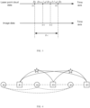
- FIG. 3 shows an example of the linear interpolation.
- FIG. 3 schematically shows a schematic diagram of a principle of an interpolation calculation according to embodiments of the present disclosure.
- adjacent radar data acquisition time instants t l 1 and t l 2 may be obtained according to the acquisition time t c of the visual image data
- the point cloud data may be projected to the image plane for a first time based on depth information D 1 and D 2 of the point cloud data at the time instants t l 1 and t l 2 , so as to obtain a range of rows t l-c where the projected laser points are located.
- the second projection is performed by means of linear interpolation.
- the point cloud data may be projected to a visual image plane corresponding to acquisition time instants t c 1 and t c 2 based on the depth information D 1 + ⁇ d and D 1 +2 ⁇ d and the range of rows t l-c .
- the depth information at the acquisition time instants t c 1 and t c 2 may be obtained by interpolation.
- a depth of a visual feature point may be calculated by using a point cloud data patch around the visual feature point.
- An example method is similar to LIMO and will not be described in detail here.
- the depth value may also be calculated using a triangulation of multiple frames of visual image, which is not limited in the present disclosure. Since a vertical viewing angle of a LiDAR is generally smaller than a viewing angle of a visual image acquisition device of a camera, or a valid observation distance of the LiDAR is limited, some visual image areas may not be covered by the laser point cloud data. Therefore, the depth information of some visual feature points may not be calculated from the laser point cloud data.
- the depth of feature points may be calculated by triangulation of multiple frames of image observation data, that is, only a feature point that is stably tracked for more than a certain number of frames is triangulated. Compared with a two-frame triangulation, this method may be implemented to estimate the depth of the feature points more accurately, so that a negative impact of an error in an estimation of feature point depth on an accuracy of a motion estimation may be reduced.
- a graph optimization method based on a sliding window may be adopted.
- X x 0 , x 1 , ... , x n ⁇ 1
- X represents the positioning data, based on which the autonomous vehicle may be positioned.
- the positioning data may be used in fields of environment perception, motion control, relative positioning, map construction, etc.
- FIG. 4 schematically shows a schematic diagram of a factor graph according to embodiments of the present disclosure.
- a hollow circle represents a LiDAR node
- a hollow square represents a visual node
- a hollow pentagram represents a visual feature
- a dot dash line represents an IMU pre-integration factor
- a dashed line represents an ICP factor
- a line segment represents a visual factor.
- the sensor data may be processed based on the first constraint factor, the second constraint factor and the third constraint factor to obtain the positioning data for positioning the autonomous vehicle.
- X may be determined as the positioning data according to the following equations.
- the IMU pre-integration factor r imu represents a constraint relationship created for states between adjacent key frames according to an IMU pre-integration result.
- a unified serial IMU pre-integration factor is created for a visual image key frames and laser point cloud key frames.
- the IMU measurement value may be effectively used to constrain the states of all dimensions of the node, so as to help effectively estimate a velocity of the node.
- the visual factor r vision represents a constraint relationship created for visual key frames.
- the re-projection error is used as the visual factor.
- an influence of the Rolling Shutter on the plane projection coordinate is eliminated when calculating the re-projection error.
- ⁇ T i and ⁇ T j represent relative motions of the IMU coordinate system during a generation of the two frames of visual data, which may be set as constants in the optimization process using a predicted motion prior value.
- T ′ b i w and T ′ b j w represent states of the IMU coordinate system at corresponding time instants, which are obtained by performing a linear interpolation of motion according to row coordinates of the feature point on the corresponding imaging plan. This is a correction to an imaging time state of the Rolling Shutter image sensor.
- ⁇ c represents a camera projection model.
- ⁇ c ⁇ 1 represents an inverse process of the camera projection model.
- ⁇ l represents an inverse depth value of the visual feature l observed in the i th frame.
- the visual image data may be fused with the point cloud data according to Equation (4), so as to obtain a fused image, and the inverse depth value ⁇ l may be calculated according to the point cloud data patch around the feature point of the image data in the fused image, which is not limited in the present disclosure.
- the ICP factor r icp represents a state constraint created for a LiDAR key frame.
- r icp z ⁇ s e X Log T s w ⁇ 1 T e w ⁇ 1 T ⁇ e s
- T ⁇ e s represents a relative pose between laser point cloud frames output by a LiDAR front end, which may be, for example, the above-mentioned T obtained based on the ICP method
- Log represents a logarithmic mapping of a three-dimensional rigid body transformation, resulting a six-dimensional vector.
- the inertial measurement data is acquired by an inertial sensor, and a velocity and an acceleration of the inertial sensor may be initialized according to the LiDAR data and the first constraint factor.
- the inertial sensor needs to be initialized.
- a purpose of initialization is to estimate a state of a key frame node, including a global pose, a velocity, an accelerometer bias, a gyroscope bias, etc. by constructing an initial key frame sequence, and estimate a direction of gravity so as to establish an accurate initial state of the system.
- the initialization is a premise of a normal operation of the system. For a system with a visual image sensor, it is further needed to build a scale information of a visual map in the initialization process. If the initialization accuracy is not high or even no initialization is performed, the system state is difficult to converge, thus reducing the system accuracy.
- the inertial sensor may be initialized using the LiDAR data.
- the inertial sensor may also be initialized using the visual image data and the wheel speedometer data.
- the relative motion between frames may be calculated through the LiDAR front end in a non-degeneration scene.
- a subsequent initialization process may include a gyroscope bias estimation stage and a velocity and gravitational acceleration estimation stage.
- the initialization may be implemented using VINS-Mono (Versatile Monocular Visual Inertial State Estimator, an open-source monocular inertial visual odometry VIO developed by Hong Kong University of Science and Technology).
- VINS-Mono Very Monocular Visual Inertial State Estimator, an open-source monocular inertial visual odometry VIO developed by Hong Kong University of Science and Technology.
- the gyroscope bias of the IMU may be calculated according to an estimation of a rotational motion between key frames and a pre-integration result of the IMU on the rotational motion.
- the pre-integration needs to be performed again to ensure an accuracy of the pre-integration result.
- details will not be described in embodiments of the present disclosure.
- the following initialization problem may be constructed by combining a motion estimation result and a velocity and displacement result in the IMU pre-integration: min X I ⁇ k ⁇ F ⁇ r imu I z ⁇ b k + 1 b k X I ⁇ 2 + ⁇ ⁇ g w ⁇ 2 ⁇ 9.8 2 ⁇ 2 where represents a set of key frames in the sliding window.
- p b k w and R b k w are known quantities, which are calculated from the LiDAR data and need not to be optimized.
- Another optimization objective function is based on a fact that a magnitude of gravitational acceleration on the Earth's surface is approximated as a constant 9.8m/s 2 , so as to ensure that the gravitational acceleration may be calculated more accurately.
- the velocity component may be directly observed, but only the velocity component, the IMU gyroscope bias and the gravitational acceleration vector are optimized.
- An initial value of the IMU accelerometer bias may be set to zero. The above method may be used in a wide range, and it is also applicable to a method of obtaining a relative motion between frames through other sensors.
- the IMU may be initialized by using an inter-frame constraint obtained from the visual image data, and it is only required to calculate p b k w and R b k w in Equation (16) from the visual image data.
- the initialization may be performed using the visual image data and the wheel speedometer data without LiDAR data. Since the gyroscope bias is assumed to be zero when the inter-frame motion is calculated using the IMU and the wheel speedometer, an estimation of the gyroscope bias is omitted in such initialization method, and the gyroscope bias is directly assumed to be zero.
- the initialization with an assistance of wheel speedometer data has advantages that it is simple be to implemented, has a low requirement on the initial motion condition, and generally has a sufficient accuracy, thus avoiding an excessive size caused by a requirement of a simple IMU and visual initialization on a vehicle mobility.
- the visual key frame node and the LiDAR key frame node are optimized by using the same factor graph, and the visual key frame nodes and the LiDAR key frame nodes are previously connected in sequence in a chronological order through the IMU pre-integration factor, so the IMU pre-integration operation is required to be serial processing.
- the update of the sliding window and the operation of fusion and optimization require a thread synchronization, that is, parallel processing.
- the parallel processing may be performed using the GPU, so that the usage of CPU resources may be reduced, and the GPU resources may be reasonably used.
- separate threads may be created to process the visual image data and the LiDAR data respectively, so as to enable the parallel processing.
- serial processing such as the IMU pre-integration, a correctness of timing may be ensured by the thread synchronization.
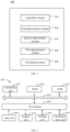
- FIG. 5 schematically shows a block diagram of an apparatus for processing data for an autonomous vehicle according to embodiments of the present disclosure.
- an apparatus for processing data 500 for an autonomous vehicle in embodiments of the present disclosure may include, for example, an acquisition module 510, a first determination module 520, a second determination module 530, a third determination module 540, and a processing module 550.
- the acquisition module 510 may be used to acquire sensor data for the autonomous vehicle, and the sensor data includes inertial measurement data, LiDAR data, and visual image data. According to embodiments of the present disclosure, the acquisition module 510 may perform, for example, the operation S110 described above with reference to FIG. 1 , which will not be repeated here.
- the first determination module 520 may be used to determine a first constraint factor for the inertial measurement data according to the inertial measurement data and the visual image data. According to embodiments of the present disclosure, the first determination module 520 may perform, for example, the operation S120 described above with reference to FIG. 1 , which will not be repeated here.
- the second determination module 530 may be used to determine a second constraint factor for the LiDAR data according to the inertial measurement data and the LiDAR data. According to embodiments of the present disclosure, the second determination module 530 may perform, for example, the operation S 130 described above with reference to FIG. 1 , which will not be repeated here.
- the third determination module 540 may be used to determine a third constraint factor for the visual image data according to the inertial measurement data, the visual image data and the LiDAR data. According to embodiments of the present disclosure, the third determination module 540 may perform, for example, the operation S 140 described above with reference to FIG. 1 , which will not be repeated here.
- the processing module 550 may be used to process the sensor data based on the first constraint factor, the second constraint factor and the third constraint factor, so as to obtain positioning data for positioning the autonomous vehicle. According to embodiments of the present disclosure, the processing module 550 may perform, for example, the operation S 150 described above with reference to FIG. 1 , which will not be repeated here.
- the LiDAR data includes a plurality of frames of laser point cloud data
- the second determination module 530 includes a first determination sub-module, a second determination sub-module, an adjustment sub-module, and a third determination sub-module.
- the first determination sub-module is used to determine an initial relative pose between a first frame of laser point cloud data and a second frame of laser point cloud data among the plurality of frames of laser point cloud data according to the inertial measurement data, the first frame of laser point cloud data and the second frame of laser point cloud data.
- the second determination sub-module is used to determine first projection data of the first frame of laser point cloud data and second projection data of the second frame of laser point cloud data, respectively.
- the adjustment sub-module is used to adjust the initial relative pose according to the first projection data and the second projection data, so as to obtain a relative pose between point cloud frames.
- the third determination sub-module is used to determine the second constraint factor according to the relative pose between point cloud frames.
- the first projection data includes N voxels
- the second projection data includes N voxels
- N is an integer greater than 1
- the adjustment sub-module is further used to: perform N iterations according to each of the N voxels and the initial relative pose, so as to obtain an Nth relative pose as the relative pose between point cloud frames.
- an acquisition, a storage, a use, a processing, a transmission, a provision and a disclosure of user personal information and location information involved comply with provisions of relevant laws and regulations, and do not violate public order and good custom.
- the present disclosure further provides an electronic device, a readable storage medium, and a computer program product.
- FIG. 6 shows a block diagram of an electronic device for implementing the method of processing data for the autonomous vehicle according to embodiments of the present disclosure.
- FIG. 6 shows a schematic block diagram of an exemplary electronic device 600 for implementing embodiments of the present disclosure.
- the electronic device 600 is intended to represent various forms of digital computers, such as a laptop computer, a desktop computer, a workstation, a personal digital assistant, a server, a blade server, a mainframe computer, and other suitable computers.
- the electronic device may further represent various forms of mobile devices, such as a personal digital assistant, a cellular phone, a smart phone, a wearable device, and other similar computing devices.
- the components as illustrated herein, and connections, relationships, and functions thereof are merely examples, and are not intended to limit the implementation of the present disclosure described and/or required herein.
- the electronic device 600 includes a computing unit 601 which may perform various appropriate actions and processes according to a computer program stored in a read only memory (ROM) 602 or a computer program loaded from a storage unit 608 into a random access memory (RAM) 603.
- ROM read only memory
- RAM random access memory
- various programs and data necessary for an operation of the electronic device 600 may also be stored.
- the computing unit 601, the ROM 602 and the RAM 603 are connected to each other through a bus 604.
- An input/output (I/O) interface 605 is also connected to the bus 604.
- a plurality of components in the electronic device 600 are connected to the I/O interface 605, including: an input unit 606, such as a keyboard, or a mouse; an output unit 607, such as displays or speakers of various types; a storage unit 608, such as a disk, or an optical disc; and a communication unit 609, such as a network card, a modem, or a wireless communication transceiver.
- the communication unit 609 allows the electronic device 600 to exchange information/data with other devices through a computer network such as Internet and/or various telecommunication networks.
- the computing unit 601 may be various general-purpose and/or dedicated processing assemblies having processing and computing capabilities. Some examples of the computing units 601 include, but are not limited to, a central processing unit (CPU), a graphics processing unit (GPU), various dedicated artificial intelligence (AI) computing chips, various computing units that run machine learning model algorithms, a digital signal processing processor (DSP), and any suitable processor, controller, microcontroller, etc.
- the computing unit 601 executes various methods and steps described above, such as the method of processing data for the autonomous vehicle.
- the method of processing data for the autonomous vehicle may be implemented as a computer software program which is tangibly embodied in a machine-readable medium, such as the storage unit 608.
- the computer program may be partially or entirely loaded and/or installed in the electronic device 600 via the ROM 602 and/or the communication unit 609.
- the computer program when loaded in the RAM 603 and executed by the computing unit 601, may execute one or more steps in the method of processing data for the autonomous vehicle described above.
- the computing unit 601 may be configured to perform the method of processing data for the autonomous vehicle by any other suitable means (e.g., by means of firmware).
- Various embodiments of the systems and technologies described herein may be implemented in a digital electronic circuit system, an integrated circuit system, a field programmable gate array (FPGA), an application specific integrated circuit (ASIC), an application specific standard product (ASSP), a system on chip (SOC), a complex programmable logic device (CPLD), a computer hardware, firmware, software, and/or combinations thereof.
- FPGA field programmable gate array
- ASIC application specific integrated circuit
- ASSP application specific standard product
- SOC system on chip
- CPLD complex programmable logic device
- the programmable processor may be a dedicated or general-purpose programmable processor, which may receive data and instructions from a storage system, at least one input device and at least one output device, and may transmit the data and instructions to the storage system, the at least one input device, and the at least one output device.
- Program codes for implementing the methods of the present disclosure may be written in one programming language or any combination of more programming languages. These program codes may be provided to a processor or controller of a general-purpose computer, a dedicated computer or other programmable data processing apparatus, such that the program codes, when executed by the processor or controller, cause the functions/operations specified in the flowcharts and/or block diagrams to be implemented.
- the program codes may be executed entirely on a machine, partially on a machine, partially on a machine and partially on a remote machine as a stand-alone software package or entirely on a remote machine or server.
- a machine-readable medium may be a tangible medium that may contain or store a program for use by or in connection with an instruction execution system, an apparatus or a device.
- the machine-readable medium may be a machine-readable signal medium or a machine-readable storage medium.
- the machine-readable medium may include, but is not limited to, an electronic, magnetic, optical, electromagnetic, infrared, or semiconductor system, apparatus or device, or any suitable combination of the above.
- machine-readable storage medium may include an electrical connection based on one or more wires, a portable computer disk, a hard disk, a random access memory (RAM), a read only memory (ROM), an erasable programmable read only memory (EPROM or a flash memory), an optical fiber, a compact disk read only memory (CD-ROM), an optical storage device, a magnetic storage device, or any suitable combination of the above.
- RAM random access memory
- ROM read only memory
- EPROM or a flash memory erasable programmable read only memory
- CD-ROM compact disk read only memory
- magnetic storage device or any suitable combination of the above.
- a computer including a display device (for example, a CRT (cathode ray tube) or LCD (liquid crystal display) monitor) for displaying information to the user, and a keyboard and a pointing device (for example, a mouse or a trackball) through which the user may provide the input to the computer.
- a display device for example, a CRT (cathode ray tube) or LCD (liquid crystal display) monitor
- a keyboard and a pointing device for example, a mouse or a trackball
- Other types of devices may also be used to provide interaction with the user.
- a feedback provided to the user may be any form of sensory feedback (for example, visual feedback, auditory feedback, or tactile feedback), and the input from the user may be received in any form (including acoustic input, voice input or tactile input).
- the systems and technologies described herein may be implemented in a computing system including back-end components (for example, a data server), or a computing system including middleware components (for example, an application server), or a computing system including front-end components (for example, a user computer having a graphical user interface or web browser through which the user may interact with the implementation of the system and technology described herein), or a computing system including any combination of such back-end components, middleware components or front-end components.
- the components of the system may be connected to each other by digital data communication (for example, a communication network) in any form or through any medium. Examples of the communication network include a local area network (LAN), a wide area network (WAN), and the Internet.
- LAN local area network
- WAN wide area network
- the Internet the global information network
- the computer system may include a client and a server.
- the client and the server are generally far away from each other and usually interact through a communication network.
- the relationship between the client and the server is generated through computer programs running on the corresponding computers and having a client-server relationship with each other.
- the server may be a cloud server, a server of a distributed system, or a server combined with a block-chain.
Landscapes
- Engineering & Computer Science (AREA)
- Physics & Mathematics (AREA)
- Radar, Positioning & Navigation (AREA)
- Remote Sensing (AREA)
- General Physics & Mathematics (AREA)
- Mechanical Engineering (AREA)
- Transportation (AREA)
- Automation & Control Theory (AREA)
- Computer Networks & Wireless Communication (AREA)
- Electromagnetism (AREA)
- Combustion & Propulsion (AREA)
- Chemical & Material Sciences (AREA)
- Computer Vision & Pattern Recognition (AREA)
- Human Computer Interaction (AREA)
- Theoretical Computer Science (AREA)
- Mathematical Physics (AREA)
- Multimedia (AREA)
- Optical Radar Systems And Details Thereof (AREA)
- Traffic Control Systems (AREA)
- Control Of Driving Devices And Active Controlling Of Vehicle (AREA)
- Control Of Position, Course, Altitude, Or Attitude Of Moving Bodies (AREA)
- Image Analysis (AREA)
- Image Processing (AREA)
Claims (9)
- Ein Verfahren zum Verarbeiten von Daten für ein autonomes Fahrzeug, das folgende Schritte aufweist:Erfassen (S110) von Sensordaten für das autonome Fahrzeug, wobei die Sensordaten Trägheitsmess-Daten, LiDAR-Daten und visuelle Bilddaten aufweisen;Bestimmen (S120) eines ersten Beschränkungsfaktors für die Trägheitsmess-Daten gemäß den Trägheitsmess-Daten und den visuellen Bilddaten;Bestimmen (S130) eines zweiten Beschränkungsfaktors für die LiDAR-Daten gemäß den Trägheitsmess-Daten und die LiDAR-Daten;Bestimmen (S140) eines dritten Beschränkungsfaktors für die visuellen Bilddaten gemäß den Trägheitsmess-Daten, den visuellen Bilddaten und den LiDAR-Daten; undVerarbeiten (S150) der Sensordaten basierend auf dem ersten Beschränkungsfaktor, dem zweiten Beschränkungsfaktor und dem dritten Beschränkungsfaktor, um so Positionierungsdaten zum Positionieren des autonomen Fahrzeugs zu erhalten,wobei das Bestimmen (S140) eines dritten Beschränkungsfaktors für die visuellen Bilddaten gemäß den Trägheitsmess-Daten, den visuellen Bilddaten und den LiDAR-Daten folgende Schritte aufweist:Bestimmen einer Tiefeninformation der visuellen Bilddaten gemäß den visuellen Bilddaten und den LiDAR-Daten;Bestimmen einer Abbildungsbeziehung zwischen den visuellen Bilddaten und den Trägheitsmess-Daten gemäß den visuellen Bilddaten und den Trägheitsmess-Daten; undBestimmen des dritten Beschränkungsfaktors gemäß den Tiefeninformationen und der Abbildungsbeziehung.
- Das Verfahren gemäß Anspruch 1, bei dem die LiDAR-Daten eine Mehrzahl von Rahmen von Laserpunkt-Cloud-Daten aufweisen; und das Bestimmen eines zweiten Beschränkungsfaktors für die LiDAR-Daten gemäß den Trägheitsmess-Daten und den LiDAR-Daten folgende Schritte aufweist:Bestimmen einer relativen Anfangspose zwischen einem ersten Rahmen von Laserpunkt-Cloud-Daten und einem zweiten Rahmen von Laserpunkt-Cloud-Daten unter der Mehrzahl von Rahmen von Laserpunkt-Cloud-Daten gemäß den Trägheitsmess-Daten, dem ersten Rahmen von Laserpunkt-Cloud-Daten und dem zweiten Rahmen von Laserpunkt-Cloud-Daten;Bestimmen erster Projektionsdaten des ersten Rahmens von Laserpunkt-Cloud-Daten und zweiten Projektionsdaten des zweiten Rahmens von Laserpunkt-Cloud-Daten;Anpassen der relativen Anfangspose gemäß den ersten Projektionsdaten und den zweiten Projektionsdaten, um so eine relative Pose zwischen Punkt-Cloud-Rahmen zu erhalten; undBestimmen des zweiten Beschränkungsfaktors gemäß der relativen Pose zwischen Punkt-Cloud-Rahmen.
- Das Verfahren gemäß Anspruch 2, bei dem die ersten Projektionsdaten N Voxel aufweisen, die zweiten Projektionsdaten N Voxel aufweisen und N eine Ganzzahl größer als 1 ist; das Anpassen der relativen Anfangspose gemäß den ersten Projektionsdaten und den zweiten Projektionsdaten, um so eine relative Pose zwischen Punkt-Cloud-Rahmen zu erhalten, Folgendes aufweist:Durchführen von N Iterationen gemäß der relativen Anfangspose und jedem der N Voxel, um so eine N-te relative Pose als die relative Pose zwischen Punkt-Cloud-Rahmen zu erhalten,wobei die ersten Projektionsdaten ein erstes Projektionsbild und einen ersten Normalvektor aufweisen und die zweiten Projektionsdaten ein zweites Projektionsbild und einen zweiten Normalvektor aufweisen; das Anpassen der relativen Anfangspose gemäß den ersten Projektionsdaten und den zweiten Projektionsdaten, um so eine relative Pose zwischen Punkt-Cloud-Rahmen zu erhalten, Folgendes aufweist:
bei einer i-ten Iteration bei den N Iterationen:Bestimmen einer Entfernungsschwelle und einer Winkelschwelle gemäß i, wobei i größer oder gleich 1 und kleiner oder gleich N ist;Bestimmen, ansprechend auf eine Bestimmung, dass eine Entfernung zwischen einem i-ten ersten Pixel in dem ersten Projektionsbild und einem i-ten zweiten Pixel in dem zweiten Projektionsbild kleiner oder gleich der Entfernungsschwelle ist, und dass ein Winkel zwischen dem ersten Normalvektor, der einem i-ten Pixel entspricht, und dem zweiten Normalvektor, der dem i-ten Pixel entspricht, kleiner oder gleich der Winkelschwelle ist, einer i-ten relativen Pose durch Verwenden einer (i-1)-ten relativen Pose, die erhalten wird aus einer (i-1)-ten Iteration, dem i-ten ersten Pixel, dem i-ten zweiten Pixel, dem ersten Normalvektor, der dem i-ten Pixel entspricht, und dem zweiten Normalvektor, der dem i-ten Pixel entspricht. - Das Verfahren gemäß Anspruch 1, bei dem das Bestimmen einer Tiefeninformation der visuellen Bilddaten gemäß den visuellen Bilddaten und den LiDAR-Daten folgende Schritte aufweist:Bestimmen einer relativen Anfangs-Trägheitsmess-Pose zu einem visuellen Bilderfassungszeitpunkt der visuellen Bilddaten relativ zu einem Radardatenerfassungszeitpunkt benachbarter Radardaten;Bestimmen einer ersten Projektionsposition der LiDAR-Daten zu einer visuellen Bilddatenebene gemäß dem visuellen Bilderfassungszeitpunkt, dem Radardatenerfassungszeitpunkt und der relativen Anfangs-Trägheitsmess-Pose;Bestimmen eines Bildprojektionszeitpunkts und einer aktualisierten relativen Trägheitsmess-Pose gemäß der ersten Projektionsposition; undBestimmen der Tiefeninformation der visuellen Bilddaten gemäß der aktualisierten relativen Trägheitsmess-Pose.
- Das Verfahren gemäß Anspruch 4, bei dem das Bestimmen eines Bildprojektionszeitpunkts und einer aktualisierten relativen Trägheitsmess-Pose gemäß der ersten Projektionsposition folgende Schritte aufweist:Bestimmen einer ersten relativen Trägheitsmess-Pose zu dem visuellen Bilderfassungszeitpunkt relativ zu dem Bildprojektionszeitpunkt;Bestimmen einer zweiten relativen Trägheitsmess-Pose zu dem Bildprojektionszeitpunkt relativ zu dem Laserdatenerfassungszeitpunkt; undDurchführen einer Interpolation an der relativen Anfangs-Trägheitsmess-Pose durch Verwenden der ersten relativen Trägheitsmess-Pose und der zweiten relativen Trägheitsmess-Pose, um so die aktualisierte relative Trägheitsmess-Pose zu erhalten.
- Das Verfahren gemäß einem der Ansprüche 1 bis 5, bei dem die Trägheitsmess-Daten durch einen Trägheitssensor erfasst werden und das Verfahren ferner folgenden Schritt aufweist:
Initialisieren einer Geschwindigkeit des Trägheitssensors und einer Beschleunigung des Trägheitssensors gemäß den LiDAR-Daten und dem ersten Beschränkungsfaktor. - Eine elektronische Vorrichtung (600), die folgende Merkmale aufweist:zumindest einen Prozessor (601), undeinen Speicher (608), der kommunikativ mit dem zumindest einen Prozessor (601) verbunden ist, wobei der Speicher (608) Befehle speichert, die durch den zumindest einen Prozessor (601) ausführbar sind, und die Befehle, wenn sie durch den zumindest einen Prozessor (601) ausgeführt werden, bewirken, dass der zumindest eine Prozessor (601) das Verfahren gemäß einem der Ansprüche 1 bis 6 implementiert.
- Ein nichtflüchtiges computerlesbares Speichermedium mit Computerbefehlen, wobei die Computerbefehle dazu ausgebildet sind, zu bewirken, dass ein Computer das Verfahren gemäß einem der Ansprüche 1 bis 6 implementiert.
- Ein Computerprogrammprodukt mit einen Computerprogramm, wobei das Computerprogramm bei Ausführung durch einen Prozessor bewirkt, dass der Prozessor das Verfahren gemäß einem der Ansprüche 1 bis 6 implementiert.
Applications Claiming Priority (1)
| Application Number | Priority Date | Filing Date | Title |
|---|---|---|---|
| CN202111291238.0A CN114013449B (zh) | 2021-11-02 | 2021-11-02 | 针对自动驾驶车辆的数据处理方法、装置和自动驾驶车辆 |
Publications (2)
| Publication Number | Publication Date |
|---|---|
| EP4160271A1 EP4160271A1 (de) | 2023-04-05 |
| EP4160271B1 true EP4160271B1 (de) | 2024-05-01 |
Family
ID=80059937
Family Applications (1)
| Application Number | Title | Priority Date | Filing Date |
|---|---|---|---|
| EP22204106.3A Active EP4160271B1 (de) | 2021-11-02 | 2022-10-27 | Verfahren und vorrichtung zur verarbeitung von daten für ein autonomes fahrzeug, elektronische vorrichtung und speichermedium |
Country Status (5)
| Country | Link |
|---|---|
| US (1) | US12214800B2 (de) |
| EP (1) | EP4160271B1 (de) |
| JP (1) | JP7369847B2 (de) |
| KR (1) | KR20220153535A (de) |
| CN (1) | CN114013449B (de) |
Families Citing this family (27)
| Publication number | Priority date | Publication date | Assignee | Title |
|---|---|---|---|---|
| CN114706805B (zh) * | 2022-03-31 | 2024-03-15 | 重庆长安汽车股份有限公司 | 一种根据目标序号对传感融合信息进行排序的方法、电子设备及计算机可读存储介质 |
| CN114429432B (zh) * | 2022-04-07 | 2022-06-21 | 科大天工智能装备技术(天津)有限公司 | 一种多源信息分层融合方法、装置及存储介质 |
| CN115112116B (zh) * | 2022-06-29 | 2025-10-21 | 北京易航远智科技有限公司 | 基于多传感器的紧耦合里程计方法、装置、设备及存储介质 |
| CN115113627B (zh) * | 2022-07-27 | 2024-11-19 | 深圳市普渡科技有限公司 | 机器人、路径规划方法和计算机可读存储介质 |
| CN115423839B (zh) * | 2022-08-23 | 2026-03-03 | 浙江乌镇街科技有限公司 | 三维点云数据的运动补偿方法、装置、介质及电子设备 |
| CN117029802A (zh) * | 2022-11-05 | 2023-11-10 | 合肥图灵纪元科技有限公司 | 一种基于深度学习的多模态slam方法 |
| CN116164777A (zh) * | 2022-12-27 | 2023-05-26 | 北京百度网讯科技有限公司 | 传感器标定方法、装置、设备及自动驾驶车辆 |
| CN116989763B (zh) * | 2023-05-10 | 2024-07-19 | 广东工业大学 | 一种面向水陆两用无人系统的融合定位与建图方法 |
| CN119025874A (zh) * | 2023-05-19 | 2024-11-26 | 北京小米机器人技术有限公司 | 姿态识别方法及装置、电子设备、存储介质 |
| CN116634077A (zh) * | 2023-05-25 | 2023-08-22 | 中国电影科学技术研究所 | 一种led虚拟拍摄中摄影机追踪方法和装置 |
| CN117233784A (zh) * | 2023-05-26 | 2023-12-15 | 南方电网调峰调频发电有限公司储能科研院 | 水下机器人隧洞定位方法、系统、计算机设备及存储介质 |
| CN116929377A (zh) * | 2023-06-07 | 2023-10-24 | 合众新能源汽车股份有限公司 | 激光雷达与惯导融合定位方法及相关设备 |
| CN116777967B (zh) * | 2023-06-21 | 2025-10-31 | 北京百度网讯科技有限公司 | 一种数据处理方法、装置、设备及存储介质 |
| CN116817916A (zh) * | 2023-06-26 | 2023-09-29 | 中国电信股份有限公司 | 位姿信息确定方法、装置、电子设备及非易失性存储介质 |
| TWI864914B (zh) * | 2023-07-28 | 2024-12-01 | 新馳科技股份有限公司 | 外部參數校正系統及其外部參數校正之方法 |
| CN117237902B (zh) * | 2023-11-15 | 2024-01-26 | 山东飞宏工程机械有限公司 | 基于深度学习的机器人物体识别系统 |
| CN117572453B (zh) * | 2023-11-16 | 2024-12-13 | 北京易航远智科技有限公司 | 雷达里程计建图方法、装置、电子设备及存储介质 |
| CN120103404A (zh) * | 2023-12-04 | 2025-06-06 | 浙江吉利控股集团有限公司 | 一种位姿确定方法、装置及电子设备 |
| CN118466572B (zh) * | 2024-04-30 | 2025-02-28 | 武汉大学 | Gnss拒止环境梁底ndt任务驱动的uav自主循迹飞行控制方法 |
| CN118155039B (zh) * | 2024-05-13 | 2024-07-26 | 齐鲁空天信息研究院 | 多源信息融合的定位地图构建方法、装置、介质及设备 |
| CN121632102A (zh) * | 2024-08-29 | 2026-03-10 | 上海司南导航技术股份有限公司 | 测量方法、系统、设备及计算机可读存储介质 |
| CN118816935B (zh) * | 2024-09-18 | 2025-01-21 | 青岛慧拓智能机器有限公司 | 一种基于面元拟合的多传感器融合里程计生成方法及系统 |
| CN119354208B (zh) * | 2024-10-18 | 2025-04-18 | 东南大学 | 一种基于LiDAR/IMU/UWB紧耦合里程计的车辆定位方法 |
| CN119178433B (zh) * | 2024-11-21 | 2025-04-01 | 北京清瞳时代科技有限公司 | 一种定位方法、装置、计算设备和程序产品 |
| CN119354180B (zh) * | 2024-12-25 | 2025-03-18 | 山东科技大学 | 基于异构多模态数据融合的同步定位与建图方法 |
| CN120950130B (zh) * | 2025-07-31 | 2026-04-28 | 青岛小鸟看看科技有限公司 | 终端初始化方法、装置、电子设备和存储介质 |
| CN120703725B (zh) * | 2025-08-26 | 2025-10-28 | 南京天创智能科技股份有限公司 | 一种稳健抗干扰的3d点云定位方法及系统 |
Family Cites Families (23)
| Publication number | Priority date | Publication date | Assignee | Title |
|---|---|---|---|---|
| US9835717B2 (en) * | 2012-04-17 | 2017-12-05 | Commonwealth Scientific And Industrial Research Organisation | Three dimensional scanning beam and imaging system |
| BR112021004229A2 (pt) * | 2018-09-07 | 2021-05-25 | Huawei Technologies Co., Ltd. | dispositivo e método para realizar localização e mapeamento simultâneos |
| CN109341706B (zh) * | 2018-10-17 | 2020-07-03 | 张亮 | 一种面向无人驾驶汽车的多特征融合地图的制作方法 |
| US11555903B1 (en) * | 2018-11-30 | 2023-01-17 | Zoox, Inc. | Sensor calibration using dense depth maps |
| CN110009739B (zh) * | 2019-01-29 | 2023-03-24 | 浙江省北大信息技术高等研究院 | 移动摄像机的数字视网膜的运动特征的提取与编码方法 |
| US11352010B2 (en) * | 2019-09-30 | 2022-06-07 | Baidu Usa Llc | Obstacle perception calibration system for autonomous driving vehicles |
| CN110986968B (zh) * | 2019-10-12 | 2022-05-24 | 清华大学 | 三维重建中实时全局优化和错误回环判断的方法及装置 |
| WO2021105218A1 (en) * | 2019-11-27 | 2021-06-03 | Continental Automotive Gmbh | Method for generating 3d reference points in a map of a scene |
| CN110906923B (zh) * | 2019-11-28 | 2023-03-14 | 重庆长安汽车股份有限公司 | 车载多传感器紧耦合融合定位方法、系统、存储介质及车辆 |
| JP7692152B2 (ja) * | 2020-02-14 | 2025-06-13 | パナソニックIpマネジメント株式会社 | 情報処理方法、情報処理システム及び情報処理装置 |
| JP7196876B2 (ja) * | 2020-03-30 | 2022-12-27 | 株式会社豊田中央研究所 | センサ遅延時間推定装置 |
| CN111595333B (zh) * | 2020-04-26 | 2023-07-28 | 武汉理工大学 | 视觉惯性激光数据融合的模块化无人车定位方法及系统 |
| AU2021204030A1 (en) * | 2020-06-28 | 2022-01-20 | Beijing Tusen Weilai Technology Co., Ltd. | Multi-sensor calibration system |
| CN112304307B (zh) * | 2020-09-15 | 2024-09-06 | 浙江大华技术股份有限公司 | 一种基于多传感器融合的定位方法、装置和存储介质 |
| US11543263B1 (en) * | 2020-09-16 | 2023-01-03 | Zoox, Inc. | Map distortion determination |
| US11734880B2 (en) * | 2020-12-31 | 2023-08-22 | Waymo Llc | Sensor calibration with environment map |
| US11940793B1 (en) * | 2021-02-26 | 2024-03-26 | Zoox, Inc. | Vehicle component validation using adverse event simulation |
| CN112598757B (zh) * | 2021-03-03 | 2021-06-01 | 之江实验室 | 一种多传感器时间空间标定方法及装置 |
| CN112985394B (zh) * | 2021-05-12 | 2021-08-06 | 腾讯科技(深圳)有限公司 | 定位方法和装置、存储介质 |
| KR102499334B1 (ko) * | 2021-06-28 | 2023-02-14 | (주)뷰런테크놀로지 | 라이다 센서를 이용하여 차선을 검출하는 방법 및 상기 방법을 수행하는 차선 검출 장치 |
| US11680824B1 (en) * | 2021-08-30 | 2023-06-20 | Zoox, Inc. | Inertial measurement unit fault detection |
| KR102367138B1 (ko) * | 2021-10-13 | 2022-02-25 | (주)뷰런테크놀로지 | 라이다 센서를 이용하여 횡단보도를 검출하는 방법 및 상기 방법을 수행하는 횡단보도 검출 장치 |
| US12026956B1 (en) * | 2021-10-28 | 2024-07-02 | Zoox, Inc. | Object bounding contours based on image data |
-
2021
- 2021-11-02 CN CN202111291238.0A patent/CN114013449B/zh active Active
-
2022
- 2022-10-27 EP EP22204106.3A patent/EP4160271B1/de active Active
- 2022-10-28 US US17/975,689 patent/US12214800B2/en active Active
- 2022-10-31 KR KR1020220142931A patent/KR20220153535A/ko not_active Withdrawn
- 2022-10-31 JP JP2022173997A patent/JP7369847B2/ja active Active
Also Published As
| Publication number | Publication date |
|---|---|
| EP4160271A1 (de) | 2023-04-05 |
| CN114013449A (zh) | 2022-02-08 |
| US12214800B2 (en) | 2025-02-04 |
| US20230118945A1 (en) | 2023-04-20 |
| JP2023021994A (ja) | 2023-02-14 |
| CN114013449B (zh) | 2023-11-03 |
| JP7369847B2 (ja) | 2023-10-26 |
| KR20220153535A (ko) | 2022-11-18 |
Similar Documents
| Publication | Publication Date | Title |
|---|---|---|
| EP4160271B1 (de) | Verfahren und vorrichtung zur verarbeitung von daten für ein autonomes fahrzeug, elektronische vorrichtung und speichermedium | |
| US11361196B2 (en) | Object height estimation from monocular images | |
| EP4155679B1 (de) | Positionierungsverfahren und -vorrichtung auf basis von fahrspurlinie und merkmalspunkt | |
| US9709404B2 (en) | Iterative Kalman Smoother for robust 3D localization for vision-aided inertial navigation | |
| US9251590B2 (en) | Camera pose estimation for 3D reconstruction | |
| US11514607B2 (en) | 3-dimensional reconstruction method, 3-dimensional reconstruction device, and storage medium | |
| EP3919930B1 (de) | Verfahren und vorrichtung zur bestimmung der geschwindigkeit eines hindernisses, vorrichtung, medium und computerprogrammprodukt | |
| US20220051031A1 (en) | Moving object tracking method and apparatus | |
| US20190301871A1 (en) | Direct Sparse Visual-Inertial Odometry Using Dynamic Marginalization | |
| CN114612544B (zh) | 图像处理方法、装置、设备和存储介质 | |
| CN113639782A (zh) | 车载传感器的外参标定方法和装置、设备和介质 | |
| US12475599B2 (en) | Method and apparatus for calibrating extrinsic parameters of surround-view cameras on a vehicle, vehicle and storage media | |
| CN119379929A (zh) | 三维重建数据的采集方法、电子设备和存储介质 | |
| WO2024230476A1 (zh) | 视觉惯性融合定位方法及设备 | |
| Kottas et al. | An iterative Kalman smoother for robust 3D localization on mobile and wearable devices | |
| CN115307642B (zh) | 车辆位置姿态数据的确定方法、装置及电子设备 | |
| US8351653B2 (en) | Distance estimation from image motion for moving obstacle detection | |
| CN114170300B (zh) | 高精地图点云位姿优化方法、装置、设备及介质 | |
| CN115601573B (zh) | 视觉slam特征匹配方法、系统、装置及可读存储介质 | |
| CN116839572A (zh) | 单目视觉紧耦合方法、装置、计算机可读介质及电子设备 | |
| Li et al. | Monocular Visual–Inertial Odometer Based on Adaptive Variational Bayes Algorithm | |
| US8922648B2 (en) | Rotation cancellation for moving obstacle detection | |
| Solin et al. | A look at improving robustness in visual-inertial SLAM by moment matching | |
| Conway et al. | Vision-based Velocimetry over Unknown Terrain with a Low-Noise IMU | |
| CN113946151A (zh) | 针对自动驾驶车辆的数据处理方法、装置和自动驾驶车辆 |
Legal Events
| Date | Code | Title | Description |
|---|---|---|---|
| PUAI | Public reference made under article 153(3) epc to a published international application that has entered the european phase |
Free format text: ORIGINAL CODE: 0009012 |
|
| STAA | Information on the status of an ep patent application or granted ep patent |
Free format text: STATUS: REQUEST FOR EXAMINATION WAS MADE |
|
| 17P | Request for examination filed |
Effective date: 20221027 |
|
| AK | Designated contracting states |
Kind code of ref document: A1 Designated state(s): AL AT BE BG CH CY CZ DE DK EE ES FI FR GB GR HR HU IE IS IT LI LT LU LV MC ME MK MT NL NO PL PT RO RS SE SI SK SM TR |
|
| GRAP | Despatch of communication of intention to grant a patent |
Free format text: ORIGINAL CODE: EPIDOSNIGR1 |
|
| STAA | Information on the status of an ep patent application or granted ep patent |
Free format text: STATUS: GRANT OF PATENT IS INTENDED |
|
| RIC1 | Information provided on ipc code assigned before grant |
Ipc: G01S 5/16 20060101ALN20231121BHEP Ipc: G01S 17/89 20200101ALI20231121BHEP Ipc: G01C 21/28 20060101ALI20231121BHEP Ipc: G01S 7/48 20060101ALI20231121BHEP Ipc: G01C 21/16 20060101ALI20231121BHEP Ipc: G01S 17/93 20200101ALI20231121BHEP Ipc: G01S 17/86 20200101AFI20231121BHEP |
|
| INTG | Intention to grant announced |
Effective date: 20231207 |
|
| INTG | Intention to grant announced |
Effective date: 20231211 |
|
| GRAS | Grant fee paid |
Free format text: ORIGINAL CODE: EPIDOSNIGR3 |
|
| GRAA | (expected) grant |
Free format text: ORIGINAL CODE: 0009210 |
|
| STAA | Information on the status of an ep patent application or granted ep patent |
Free format text: STATUS: THE PATENT HAS BEEN GRANTED |
|
| P01 | Opt-out of the competence of the unified patent court (upc) registered |
Effective date: 20240308 |
|
| AK | Designated contracting states |
Kind code of ref document: B1 Designated state(s): AL AT BE BG CH CY CZ DE DK EE ES FI FR GB GR HR HU IE IS IT LI LT LU LV MC ME MK MT NL NO PL PT RO RS SE SI SK SM TR |
|
| REG | Reference to a national code |
Ref country code: GB Ref legal event code: FG4D |
|
| REG | Reference to a national code |
Ref country code: CH Ref legal event code: EP |
|
| REG | Reference to a national code |
Ref country code: IE Ref legal event code: FG4D |
|
| REG | Reference to a national code |
Ref country code: DE Ref legal event code: R096 Ref document number: 602022003216 Country of ref document: DE |
|
| REG | Reference to a national code |
Ref country code: LT Ref legal event code: MG9D |
|
| REG | Reference to a national code |
Ref country code: NL Ref legal event code: MP Effective date: 20240501 |
|
| PG25 | Lapsed in a contracting state [announced via postgrant information from national office to epo] |
Ref country code: IS Free format text: LAPSE BECAUSE OF FAILURE TO SUBMIT A TRANSLATION OF THE DESCRIPTION OR TO PAY THE FEE WITHIN THE PRESCRIBED TIME-LIMIT Effective date: 20240901 |
|
| PG25 | Lapsed in a contracting state [announced via postgrant information from national office to epo] |
Ref country code: BG Free format text: LAPSE BECAUSE OF FAILURE TO SUBMIT A TRANSLATION OF THE DESCRIPTION OR TO PAY THE FEE WITHIN THE PRESCRIBED TIME-LIMIT Effective date: 20240501 |
|
| PG25 | Lapsed in a contracting state [announced via postgrant information from national office to epo] |
Ref country code: FI Free format text: LAPSE BECAUSE OF FAILURE TO SUBMIT A TRANSLATION OF THE DESCRIPTION OR TO PAY THE FEE WITHIN THE PRESCRIBED TIME-LIMIT Effective date: 20240501 Ref country code: HR Free format text: LAPSE BECAUSE OF FAILURE TO SUBMIT A TRANSLATION OF THE DESCRIPTION OR TO PAY THE FEE WITHIN THE PRESCRIBED TIME-LIMIT Effective date: 20240501 |
|
| PG25 | Lapsed in a contracting state [announced via postgrant information from national office to epo] |
Ref country code: GR Free format text: LAPSE BECAUSE OF FAILURE TO SUBMIT A TRANSLATION OF THE DESCRIPTION OR TO PAY THE FEE WITHIN THE PRESCRIBED TIME-LIMIT Effective date: 20240802 |
|
| PG25 | Lapsed in a contracting state [announced via postgrant information from national office to epo] |
Ref country code: PT Free format text: LAPSE BECAUSE OF FAILURE TO SUBMIT A TRANSLATION OF THE DESCRIPTION OR TO PAY THE FEE WITHIN THE PRESCRIBED TIME-LIMIT Effective date: 20240902 |
|
| REG | Reference to a national code |
Ref country code: AT Ref legal event code: MK05 Ref document number: 1683111 Country of ref document: AT Kind code of ref document: T Effective date: 20240501 |
|
| PG25 | Lapsed in a contracting state [announced via postgrant information from national office to epo] |
Ref country code: NL Free format text: LAPSE BECAUSE OF FAILURE TO SUBMIT A TRANSLATION OF THE DESCRIPTION OR TO PAY THE FEE WITHIN THE PRESCRIBED TIME-LIMIT Effective date: 20240501 |
|
| PG25 | Lapsed in a contracting state [announced via postgrant information from national office to epo] |
Ref country code: ES Free format text: LAPSE BECAUSE OF FAILURE TO SUBMIT A TRANSLATION OF THE DESCRIPTION OR TO PAY THE FEE WITHIN THE PRESCRIBED TIME-LIMIT Effective date: 20240501 |
|
| PG25 | Lapsed in a contracting state [announced via postgrant information from national office to epo] |
Ref country code: AT Free format text: LAPSE BECAUSE OF FAILURE TO SUBMIT A TRANSLATION OF THE DESCRIPTION OR TO PAY THE FEE WITHIN THE PRESCRIBED TIME-LIMIT Effective date: 20240501 |
|
| PG25 | Lapsed in a contracting state [announced via postgrant information from national office to epo] |
Ref country code: PL Free format text: LAPSE BECAUSE OF FAILURE TO SUBMIT A TRANSLATION OF THE DESCRIPTION OR TO PAY THE FEE WITHIN THE PRESCRIBED TIME-LIMIT Effective date: 20240501 |
|
| PG25 | Lapsed in a contracting state [announced via postgrant information from national office to epo] |
Ref country code: LV Free format text: LAPSE BECAUSE OF FAILURE TO SUBMIT A TRANSLATION OF THE DESCRIPTION OR TO PAY THE FEE WITHIN THE PRESCRIBED TIME-LIMIT Effective date: 20240501 |
|
| PG25 | Lapsed in a contracting state [announced via postgrant information from national office to epo] |
Ref country code: PT Free format text: LAPSE BECAUSE OF FAILURE TO SUBMIT A TRANSLATION OF THE DESCRIPTION OR TO PAY THE FEE WITHIN THE PRESCRIBED TIME-LIMIT Effective date: 20240902 Ref country code: PL Free format text: LAPSE BECAUSE OF FAILURE TO SUBMIT A TRANSLATION OF THE DESCRIPTION OR TO PAY THE FEE WITHIN THE PRESCRIBED TIME-LIMIT Effective date: 20240501 Ref country code: NO Free format text: LAPSE BECAUSE OF FAILURE TO SUBMIT A TRANSLATION OF THE DESCRIPTION OR TO PAY THE FEE WITHIN THE PRESCRIBED TIME-LIMIT Effective date: 20240801 Ref country code: NL Free format text: LAPSE BECAUSE OF FAILURE TO SUBMIT A TRANSLATION OF THE DESCRIPTION OR TO PAY THE FEE WITHIN THE PRESCRIBED TIME-LIMIT Effective date: 20240501 Ref country code: LV Free format text: LAPSE BECAUSE OF FAILURE TO SUBMIT A TRANSLATION OF THE DESCRIPTION OR TO PAY THE FEE WITHIN THE PRESCRIBED TIME-LIMIT Effective date: 20240501 Ref country code: IS Free format text: LAPSE BECAUSE OF FAILURE TO SUBMIT A TRANSLATION OF THE DESCRIPTION OR TO PAY THE FEE WITHIN THE PRESCRIBED TIME-LIMIT Effective date: 20240901 Ref country code: HR Free format text: LAPSE BECAUSE OF FAILURE TO SUBMIT A TRANSLATION OF THE DESCRIPTION OR TO PAY THE FEE WITHIN THE PRESCRIBED TIME-LIMIT Effective date: 20240501 Ref country code: GR Free format text: LAPSE BECAUSE OF FAILURE TO SUBMIT A TRANSLATION OF THE DESCRIPTION OR TO PAY THE FEE WITHIN THE PRESCRIBED TIME-LIMIT Effective date: 20240802 Ref country code: FI Free format text: LAPSE BECAUSE OF FAILURE TO SUBMIT A TRANSLATION OF THE DESCRIPTION OR TO PAY THE FEE WITHIN THE PRESCRIBED TIME-LIMIT Effective date: 20240501 Ref country code: ES Free format text: LAPSE BECAUSE OF FAILURE TO SUBMIT A TRANSLATION OF THE DESCRIPTION OR TO PAY THE FEE WITHIN THE PRESCRIBED TIME-LIMIT Effective date: 20240501 Ref country code: BG Free format text: LAPSE BECAUSE OF FAILURE TO SUBMIT A TRANSLATION OF THE DESCRIPTION OR TO PAY THE FEE WITHIN THE PRESCRIBED TIME-LIMIT Effective date: 20240501 Ref country code: AT Free format text: LAPSE BECAUSE OF FAILURE TO SUBMIT A TRANSLATION OF THE DESCRIPTION OR TO PAY THE FEE WITHIN THE PRESCRIBED TIME-LIMIT Effective date: 20240501 Ref country code: RS Free format text: LAPSE BECAUSE OF FAILURE TO SUBMIT A TRANSLATION OF THE DESCRIPTION OR TO PAY THE FEE WITHIN THE PRESCRIBED TIME-LIMIT Effective date: 20240801 |
|
| PG25 | Lapsed in a contracting state [announced via postgrant information from national office to epo] |
Ref country code: DK Free format text: LAPSE BECAUSE OF FAILURE TO SUBMIT A TRANSLATION OF THE DESCRIPTION OR TO PAY THE FEE WITHIN THE PRESCRIBED TIME-LIMIT Effective date: 20240501 |
|
| PG25 | Lapsed in a contracting state [announced via postgrant information from national office to epo] |
Ref country code: EE Free format text: LAPSE BECAUSE OF FAILURE TO SUBMIT A TRANSLATION OF THE DESCRIPTION OR TO PAY THE FEE WITHIN THE PRESCRIBED TIME-LIMIT Effective date: 20240501 |
|
| PG25 | Lapsed in a contracting state [announced via postgrant information from national office to epo] |
Ref country code: CZ Free format text: LAPSE BECAUSE OF FAILURE TO SUBMIT A TRANSLATION OF THE DESCRIPTION OR TO PAY THE FEE WITHIN THE PRESCRIBED TIME-LIMIT Effective date: 20240501 |
|
| PG25 | Lapsed in a contracting state [announced via postgrant information from national office to epo] |
Ref country code: RO Free format text: LAPSE BECAUSE OF FAILURE TO SUBMIT A TRANSLATION OF THE DESCRIPTION OR TO PAY THE FEE WITHIN THE PRESCRIBED TIME-LIMIT Effective date: 20240501 Ref country code: SK Free format text: LAPSE BECAUSE OF FAILURE TO SUBMIT A TRANSLATION OF THE DESCRIPTION OR TO PAY THE FEE WITHIN THE PRESCRIBED TIME-LIMIT Effective date: 20240501 |
|
| PG25 | Lapsed in a contracting state [announced via postgrant information from national office to epo] |
Ref country code: SM Free format text: LAPSE BECAUSE OF FAILURE TO SUBMIT A TRANSLATION OF THE DESCRIPTION OR TO PAY THE FEE WITHIN THE PRESCRIBED TIME-LIMIT Effective date: 20240501 |
|
| PG25 | Lapsed in a contracting state [announced via postgrant information from national office to epo] |
Ref country code: SM Free format text: LAPSE BECAUSE OF FAILURE TO SUBMIT A TRANSLATION OF THE DESCRIPTION OR TO PAY THE FEE WITHIN THE PRESCRIBED TIME-LIMIT Effective date: 20240501 Ref country code: SK Free format text: LAPSE BECAUSE OF FAILURE TO SUBMIT A TRANSLATION OF THE DESCRIPTION OR TO PAY THE FEE WITHIN THE PRESCRIBED TIME-LIMIT Effective date: 20240501 Ref country code: RO Free format text: LAPSE BECAUSE OF FAILURE TO SUBMIT A TRANSLATION OF THE DESCRIPTION OR TO PAY THE FEE WITHIN THE PRESCRIBED TIME-LIMIT Effective date: 20240501 Ref country code: EE Free format text: LAPSE BECAUSE OF FAILURE TO SUBMIT A TRANSLATION OF THE DESCRIPTION OR TO PAY THE FEE WITHIN THE PRESCRIBED TIME-LIMIT Effective date: 20240501 Ref country code: DK Free format text: LAPSE BECAUSE OF FAILURE TO SUBMIT A TRANSLATION OF THE DESCRIPTION OR TO PAY THE FEE WITHIN THE PRESCRIBED TIME-LIMIT Effective date: 20240501 Ref country code: CZ Free format text: LAPSE BECAUSE OF FAILURE TO SUBMIT A TRANSLATION OF THE DESCRIPTION OR TO PAY THE FEE WITHIN THE PRESCRIBED TIME-LIMIT Effective date: 20240501 |
|
| REG | Reference to a national code |
Ref country code: DE Ref legal event code: R097 Ref document number: 602022003216 Country of ref document: DE |
|
| PG25 | Lapsed in a contracting state [announced via postgrant information from national office to epo] |
Ref country code: IT Free format text: LAPSE BECAUSE OF FAILURE TO SUBMIT A TRANSLATION OF THE DESCRIPTION OR TO PAY THE FEE WITHIN THE PRESCRIBED TIME-LIMIT Effective date: 20240501 |
|
| PLBE | No opposition filed within time limit |
Free format text: ORIGINAL CODE: 0009261 |
|
| STAA | Information on the status of an ep patent application or granted ep patent |
Free format text: STATUS: NO OPPOSITION FILED WITHIN TIME LIMIT |
|
| 26N | No opposition filed |
Effective date: 20250204 |
|
| PG25 | Lapsed in a contracting state [announced via postgrant information from national office to epo] |
Ref country code: SI Free format text: LAPSE BECAUSE OF FAILURE TO SUBMIT A TRANSLATION OF THE DESCRIPTION OR TO PAY THE FEE WITHIN THE PRESCRIBED TIME-LIMIT Effective date: 20240501 |
|
| PG25 | Lapsed in a contracting state [announced via postgrant information from national office to epo] |
Ref country code: MC Free format text: LAPSE BECAUSE OF FAILURE TO SUBMIT A TRANSLATION OF THE DESCRIPTION OR TO PAY THE FEE WITHIN THE PRESCRIBED TIME-LIMIT Effective date: 20240501 |
|
| PG25 | Lapsed in a contracting state [announced via postgrant information from national office to epo] |
Ref country code: LU Free format text: LAPSE BECAUSE OF NON-PAYMENT OF DUE FEES Effective date: 20241027 Ref country code: BE Free format text: LAPSE BECAUSE OF NON-PAYMENT OF DUE FEES Effective date: 20241031 |
|
| PG25 | Lapsed in a contracting state [announced via postgrant information from national office to epo] |
Ref country code: FR Free format text: LAPSE BECAUSE OF NON-PAYMENT OF DUE FEES Effective date: 20241031 |
|
| REG | Reference to a national code |
Ref country code: BE Ref legal event code: MM Effective date: 20241031 |
|
| PG25 | Lapsed in a contracting state [announced via postgrant information from national office to epo] |
Ref country code: SE Free format text: LAPSE BECAUSE OF FAILURE TO SUBMIT A TRANSLATION OF THE DESCRIPTION OR TO PAY THE FEE WITHIN THE PRESCRIBED TIME-LIMIT Effective date: 20240501 |
|
| PG25 | Lapsed in a contracting state [announced via postgrant information from national office to epo] |
Ref country code: IE Free format text: LAPSE BECAUSE OF NON-PAYMENT OF DUE FEES Effective date: 20241027 |
|
| PGFP | Annual fee paid to national office [announced via postgrant information from national office to epo] |
Ref country code: DE Payment date: 20251020 Year of fee payment: 4 |
|
| PG25 | Lapsed in a contracting state [announced via postgrant information from national office to epo] |
Ref country code: CY Free format text: LAPSE BECAUSE OF FAILURE TO SUBMIT A TRANSLATION OF THE DESCRIPTION OR TO PAY THE FEE WITHIN THE PRESCRIBED TIME-LIMIT; INVALID AB INITIO Effective date: 20221027 |
|
| PG25 | Lapsed in a contracting state [announced via postgrant information from national office to epo] |
Ref country code: HU Free format text: LAPSE BECAUSE OF FAILURE TO SUBMIT A TRANSLATION OF THE DESCRIPTION OR TO PAY THE FEE WITHIN THE PRESCRIBED TIME-LIMIT; INVALID AB INITIO Effective date: 20221027 |