EP4160264B1 - Lidar system with reference receiver channel, suitable optical receiver and corresponding lidar operating method - Google Patents
Lidar system with reference receiver channel, suitable optical receiver and corresponding lidar operating method Download PDFInfo
- Publication number
- EP4160264B1 EP4160264B1 EP21200173.9A EP21200173A EP4160264B1 EP 4160264 B1 EP4160264 B1 EP 4160264B1 EP 21200173 A EP21200173 A EP 21200173A EP 4160264 B1 EP4160264 B1 EP 4160264B1
- Authority
- EP
- European Patent Office
- Prior art keywords
- receiver channel
- light
- light detection
- ranging system
- receiver
- Prior art date
- Legal status (The legal status is an assumption and is not a legal conclusion. Google has not performed a legal analysis and makes no representation as to the accuracy of the status listed.)
- Active
Links
Images

Classifications
-
- G—PHYSICS
- G01—MEASURING; TESTING
- G01S—RADIO DIRECTION-FINDING; RADIO NAVIGATION; DETERMINING DISTANCE OR VELOCITY BY USE OF RADIO WAVES; LOCATING OR PRESENCE-DETECTING BY USE OF THE REFLECTION OR RERADIATION OF RADIO WAVES; ANALOGOUS ARRANGEMENTS USING OTHER WAVES
- G01S7/00—Details of systems according to groups G01S13/00, G01S15/00, G01S17/00
- G01S7/48—Details of systems according to groups G01S13/00, G01S15/00, G01S17/00 of systems according to group G01S17/00
- G01S7/483—Details of pulse systems
- G01S7/486—Receivers
- G01S7/489—Gain of receiver varied automatically during pulse-recurrence period
-
- G—PHYSICS
- G01—MEASURING; TESTING
- G01S—RADIO DIRECTION-FINDING; RADIO NAVIGATION; DETERMINING DISTANCE OR VELOCITY BY USE OF RADIO WAVES; LOCATING OR PRESENCE-DETECTING BY USE OF THE REFLECTION OR RERADIATION OF RADIO WAVES; ANALOGOUS ARRANGEMENTS USING OTHER WAVES
- G01S7/00—Details of systems according to groups G01S13/00, G01S15/00, G01S17/00
- G01S7/48—Details of systems according to groups G01S13/00, G01S15/00, G01S17/00 of systems according to group G01S17/00
- G01S7/481—Constructional features, e.g. arrangements of optical elements
- G01S7/4814—Constructional features, e.g. arrangements of optical elements of transmitters alone
- G01S7/4815—Constructional features, e.g. arrangements of optical elements of transmitters alone using multiple transmitters
-
- G—PHYSICS
- G01—MEASURING; TESTING
- G01S—RADIO DIRECTION-FINDING; RADIO NAVIGATION; DETERMINING DISTANCE OR VELOCITY BY USE OF RADIO WAVES; LOCATING OR PRESENCE-DETECTING BY USE OF THE REFLECTION OR RERADIATION OF RADIO WAVES; ANALOGOUS ARRANGEMENTS USING OTHER WAVES
- G01S7/00—Details of systems according to groups G01S13/00, G01S15/00, G01S17/00
- G01S7/48—Details of systems according to groups G01S13/00, G01S15/00, G01S17/00 of systems according to group G01S17/00
- G01S7/481—Constructional features, e.g. arrangements of optical elements
- G01S7/4816—Constructional features, e.g. arrangements of optical elements of receivers alone
-
- G—PHYSICS
- G01—MEASURING; TESTING
- G01S—RADIO DIRECTION-FINDING; RADIO NAVIGATION; DETERMINING DISTANCE OR VELOCITY BY USE OF RADIO WAVES; LOCATING OR PRESENCE-DETECTING BY USE OF THE REFLECTION OR RERADIATION OF RADIO WAVES; ANALOGOUS ARRANGEMENTS USING OTHER WAVES
- G01S7/00—Details of systems according to groups G01S13/00, G01S15/00, G01S17/00
- G01S7/48—Details of systems according to groups G01S13/00, G01S15/00, G01S17/00 of systems according to group G01S17/00
- G01S7/497—Means for monitoring or calibrating
-
- G—PHYSICS
- G01—MEASURING; TESTING
- G01S—RADIO DIRECTION-FINDING; RADIO NAVIGATION; DETERMINING DISTANCE OR VELOCITY BY USE OF RADIO WAVES; LOCATING OR PRESENCE-DETECTING BY USE OF THE REFLECTION OR RERADIATION OF RADIO WAVES; ANALOGOUS ARRANGEMENTS USING OTHER WAVES
- G01S17/00—Systems using the reflection or reradiation of electromagnetic waves other than radio waves, e.g. lidar systems
- G01S17/88—Lidar systems specially adapted for specific applications
- G01S17/93—Lidar systems specially adapted for specific applications for anti-collision purposes
- G01S17/931—Lidar systems specially adapted for specific applications for anti-collision purposes of land vehicles
Definitions
- the invention relates to a light detection and ranging system.
- the invention further relates to an optical receiver system for a light detection and ranging system and a method for operating a light detection and ranging system.
- Light detection and ranging (Lidar) systems also called laser detection and ranging (Ladar) systems, measure the distance to a target by illuminating the target with pulsed laser light and measuring the reflected pulses with an optical sensor.
- Lidar Light detection and ranging
- Laser laser detection and ranging
- Lidar systems have become popular in automotive applications, for example in advanced safety systems.
- a lidar systems is for example used to scan the surroundings of a car to detect any obstacles on a collision course with the car and issue a warning to the driver and/or to initiate an emergency brake.
- Lidar systems are often used in autonomous cars for controlling and navigation purposes. In such automotive applications, it is essential that the Lidar systems is highly available and precise with a minimum of detection errors.
- the emitting system of the light detection and ranging system comprises a light source, particularly a laser source like a laser diode, for emitting the light signal to the surroundings of the light detection and ranging system.
- This emitting light signal is reflected or scattered by objects in the surroundings of the light detection and ranging system.
- the optical receiver system of the light detection and ranging system usually comprises or is connected to a string of optical sensors, which are for example arranged in the front part of an automobile.
- the optical receiver system is arranged inside the automobile and connected to the string of optical sensors via a cable.
- the optical receiver system comprises at least one optical receiver channel, which is connectable to a respective optical sensor.
- the optical receiver system comprises a separate optical receiver channel for each optical sensor.
- the optical receiver system amplifies the signal of the optical sensor before processing the optical sensor signal.
- the amplified optical sensor signal is usually converted from the analog domain to the digital domain by an analog-to-digital converter and afterwards being processed by a digital signal processor. Therefore, each optical receiver channel comprises a separate amplifier system for amplifying the respective optical sensor signals.
- the different optical receiver channels of the optical receiver system ideally have matching amplification characteristics (gain), i.e. providing each the same result at the output in response to an identical current pulse from the optical sensor.
- gain amplification characteristics
- the amplification characteristics are trimmed at low frequency, to ensure a good matching between the different optical receiver channels.
- another source of mismatch between the different optical receiver channels is represented by a mismatch in the optical sensors (photodiodes) responsivity, i.e. the ration of the generated current in response to incident light power.
- the output of the photo sensors in response to the same light intensity may differ from each other. This results in a different output, even for perfectly matched optical receiver channels.
- a light detection and ranging system comprising:
- the emitted first light signal and/or the emitted second light signal is preferably a light pulse with a defined characteristic, particularly wavelength, duration and form.
- the first light signal and the second light signal can be identical or different.
- the multiple receiver channels and the reference receiver channel further comprise a buffer, an analog-to-digital converter and/or a signal processing unit, particularly digital signal processing unit.
- the multiple receiver channels and the reference receiver channel each comprise the same elements. Since the output of each receiver channel is compared to the output of the reference receiver channel even mismatches due to the additional components is trimmed out by the present invention.
- the at least one first light source and the second light source are controlled by the light detection and ranging system and do not emit light simultaneously.
- the second light source emits light during dedicated time windows different from the time windows of the normal acquisition window, in which the at least one first light source emits light signals to the surroundings of the light detection and ranging system.
- the light detection and ranging system comprises a separate comparator for each separate receiver channel, for comparing the output of the reference receiver channel to the output of the corresponding receiver channel.
- the output of each receiver channel can be compared to the output of the reference receiver channel in parallel, which reduces the necessary time to trim out the mismatch between the multiple receiver channel, particularly compared to a serial comparison of the output of the multiple receiver channels to the output of the reference receiver channel.
- the optical receiver system is implemented in an integrated circuit.
- all components of the optical receiver system are contained in a single integrated circuit (IC). This reduces susceptibility to external noise.
- the multiple receiver channels of this integrated circuit are for example connected to the optical sensors for receiving light signals from the surroundings of the light detection and ranging system.
- the optical sensors for receiving light signals from the surroundings of the light detection and ranging system can also be integrated into the integrated circuit.
- the object is further solved by a method for operating a light detection and ranging system comprising the steps of: emitting a first light signal to the surroundings of the light detection and ranging system,
- the present invention provides an online detection and correction of multiple sources of mismatch between different receiver channels of the optical receiver system in the overall receiver channel response during the whole lifetime of the light detection and ranging system. It ensures proper operation of the signal acquisition and processing channels of the light detection and ranging system with matched behaviour and thus higher predictability, accuracy and resolution. It further allows flexibility for the customers in choosing optical sensors like photodiodes, as the possible mismatches are detected and compensated during light detection and ranging system operation, regardless of the specific optical sensor responsivity.
- the emitted first light signal and/or the emitted second light signal is preferably a light pulse with a defined characteristic, particularly wavelength, duration and form.
- the first light signal and the second light signal can be identical or different.
- the processing of the signal of the receiving optical sensors further comprises buffering the signal, converting the signal from the analog domain to the digital domain and/or digitally processing the signal.
- the multiple receiver channels and the reference receiver channel each execute the same processing steps. Since the output of each receiver channel is compared to the output of the reference receiver channel even mismatches due to the additional processing steps is trimmed out by the present invention.
- the first light signal and the second light signal are not emitted simultaneously.
- an interference between both light signals is avoided, which further increases the accuracy of the method for operating a light detection and ranging system.
- the second light source emits light during dedicated time windows different from the time windows of the normal acquisition window, in which the at least one first light source emits light signals to the surroundings of the light detection and ranging system.
- the signal of the reference receiver channel and each optical receiver channel are compared in parallel, preferably by separate comparators. Since the output of each receiver channel is compared to the output of the reference receiver channel in parallel, the necessary time to trim out the mismatch between the multiple receiver channel is reduced, particularly compared to a serial comparison of the output of the multiple receiver channels to the output of the reference receiver channel.
- the method is performed continuously during operation of the light detection and ranging system. Since the method is performed continuously even a mismatch between the multiple receiver channels due to degradation over the lifetime of the light detection and ranging system can be trimmed out by the inventive method.
- the steps of emitting, comparing and adjusting, particularly the comparison between the output of the reference receiver channel and the output of the multiple receiver channels is performed in predetermined intervals. It is sufficient to perform the inventive method in predetermined intervals as a mismatch between the multiple receiver channels is usually not a dynamic effect but only changing slowly over time.
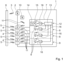
- Fig. 1 shows a block diagram of an exemplary embodiment of a light detection and ranging system 1 according to the present invention.
- the light detection and ranging system 1 comprises a first light source 2 for emitting a light signal to the surroundings of the light detection and ranging system 1.
- the first light source 2 is for example a laser source that emits laser pulses to the surroundings of the light detection and ranging system 1.
- the emitted light signal 3 hits objects 6 in the surroundings of the light detection and ranging system 1 and is reflected or scattered back to the light detection and ranging system 1. These light signals from the surroundings reflected or scattered back to the light detection and ranging system 1 are indicated in Fig. 1 by reference 5.
- the light detection and ranging system 1 further comprises multiple receiving optical sensors 4 for receiving the light signals 5 from the surroundings of the light detection and ranging system 1. These receiving optical sensors 4 are for example photodiodes. The receiving optical sensors 4 are for example arranged in the front part of a vehicle.
- the signals of the multiple receiving optical sensors 4 are processed by an optical receiver system 7 of the light detection and ranging system 1.
- An optical receiver system 7 of the light detection and ranging system 1 of Fig. 1 is shown in Fig. 2 .
- the optical receiver system 7 is preferably implemented in a single integrated circuit.
- the optical receiver system 7 comprises a separate receiver channel 8 for each receiving optical sensor 4.
- the separate receiver channels 8 are separated by dashed lines.
- Each separate receiver channel 8 comprises at least an amplifier 9 for amplifying the signal of the corresponding receiving optical sensor 4.
- the amplifiers 9 have an adjustable gain, to adjust the amplification of the signal of the corresponding receiving optical sensor 4.
- each receiver channel further comprises a signal processing block 16, which for example comprises a buffer, an analog-to-digital converter and/or a signal processing unit.
- the light detection and ranging system 1 further comprises a second light source 10, like a laser source, for emitting a light signal 11 directly to a reference receiver channel 12 of the optical receiver system 7 and the multiple receiving optical sensors 4.
- the reference receiver channel 12 comprises a reference optical sensor 14 and a reference amplifier 15.
- the reference receiver channel 12 also comprises a signal processing block 16 comprising a buffer, an analog-to-digital converter and/or a signal processing unit.
- the optical receiver system 7 further comprises a comparator 13 for comparing the output of the reference receiver channel 12 and the output of each of the separate receiver channels 8.
- the comparator 13 adjusts the gain of the amplifiers 9 of each separate receiver channel 8 based on the result of the comparison of the output of the reference receiver channel 12 and the output of the corresponding separate receiver channel 8.
- the comparator 13 adjusts the gain of the amplifiers of the separate receiver channels 8 in such a way, that the output of each separate receiver channel 8 corresponds to the output of the reference receiver channel 12.
- each separate receiver channel 8 provides the same output to the same light signal 11, i.e. the light signal 11 emitted by the second light source 10.
- the optical receiver system 7 comprises one comparator 13 for comparing the output of the reference receiver channel 12 and the output of each of the separate receiver channels 8. This comparison can be performed serially or at least partially in parallel.
- the comparator 13 is preferably part of the optical receiver system 7 but could also be a separate part of the light detection and ranging system 1.
Landscapes
- Engineering & Computer Science (AREA)
- Computer Networks & Wireless Communication (AREA)
- Physics & Mathematics (AREA)
- General Physics & Mathematics (AREA)
- Radar, Positioning & Navigation (AREA)
- Remote Sensing (AREA)
- Optical Radar Systems And Details Thereof (AREA)
Description
- The invention relates to a light detection and ranging system. The invention further relates to an optical receiver system for a light detection and ranging system and a method for operating a light detection and ranging system.
- Light detection and ranging (Lidar) systems, also called laser detection and ranging (Ladar) systems, measure the distance to a target by illuminating the target with pulsed laser light and measuring the reflected pulses with an optical sensor.
- Differences in laser return times and wavelength can then be used to make 3-D representations of the target. Lidar systems have become popular in automotive applications, for example in advanced safety systems. A lidar systems is for example used to scan the surroundings of a car to detect any obstacles on a collision course with the car and issue a warning to the driver and/or to initiate an emergency brake. Lidar systems are often used in autonomous cars for controlling and navigation purposes. In such automotive applications, it is essential that the Lidar systems is highly available and precise with a minimum of detection errors.
- The emitting system of the light detection and ranging system comprises a light source, particularly a laser source like a laser diode, for emitting the light signal to the surroundings of the light detection and ranging system.
- This emitting light signal is reflected or scattered by objects in the surroundings of the light detection and ranging system.
- The optical receiver system of the light detection and ranging system usually comprises or is connected to a string of optical sensors, which are for example arranged in the front part of an automobile. For example, the optical receiver system is arranged inside the automobile and connected to the string of optical sensors via a cable. The optical receiver system comprises at least one optical receiver channel, which is connectable to a respective optical sensor. Usually, the optical receiver system comprises a separate optical receiver channel for each optical sensor.
- The optical receiver system amplifies the signal of the optical sensor before processing the optical sensor signal. The amplified optical sensor signal is usually converted from the analog domain to the digital domain by an analog-to-digital converter and afterwards being processed by a digital signal processor. Therefore, each optical receiver channel comprises a separate amplifier system for amplifying the respective optical sensor signals.
- The different optical receiver channels of the optical receiver system ideally have matching amplification characteristics (gain), i.e. providing each the same result at the output in response to an identical current pulse from the optical sensor. Usually, the amplification characteristics are trimmed at low frequency, to ensure a good matching between the different optical receiver channels. However, another source of mismatch between the different optical receiver channels is represented by a mismatch in the optical sensors (photodiodes) responsivity, i.e. the ration of the generated current in response to incident light power. Thus, the output of the photo sensors in response to the same light intensity may differ from each other. This results in a different output, even for perfectly matched optical receiver channels.
- Since there is no guarantee that the optical sensors used in a light detection and ranging system are selected from lots of matched devices, this mismatch between different optical sensors cannot be avoided. Furthermore, this mismatch can also not be trimmed out for each optical receiver channel using ATE (Automated Test Equipment), as the optical sensors are normally added to the light detection and ranging system by the final customer, for example car manufacturer. In addition, different customers most likely use different optical sensors, resulting in a different behaviour of the same light detection and ranging system. Finally, the light detection and ranging system, particularly the optical sensors and/or amplifiers of the optical receiver channels, are aging respectively stressed over the lifetime and may lead to a further mismatch between the output of the optical receiver channels in response to identical inputs.
- On the other hand, high performance Lidar systems, as used in autonomous cars for controlling and navigation purposes, must be highly available with a minimum of detection errors and fulfil certain Automotive Safety Integrity Levels (ASILs), like e.g. an error below 9, 6 or 3 electrical degree.
- Light detection and ranging systems are for example disclosed in
US 4,068,222 A ,CH 695 516 A5 DE 24 03 052 A1 orUS 2021/223398 A1 . - It is therefore an object of the present invention to provide a light detection and ranging system which is highly available with a minimum of detection errors by eliminating receiver channel mismatch.
- The object is solved by a light detection and ranging system comprising:
- at least one first light source for emitting a light signal to the surroundings of the light detection and ranging system,
- multiple receiving optical sensors for receiving a light signal from the surroundings of the light detection and ranging system, and
- an optical receiver system for processing the signals of the multiple receiving optical sensors, wherein the optical receiver system comprises a separate receiver channel for each receiving optical sensor, each separate receiver channel comprising an amplifier with an adjustable gain for amplifying the signal of the corresponding receiving optical sensor,
- wherein the light detection and ranging system further comprises a second light source for emitting a light signal directly to a reference receiver channel and the multiple receiving optical sensors,
- wherein the optical receiver system comprises the reference receiver channel and at least one comparator for comparing the output of the reference receiver channel and the output of each of the separate receiver channels, the reference receiver channel comprising a reference optical sensor and a reference amplifier,
- and wherein the at least one comparator is configured to adjust the gain of the amplifiers of each separate receiver channel based on the result of the comparison of the output of the reference receiver channel and the output of the corresponding separate receiver channel.
- According to the present invention, a mismatch between the multiple receiver channels of the optical receiver system is avoided by comparing the output of each receiver channel to the output of a reference receiver channel. Based on this comparison, the gain of the amplifiers of the multiple receiver channels can be adjusted so that the output of each receiver channel corresponds to the output of the reference receiver channel. Since the reference optical sensor of the reference receiver channel and the optical sensors connected to the multiple receiver channels are illuminated by the same light signal emitted from the second light source, the multiple receiver channels provide identical output to the same light signal after the gains of the amplifiers of the receiver channels have been adjusted by the light detection and ranging system of the present invention.
- The present invention provides an online detection and correction of multiple sources of mismatch between different receiver channels of the optical receiver system in the overall receiver channel response during the whole lifetime of the light detection and ranging system. It ensures proper operation of the signal acquisition and processing channels of the light detection and ranging system with matched behaviour and thus higher predictability, accuracy and resolution. It further allows flexibility for the customers in choosing optical sensors like photodiodes, as the possible mismatches are detected and compensated during light detection and ranging system operation, regardless of the specific optical sensor responsivity.
- The emitted first light signal and/or the emitted second light signal is preferably a light pulse with a defined characteristic, particularly wavelength, duration and form. The first light signal and the second light signal can be identical or different.
- Pursuant to a variant of the invention, the multiple receiver channels and the reference receiver channel further comprise a buffer, an analog-to-digital converter and/or a signal processing unit, particularly digital signal processing unit. Particularly, the multiple receiver channels and the reference receiver channel each comprise the same elements. Since the output of each receiver channel is compared to the output of the reference receiver channel even mismatches due to the additional components is trimmed out by the present invention.
- According to an advantageous variant of the invention, the at least one first light source and the second light source are controlled by the light detection and ranging system and do not emit light simultaneously. Thus, an interference between both light signals is avoided, which further increases the accuracy of the light detection and ranging system. Particularly, the second light source emits light during dedicated time windows different from the time windows of the normal acquisition window, in which the at least one first light source emits light signals to the surroundings of the light detection and ranging system.
- In a variant of the invention, the light detection and ranging system comprises a separate comparator for each separate receiver channel, for comparing the output of the reference receiver channel to the output of the corresponding receiver channel. Thus, the output of each receiver channel can be compared to the output of the reference receiver channel in parallel, which reduces the necessary time to trim out the mismatch between the multiple receiver channel, particularly compared to a serial comparison of the output of the multiple receiver channels to the output of the reference receiver channel.
- According to a variant of the invention, the amplifier of each optical receiver channel and the reference receiver channel is a transimpedance amplifier. Additionally or alternatively, the receiving optical sensors of the multiple optical receiver channels and the reference receiver channel are photodiodes and/or the first light source and/or the second light source is a laser source.
- Pursuant to a further variant of the invention, the light detection and ranging system further comprises sender optics and/or receiver optics for adjusting light emitting characteristics and/or light receiving characteristics of the light detection and ranging system. The optics particularly refer to the emitting of the light signal from the at least one first light source to the surroundings of the light detection and ranging system and receiving light signal from the surroundings of the light detection and ranging system. The second light signal emitted from the second light source is preferably emitted directly within the light detection and ranging system to the optical sensors and reference optical sensor.
- In a preferred variant of the invention, the optical receiver system is implemented in an integrated circuit. Thus, all components of the optical receiver system are contained in a single integrated circuit (IC). This reduces susceptibility to external noise. The multiple receiver channels of this integrated circuit are for example connected to the optical sensors for receiving light signals from the surroundings of the light detection and ranging system. Alternatively, the optical sensors for receiving light signals from the surroundings of the light detection and ranging system can also be integrated into the integrated circuit.
- The object is further solved by an optical receiver system for a light detection and ranging system according to the present invention, wherein the optical receiver system comprises the reference receiver channel and at least one comparator for comparing the output of the reference receiver channel and the output of each of the separate receiver channels, the reference receiver channel comprising a reference optical sensor and a reference amplifier, and wherein the at least one comparator is configured to adjust the gain of the amplifiers of each separate receiver channel based on the result of the comparison of the output of the reference receiver channel and the output of the corresponding separate receiver channel. Thus, the optical receiver system provides all necessary components for comparing the output of the multiple receiver channels to the output of the reference receiver channel and adjust the gain of the amplifiers of the multiple receiver channels to trim out any mismatch between the multiple receiver channels. Other components of the light detection and ranging system, like e.g. the optical sensors, the first light source and/or second light source might be connected to the optical receiver channel at a later stage, e.g. at the customer site during assembly of a vehicle, due complete the light detection and ranging system.
- The object is further solved by a method for operating a light detection and ranging system comprising the steps of: emitting a first light signal to the surroundings of the light detection and ranging system,
- receiving a light signal from the surroundings of the light detection and ranging system using multiple receiving optical sensors,
- processing the signal of the receiving optical sensors by separate receiver channels of an optical receiver system of the light detection and ranging system, wherein the processing comprises at least amplifying the signal of the receiving optical sensors by the separate receiver channels,
- wherein the method further comprises the steps of:
- emitting a second light signal directly to a reference receiver channel and the multiple receiving optical sensors,
- comparing the output of the reference receiver channel and the output of each of the separate receiver channels,
- and adjusting the gain of the amplifiers of each separate receiver channel based on the result of the comparison of the output of the reference receiver channel and the output of the corresponding separate receiver channel.
- According to the present invention, a mismatch between the multiple receiver channels of the optical receiver system is avoided by comparing the output of each receiver channel to the output of a reference receiver channel. Based on this comparison, the gain of the amplifiers of the multiple receiver channels can be adjusted so that the output of each receiver channel corresponds to the output of the reference receiver channel. Since the reference optical sensor of the reference receiver channel and the optical sensors connected to the multiple receiver channels are illuminated by the same light signal emitted from the second light source, the multiple receiver channels provide identical output to the same light signal after the gains of the amplifiers of the receiver channels have been adjusted by the method of operating light detection and ranging system according to the present invention.
- The present invention provides an online detection and correction of multiple sources of mismatch between different receiver channels of the optical receiver system in the overall receiver channel response during the whole lifetime of the light detection and ranging system. It ensures proper operation of the signal acquisition and processing channels of the light detection and ranging system with matched behaviour and thus higher predictability, accuracy and resolution. It further allows flexibility for the customers in choosing optical sensors like photodiodes, as the possible mismatches are detected and compensated during light detection and ranging system operation, regardless of the specific optical sensor responsivity.
- The emitted first light signal and/or the emitted second light signal is preferably a light pulse with a defined characteristic, particularly wavelength, duration and form. The first light signal and the second light signal can be identical or different. Pursuant to a variant of the invention, the processing of the signal of the receiving optical sensors further comprises buffering the signal, converting the signal from the analog domain to the digital domain and/or digitally processing the signal. Particularly, the multiple receiver channels and the reference receiver channel each execute the same processing steps. Since the output of each receiver channel is compared to the output of the reference receiver channel even mismatches due to the additional processing steps is trimmed out by the present invention.
- According to an advantageous variant of the invention, the first light signal and the second light signal are not emitted simultaneously. Thus, an interference between both light signals is avoided, which further increases the accuracy of the method for operating a light detection and ranging system.
- Particularly, the second light source emits light during dedicated time windows different from the time windows of the normal acquisition window, in which the at least one first light source emits light signals to the surroundings of the light detection and ranging system.
- Pursuant to a further variant of the invention, the signal of the reference receiver channel and each optical receiver channel are compared in parallel, preferably by separate comparators. Since the output of each receiver channel is compared to the output of the reference receiver channel in parallel, the necessary time to trim out the mismatch between the multiple receiver channel is reduced, particularly compared to a serial comparison of the output of the multiple receiver channels to the output of the reference receiver channel.
- According to a variant of the invention, the method is performed continuously during operation of the light detection and ranging system. Since the method is performed continuously even a mismatch between the multiple receiver channels due to degradation over the lifetime of the light detection and ranging system can be trimmed out by the inventive method.
- Pursuant to a variant of the invention, the steps of emitting, comparing and adjusting, particularly the comparison between the output of the reference receiver channel and the output of the multiple receiver channels, is performed in predetermined intervals. It is sufficient to perform the inventive method in predetermined intervals as a mismatch between the multiple receiver channels is usually not a dynamic effect but only changing slowly over time.
- In the following, the invention will be further explained with respect to the embodiments shown in the figures. It shows:
- Fig. 1
- a block diagram of an embodiment of a light detection and ranging system according to the invention,
- Fig. 2
- a detailed view of the optical receiver system of
Fig. 1 , and - Fig. 3
- a detailed view of another embodiment of an optical receiver system.
-
Fig. 1 shows a block diagram of an exemplary embodiment of a light detection and rangingsystem 1 according to the present invention. - The light detection and ranging
system 1 comprises a firstlight source 2 for emitting a light signal to the surroundings of the light detection and rangingsystem 1. The firstlight source 2 is for example a laser source that emits laser pulses to the surroundings of the light detection and rangingsystem 1. - The emitted
light signal 3 hits objects 6 in the surroundings of the light detection and rangingsystem 1 and is reflected or scattered back to the light detection and rangingsystem 1. These light signals from the surroundings reflected or scattered back to the light detection and rangingsystem 1 are indicated inFig. 1 byreference 5. - The light detection and ranging
system 1 further comprises multiple receivingoptical sensors 4 for receiving the light signals 5 from the surroundings of the light detection and rangingsystem 1. These receivingoptical sensors 4 are for example photodiodes. The receivingoptical sensors 4 are for example arranged in the front part of a vehicle. - The signals of the multiple receiving
optical sensors 4 are processed by anoptical receiver system 7 of the light detection and rangingsystem 1. A detailed view of theoptical receiver system 7 of the light detection and rangingsystem 1 ofFig. 1 is shown inFig. 2 . Theoptical receiver system 7 is preferably implemented in a single integrated circuit. - The
optical receiver system 7 comprises aseparate receiver channel 8 for each receivingoptical sensor 4. InFigs. 1 and2 , theseparate receiver channels 8 are separated by dashed lines. Eachseparate receiver channel 8 comprises at least anamplifier 9 for amplifying the signal of the corresponding receivingoptical sensor 4. Theamplifiers 9 have an adjustable gain, to adjust the amplification of the signal of the corresponding receivingoptical sensor 4. According to the embodiment shown inFig. 1 , each receiver channel further comprises asignal processing block 16, which for example comprises a buffer, an analog-to-digital converter and/or a signal processing unit. - According to the present invention, the light detection and ranging
system 1 further comprises a secondlight source 10, like a laser source, for emitting alight signal 11 directly to areference receiver channel 12 of theoptical receiver system 7 and the multiple receivingoptical sensors 4. Thereference receiver channel 12 comprises a referenceoptical sensor 14 and areference amplifier 15. Like theseparate receiver channels 8, thereference receiver channel 12 also comprises asignal processing block 16 comprising a buffer, an analog-to-digital converter and/or a signal processing unit. - The
optical receiver system 7 further comprises acomparator 13 for comparing the output of thereference receiver channel 12 and the output of each of theseparate receiver channels 8. Thecomparator 13 adjusts the gain of theamplifiers 9 of eachseparate receiver channel 8 based on the result of the comparison of the output of thereference receiver channel 12 and the output of the correspondingseparate receiver channel 8. Thecomparator 13 adjusts the gain of the amplifiers of theseparate receiver channels 8 in such a way, that the output of eachseparate receiver channel 8 corresponds to the output of thereference receiver channel 12. Thus, eachseparate receiver channel 8 provides the same output to thesame light signal 11, i.e. thelight signal 11 emitted by the secondlight source 10. - According to the embodiment shown in
Figs. 1 and2 , theoptical receiver system 7 comprises onecomparator 13 for comparing the output of thereference receiver channel 12 and the output of each of theseparate receiver channels 8. This comparison can be performed serially or at least partially in parallel. Thecomparator 13 is preferably part of theoptical receiver system 7 but could also be a separate part of the light detection and rangingsystem 1. - The first
light source 2 and the secondlight source 10 are controlled by the light detection and rangingsystem 1 and do not emit light simultaneously. Thus, an interference between the emitted light signals 3 and 11 and processing of the light signals 5 from the surroundings andlight signals 11 from the secondlight source 10 can be avoided. - The
amplifiers 9 of theseparate receiver channels 8 and thereference amplifier 15 of thereference receiver channel 12 are for example transimpedance amplifiers. The receivingoptical sensors 4 of theseparate receiver channels 8 and the referenceoptical sensor 14 of thereference receiver channel 12 are for example photodiodes. - The light detection and ranging
system 1 can further comprise sender optics and/or receiver optics (not shown) for adjusting light emitting characteristics and/or light receiving characteristics of the light detection and rangingsystem 1. -
Fig. 3 shows a detailed view of another embodiment of anoptical receiver system 7. Theoptical receiver system 7 shown inFig. 3 differs from theoptical receiver system 7 shown inFig. 2 in that theoptical receiver system 7 comprises aseparate comparator 13 for eachseparate receiver channel 8. Thus, the outputs of allseparate receiver channels 8 can be compared fully in parallel to the output of thereference receiver channel 12 by themultiple comparators 13. Again, thecomparators 13 are not necessarily part of theoptical receiver system 7 but could also be a separate part of the light detection and rangingsystem 1. With respect to all other features theoptical receiver system 7 ofFig. 3 corresponds to theoptical receiver system 7 ofFig. 2 and can be for example used in a light detection and rangingsystem 1 as shown inFig. 1 . -
- 1
- light detection and ranging system
- 2
- first light source
- 3
- emitted light signal (first light source)
- 4
- receiving optical sensor
- 5
- light signal from the surroundings of the light detection and ranging system
- 6
- object
- 7
- optical receiver system
- 8
- receiver channel
- 9
- amplifier
- 10
- second light source
- 11
- emitted light signal (second light source)
- 12
- reference receiver channel
- 13
- comparator
- 14
- reference optical sensor
- 15
- reference amplifier
- 16
- signal processing block (buffer, ADC, CPU)
Claims (15)
- A light detection and ranging system (1) comprising:at least one first light source (2) for emitting a light signal (3) to the surroundings of the light detection and ranging system (1),multiple receiving optical sensors (4) for receiving a light signal (5) from the surroundings of the light detection and ranging system (1), andan optical receiver system (7) for processing the signals of the multiple receiving optical sensors (4), wherein the optical receiver system (7) comprises a separate receiver channel (8) for each receiving optical sensor (4), each separate receiver channel (8) comprising an amplifier (9) with an adjustable gain for amplifying the signal of the corresponding receiving optical sensor (4),wherein the light detection and ranging system (1) further comprises a second light source (10) for emitting a light signal (11) directly to a reference receiver channel (12) and the multiple receiving optical sensors (4),wherein the optical receiver system (7) comprises the reference receiver channel (12) and at least one comparator (13) for comparing the output of the reference receiver channel (12) and the output of each of the separate receiver channels (8), the reference receiver channel (12) comprising a reference optical sensor (14) and a reference amplifier (15),and wherein the at least one comparator (13) is configured to adjust the gain of the amplifiers (9) of each separate receiver channel (8) based on the result of the comparison of the output of the reference receiver channel (12) and the output of the corresponding separate receiver channel (8).
- The light detection and ranging system (1) according to claim 1,
wherein the multiple receiver channels (8) and the reference receiver channel (12) further comprise a buffer, an analog-to-digital converter and/or a signal processing unit. - The light detection and ranging system (1) according to claim 1 or claim 2,
wherein the at least one first light source (2) and the second light source (10) are controlled by the light detection and ranging system (1) and do not emit light simultaneously. - The light detection and ranging system (1) according to any of claims 1 to 3,
comprising a separate comparator (13) for each separate receiver channel (8), for comparing the output of the reference receiver channel (12) to the output of the corresponding receiver channel (8). - The light detection and ranging system (1) according to any of claims 1 to 4,
wherein the amplifier (9, 15) of each optical receiver channel (8) and the reference receiver channel (12) is a transimpedance amplifier. - The light detection and ranging system (1) according to any of claims 1 to 5,
wherein the receiving optical sensors (4, 14) of the multiple optical receiver channels (8) and the reference receiver channel (12) are photodiodes and/or the first light source (2) and/or the second light source (10) is a laser source. - The light detection and ranging system (1) according to any of claims 1 to 6,
further comprising sender optics and/or receiver optics for adjusting light emitting characteristics and/or light receiving characteristics of the light detection and ranging system (1). - The light detection and ranging system (1) according to any of claims 1 to 7,
wherein the optical receiver system (7) is implemented in an integrated circuit. - An optical receiver system (7) for a light detection and ranging system (1) according to any of claims 1 to 8,
whereinthe optical receiver system (7) comprises the reference receiver channel (12) and at least one comparator (13) for comparing the output of the reference receiver channel (12) and the output of each of the separate receiver channels (8), the reference receiver channel (12) comprising a reference optical sensor (14) and a reference amplifier (15),and wherein the at least one comparator (13) is configured to adjust the gain of the amplifiers (9) of each separate receiver channel (8) based on the result of the comparison of the output of the reference receiver channel (12) and the output of the corresponding separate receiver channel (8). - A method for operating a light detection and ranging system (1) comprising the steps of:emitting a first light signal (3) to the surroundings of the light detection and ranging system (1),receiving a light signal (5) from the surroundings of the light detection and ranging system (1) using multiple receiving optical sensors (4),processing the signal of the receiving optical sensors (4) by separate receiver channels (8) of an optical receiver system (7) of the light detection and ranging system (1), wherein the processing comprises at least amplifying the signal of the receiving optical sensors (4) by the separate receiver channels (8),wherein the method further comprises the steps of:emitting a second light signal (11) directly to a reference receiver channel (12) and the multiple receiving optical sensors (4),comparing the output of the reference receiver channel (12) and the output of each of the separate receiver channels (8),and adjusting the gain of the amplifiers (9) of each separate receiver channel (8) based on the result of the comparison of the output of the reference receiver channel (12) and the output of the corresponding separate receiver channel (8).
- The method according to claim 10,
wherein the processing of the signal of the receiving optical sensors (4) further comprises buffering the signal, converting the signal from an analog domain to the digital domain and/or digitally processing the signal. - The method according to claim 10 or claim 11,
wherein the first light signal (3) and the second light signal (11) are not emitted simultaneously. - The method according to any of claims 10 to 12,
wherein the signal of the reference receiver channel (12) and each optical receiver channel (8) are compared in parallel. - The method according to any of claims 10 to 13,
wherein the method is performed continuously during operation of the light detection and ranging system (1). - The method according to any of claims 10 to 14,
wherein the steps emitting, comparing and adjusting are performed in predetermined intervals.
Priority Applications (3)
| Application Number | Priority Date | Filing Date | Title |
|---|---|---|---|
| EP21200173.9A EP4160264B1 (en) | 2021-09-30 | 2021-09-30 | Lidar system with reference receiver channel, suitable optical receiver and corresponding lidar operating method |
| CN202211149138.9A CN115902822A (en) | 2021-09-30 | 2022-09-20 | Light detection and ranging system, method of operating the same, and optical receiver system for the same |
| US17/952,435 US20230098843A1 (en) | 2021-09-30 | 2022-09-26 | Light detection and ranging system, optical receiver system for a light detection and ranging system and method for operating a light detection and ranging system |
Applications Claiming Priority (1)
| Application Number | Priority Date | Filing Date | Title |
|---|---|---|---|
| EP21200173.9A EP4160264B1 (en) | 2021-09-30 | 2021-09-30 | Lidar system with reference receiver channel, suitable optical receiver and corresponding lidar operating method |
Publications (2)
| Publication Number | Publication Date |
|---|---|
| EP4160264A1 EP4160264A1 (en) | 2023-04-05 |
| EP4160264B1 true EP4160264B1 (en) | 2025-04-16 |
Family
ID=78134821
Family Applications (1)
| Application Number | Title | Priority Date | Filing Date |
|---|---|---|---|
| EP21200173.9A Active EP4160264B1 (en) | 2021-09-30 | 2021-09-30 | Lidar system with reference receiver channel, suitable optical receiver and corresponding lidar operating method |
Country Status (3)
| Country | Link |
|---|---|
| US (1) | US20230098843A1 (en) |
| EP (1) | EP4160264B1 (en) |
| CN (1) | CN115902822A (en) |
Families Citing this family (1)
| Publication number | Priority date | Publication date | Assignee | Title |
|---|---|---|---|---|
| DE102023003375A1 (en) | 2023-08-16 | 2025-02-20 | Michael Dietmar Pierschel | LIDAR system with increased reliability |
Family Cites Families (3)
| Publication number | Priority date | Publication date | Assignee | Title |
|---|---|---|---|---|
| DE2452794C3 (en) * | 1974-11-07 | 1979-08-30 | Philips Patentverwaltung Gmbh, 2000 Hamburg | Automatic level adjustment circuit for presettable IR pulse monitoring devices with clocked receiver |
| CH695516A5 (en) * | 2001-02-05 | 2006-06-15 | Hilti Ag | Optoelectronic distance measurement in construction and plant engineering industry, involves modulating optical intensities of main and reference emitters, and determining phase of resultant signals simultaneously |
| US12085649B2 (en) * | 2020-01-21 | 2024-09-10 | Semiconductor Components Industries, Llc | Imaging systems with single-photon avalanche diodes and ambient light level detection |
-
2021
- 2021-09-30 EP EP21200173.9A patent/EP4160264B1/en active Active
-
2022
- 2022-09-20 CN CN202211149138.9A patent/CN115902822A/en active Pending
- 2022-09-26 US US17/952,435 patent/US20230098843A1/en active Pending
Also Published As
| Publication number | Publication date |
|---|---|
| CN115902822A (en) | 2023-04-04 |
| EP4160264A1 (en) | 2023-04-05 |
| US20230098843A1 (en) | 2023-03-30 |
Similar Documents
| Publication | Publication Date | Title |
|---|---|---|
| US11125863B2 (en) | Correction device, correction method, and distance measuring device | |
| US9696425B2 (en) | Optical distance measuring apparatus | |
| CN108344984B (en) | Light detection and ranging system | |
| US10852401B2 (en) | Distance measurement apparatus and distance measurement method | |
| US11280888B2 (en) | Low noise frontends for LiDAR receiver and methods for controlling the same comprising a multiplexing circuit for selectively connecting each photodetector to a shared amplifier | |
| US11378687B2 (en) | Distance measurement apparatus and distance measurement method | |
| US10754013B2 (en) | Method and control unit for controlling an emitted light output of a light source of an optical sensor system | |
| US8831908B2 (en) | Signal processing apparatus used for operations for range finding and scanning rangefinder | |
| JPH09199750A (en) | Device and method for detecting light pulse from a plurality of visual fields | |
| CN111492261B (en) | Laser receiving circuit, distance measuring device and mobile platform | |
| CN114966602A (en) | Lidar noise removal device and lidar noise removal method | |
| US20230098843A1 (en) | Light detection and ranging system, optical receiver system for a light detection and ranging system and method for operating a light detection and ranging system | |
| JP2016170053A (en) | Laser radar device | |
| US8477291B2 (en) | System and method for ranging of targets | |
| EP3640669B1 (en) | Solid-state optical receiver driver system and method for testing a solid-state optical receiver driver system | |
| US11782143B2 (en) | Light detection and ranging system and method for operating a light detection and ranging system | |
| KR20020089414A (en) | Device and method for detecting an object or a person in the passenger compartment of a vehicle | |
| JP2020076763A5 (en) | ||
| JP3651412B2 (en) | Distance measuring device and distance measuring method | |
| EP4036598A1 (en) | Method for testing of an optical receiver system, particularly of a light detection and ranging system | |
| EP3832345A1 (en) | Optical receiver system and method for operating an optical receiver system, particularly of a light detection and ranging system | |
| EP3754368A1 (en) | Amplifier system and method for operating an amplifier system, particularly for an optical receiver system of a light detection and ranging system | |
| EP3805791A1 (en) | Optical receiver system and method for operating an optical receiver system, particularly of a light detection and ranging system |
Legal Events
| Date | Code | Title | Description |
|---|---|---|---|
| PUAI | Public reference made under article 153(3) epc to a published international application that has entered the european phase |
Free format text: ORIGINAL CODE: 0009012 |
|
| STAA | Information on the status of an ep patent application or granted ep patent |
Free format text: STATUS: THE APPLICATION HAS BEEN PUBLISHED |
|
| AK | Designated contracting states |
Kind code of ref document: A1 Designated state(s): AL AT BE BG CH CY CZ DE DK EE ES FI FR GB GR HR HU IE IS IT LI LT LU LV MC MK MT NL NO PL PT RO RS SE SI SK SM TR |
|
| STAA | Information on the status of an ep patent application or granted ep patent |
Free format text: STATUS: REQUEST FOR EXAMINATION WAS MADE |
|
| 17P | Request for examination filed |
Effective date: 20230919 |
|
| RBV | Designated contracting states (corrected) |
Designated state(s): AL AT BE BG CH CY CZ DE DK EE ES FI FR GB GR HR HU IE IS IT LI LT LU LV MC MK MT NL NO PL PT RO RS SE SI SK SM TR |
|
| GRAP | Despatch of communication of intention to grant a patent |
Free format text: ORIGINAL CODE: EPIDOSNIGR1 |
|
| STAA | Information on the status of an ep patent application or granted ep patent |
Free format text: STATUS: GRANT OF PATENT IS INTENDED |
|
| RIC1 | Information provided on ipc code assigned before grant |
Ipc: G01S 7/497 20060101ALI20241021BHEP Ipc: G01S 7/489 20060101AFI20241021BHEP |
|
| INTG | Intention to grant announced |
Effective date: 20241030 |
|
| GRAJ | Information related to disapproval of communication of intention to grant by the applicant or resumption of examination proceedings by the epo deleted |
Free format text: ORIGINAL CODE: EPIDOSDIGR1 |
|
| STAA | Information on the status of an ep patent application or granted ep patent |
Free format text: STATUS: REQUEST FOR EXAMINATION WAS MADE |
|
| GRAP | Despatch of communication of intention to grant a patent |
Free format text: ORIGINAL CODE: EPIDOSNIGR1 |
|
| STAA | Information on the status of an ep patent application or granted ep patent |
Free format text: STATUS: GRANT OF PATENT IS INTENDED |
|
| INTC | Intention to grant announced (deleted) | ||
| GRAS | Grant fee paid |
Free format text: ORIGINAL CODE: EPIDOSNIGR3 |
|
| GRAA | (expected) grant |
Free format text: ORIGINAL CODE: 0009210 |
|
| STAA | Information on the status of an ep patent application or granted ep patent |
Free format text: STATUS: THE PATENT HAS BEEN GRANTED |
|
| INTG | Intention to grant announced |
Effective date: 20250219 |
|
| AK | Designated contracting states |
Kind code of ref document: B1 Designated state(s): AL AT BE BG CH CY CZ DE DK EE ES FI FR GB GR HR HU IE IS IT LI LT LU LV MC MK MT NL NO PL PT RO RS SE SI SK SM TR |
|
| REG | Reference to a national code |
Ref country code: GB Ref legal event code: FG4D |
|
| REG | Reference to a national code |
Ref country code: CH Ref legal event code: EP Ref country code: DE Ref legal event code: R096 Ref document number: 602021029165 Country of ref document: DE |
|
| REG | Reference to a national code |
Ref country code: IE Ref legal event code: FG4D |
|
| REG | Reference to a national code |
Ref country code: NL Ref legal event code: MP Effective date: 20250416 |
|
| PG25 | Lapsed in a contracting state [announced via postgrant information from national office to epo] |
Ref country code: NL Free format text: LAPSE BECAUSE OF FAILURE TO SUBMIT A TRANSLATION OF THE DESCRIPTION OR TO PAY THE FEE WITHIN THE PRESCRIBED TIME-LIMIT Effective date: 20250416 |
|
| REG | Reference to a national code |
Ref country code: AT Ref legal event code: MK05 Ref document number: 1786080 Country of ref document: AT Kind code of ref document: T Effective date: 20250416 |
|
| PG25 | Lapsed in a contracting state [announced via postgrant information from national office to epo] |
Ref country code: PT Free format text: LAPSE BECAUSE OF FAILURE TO SUBMIT A TRANSLATION OF THE DESCRIPTION OR TO PAY THE FEE WITHIN THE PRESCRIBED TIME-LIMIT Effective date: 20250818 Ref country code: ES Free format text: LAPSE BECAUSE OF FAILURE TO SUBMIT A TRANSLATION OF THE DESCRIPTION OR TO PAY THE FEE WITHIN THE PRESCRIBED TIME-LIMIT Effective date: 20250416 Ref country code: FI Free format text: LAPSE BECAUSE OF FAILURE TO SUBMIT A TRANSLATION OF THE DESCRIPTION OR TO PAY THE FEE WITHIN THE PRESCRIBED TIME-LIMIT Effective date: 20250416 |
|
| PGFP | Annual fee paid to national office [announced via postgrant information from national office to epo] |
Ref country code: DE Payment date: 20250926 Year of fee payment: 5 |
|
| REG | Reference to a national code |
Ref country code: LT Ref legal event code: MG9D |
|
| PG25 | Lapsed in a contracting state [announced via postgrant information from national office to epo] |
Ref country code: NO Free format text: LAPSE BECAUSE OF FAILURE TO SUBMIT A TRANSLATION OF THE DESCRIPTION OR TO PAY THE FEE WITHIN THE PRESCRIBED TIME-LIMIT Effective date: 20250716 Ref country code: GR Free format text: LAPSE BECAUSE OF FAILURE TO SUBMIT A TRANSLATION OF THE DESCRIPTION OR TO PAY THE FEE WITHIN THE PRESCRIBED TIME-LIMIT Effective date: 20250717 |
|
| PG25 | Lapsed in a contracting state [announced via postgrant information from national office to epo] |
Ref country code: PL Free format text: LAPSE BECAUSE OF FAILURE TO SUBMIT A TRANSLATION OF THE DESCRIPTION OR TO PAY THE FEE WITHIN THE PRESCRIBED TIME-LIMIT Effective date: 20250416 |
|
| PG25 | Lapsed in a contracting state [announced via postgrant information from national office to epo] |
Ref country code: BG Free format text: LAPSE BECAUSE OF FAILURE TO SUBMIT A TRANSLATION OF THE DESCRIPTION OR TO PAY THE FEE WITHIN THE PRESCRIBED TIME-LIMIT Effective date: 20250416 |
|
| PG25 | Lapsed in a contracting state [announced via postgrant information from national office to epo] |
Ref country code: HR Free format text: LAPSE BECAUSE OF FAILURE TO SUBMIT A TRANSLATION OF THE DESCRIPTION OR TO PAY THE FEE WITHIN THE PRESCRIBED TIME-LIMIT Effective date: 20250416 |
|
| PG25 | Lapsed in a contracting state [announced via postgrant information from national office to epo] |
Ref country code: AT Free format text: LAPSE BECAUSE OF FAILURE TO SUBMIT A TRANSLATION OF THE DESCRIPTION OR TO PAY THE FEE WITHIN THE PRESCRIBED TIME-LIMIT Effective date: 20250416 |
|
| PG25 | Lapsed in a contracting state [announced via postgrant information from national office to epo] |
Ref country code: RS Free format text: LAPSE BECAUSE OF FAILURE TO SUBMIT A TRANSLATION OF THE DESCRIPTION OR TO PAY THE FEE WITHIN THE PRESCRIBED TIME-LIMIT Effective date: 20250716 |
|
| PG25 | Lapsed in a contracting state [announced via postgrant information from national office to epo] |
Ref country code: IS Free format text: LAPSE BECAUSE OF FAILURE TO SUBMIT A TRANSLATION OF THE DESCRIPTION OR TO PAY THE FEE WITHIN THE PRESCRIBED TIME-LIMIT Effective date: 20250816 |
|
| PG25 | Lapsed in a contracting state [announced via postgrant information from national office to epo] |
Ref country code: LV Free format text: LAPSE BECAUSE OF FAILURE TO SUBMIT A TRANSLATION OF THE DESCRIPTION OR TO PAY THE FEE WITHIN THE PRESCRIBED TIME-LIMIT Effective date: 20250416 |
|
| PG25 | Lapsed in a contracting state [announced via postgrant information from national office to epo] |
Ref country code: DK Free format text: LAPSE BECAUSE OF FAILURE TO SUBMIT A TRANSLATION OF THE DESCRIPTION OR TO PAY THE FEE WITHIN THE PRESCRIBED TIME-LIMIT Effective date: 20250416 Ref country code: SM Free format text: LAPSE BECAUSE OF FAILURE TO SUBMIT A TRANSLATION OF THE DESCRIPTION OR TO PAY THE FEE WITHIN THE PRESCRIBED TIME-LIMIT Effective date: 20250416 |
|
| REG | Reference to a national code |
Ref country code: DE Ref legal event code: R097 Ref document number: 602021029165 Country of ref document: DE |
|
| PG25 | Lapsed in a contracting state [announced via postgrant information from national office to epo] |
Ref country code: CZ Free format text: LAPSE BECAUSE OF FAILURE TO SUBMIT A TRANSLATION OF THE DESCRIPTION OR TO PAY THE FEE WITHIN THE PRESCRIBED TIME-LIMIT Effective date: 20250416 |
|
| PG25 | Lapsed in a contracting state [announced via postgrant information from national office to epo] |
Ref country code: EE Free format text: LAPSE BECAUSE OF FAILURE TO SUBMIT A TRANSLATION OF THE DESCRIPTION OR TO PAY THE FEE WITHIN THE PRESCRIBED TIME-LIMIT Effective date: 20250416 |
|
| PG25 | Lapsed in a contracting state [announced via postgrant information from national office to epo] |
Ref country code: SK Free format text: LAPSE BECAUSE OF FAILURE TO SUBMIT A TRANSLATION OF THE DESCRIPTION OR TO PAY THE FEE WITHIN THE PRESCRIBED TIME-LIMIT Effective date: 20250416 |
|
| PG25 | Lapsed in a contracting state [announced via postgrant information from national office to epo] |
Ref country code: IT Free format text: LAPSE BECAUSE OF FAILURE TO SUBMIT A TRANSLATION OF THE DESCRIPTION OR TO PAY THE FEE WITHIN THE PRESCRIBED TIME-LIMIT Effective date: 20250416 |
|
| PG25 | Lapsed in a contracting state [announced via postgrant information from national office to epo] |
Ref country code: RO Free format text: LAPSE BECAUSE OF FAILURE TO SUBMIT A TRANSLATION OF THE DESCRIPTION OR TO PAY THE FEE WITHIN THE PRESCRIBED TIME-LIMIT Effective date: 20250416 |
|
| PLBE | No opposition filed within time limit |
Free format text: ORIGINAL CODE: 0009261 |
|
| STAA | Information on the status of an ep patent application or granted ep patent |
Free format text: STATUS: NO OPPOSITION FILED WITHIN TIME LIMIT |
|
| REG | Reference to a national code |
Ref country code: CH Ref legal event code: L10 Free format text: ST27 STATUS EVENT CODE: U-0-0-L10-L00 (AS PROVIDED BY THE NATIONAL OFFICE) Effective date: 20260225 |
|
| 26N | No opposition filed |
Effective date: 20260119 |
|
| REG | Reference to a national code |
Ref country code: CH Ref legal event code: H13 Free format text: ST27 STATUS EVENT CODE: U-0-0-H10-H13 (AS PROVIDED BY THE NATIONAL OFFICE) Effective date: 20260425 |