EP4160264B1 - Lidar-system mit referenz-empfangskanal, geeigneter optischer empfänger und entsprechendes lidar-betriebsverfahren - Google Patents
Lidar-system mit referenz-empfangskanal, geeigneter optischer empfänger und entsprechendes lidar-betriebsverfahren Download PDFInfo
- Publication number
- EP4160264B1 EP4160264B1 EP21200173.9A EP21200173A EP4160264B1 EP 4160264 B1 EP4160264 B1 EP 4160264B1 EP 21200173 A EP21200173 A EP 21200173A EP 4160264 B1 EP4160264 B1 EP 4160264B1
- Authority
- EP
- European Patent Office
- Prior art keywords
- receiver channel
- light
- light detection
- ranging system
- receiver
- Prior art date
- Legal status (The legal status is an assumption and is not a legal conclusion. Google has not performed a legal analysis and makes no representation as to the accuracy of the status listed.)
- Active
Links
Images

Classifications
-
- G—PHYSICS
- G01—MEASURING; TESTING
- G01S—RADIO DIRECTION-FINDING; RADIO NAVIGATION; DETERMINING DISTANCE OR VELOCITY BY USE OF RADIO WAVES; LOCATING OR PRESENCE-DETECTING BY USE OF THE REFLECTION OR RERADIATION OF RADIO WAVES; ANALOGOUS ARRANGEMENTS USING OTHER WAVES
- G01S7/00—Details of systems according to groups G01S13/00, G01S15/00, G01S17/00
- G01S7/48—Details of systems according to groups G01S13/00, G01S15/00, G01S17/00 of systems according to group G01S17/00
- G01S7/483—Details of pulse systems
- G01S7/486—Receivers
- G01S7/489—Gain of receiver varied automatically during pulse-recurrence period
-
- G—PHYSICS
- G01—MEASURING; TESTING
- G01S—RADIO DIRECTION-FINDING; RADIO NAVIGATION; DETERMINING DISTANCE OR VELOCITY BY USE OF RADIO WAVES; LOCATING OR PRESENCE-DETECTING BY USE OF THE REFLECTION OR RERADIATION OF RADIO WAVES; ANALOGOUS ARRANGEMENTS USING OTHER WAVES
- G01S7/00—Details of systems according to groups G01S13/00, G01S15/00, G01S17/00
- G01S7/48—Details of systems according to groups G01S13/00, G01S15/00, G01S17/00 of systems according to group G01S17/00
- G01S7/481—Constructional features, e.g. arrangements of optical elements
- G01S7/4814—Constructional features, e.g. arrangements of optical elements of transmitters alone
- G01S7/4815—Constructional features, e.g. arrangements of optical elements of transmitters alone using multiple transmitters
-
- G—PHYSICS
- G01—MEASURING; TESTING
- G01S—RADIO DIRECTION-FINDING; RADIO NAVIGATION; DETERMINING DISTANCE OR VELOCITY BY USE OF RADIO WAVES; LOCATING OR PRESENCE-DETECTING BY USE OF THE REFLECTION OR RERADIATION OF RADIO WAVES; ANALOGOUS ARRANGEMENTS USING OTHER WAVES
- G01S7/00—Details of systems according to groups G01S13/00, G01S15/00, G01S17/00
- G01S7/48—Details of systems according to groups G01S13/00, G01S15/00, G01S17/00 of systems according to group G01S17/00
- G01S7/481—Constructional features, e.g. arrangements of optical elements
- G01S7/4816—Constructional features, e.g. arrangements of optical elements of receivers alone
-
- G—PHYSICS
- G01—MEASURING; TESTING
- G01S—RADIO DIRECTION-FINDING; RADIO NAVIGATION; DETERMINING DISTANCE OR VELOCITY BY USE OF RADIO WAVES; LOCATING OR PRESENCE-DETECTING BY USE OF THE REFLECTION OR RERADIATION OF RADIO WAVES; ANALOGOUS ARRANGEMENTS USING OTHER WAVES
- G01S7/00—Details of systems according to groups G01S13/00, G01S15/00, G01S17/00
- G01S7/48—Details of systems according to groups G01S13/00, G01S15/00, G01S17/00 of systems according to group G01S17/00
- G01S7/497—Means for monitoring or calibrating
-
- G—PHYSICS
- G01—MEASURING; TESTING
- G01S—RADIO DIRECTION-FINDING; RADIO NAVIGATION; DETERMINING DISTANCE OR VELOCITY BY USE OF RADIO WAVES; LOCATING OR PRESENCE-DETECTING BY USE OF THE REFLECTION OR RERADIATION OF RADIO WAVES; ANALOGOUS ARRANGEMENTS USING OTHER WAVES
- G01S17/00—Systems using the reflection or reradiation of electromagnetic waves other than radio waves, e.g. lidar systems
- G01S17/88—Lidar systems specially adapted for specific applications
- G01S17/93—Lidar systems specially adapted for specific applications for anti-collision purposes
- G01S17/931—Lidar systems specially adapted for specific applications for anti-collision purposes of land vehicles
Definitions
- the invention relates to a light detection and ranging system.
- the invention further relates to an optical receiver system for a light detection and ranging system and a method for operating a light detection and ranging system.
- Light detection and ranging (Lidar) systems also called laser detection and ranging (Ladar) systems, measure the distance to a target by illuminating the target with pulsed laser light and measuring the reflected pulses with an optical sensor.
- Lidar Light detection and ranging
- Laser laser detection and ranging
- Lidar systems have become popular in automotive applications, for example in advanced safety systems.
- a lidar systems is for example used to scan the surroundings of a car to detect any obstacles on a collision course with the car and issue a warning to the driver and/or to initiate an emergency brake.
- Lidar systems are often used in autonomous cars for controlling and navigation purposes. In such automotive applications, it is essential that the Lidar systems is highly available and precise with a minimum of detection errors.
- the emitting system of the light detection and ranging system comprises a light source, particularly a laser source like a laser diode, for emitting the light signal to the surroundings of the light detection and ranging system.
- This emitting light signal is reflected or scattered by objects in the surroundings of the light detection and ranging system.
- the optical receiver system of the light detection and ranging system usually comprises or is connected to a string of optical sensors, which are for example arranged in the front part of an automobile.
- the optical receiver system is arranged inside the automobile and connected to the string of optical sensors via a cable.
- the optical receiver system comprises at least one optical receiver channel, which is connectable to a respective optical sensor.
- the optical receiver system comprises a separate optical receiver channel for each optical sensor.
- the optical receiver system amplifies the signal of the optical sensor before processing the optical sensor signal.
- the amplified optical sensor signal is usually converted from the analog domain to the digital domain by an analog-to-digital converter and afterwards being processed by a digital signal processor. Therefore, each optical receiver channel comprises a separate amplifier system for amplifying the respective optical sensor signals.
- the different optical receiver channels of the optical receiver system ideally have matching amplification characteristics (gain), i.e. providing each the same result at the output in response to an identical current pulse from the optical sensor.
- gain amplification characteristics
- the amplification characteristics are trimmed at low frequency, to ensure a good matching between the different optical receiver channels.
- another source of mismatch between the different optical receiver channels is represented by a mismatch in the optical sensors (photodiodes) responsivity, i.e. the ration of the generated current in response to incident light power.
- the output of the photo sensors in response to the same light intensity may differ from each other. This results in a different output, even for perfectly matched optical receiver channels.
- a light detection and ranging system comprising:
- the emitted first light signal and/or the emitted second light signal is preferably a light pulse with a defined characteristic, particularly wavelength, duration and form.
- the first light signal and the second light signal can be identical or different.
- the multiple receiver channels and the reference receiver channel further comprise a buffer, an analog-to-digital converter and/or a signal processing unit, particularly digital signal processing unit.
- the multiple receiver channels and the reference receiver channel each comprise the same elements. Since the output of each receiver channel is compared to the output of the reference receiver channel even mismatches due to the additional components is trimmed out by the present invention.
- the at least one first light source and the second light source are controlled by the light detection and ranging system and do not emit light simultaneously.
- the second light source emits light during dedicated time windows different from the time windows of the normal acquisition window, in which the at least one first light source emits light signals to the surroundings of the light detection and ranging system.
- the light detection and ranging system comprises a separate comparator for each separate receiver channel, for comparing the output of the reference receiver channel to the output of the corresponding receiver channel.
- the output of each receiver channel can be compared to the output of the reference receiver channel in parallel, which reduces the necessary time to trim out the mismatch between the multiple receiver channel, particularly compared to a serial comparison of the output of the multiple receiver channels to the output of the reference receiver channel.
- the optical receiver system is implemented in an integrated circuit.
- all components of the optical receiver system are contained in a single integrated circuit (IC). This reduces susceptibility to external noise.
- the multiple receiver channels of this integrated circuit are for example connected to the optical sensors for receiving light signals from the surroundings of the light detection and ranging system.
- the optical sensors for receiving light signals from the surroundings of the light detection and ranging system can also be integrated into the integrated circuit.
- the object is further solved by a method for operating a light detection and ranging system comprising the steps of: emitting a first light signal to the surroundings of the light detection and ranging system,
- the present invention provides an online detection and correction of multiple sources of mismatch between different receiver channels of the optical receiver system in the overall receiver channel response during the whole lifetime of the light detection and ranging system. It ensures proper operation of the signal acquisition and processing channels of the light detection and ranging system with matched behaviour and thus higher predictability, accuracy and resolution. It further allows flexibility for the customers in choosing optical sensors like photodiodes, as the possible mismatches are detected and compensated during light detection and ranging system operation, regardless of the specific optical sensor responsivity.
- the emitted first light signal and/or the emitted second light signal is preferably a light pulse with a defined characteristic, particularly wavelength, duration and form.
- the first light signal and the second light signal can be identical or different.
- the processing of the signal of the receiving optical sensors further comprises buffering the signal, converting the signal from the analog domain to the digital domain and/or digitally processing the signal.
- the multiple receiver channels and the reference receiver channel each execute the same processing steps. Since the output of each receiver channel is compared to the output of the reference receiver channel even mismatches due to the additional processing steps is trimmed out by the present invention.
- the first light signal and the second light signal are not emitted simultaneously.
- an interference between both light signals is avoided, which further increases the accuracy of the method for operating a light detection and ranging system.
- the second light source emits light during dedicated time windows different from the time windows of the normal acquisition window, in which the at least one first light source emits light signals to the surroundings of the light detection and ranging system.
- the signal of the reference receiver channel and each optical receiver channel are compared in parallel, preferably by separate comparators. Since the output of each receiver channel is compared to the output of the reference receiver channel in parallel, the necessary time to trim out the mismatch between the multiple receiver channel is reduced, particularly compared to a serial comparison of the output of the multiple receiver channels to the output of the reference receiver channel.
- the method is performed continuously during operation of the light detection and ranging system. Since the method is performed continuously even a mismatch between the multiple receiver channels due to degradation over the lifetime of the light detection and ranging system can be trimmed out by the inventive method.
- the steps of emitting, comparing and adjusting, particularly the comparison between the output of the reference receiver channel and the output of the multiple receiver channels is performed in predetermined intervals. It is sufficient to perform the inventive method in predetermined intervals as a mismatch between the multiple receiver channels is usually not a dynamic effect but only changing slowly over time.
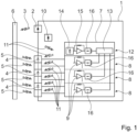
- Fig. 1 shows a block diagram of an exemplary embodiment of a light detection and ranging system 1 according to the present invention.
- the light detection and ranging system 1 comprises a first light source 2 for emitting a light signal to the surroundings of the light detection and ranging system 1.
- the first light source 2 is for example a laser source that emits laser pulses to the surroundings of the light detection and ranging system 1.
- the emitted light signal 3 hits objects 6 in the surroundings of the light detection and ranging system 1 and is reflected or scattered back to the light detection and ranging system 1. These light signals from the surroundings reflected or scattered back to the light detection and ranging system 1 are indicated in Fig. 1 by reference 5.
- the light detection and ranging system 1 further comprises multiple receiving optical sensors 4 for receiving the light signals 5 from the surroundings of the light detection and ranging system 1. These receiving optical sensors 4 are for example photodiodes. The receiving optical sensors 4 are for example arranged in the front part of a vehicle.
- the signals of the multiple receiving optical sensors 4 are processed by an optical receiver system 7 of the light detection and ranging system 1.
- An optical receiver system 7 of the light detection and ranging system 1 of Fig. 1 is shown in Fig. 2 .
- the optical receiver system 7 is preferably implemented in a single integrated circuit.
- the optical receiver system 7 comprises a separate receiver channel 8 for each receiving optical sensor 4.
- the separate receiver channels 8 are separated by dashed lines.
- Each separate receiver channel 8 comprises at least an amplifier 9 for amplifying the signal of the corresponding receiving optical sensor 4.
- the amplifiers 9 have an adjustable gain, to adjust the amplification of the signal of the corresponding receiving optical sensor 4.
- each receiver channel further comprises a signal processing block 16, which for example comprises a buffer, an analog-to-digital converter and/or a signal processing unit.
- the light detection and ranging system 1 further comprises a second light source 10, like a laser source, for emitting a light signal 11 directly to a reference receiver channel 12 of the optical receiver system 7 and the multiple receiving optical sensors 4.
- the reference receiver channel 12 comprises a reference optical sensor 14 and a reference amplifier 15.
- the reference receiver channel 12 also comprises a signal processing block 16 comprising a buffer, an analog-to-digital converter and/or a signal processing unit.
- the optical receiver system 7 further comprises a comparator 13 for comparing the output of the reference receiver channel 12 and the output of each of the separate receiver channels 8.
- the comparator 13 adjusts the gain of the amplifiers 9 of each separate receiver channel 8 based on the result of the comparison of the output of the reference receiver channel 12 and the output of the corresponding separate receiver channel 8.
- the comparator 13 adjusts the gain of the amplifiers of the separate receiver channels 8 in such a way, that the output of each separate receiver channel 8 corresponds to the output of the reference receiver channel 12.
- each separate receiver channel 8 provides the same output to the same light signal 11, i.e. the light signal 11 emitted by the second light source 10.
- the optical receiver system 7 comprises one comparator 13 for comparing the output of the reference receiver channel 12 and the output of each of the separate receiver channels 8. This comparison can be performed serially or at least partially in parallel.
- the comparator 13 is preferably part of the optical receiver system 7 but could also be a separate part of the light detection and ranging system 1.
Landscapes
- Engineering & Computer Science (AREA)
- Computer Networks & Wireless Communication (AREA)
- Physics & Mathematics (AREA)
- General Physics & Mathematics (AREA)
- Radar, Positioning & Navigation (AREA)
- Remote Sensing (AREA)
- Optical Radar Systems And Details Thereof (AREA)
Claims (15)
- Lichterkennungs- und Entfernungsmesssystem (1), das Folgendes umfasst:mindestens eine erste Lichtquelle (2) zum Aussenden eines Lichtsignals (3) in die Umgebung des Lichterkennungs- und Entfernungsmesssystems (1),mehrere optische Empfangssensoren (4) zum Empfangen eines Lichtsignals (5) aus der Umgebung des Lichterkennungs- und -entfernungsmesssystems (1), undein optisches Empfangssystem (7) zum Verarbeiten der Signale der mehreren optischen Empfangssensoren (4), wobei das optische Empfangssystem (7) einen separaten Empfangskanal (8) für jeden optischen Empfangssensor (4) umfasst, wobei jeder separate Empfangskanal (8) einen Verstärker (9) mit einer einstellbaren Verstärkung zum Verstärken des Signals des entsprechenden optischen Empfangssensors (4) umfasst,wobei das Lichtdetektions- und Entfernungsmesssystem (1) ferner eine zweite Lichtquelle (10) umfasst, um ein Lichtsignal (11) direkt an einen Referenzempfangskanal (12) und die mehreren optischen Empfangssensoren (4) auszusenden,wobei das optische Empfangssystem (7) den Referenzempfangskanal (12) und mindestens einen Komparator (13) zum Vergleichen des Ausgangs des Referenzempfangskanals (12) und des Ausgangs jedes der separaten Empfangskanäle (8) umfasst, wobei der Referenzempfangskanal (12) einen optischen Referenzsensor (14) und einen Referenzverstärker (15) umfasst,und wobei der mindestens eine Komparator (13) derart konfiguriert ist, dass er die Verstärkung der Verstärker (9) jedes separaten Empfangskanals (8) auf der Grundlage des Ergebnisses des Vergleichs des Ausgangs des Referenzempfangskanals (12) und des Ausgangs des entsprechenden separaten Empfangskanals (8) einstellt.
- Lichterkennungs- und Entfernungsmesssystem (1) nach Anspruch 1,
wobei die mehreren Empfangskanäle (8) und der Referenzempfangskanal (12) ferner einen Puffer, einen Analog-Digital-Wandler und/oder eine Signalverarbeitungseinheit umfassen. - Lichterkennungs- und Entfernungsmesssystem (1) nach Anspruch 1 oder Anspruch 2,
wobei die mindestens eine erste Lichtquelle (2) und die zweite Lichtquelle (10) von dem Lichterkennungs- und Entfernungsmesssystem (1) gesteuert werden und nicht gleichzeitig Licht aussenden. - Lichterkennungs- und Entfernungsmesssystem (1) nach einem der Ansprüche 1 bis 3,
mit einem separaten Komparator (13) für jeden separaten Empfangskanal (8) zum Vergleichen des Ausgangs des Referenzempfangskanals (12) mit dem Ausgang des entsprechenden Empfangskanals (8). - Lichtdetektions- und Entfernungsmesssystem (1) nach einem der der Ansprüche 1 bis 4,
wobei der Verstärker (9, 15) jedes optischen Empfangskanals (8) und des Referenzempfangskanals (12) ein Transimpedanzverstärker ist. - Lichterkennungs- und Entfernungsmesssystem (1) nach einem der Ansprüche 1 bis 5,
wobei die optischen Empfangssensoren (4, 14) der mehreren optischen Empfangskanäle (8) und des Referenzempfangskanals (12) Photodioden sind und/oder die erste Lichtquelle (2) und/oder die zweite Lichtquelle (10) eine Laserquelle ist. - Lichterkennungs- und Entfernungsmesssystem (1) nach einem der Ansprüche 1 bis 6,
ferner umfassend Sendeoptiken und/oder Empfangsoptiken zum Einstellen der Lichtsendeeigenschaften und/oder der Lichtempfangseigenschaften des Lichterkennungs- und - entfernungsmesssystems (1). - Lichterkennungs- und Entfernungsmesssystem (1) nach einem der Ansprüche 1 bis 7,
wobei das optische Empfangssystem (7) in einer integrierten Schaltung implementiert ist. - Optisches Empfangssystem (7) für ein Lichterkennungs- und Entfernungsmesssystem (1) nach einem der Ansprüche 1 bis 8,
wobeidas optische Empfangssystem (7) den Referenzempfangskanal (12) und mindestens einen Komparator (13) zum Vergleichen des Ausgangs des Referenzempfangskanals (12) und des Ausgangs jedes der separaten Empfangskanäle (8) umfasst, wobei der Referenzempfangskanal (12) einen optischen Referenzsensor (14) und einen Referenzverstärker (15) umfasst,und wobei der mindestens eine Komparator (13) derart konfiguriert ist, dass er die Verstärkung der Verstärker (9) jedes separaten Empfangskanals (8) auf der Grundlage des Ergebnisses des Vergleichs des Ausgangs des Referenzempfangskanals (12) und des Ausgangs des entsprechenden separaten Empfangskanals (8) einstellt. - Verfahren zum Betrieb eines Lichterkennungs- und Entfernungsmesssystems (1), das die folgenden Schritte umfasst:Aussenden eines ersten Lichtsignals (3) in die Umgebung des Lichterkennungs- und Entfernungsmesssystems (1),Empfangen eines Lichtsignals (5) aus der Umgebung des Lichterkennungs- und Entfernungsmesssystems (1) unter Verwendung mehrerer optischer Empfangssensoren (4),Verarbeiten des Signals der optischen Empfangssensoren (4) durch separate Empfangskanäle (8) eines optischen Empfangssystems (7) des Lichterfassungs- und Entfernungsmessungssystems (1), wobei das Verarbeiten zumindest ein Verstärken des Signals der optischen Empfangssensoren (4) durch die separaten Empfangskanäle (8) umfasst,wobei das Verfahren ferner folgenden Schritte umfasst:Aussenden eines zweiten Lichtsignals (11) direkt an einen Referenzempfangskanal (12) und die mehreren optischen Empfangssensoren (4),Vergleichen des Ausgangs des Referenzempfangskanals (12) und des Ausgangs jedes der separaten Empfangskanäle (8),und Einstellen der Verstärkung der Verstärker (9) jedes separaten Empfangskanals (8) auf der Grundlage des Ergebnisses des Vergleichens des Ausgangs des Referenzempfangskanals (12) und des Ausgangs des entsprechenden separaten Empfangskanals (8).
- Verfahren nach Anspruch 10,
wobei das Verarbeiten des Signals der optischen Empfangssensoren (4) ferner ein Puffern des Signals, ein Umwandeln des Signals von einem analogen Bereich in den digitalen Bereich und/oder ein digitales Verarbeiten des Signals umfasst. - Verfahren nach Anspruch 10 oder Anspruch 11,
wobei das erste Lichtsignal (3) und das zweite Lichtsignal (11) nicht gleichzeitig ausgesendet werden. - Verfahren nach einem der Ansprüche 10 bis 12,
wobei das Signal des Referenzempfangskanals (12) und jedes optischen Empfangskanals (8) parallel verglichen werden. - Verfahren nach einem der Ansprüche 10 bis 13,
wobei das Verfahren kontinuierlich während des Betriebs des Lichterkennungs- und Entfernungsmesssystems (1) durchgeführt wird. - Verfahren nach einem der Ansprüche 10 bis 14,
wobei die Schritte Aussenden, Vergleichen und Einstellen in vorbestimmten Intervallen durchgeführt werden.
Priority Applications (3)
| Application Number | Priority Date | Filing Date | Title |
|---|---|---|---|
| EP21200173.9A EP4160264B1 (de) | 2021-09-30 | 2021-09-30 | Lidar-system mit referenz-empfangskanal, geeigneter optischer empfänger und entsprechendes lidar-betriebsverfahren |
| CN202211149138.9A CN115902822A (zh) | 2021-09-30 | 2022-09-20 | 光检测和测距系统及其操作方法、用于光检测和测距系统的光学接收器系统 |
| US17/952,435 US20230098843A1 (en) | 2021-09-30 | 2022-09-26 | Light detection and ranging system, optical receiver system for a light detection and ranging system and method for operating a light detection and ranging system |
Applications Claiming Priority (1)
| Application Number | Priority Date | Filing Date | Title |
|---|---|---|---|
| EP21200173.9A EP4160264B1 (de) | 2021-09-30 | 2021-09-30 | Lidar-system mit referenz-empfangskanal, geeigneter optischer empfänger und entsprechendes lidar-betriebsverfahren |
Publications (2)
| Publication Number | Publication Date |
|---|---|
| EP4160264A1 EP4160264A1 (de) | 2023-04-05 |
| EP4160264B1 true EP4160264B1 (de) | 2025-04-16 |
Family
ID=78134821
Family Applications (1)
| Application Number | Title | Priority Date | Filing Date |
|---|---|---|---|
| EP21200173.9A Active EP4160264B1 (de) | 2021-09-30 | 2021-09-30 | Lidar-system mit referenz-empfangskanal, geeigneter optischer empfänger und entsprechendes lidar-betriebsverfahren |
Country Status (3)
| Country | Link |
|---|---|
| US (1) | US20230098843A1 (de) |
| EP (1) | EP4160264B1 (de) |
| CN (1) | CN115902822A (de) |
Families Citing this family (1)
| Publication number | Priority date | Publication date | Assignee | Title |
|---|---|---|---|---|
| DE102023003375A1 (de) | 2023-08-16 | 2025-02-20 | Michael Dietmar Pierschel | LIDAR System mit erhöhter Ausfallsicherheit |
Family Cites Families (3)
| Publication number | Priority date | Publication date | Assignee | Title |
|---|---|---|---|---|
| DE2452794C3 (de) * | 1974-11-07 | 1979-08-30 | Philips Patentverwaltung Gmbh, 2000 Hamburg | Automatische Pegeleinstellschaltung für voreinstellbare IR-Puls-Überwachungsgeräte mit getaktetem Empfänger |
| CH695516A5 (de) * | 2001-02-05 | 2006-06-15 | Hilti Ag | Verfahren und Vorrichtung zur optoelektronischen Entfernungsmessung. |
| US12085649B2 (en) * | 2020-01-21 | 2024-09-10 | Semiconductor Components Industries, Llc | Imaging systems with single-photon avalanche diodes and ambient light level detection |
-
2021
- 2021-09-30 EP EP21200173.9A patent/EP4160264B1/de active Active
-
2022
- 2022-09-20 CN CN202211149138.9A patent/CN115902822A/zh active Pending
- 2022-09-26 US US17/952,435 patent/US20230098843A1/en active Pending
Also Published As
| Publication number | Publication date |
|---|---|
| CN115902822A (zh) | 2023-04-04 |
| EP4160264A1 (de) | 2023-04-05 |
| US20230098843A1 (en) | 2023-03-30 |
Similar Documents
| Publication | Publication Date | Title |
|---|---|---|
| US11125863B2 (en) | Correction device, correction method, and distance measuring device | |
| US9696425B2 (en) | Optical distance measuring apparatus | |
| CN108344984B (zh) | 光检测和测距系统 | |
| US10852401B2 (en) | Distance measurement apparatus and distance measurement method | |
| US11280888B2 (en) | Low noise frontends for LiDAR receiver and methods for controlling the same comprising a multiplexing circuit for selectively connecting each photodetector to a shared amplifier | |
| US11378687B2 (en) | Distance measurement apparatus and distance measurement method | |
| US10754013B2 (en) | Method and control unit for controlling an emitted light output of a light source of an optical sensor system | |
| US8831908B2 (en) | Signal processing apparatus used for operations for range finding and scanning rangefinder | |
| JPH09199750A (ja) | 複数の視野からの光パルスの検出装置および検出方法 | |
| CN111492261B (zh) | 一种激光接收电路及测距装置、移动平台 | |
| CN114966602A (zh) | 激光雷达噪声去除装置及激光雷达噪声去除方法 | |
| US20230098843A1 (en) | Light detection and ranging system, optical receiver system for a light detection and ranging system and method for operating a light detection and ranging system | |
| JP2016170053A (ja) | レーザレーダ装置 | |
| US8477291B2 (en) | System and method for ranging of targets | |
| EP3640669B1 (de) | Festkörper-treibersystem für optischen empfänger und verfahren zum testen eines festkörper-treibersystems für optischen empfänger | |
| US11782143B2 (en) | Light detection and ranging system and method for operating a light detection and ranging system | |
| KR20020089414A (ko) | 차량의 탑승 공간 내의 물체 또는 사람을 검출하는 장치및 방법 | |
| JP2020076763A5 (de) | ||
| JP3651412B2 (ja) | 距離測定装置および距離測定方法 | |
| EP4036598A1 (de) | Verfahren zum testen eines optischen empfängersystems, insbesondere eines lichtdetektions- und -entfernungsmesssystems | |
| EP3832345A1 (de) | Optisches empfängersystem und verfahren zum betreiben eines optischen empfängersystems, insbesondere eines lichterfassungs- und entfernungsmesssystems | |
| EP3754368A1 (de) | Verstärkersystem und verfahren zum betrieb eines verstärkersystems, insbesondere für ein optisches empfängersystem eines lichtdetektions- und -entfernungsmesssystems | |
| EP3805791A1 (de) | Optisches empfängersystem und verfahren zum betreiben eines optischen empfängersystems, insbesondere eines lichterfassungs- und entfernungsmesssystems |
Legal Events
| Date | Code | Title | Description |
|---|---|---|---|
| PUAI | Public reference made under article 153(3) epc to a published international application that has entered the european phase |
Free format text: ORIGINAL CODE: 0009012 |
|
| STAA | Information on the status of an ep patent application or granted ep patent |
Free format text: STATUS: THE APPLICATION HAS BEEN PUBLISHED |
|
| AK | Designated contracting states |
Kind code of ref document: A1 Designated state(s): AL AT BE BG CH CY CZ DE DK EE ES FI FR GB GR HR HU IE IS IT LI LT LU LV MC MK MT NL NO PL PT RO RS SE SI SK SM TR |
|
| STAA | Information on the status of an ep patent application or granted ep patent |
Free format text: STATUS: REQUEST FOR EXAMINATION WAS MADE |
|
| 17P | Request for examination filed |
Effective date: 20230919 |
|
| RBV | Designated contracting states (corrected) |
Designated state(s): AL AT BE BG CH CY CZ DE DK EE ES FI FR GB GR HR HU IE IS IT LI LT LU LV MC MK MT NL NO PL PT RO RS SE SI SK SM TR |
|
| GRAP | Despatch of communication of intention to grant a patent |
Free format text: ORIGINAL CODE: EPIDOSNIGR1 |
|
| STAA | Information on the status of an ep patent application or granted ep patent |
Free format text: STATUS: GRANT OF PATENT IS INTENDED |
|
| RIC1 | Information provided on ipc code assigned before grant |
Ipc: G01S 7/497 20060101ALI20241021BHEP Ipc: G01S 7/489 20060101AFI20241021BHEP |
|
| INTG | Intention to grant announced |
Effective date: 20241030 |
|
| GRAJ | Information related to disapproval of communication of intention to grant by the applicant or resumption of examination proceedings by the epo deleted |
Free format text: ORIGINAL CODE: EPIDOSDIGR1 |
|
| STAA | Information on the status of an ep patent application or granted ep patent |
Free format text: STATUS: REQUEST FOR EXAMINATION WAS MADE |
|
| GRAP | Despatch of communication of intention to grant a patent |
Free format text: ORIGINAL CODE: EPIDOSNIGR1 |
|
| STAA | Information on the status of an ep patent application or granted ep patent |
Free format text: STATUS: GRANT OF PATENT IS INTENDED |
|
| INTC | Intention to grant announced (deleted) | ||
| GRAS | Grant fee paid |
Free format text: ORIGINAL CODE: EPIDOSNIGR3 |
|
| GRAA | (expected) grant |
Free format text: ORIGINAL CODE: 0009210 |
|
| STAA | Information on the status of an ep patent application or granted ep patent |
Free format text: STATUS: THE PATENT HAS BEEN GRANTED |
|
| INTG | Intention to grant announced |
Effective date: 20250219 |
|
| AK | Designated contracting states |
Kind code of ref document: B1 Designated state(s): AL AT BE BG CH CY CZ DE DK EE ES FI FR GB GR HR HU IE IS IT LI LT LU LV MC MK MT NL NO PL PT RO RS SE SI SK SM TR |
|
| REG | Reference to a national code |
Ref country code: GB Ref legal event code: FG4D |
|
| REG | Reference to a national code |
Ref country code: CH Ref legal event code: EP Ref country code: DE Ref legal event code: R096 Ref document number: 602021029165 Country of ref document: DE |
|
| REG | Reference to a national code |
Ref country code: IE Ref legal event code: FG4D |
|
| REG | Reference to a national code |
Ref country code: NL Ref legal event code: MP Effective date: 20250416 |
|
| PG25 | Lapsed in a contracting state [announced via postgrant information from national office to epo] |
Ref country code: NL Free format text: LAPSE BECAUSE OF FAILURE TO SUBMIT A TRANSLATION OF THE DESCRIPTION OR TO PAY THE FEE WITHIN THE PRESCRIBED TIME-LIMIT Effective date: 20250416 |
|
| REG | Reference to a national code |
Ref country code: AT Ref legal event code: MK05 Ref document number: 1786080 Country of ref document: AT Kind code of ref document: T Effective date: 20250416 |
|
| PG25 | Lapsed in a contracting state [announced via postgrant information from national office to epo] |
Ref country code: PT Free format text: LAPSE BECAUSE OF FAILURE TO SUBMIT A TRANSLATION OF THE DESCRIPTION OR TO PAY THE FEE WITHIN THE PRESCRIBED TIME-LIMIT Effective date: 20250818 Ref country code: ES Free format text: LAPSE BECAUSE OF FAILURE TO SUBMIT A TRANSLATION OF THE DESCRIPTION OR TO PAY THE FEE WITHIN THE PRESCRIBED TIME-LIMIT Effective date: 20250416 Ref country code: FI Free format text: LAPSE BECAUSE OF FAILURE TO SUBMIT A TRANSLATION OF THE DESCRIPTION OR TO PAY THE FEE WITHIN THE PRESCRIBED TIME-LIMIT Effective date: 20250416 |
|
| PGFP | Annual fee paid to national office [announced via postgrant information from national office to epo] |
Ref country code: DE Payment date: 20250926 Year of fee payment: 5 |
|
| REG | Reference to a national code |
Ref country code: LT Ref legal event code: MG9D |
|
| PG25 | Lapsed in a contracting state [announced via postgrant information from national office to epo] |
Ref country code: NO Free format text: LAPSE BECAUSE OF FAILURE TO SUBMIT A TRANSLATION OF THE DESCRIPTION OR TO PAY THE FEE WITHIN THE PRESCRIBED TIME-LIMIT Effective date: 20250716 Ref country code: GR Free format text: LAPSE BECAUSE OF FAILURE TO SUBMIT A TRANSLATION OF THE DESCRIPTION OR TO PAY THE FEE WITHIN THE PRESCRIBED TIME-LIMIT Effective date: 20250717 |
|
| PG25 | Lapsed in a contracting state [announced via postgrant information from national office to epo] |
Ref country code: PL Free format text: LAPSE BECAUSE OF FAILURE TO SUBMIT A TRANSLATION OF THE DESCRIPTION OR TO PAY THE FEE WITHIN THE PRESCRIBED TIME-LIMIT Effective date: 20250416 |
|
| PG25 | Lapsed in a contracting state [announced via postgrant information from national office to epo] |
Ref country code: BG Free format text: LAPSE BECAUSE OF FAILURE TO SUBMIT A TRANSLATION OF THE DESCRIPTION OR TO PAY THE FEE WITHIN THE PRESCRIBED TIME-LIMIT Effective date: 20250416 |
|
| PG25 | Lapsed in a contracting state [announced via postgrant information from national office to epo] |
Ref country code: HR Free format text: LAPSE BECAUSE OF FAILURE TO SUBMIT A TRANSLATION OF THE DESCRIPTION OR TO PAY THE FEE WITHIN THE PRESCRIBED TIME-LIMIT Effective date: 20250416 |
|
| PG25 | Lapsed in a contracting state [announced via postgrant information from national office to epo] |
Ref country code: AT Free format text: LAPSE BECAUSE OF FAILURE TO SUBMIT A TRANSLATION OF THE DESCRIPTION OR TO PAY THE FEE WITHIN THE PRESCRIBED TIME-LIMIT Effective date: 20250416 |
|
| PG25 | Lapsed in a contracting state [announced via postgrant information from national office to epo] |
Ref country code: RS Free format text: LAPSE BECAUSE OF FAILURE TO SUBMIT A TRANSLATION OF THE DESCRIPTION OR TO PAY THE FEE WITHIN THE PRESCRIBED TIME-LIMIT Effective date: 20250716 |
|
| PG25 | Lapsed in a contracting state [announced via postgrant information from national office to epo] |
Ref country code: IS Free format text: LAPSE BECAUSE OF FAILURE TO SUBMIT A TRANSLATION OF THE DESCRIPTION OR TO PAY THE FEE WITHIN THE PRESCRIBED TIME-LIMIT Effective date: 20250816 |
|
| PG25 | Lapsed in a contracting state [announced via postgrant information from national office to epo] |
Ref country code: LV Free format text: LAPSE BECAUSE OF FAILURE TO SUBMIT A TRANSLATION OF THE DESCRIPTION OR TO PAY THE FEE WITHIN THE PRESCRIBED TIME-LIMIT Effective date: 20250416 |
|
| PG25 | Lapsed in a contracting state [announced via postgrant information from national office to epo] |
Ref country code: DK Free format text: LAPSE BECAUSE OF FAILURE TO SUBMIT A TRANSLATION OF THE DESCRIPTION OR TO PAY THE FEE WITHIN THE PRESCRIBED TIME-LIMIT Effective date: 20250416 Ref country code: SM Free format text: LAPSE BECAUSE OF FAILURE TO SUBMIT A TRANSLATION OF THE DESCRIPTION OR TO PAY THE FEE WITHIN THE PRESCRIBED TIME-LIMIT Effective date: 20250416 |
|
| REG | Reference to a national code |
Ref country code: DE Ref legal event code: R097 Ref document number: 602021029165 Country of ref document: DE |
|
| PG25 | Lapsed in a contracting state [announced via postgrant information from national office to epo] |
Ref country code: CZ Free format text: LAPSE BECAUSE OF FAILURE TO SUBMIT A TRANSLATION OF THE DESCRIPTION OR TO PAY THE FEE WITHIN THE PRESCRIBED TIME-LIMIT Effective date: 20250416 |
|
| PG25 | Lapsed in a contracting state [announced via postgrant information from national office to epo] |
Ref country code: EE Free format text: LAPSE BECAUSE OF FAILURE TO SUBMIT A TRANSLATION OF THE DESCRIPTION OR TO PAY THE FEE WITHIN THE PRESCRIBED TIME-LIMIT Effective date: 20250416 |
|
| PG25 | Lapsed in a contracting state [announced via postgrant information from national office to epo] |
Ref country code: SK Free format text: LAPSE BECAUSE OF FAILURE TO SUBMIT A TRANSLATION OF THE DESCRIPTION OR TO PAY THE FEE WITHIN THE PRESCRIBED TIME-LIMIT Effective date: 20250416 |
|
| PG25 | Lapsed in a contracting state [announced via postgrant information from national office to epo] |
Ref country code: IT Free format text: LAPSE BECAUSE OF FAILURE TO SUBMIT A TRANSLATION OF THE DESCRIPTION OR TO PAY THE FEE WITHIN THE PRESCRIBED TIME-LIMIT Effective date: 20250416 |
|
| PG25 | Lapsed in a contracting state [announced via postgrant information from national office to epo] |
Ref country code: RO Free format text: LAPSE BECAUSE OF FAILURE TO SUBMIT A TRANSLATION OF THE DESCRIPTION OR TO PAY THE FEE WITHIN THE PRESCRIBED TIME-LIMIT Effective date: 20250416 |
|
| PLBE | No opposition filed within time limit |
Free format text: ORIGINAL CODE: 0009261 |
|
| STAA | Information on the status of an ep patent application or granted ep patent |
Free format text: STATUS: NO OPPOSITION FILED WITHIN TIME LIMIT |
|
| REG | Reference to a national code |
Ref country code: CH Ref legal event code: L10 Free format text: ST27 STATUS EVENT CODE: U-0-0-L10-L00 (AS PROVIDED BY THE NATIONAL OFFICE) Effective date: 20260225 |
|
| 26N | No opposition filed |
Effective date: 20260119 |
|
| REG | Reference to a national code |
Ref country code: CH Ref legal event code: H13 Free format text: ST27 STATUS EVENT CODE: U-0-0-H10-H13 (AS PROVIDED BY THE NATIONAL OFFICE) Effective date: 20260425 |