EP4160249A1 - System for detecting, localizing and sharing potholes - Google Patents
System for detecting, localizing and sharing potholes Download PDFInfo
- Publication number
- EP4160249A1 EP4160249A1 EP21200174.7A EP21200174A EP4160249A1 EP 4160249 A1 EP4160249 A1 EP 4160249A1 EP 21200174 A EP21200174 A EP 21200174A EP 4160249 A1 EP4160249 A1 EP 4160249A1
- Authority
- EP
- European Patent Office
- Prior art keywords
- potholes
- vehicle
- confirmed
- road
- cartography
- Prior art date
- Legal status (The legal status is an assumption and is not a legal conclusion. Google has not performed a legal analysis and makes no representation as to the accuracy of the status listed.)
- Pending
Links
- 238000000034 method Methods 0.000 claims abstract description 37
- 238000012545 processing Methods 0.000 claims abstract description 6
- 230000004807 localization Effects 0.000 claims abstract description 5
- 239000003086 colorant Substances 0.000 claims description 4
- 238000004891 communication Methods 0.000 claims description 3
- 230000001955 cumulated effect Effects 0.000 claims description 3
- 238000003384 imaging method Methods 0.000 claims description 3
- 238000002592 echocardiography Methods 0.000 description 9
- 238000001514 detection method Methods 0.000 description 7
- 230000008901 benefit Effects 0.000 description 5
- 230000006870 function Effects 0.000 description 5
- 230000008569 process Effects 0.000 description 5
- 230000000295 complement effect Effects 0.000 description 4
- 230000033001 locomotion Effects 0.000 description 4
- 230000006399 behavior Effects 0.000 description 3
- 230000010267 cellular communication Effects 0.000 description 3
- 238000005065 mining Methods 0.000 description 3
- 239000000725 suspension Substances 0.000 description 3
- XLYOFNOQVPJJNP-UHFFFAOYSA-N water Substances O XLYOFNOQVPJJNP-UHFFFAOYSA-N 0.000 description 3
- 238000010586 diagram Methods 0.000 description 2
- 230000001771 impaired effect Effects 0.000 description 2
- 230000010354 integration Effects 0.000 description 2
- 238000005259 measurement Methods 0.000 description 2
- 241000791900 Selene vomer Species 0.000 description 1
- 239000006096 absorbing agent Substances 0.000 description 1
- 230000001133 acceleration Effects 0.000 description 1
- 230000002411 adverse Effects 0.000 description 1
- 238000013528 artificial neural network Methods 0.000 description 1
- 230000009286 beneficial effect Effects 0.000 description 1
- 238000004364 calculation method Methods 0.000 description 1
- 238000012937 correction Methods 0.000 description 1
- 230000001627 detrimental effect Effects 0.000 description 1
- 238000005562 fading Methods 0.000 description 1
- 238000001914 filtration Methods 0.000 description 1
- 238000013507 mapping Methods 0.000 description 1
- 239000000463 material Substances 0.000 description 1
- 230000007246 mechanism Effects 0.000 description 1
- 230000010355 oscillation Effects 0.000 description 1
- 230000008447 perception Effects 0.000 description 1
- 230000008439 repair process Effects 0.000 description 1
- 230000004044 response Effects 0.000 description 1
- 230000035939 shock Effects 0.000 description 1
- 230000006641 stabilisation Effects 0.000 description 1
- 238000011105 stabilization Methods 0.000 description 1
- 230000003068 static effect Effects 0.000 description 1
- 239000011800 void material Substances 0.000 description 1
Images


Classifications
-
- G—PHYSICS
- G01—MEASURING; TESTING
- G01S—RADIO DIRECTION-FINDING; RADIO NAVIGATION; DETERMINING DISTANCE OR VELOCITY BY USE OF RADIO WAVES; LOCATING OR PRESENCE-DETECTING BY USE OF THE REFLECTION OR RERADIATION OF RADIO WAVES; ANALOGOUS ARRANGEMENTS USING OTHER WAVES
- G01S7/00—Details of systems according to groups G01S13/00, G01S15/00, G01S17/00
- G01S7/003—Transmission of data between radar, sonar or lidar systems and remote stations
-
- B—PERFORMING OPERATIONS; TRANSPORTING
- B60—VEHICLES IN GENERAL
- B60W—CONJOINT CONTROL OF VEHICLE SUB-UNITS OF DIFFERENT TYPE OR DIFFERENT FUNCTION; CONTROL SYSTEMS SPECIALLY ADAPTED FOR HYBRID VEHICLES; ROAD VEHICLE DRIVE CONTROL SYSTEMS FOR PURPOSES NOT RELATED TO THE CONTROL OF A PARTICULAR SUB-UNIT
- B60W50/00—Details of control systems for road vehicle drive control not related to the control of a particular sub-unit, e.g. process diagnostic or vehicle driver interfaces
- B60W50/08—Interaction between the driver and the control system
- B60W50/14—Means for informing the driver, warning the driver or prompting a driver intervention
-
- B—PERFORMING OPERATIONS; TRANSPORTING
- B60—VEHICLES IN GENERAL
- B60W—CONJOINT CONTROL OF VEHICLE SUB-UNITS OF DIFFERENT TYPE OR DIFFERENT FUNCTION; CONTROL SYSTEMS SPECIALLY ADAPTED FOR HYBRID VEHICLES; ROAD VEHICLE DRIVE CONTROL SYSTEMS FOR PURPOSES NOT RELATED TO THE CONTROL OF A PARTICULAR SUB-UNIT
- B60W40/00—Estimation or calculation of non-directly measurable driving parameters for road vehicle drive control systems not related to the control of a particular sub unit, e.g. by using mathematical models
- B60W40/02—Estimation or calculation of non-directly measurable driving parameters for road vehicle drive control systems not related to the control of a particular sub unit, e.g. by using mathematical models related to ambient conditions
- B60W40/06—Road conditions
-
- G—PHYSICS
- G01—MEASURING; TESTING
- G01C—MEASURING DISTANCES, LEVELS OR BEARINGS; SURVEYING; NAVIGATION; GYROSCOPIC INSTRUMENTS; PHOTOGRAMMETRY OR VIDEOGRAMMETRY
- G01C21/00—Navigation; Navigational instruments not provided for in groups G01C1/00 - G01C19/00
- G01C21/26—Navigation; Navigational instruments not provided for in groups G01C1/00 - G01C19/00 specially adapted for navigation in a road network
- G01C21/34—Route searching; Route guidance
- G01C21/3453—Special cost functions, i.e. other than distance or default speed limit of road segments
- G01C21/3461—Preferred or disfavoured areas, e.g. dangerous zones, toll or emission zones, intersections, manoeuvre types, segments such as motorways, toll roads, ferries
-
- G—PHYSICS
- G01—MEASURING; TESTING
- G01C—MEASURING DISTANCES, LEVELS OR BEARINGS; SURVEYING; NAVIGATION; GYROSCOPIC INSTRUMENTS; PHOTOGRAMMETRY OR VIDEOGRAMMETRY
- G01C21/00—Navigation; Navigational instruments not provided for in groups G01C1/00 - G01C19/00
- G01C21/26—Navigation; Navigational instruments not provided for in groups G01C1/00 - G01C19/00 specially adapted for navigation in a road network
- G01C21/34—Route searching; Route guidance
- G01C21/36—Input/output arrangements for on-board computers
- G01C21/3667—Display of a road map
-
- G—PHYSICS
- G01—MEASURING; TESTING
- G01C—MEASURING DISTANCES, LEVELS OR BEARINGS; SURVEYING; NAVIGATION; GYROSCOPIC INSTRUMENTS; PHOTOGRAMMETRY OR VIDEOGRAMMETRY
- G01C21/00—Navigation; Navigational instruments not provided for in groups G01C1/00 - G01C19/00
- G01C21/38—Electronic maps specially adapted for navigation; Updating thereof
- G01C21/3804—Creation or updating of map data
- G01C21/3807—Creation or updating of map data characterised by the type of data
- G01C21/3815—Road data
- G01C21/3822—Road feature data, e.g. slope data
-
- G—PHYSICS
- G01—MEASURING; TESTING
- G01S—RADIO DIRECTION-FINDING; RADIO NAVIGATION; DETERMINING DISTANCE OR VELOCITY BY USE OF RADIO WAVES; LOCATING OR PRESENCE-DETECTING BY USE OF THE REFLECTION OR RERADIATION OF RADIO WAVES; ANALOGOUS ARRANGEMENTS USING OTHER WAVES
- G01S13/00—Systems using the reflection or reradiation of radio waves, e.g. radar systems; Analogous systems using reflection or reradiation of waves whose nature or wavelength is irrelevant or unspecified
- G01S13/02—Systems using reflection of radio waves, e.g. primary radar systems; Analogous systems
- G01S13/06—Systems determining position data of a target
- G01S13/42—Simultaneous measurement of distance and other co-ordinates
- G01S13/426—Scanning radar, e.g. 3D radar
-
- G—PHYSICS
- G01—MEASURING; TESTING
- G01S—RADIO DIRECTION-FINDING; RADIO NAVIGATION; DETERMINING DISTANCE OR VELOCITY BY USE OF RADIO WAVES; LOCATING OR PRESENCE-DETECTING BY USE OF THE REFLECTION OR RERADIATION OF RADIO WAVES; ANALOGOUS ARRANGEMENTS USING OTHER WAVES
- G01S13/00—Systems using the reflection or reradiation of radio waves, e.g. radar systems; Analogous systems using reflection or reradiation of waves whose nature or wavelength is irrelevant or unspecified
- G01S13/86—Combinations of radar systems with non-radar systems, e.g. sonar, direction finder
- G01S13/865—Combination of radar systems with lidar systems
-
- G—PHYSICS
- G01—MEASURING; TESTING
- G01S—RADIO DIRECTION-FINDING; RADIO NAVIGATION; DETERMINING DISTANCE OR VELOCITY BY USE OF RADIO WAVES; LOCATING OR PRESENCE-DETECTING BY USE OF THE REFLECTION OR RERADIATION OF RADIO WAVES; ANALOGOUS ARRANGEMENTS USING OTHER WAVES
- G01S13/00—Systems using the reflection or reradiation of radio waves, e.g. radar systems; Analogous systems using reflection or reradiation of waves whose nature or wavelength is irrelevant or unspecified
- G01S13/88—Radar or analogous systems specially adapted for specific applications
- G01S13/89—Radar or analogous systems specially adapted for specific applications for mapping or imaging
- G01S13/90—Radar or analogous systems specially adapted for specific applications for mapping or imaging using synthetic aperture techniques, e.g. synthetic aperture radar [SAR] techniques
- G01S13/904—SAR modes
- G01S13/9043—Forward-looking SAR
-
- G—PHYSICS
- G01—MEASURING; TESTING
- G01S—RADIO DIRECTION-FINDING; RADIO NAVIGATION; DETERMINING DISTANCE OR VELOCITY BY USE OF RADIO WAVES; LOCATING OR PRESENCE-DETECTING BY USE OF THE REFLECTION OR RERADIATION OF RADIO WAVES; ANALOGOUS ARRANGEMENTS USING OTHER WAVES
- G01S13/00—Systems using the reflection or reradiation of radio waves, e.g. radar systems; Analogous systems using reflection or reradiation of waves whose nature or wavelength is irrelevant or unspecified
- G01S13/88—Radar or analogous systems specially adapted for specific applications
- G01S13/93—Radar or analogous systems specially adapted for specific applications for anti-collision purposes
- G01S13/931—Radar or analogous systems specially adapted for specific applications for anti-collision purposes of land vehicles
-
- G—PHYSICS
- G01—MEASURING; TESTING
- G01S—RADIO DIRECTION-FINDING; RADIO NAVIGATION; DETERMINING DISTANCE OR VELOCITY BY USE OF RADIO WAVES; LOCATING OR PRESENCE-DETECTING BY USE OF THE REFLECTION OR RERADIATION OF RADIO WAVES; ANALOGOUS ARRANGEMENTS USING OTHER WAVES
- G01S7/00—Details of systems according to groups G01S13/00, G01S15/00, G01S17/00
- G01S7/02—Details of systems according to groups G01S13/00, G01S15/00, G01S17/00 of systems according to group G01S13/00
- G01S7/28—Details of pulse systems
- G01S7/285—Receivers
- G01S7/292—Extracting wanted echo-signals
-
- B—PERFORMING OPERATIONS; TRANSPORTING
- B60—VEHICLES IN GENERAL
- B60W—CONJOINT CONTROL OF VEHICLE SUB-UNITS OF DIFFERENT TYPE OR DIFFERENT FUNCTION; CONTROL SYSTEMS SPECIALLY ADAPTED FOR HYBRID VEHICLES; ROAD VEHICLE DRIVE CONTROL SYSTEMS FOR PURPOSES NOT RELATED TO THE CONTROL OF A PARTICULAR SUB-UNIT
- B60W50/00—Details of control systems for road vehicle drive control not related to the control of a particular sub-unit, e.g. process diagnostic or vehicle driver interfaces
- B60W50/08—Interaction between the driver and the control system
- B60W50/14—Means for informing the driver, warning the driver or prompting a driver intervention
- B60W2050/146—Display means
-
- B60W2420/408—
-
- B—PERFORMING OPERATIONS; TRANSPORTING
- B60—VEHICLES IN GENERAL
- B60W—CONJOINT CONTROL OF VEHICLE SUB-UNITS OF DIFFERENT TYPE OR DIFFERENT FUNCTION; CONTROL SYSTEMS SPECIALLY ADAPTED FOR HYBRID VEHICLES; ROAD VEHICLE DRIVE CONTROL SYSTEMS FOR PURPOSES NOT RELATED TO THE CONTROL OF A PARTICULAR SUB-UNIT
- B60W2552/00—Input parameters relating to infrastructure
- B60W2552/35—Road bumpiness, e.g. pavement or potholes
-
- B—PERFORMING OPERATIONS; TRANSPORTING
- B60—VEHICLES IN GENERAL
- B60W—CONJOINT CONTROL OF VEHICLE SUB-UNITS OF DIFFERENT TYPE OR DIFFERENT FUNCTION; CONTROL SYSTEMS SPECIALLY ADAPTED FOR HYBRID VEHICLES; ROAD VEHICLE DRIVE CONTROL SYSTEMS FOR PURPOSES NOT RELATED TO THE CONTROL OF A PARTICULAR SUB-UNIT
- B60W2556/00—Input parameters relating to data
- B60W2556/45—External transmission of data to or from the vehicle
-
- G—PHYSICS
- G01—MEASURING; TESTING
- G01S—RADIO DIRECTION-FINDING; RADIO NAVIGATION; DETERMINING DISTANCE OR VELOCITY BY USE OF RADIO WAVES; LOCATING OR PRESENCE-DETECTING BY USE OF THE REFLECTION OR RERADIATION OF RADIO WAVES; ANALOGOUS ARRANGEMENTS USING OTHER WAVES
- G01S13/00—Systems using the reflection or reradiation of radio waves, e.g. radar systems; Analogous systems using reflection or reradiation of waves whose nature or wavelength is irrelevant or unspecified
- G01S13/88—Radar or analogous systems specially adapted for specific applications
- G01S13/93—Radar or analogous systems specially adapted for specific applications for anti-collision purposes
- G01S13/931—Radar or analogous systems specially adapted for specific applications for anti-collision purposes of land vehicles
- G01S2013/9316—Radar or analogous systems specially adapted for specific applications for anti-collision purposes of land vehicles combined with communication equipment with other vehicles or with base stations
-
- G—PHYSICS
- G01—MEASURING; TESTING
- G01S—RADIO DIRECTION-FINDING; RADIO NAVIGATION; DETERMINING DISTANCE OR VELOCITY BY USE OF RADIO WAVES; LOCATING OR PRESENCE-DETECTING BY USE OF THE REFLECTION OR RERADIATION OF RADIO WAVES; ANALOGOUS ARRANGEMENTS USING OTHER WAVES
- G01S13/00—Systems using the reflection or reradiation of radio waves, e.g. radar systems; Analogous systems using reflection or reradiation of waves whose nature or wavelength is irrelevant or unspecified
- G01S13/88—Radar or analogous systems specially adapted for specific applications
- G01S13/93—Radar or analogous systems specially adapted for specific applications for anti-collision purposes
- G01S13/931—Radar or analogous systems specially adapted for specific applications for anti-collision purposes of land vehicles
- G01S2013/9327—Sensor installation details
- G01S2013/93271—Sensor installation details in the front of the vehicles
Definitions
- Quality of road surface and structure is a key factor with regard to road transport efficiency and safety. Also quality of track surface and structure is a key factor with regard to off-road transport efficiency, like in the mining industry, or within other private or semi-private premises.
- a method for at least detecting, localizing, and reporting (showing/displaying) potholes (9) on a road where the method is being carried out in a system comprising a sensing device (4) mounted on a vehicle (V), a cartography display mounted on the vehicle, and an onboard control unit (6) aboard the vehicle, the sensing device comprising at least a radar device, the method comprising:
- pothole should be construed broadly, namely there is no limitation about the size and conformation of potholes, it can be a continuous area of uneven and damaged road portion.
- reporting potholes is to be understood as reporting potholes information to a truck driver. This can be done in a graphical manner, in such case reporting means showing and/or displaying reporting potholes on a navigation map. It is not excluded though to do such a report by audio guidance, instead or in addition to the graphical display.
- the radar device may be preferably a SAR-type radar, namely synthetic aperture radar device.
- SAR-type radar takes advantages of phase detection. Detection is improved from vehicle motion, same point is gradually illuminated from different directions, which improves the perception even with a small surface antenna.
- first candidates potholes are extracted from the data flow, and a likelihood of a confirmed pothole is assessed with subsequent radar scans, and such pothole thereby confirmed being selected as a first confirmed pothole.
- tracking first candidate potholes following vehicle motion like with SLAM/ICP algorithm helps determining and confirming a real pothole, it also helps discarding an object lying on the road like a leaf or leaves.
- SLAM stands for Simultaneous localization and mapping
- ICP is exemplifier later in the application.
- a first candidate pothole is determined as a local recess in the road surface, namely a local recess with regard to a higher neighboring border.
- the proposed method may comprise: b3- characterizing each of the first confirmed potholes by a set of size characteristics, comprising at least one of : its depth (9D), its width (9W), its length (9L).
- the proposed method may comprise:
- Ranking of first confirmed potholes provides is beneficial, it denotes hierarchy about danger level of all potholes.
- the proposed method may comprise:
- the proposed method may comprise:
- Truck drivers can take advantage of other users knowledge about potholes, to choose the more relevant path and to know well in advance the possible danger(s) created by pothole.
- the proposed method may comprise: d2- displaying, on the cartography display, second potholes.
- the displayed map can show potholes ahead, beyond the range of the onboard radar device.
- the present disclosure is also directed to a system configured to carry out the method exposed above.
- the promoted system displays on the one hand potholes directly determined in real-time fashion via the onboard sensing device (so-called 'first' potholes), and on the other hand, known potholes determined beforehand by the concerned vehicle or by other vehicles (so-called 'second' potholes).
- the second potholes are retrieved from a local database, and if a wireless or cellular communication is available, the second potholes are retrieved from a remote database.
- the proposed method may comprise: d3 - displaying, on the cartography display, with various icons and/or colors, each of the first and second potholes together with their respective severity rating.
- the sensing device comprises, besides the radar device, a lidar device and/or a ToF camera, ToF camera standing for Time Of Flight camera.
- the proposed method may comprise: b10- identifying in the data flow generally damaged/uneven portions on the road surface.
- the area of interest encompasses the whole width of the road/track.
- the proposed method may comprise: d2- displaying, on the cartography display, one or more itinerary to go from a departure location (A) to a destination location (B), each of the one or more itinerary being displayed together with a respective cumulated pothole severity rating.
- this allows the truck driver to decide which itinerary is best for the travel to carry out.
- the present disclosure is also directed to a system an imaging device mounted on a vehicle, a cartography display mounted on the vehicle, and an onboard control unit aboard the vehicle, configured to carry out the method as exposed above.
- the system may further comprise a remote server and a data link allowing data exchange between the remote server and the onboard control unit.
- the sensing device comprises, besides the radar device, an inertial measurement unit (IMU).
- IMU inertial measurement unit
- the IMU data can be used to provide a warning message to an upcoming truck in same path.
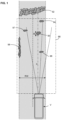
- Figure 1 shows diagrammatically a top view of a road where one vehicle V is moving.
- the present disclosure relates to dealing with poor road surface quality. Also of particular interest here are structurally damaged portions of road infrastructure at the center or at the borders of the road.
- potholes there are shown various examples of potholes in figure 1 .
- potholes are generically denoted by reference 9 .
- Potholes can be located in road lane that is to be travelled by the vehicle. Potholes can also be located in another road lane, where vehicle(s) travel in the same direction, or where vehicles can travel in opposite direction.
- the general longitudinal motion direction of the vehicle V is denoted X .
- axis X is generally not horizontal.
- the inclination of the road can result in a longitudinal axis oriented upwards or downwards.
- the orientation of longitudinal axis is not necessarily parallel to the road surface, there are swing oscillations (pitch and roll).
- the vehicle can exhibit a pitch-up posture or a pitch-down posture, notably according to carried payload.
- truck of all types including off-road transport.
- the truck considered here can be the traction unit in a tractor/trailer configuration or it can be a utility 'carrier' truck.
- off road trucks like the ones used in the mining industry. We consider here not only vehicles/truck circulating on public roads but also vehicles/truck circulating elsewhere like in private premises or semi-private premises. We consider here vehicles/truck used in mining resorts.
- the term 'road' is to be construed broadly including track, paths or the like.
- the borders of such track/road may be clearly identified in some cases, but also in other cases the borders cannot be clearly identified.
- the lateral shoulders may be of any structure.
- an area of interest 66 Said area of interest 66 is located in front of and ahead the vehicle of interest.
- the area of interest 66 includes at least a surface of a road to be traveled by the vehicle.
- the area of interest is 3D, i.e. a volume of interest.
- the area of interest encompasses the whole width RW of the road (see figure 1 ).
- the height of the volume of interest is slightly greater than a height H1 where the sensing device (to be discussed later) is arranged on the vehicle.
- H1 is taken with the ground as reference as shown at figure 2 .
- the area of interest encompasses the road surface and beneath. More details will be discussed later about the area of interest 66 .
- VSP The forward velocity of the vehicle denoted VSP .
- the vehicle V comprises a geolocation system receiver, configured to receive signals from satellites 75 and to deliver therefrom a plurality of successive geolocations GPS(i), the index i denotes the rank in the series of successive geolocations.
- Vehicle speed VSP can be obtained from the wheel speed of the wheels or from the derivative of the successive geolocations GPS(i), or both.
- Geolocations systems of this type are known per se, such as GPS, Galileo, Glonass or the like, and therefore not described in detail herein.
- RTK GPS or differential GPS.
- the electronic control unit 6 (to be discussed later) can determine from geolocation signals the current geolocation of the vehicle.
- cartography there may be provided a local cartography map, as known per se. Further regarding cartography, there may be provided a remote cartography map, downloaded upon request and desired geolocations as also known per se. Hybrid configurations are also considered, where basic map can be present in a local cartography map, whereas complementary maps and/or traffic real-time information are downloaded on need from one or more remote servers.
- cartography information can comprise the type of each road or track segment (width, number of lane(s) one/two ways, flat/uphill/downhill, material of pavement, type of shoulder, ...)
- the map is displayed on a cartography display 7 provided for the vehicle driver.
- a dead reckoning function can be provided. Integration of speed and steering angle is one possible solution.
- the inertial Measurement Unit can provide precise localization of the vehicle on the road, and position of potholes can be displayed to the truck driver with a good accuracy.
- the sensing device 4 is preferably installed at the uppermost possible position looking ahead, for example shown in the figures 2 and 3 , at the top of the front face of the cabin.
- H1 denoted the height position of the sensing device with regard to the ground reference.
- H1 is typically comprised between 200 cm and 300 cm, preferably comprised between 220 cm and 260 cm. It should be noted that a sensing device at this height H1 is not prone to splashing. By contrast, in other known systems, sensors located under the vehicle chassis or at the shock absorbers are bound to be dirtied quickly by splashing of mud.
- the promoted system here is deprived of sensor(s) below a 1 meter threshold from the ground level.
- the sensing device comprises at least a radar device, i.e. a radar-type scanner, simply 'radar' in short.
- the radar 51 uses bursts of electromagnetic waves Tx and echoes Rx coming back from objects present in the scene.
- time difference ⁇ T between transmitting burst instant and backscatter echo reception is proportional to the distance separating the radar from the surface of an object were the electromagnetic waves have bounced back.
- radar device operation is not impaired by darkness, and is not impaired by light rain of light fog.
- the amplitude Amp and phase of each echo is recorded.
- the amplitude and phase of the echoes Rx depend on the nature of the object that backscatters the impinging electromagnetic waves Tx . It is understood that a pothole creates an echo different from an even road surface. Also a pothole filled with water or mud creates a further different echo from an even road surface or a void pothole.
- the electromagnetic waves used for radar unit 51 have a carrier frequency comprised between 10 MHz and 100 GHz.
- the radar unit 51 is a 77 GHz radar scanner.
- the radar unit is a 24 GHz radar scanner.
- the radar unit 51 exhibits a first field of view expressed in an angular scan sector ( ⁇ azi, cpelev). This field of view encompasses the above mentioned area of interest 66 .
- Angle ⁇ denotes azimuthal sweep, whereas angle ⁇ denotes vertical sweep.
- the frequency of scan repetition is comprised between 20 Hz and 60 Hz, i.e. each point of the field of view is scanned 20 to 60 times per second.
- X1 denote the longitudinal axis of the vehicle at the level of the sensing device.
- Angle ⁇ is the vertical deviation versus X1 .
- Angle ⁇ ' denotes the angle of the burst ray 40 versus the ground.
- the angular scan domain can be trapezoidal.
- azimuthal sweep ⁇ is comprised between - ⁇ 2 and ⁇ 2 when angle ⁇ corresponds to a max look down attitude.
- angle ⁇ scan sector is 85° as shown at figures 3 and 6 .
- limit angle ⁇ 1 is comprised between 10° and 15°
- limit angle ⁇ 2 is comprised between 20° and 45°.
- the angular scan domain is symmetrical with regard to the longitudinal axis (left/right symmetry).
- the angular scan domain can be enlarged on the side of the steering direction, i.e. this means enlarging the area of interest on the turning side.
- the angular scan domain can be enlarged or biased according the itinerary to be followed.
- the area of interest can be defined in accordance with the geolocation map (cartography and current position), the area of interest matches with the road curvature ahead.
- the radar device is a SAR Radar.
- potholes retrieved during the above process by the sensing device are called 'first' by contrast with other potholes recorded previously or known from other source device are called 'second'.
- the data flow further processing can be performed through digital filters, fast Fourier transform, neural network, etc...
- the radar device can be mounted on a stabilization platform with a mechanical low pass filtering that discards all the undesirable vibrations.
- data obtained from a new radar scan can be 'registered' to the previous one, in other words the scan is realigned with the help of a landmark or with the help of an ICP algorithm (ICP : Iterative Closest Point).
- the system comprises the onboard control unit 6 cartography display 7, the radar device 51, a memory or database 8 , which can be integrated or not in the onboard control unit 6. Further, the system comprises a wireless/cellular communication means 68 . Thanks to the wireless/cellular communication means 68 , the control unit 6 is internet enabled and can access a remote or database 80 .
- the system may comprise the lidar device 52 .
- the system may comprise one 3D camera or time-of-flight camera (ToF camera).
- the system may comprise two cameras 53,54 for stereoscopic vision.
- Lidar and camera(s) can be located at the top of the cabin, but not necessarily at the same location of the radar device.
- the radar device 51 may be located on the median vertical plane.
- Data gathered by the lidar or the camera(s) can be used to complement data gathered by the radar device.
- Candidate potholes can correspond to predetermined echoes, or series of echoes of the same impinged area with successive radar scans. Predetermined echoes can be stored in lookup tables, reference tables or the like. There also may be provided a learning mechanism.
- Each of the potholes can be characterized by a set of size characteristics, comprising at least one of : its depth 9D , its width 9W , its length 9L . (See figures 1 and 9 ).
- a pothole rating according to severity with regard to safety and/or potential damage to vehicle. This consists in allocating a severity rating SR to each of the potholes (notably the first confirmed potholes).
- Severity rating can be defined with the help of a severity scale ranging from 1 to 10. According to one example, a shallow recess will be rated 1, a substantial pothole would be rated 5 and a deep pothole would be rated 10.
- the severity rating is possibly calculated as a function of its depth 9D .
- a severity rating can also be allocated to a large damaged area, i.e. an area wider than a single individual pothole.
- the proposed method includes sharing pothole information with other parties. This means making available first confirmed potholes and associated geolocation, preferably with its size characteristics, to a third party.
- a third party can be a remote server 3 .
- Such third party can be one or more neighboring vehicle(s) via Car2Car communication.
- an uplink 18 enabling vehicles equipped with the radar device to transmit data to a remote server 3.
- vehicles V61 and V62 transmit their information through uplink 18 to the remote server 3 (or as illustrated at figure 4 generally to one or more unit(s) in the cloud). Vehicles V61 and V62 also receive data about potholes via downlink 28 from server(s) or cloud service(s).
- V63 only displays second potholes, since it cannot detect themselves the potholes in real time.
- vehicles V4 V5 V6 V7 V8 V9 circulate on a network of road or tracks. Potholes 9 and damaged areas 99 are comprised in the common database shared between road users. This knowledge can be located in a single pothole database 80 , or shared between several memory units.
- vehicles V5 and V8 scan road surface determine pothole and transmit relative data to the remote server.
- All other vehicles can take advantage of the updated information at a short term timeline.
- a navigation service helping a truck driver to choose the best itinerary when two or more options are possible.
- the navigation calculation can show various possible itineraries to go from a departure location denoted A to a destination location B.
- the display shows the various proposed itineraries to go from A to B, each itinerary being displayed together with a respective cumulated pothole severity rating.
- the location of outstanding pothole can be displayed with colors and icons.
- first potholes can be shown differently with regard to second potholes.
- a first color or a first icon can be used to show first potholes whereas a second color or a second icon can be used to show second potholes.
- a pothole When a pothole is no longer detected, it is not reported any longer. There is a fading process in the database which lead to delete a pothole that has been repaired. A pothole may disappear from the list in passive mode, i.e. no longer being reported. Alternatively, or in addition, a pothole may disappear from the list actively in response to notification of repair.
- potholes can be detected by the lidar scan at a distance ahead from the track.
- the forward detection distance is at least 5 m from the truck front end. In some embodiments, the forward detection distance is at least 10 m from the truck front end. With such anticipation, the truck driver can efficiently avoid the more severe potholes, for example by a steering correction.
Abstract
a- scanning with the sensing device an area of interest (66) in front of and ahead the vehicle, the area of interest including at least a surface of a road traveled by the vehicle, the sensing device outputting a data flow,
b1- identifying first candidate potholes formed on the road surface,
b2- further processing the data flow to find out first confirmed potholes among the first candidates potholes,
c- allocating a geolocation to each of the first confirmed potholes,
d- displaying, on the cartography display (7), first potholes with their localization superimposed on the map.
Description
- Quality of road surface and structure is a key factor with regard to road transport efficiency and safety. Also quality of track surface and structure is a key factor with regard to off-road transport efficiency, like in the mining industry, or within other private or semi-private premises.
- Poor quality of the road surface or track surface can cause important damages to vehicles and even render the travel dangerous. Especially trucks control and drivability are negatively affected by the presence of potholes or the like on the track/road surface. Some conditions worsen the situation, for example when the trucks are travelling at night, and generally during times of low visibility. Another adverse configuration prevails when potholes are filled with water or mud. Under such conditions, the truck driver cannot really see the potholes or the damaged part of the road/track. Further, drivers cannot see the depth of the potholes ahead enough.
- Therefore, there remains a need to improve the situation.
- According to one aspect of the present disclosure, it is disclosed a method for at least detecting, localizing, and reporting (showing/displaying) potholes (9) on a road, where the method is being carried out in a system comprising a sensing device (4) mounted on a vehicle (V), a cartography display mounted on the vehicle, and an onboard control unit (6) aboard the vehicle, the sensing device comprising at least a radar device, the method comprising:
- a- scanning with the sensing device an area of interest in front of and ahead the vehicle, the area of interest including at least a surface of a road traveled by the vehicle, the sensing device outputting a data flow,
- b1- identifying, in the data flow, first candidate potholes formed on the road surface,
- b2- further processing the data flow to find out first confirmed potholes among the first candidate potholes,
- c- allocating a geolocation to each of the first confirmed potholes,
- d- displaying, on the cartography display, first potholes with their localization superimposed on the map.
- Thanks to this disposition, we improve detection, beyond human sight; that is to say detection is performed efficiently at night and/or at times of low visibility, whereas human sight cannot do so. Also, the promoted solution improves safety in non-illuminated tunnels.
- Here the term "pothole" should be construed broadly, namely there is no limitation about the size and conformation of potholes, it can be a continuous area of uneven and damaged road portion.
- The clause "reporting potholes" is to be understood as reporting potholes information to a truck driver. This can be done in a graphical manner, in such case reporting means showing and/or displaying reporting potholes on a navigation map. It is not excluded though to do such a report by audio guidance, instead or in addition to the graphical display.
- According to one aspect, the radar device may be preferably a SAR-type radar, namely synthetic aperture radar device.
- SAR-type radar takes advantages of phase detection. Detection is improved from vehicle motion, same point is gradually illuminated from different directions, which improves the perception even with a small surface antenna.
- According to one aspect, it is contemplated that at step b2-, first candidates potholes are extracted from the data flow, and a likelihood of a confirmed pothole is assessed with subsequent radar scans, and such pothole thereby confirmed being selected as a first confirmed pothole. Advantageously, tracking first candidate potholes following vehicle motion like with SLAM/ICP algorithm helps determining and confirming a real pothole, it also helps discarding an object lying on the road like a leaf or leaves. SLAM stands for Simultaneous localization and mapping, ICP is exemplifier later in the application.
- According to one aspect, it is contemplated that a first candidate pothole is determined as a local recess in the road surface, namely a local recess with regard to a higher neighboring border.
- According to one aspect, the proposed method may comprise:
b3- characterizing each of the first confirmed potholes by a set of size characteristics, comprising at least one of : its depth (9D), its width (9W), its length (9L). - We thereby provide knowledge of the geometry of each pothole, in particular its depth.
- According to one aspect, the proposed method may comprise:
- allocating a severity rating to each of the first confirmed potholes, possibly at least as a function of its depth (9D).
- Ranking of first confirmed potholes provides is beneficial, it denotes hierarchy about danger level of all potholes.
- According to one aspect, the proposed method may comprise:
- sharing (making available) first confirmed potholes and associated geolocation, preferably with its size characteristics, to a third party i.e. remote server(s) and/or to neighboring vehicle(s) via Car2Car communication.
- This can help informing other users, cars or trucks that will use this road short-term or medium-term.
- According to one aspect, the proposed method may comprise:
- receiving second potholes data from a remote database or a local database.
- Truck drivers can take advantage of other users knowledge about potholes, to choose the more relevant path and to know well in advance the possible danger(s) created by pothole.
- R8 According to one aspect, the proposed method may comprise:
d2- displaying, on the cartography display, second potholes. - The displayed map can show potholes ahead, beyond the range of the onboard radar device.
- The present disclosure is also directed to a system configured to carry out the method exposed above.
- According to a further aspect, the promoted system displays on the one hand potholes directly determined in real-time fashion via the onboard sensing device (so-called 'first' potholes), and on the other hand, known potholes determined beforehand by the concerned vehicle or by other vehicles (so-called 'second' potholes).
- According to a further aspect, the second potholes are retrieved from a local database, and if a wireless or cellular communication is available, the second potholes are retrieved from a remote database.
- According to one aspect, the proposed method may comprise:
d3- displaying, on the cartography display, with various icons and/or colors, each of the first and second potholes together with their respective severity rating. - This provides intuitive and comprehensive display for the truck driver.
- According to one aspect, the sensing device comprises, besides the radar device, a lidar device and/or a ToF camera, ToF camera standing for Time Of Flight camera.
- This provides complementary information besides radar scans results. This improves pothole determination and distinction from other type of similar echoes. This avoids false positives.
- According to one aspect, the proposed method may comprise:
b10- identifying in the data flow generally damaged/uneven portions on the road surface. - Thereby, we show, besides classic potholes, there may be damaged portions of the road not looking like conventional potholes but also greatly detrimental to the truck travel.
- According to one aspect, the area of interest encompasses the whole width of the road/track.
- We thereby gather information about the whole road width, and we share information with trucks travelling opposite direction.
- According to one aspect, the proposed method may comprise:
d2- displaying, on the cartography display, one or more itinerary to go from a departure location (A) to a destination location (B), each of the one or more itinerary being displayed together with a respective cumulated pothole severity rating. - Advantageously, this allows the truck driver to decide which itinerary is best for the travel to carry out.
- Besides, the present disclosure is also directed to a system an imaging device mounted on a vehicle, a cartography display mounted on the vehicle, and an onboard control unit aboard the vehicle, configured to carry out the method as exposed above.
- R15 According to one aspect, the system may further comprise a remote server and a data link allowing data exchange between the remote server and the onboard control unit.
- R16 According to one aspect, the sensing device comprises, besides the radar device, an inertial measurement unit (IMU).
- This provides complementary information besides radar scans results. In case the potholes are filled with water and/or light mud which could hinder proper estimation of its dimension and/or fail to detect it resulting in truck falling in a pothole. The IMU data can be used to provide a warning message to an upcoming truck in same path.
- Other features and advantages of the invention appear from the following detailed description of two of its embodiments, given by way of non-limiting example, and with reference to the accompanying drawings, in which:
-
Figure 1 illustrates a diagrammatical top view of one or more vehicle(s) circulating on a road, -
Figure 2 illustrates a diagrammatical elevation view of the vehicle of interest circulating on a road, -
Figure 3 illustrates another diagrammatical elevation view of another vehicle of interest circulating on a track, -
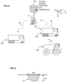
Figure 4 shows a diagrammatical block diagram of the system promoted in the present disclosure, -
Figure 5 is a chart illustrating the frame collection basic process by a radar scanner unit, -
Figure 6 illustrates an example of aperture angles of the radar frame collection process, -
Figure 7 illustrates an example of a displayed map, -
Figure 8 illustrates a diagrammatical block diagram of the overall system promoted in the present disclosure, -
Figure 9 illustrates an example of a section of a pothole, -
Figure 10 illustrates a map/navigation display with different itinerary possibility associated with their potholes severity ratings. - In the figures, the same references denote identical or similar elements. For sake of clarity, various elements may not be represented at scale.
-
Figure 1 shows diagrammatically a top view of a road where one vehicle V is moving. The present disclosure relates to dealing with poor road surface quality. Also of particular interest here are structurally damaged portions of road infrastructure at the center or at the borders of the road. - There are shown various examples of potholes in
figure 1 . There can beindividual potholes continuous area 92 of uneven and damaged road portion. Such continuous area of uneven and damaged road portion can concern aborder 98 of the road. - In the present disclosure potholes are generically denoted by
reference 9. - Potholes can be located in road lane that is to be travelled by the vehicle. Potholes can also be located in another road lane, where vehicle(s) travel in the same direction, or where vehicles can travel in opposite direction. The general longitudinal motion direction of the vehicle V is denoted X. We note here that axis X is generally not horizontal. First of all, the inclination of the road can result in a longitudinal axis oriented upwards or downwards. Secondly given the suspension of the vehicle, the orientation of longitudinal axis is not necessarily parallel to the road surface, there are swing oscillations (pitch and roll). In addition, beside dynamic behaviour, the vehicle can exhibit a pitch-up posture or a pitch-down posture, notably according to carried payload.
- Here are considered truck of all types, including off-road transport. The truck considered here can be the traction unit in a tractor/trailer configuration or it can be a utility 'carrier' truck. Of particular interest here we also consider off road trucks like the ones used in the mining industry. We consider here not only vehicles/truck circulating on public roads but also vehicles/truck circulating elsewhere like in private premises or semi-private premises. We consider here vehicles/truck used in mining resorts.
- Consequently, the term 'road' is to be construed broadly including track, paths or the like. The borders of such track/road may be clearly identified in some cases, but also in other cases the borders cannot be clearly identified. Stated otherwise, the lateral shoulders may be of any structure.
- We define an area of
interest 66. Said area ofinterest 66 is located in front of and ahead the vehicle of interest. The area ofinterest 66 includes at least a surface of a road to be traveled by the vehicle. The area of interest is 3D, i.e. a volume of interest. Generally the area of interest encompasses the whole width RW of the road (seefigure 1 ). - The height of the volume of interest is slightly greater than a height H1 where the sensing device (to be discussed later) is arranged on the vehicle. H1 is taken with the ground as reference as shown at
figure 2 . - In the vertical dimension the area of interest encompasses the road surface and beneath. More details will be discussed later about the area of
interest 66. - The forward velocity of the vehicle denoted VSP.
- Besides the imaging unit, the vehicle V comprises a geolocation system receiver, configured to receive signals from
satellites 75 and to deliver therefrom a plurality of successive geolocations GPS(i), the index i denotes the rank in the series of successive geolocations. - Vehicle speed VSP can be obtained from the wheel speed of the wheels or from the derivative of the successive geolocations GPS(i), or both.
- Geolocations systems of this type are known per se, such as GPS, Galileo, Glonass or the like, and therefore not described in detail herein.
- Also, it is contemplated to use RTK GPS or differential GPS.
- According to the expected dynamic behavior of the vehicle, it is contemplated to use of low-pass filter to discard jitter from the raw signals.
- The electronic control unit 6 (to be discussed later) can determine from geolocation signals the current geolocation of the vehicle.
- Regarding now cartography, there may be provided a local cartography map, as known per se. Further regarding cartography, there may be provided a remote cartography map, downloaded upon request and desired geolocations as also known per se. Hybrid configurations are also considered, where basic map can be present in a local cartography map, whereas complementary maps and/or traffic real-time information are downloaded on need from one or more remote servers.
- In any case, cartography information can comprise the type of each road or track segment (width, number of lane(s) one/two ways, flat/uphill/downhill, material of pavement, type of shoulder, ...)
- The map is displayed on a cartography display 7 provided for the vehicle driver.
- Further regarding geolocation, in addition to GPS or the like, a dead reckoning function can be provided. Integration of speed and steering angle is one possible solution.
- Recourse to an inertial platform (IMU) with simple/double integration of basic speed/acceleration can also be considered. When SLAM process is not possible (bad weather condition or dark conditions), the inertial Measurement Unit can provide precise localization of the vehicle on the road, and position of potholes can be displayed to the truck driver with a good accuracy.
- There is provided on the vehicle a
sensing device 4. The sensing device is preferably installed at the uppermost possible position looking ahead, for example shown in thefigures 2 and 3 , at the top of the front face of the cabin. - H1 denoted the height position of the sensing device with regard to the ground reference. H1 is typically comprised between 200 cm and 300 cm, preferably comprised between 220 cm and 260 cm. It should be noted that a sensing device at this height H1 is not prone to splashing. By contrast, in other known systems, sensors located under the vehicle chassis or at the shock absorbers are bound to be dirtied quickly by splashing of mud.
- Preferably, the promoted system here is deprived of sensor(s) below a 1 meter threshold from the ground level.
- The sensing device comprises at least a radar device, i.e. a radar-type scanner, simply 'radar' in short. The
radar 51 uses bursts of electromagnetic waves Tx and echoes Rx coming back from objects present in the scene. As known per se, cfFig 5 , time difference ΔT between transmitting burst instant and backscatter echo reception is proportional to the distance separating the radar from the surface of an object were the electromagnetic waves have bounced back. Unlike some other detection system, radar device operation is not impaired by darkness, and is not impaired by light rain of light fog. - Either a time difference or an equivalent frequency deviation (FMCW Chirp radar variant) is measured to infer the distance.
- Also the amplitude Amp and phase of each echo is recorded. The amplitude and phase of the echoes Rx depend on the nature of the object that backscatters the impinging electromagnetic waves Tx. It is understood that a pothole creates an echo different from an even road surface. Also a pothole filled with water or mud creates a further different echo from an even road surface or a void pothole.
- The electromagnetic waves used for
radar unit 51 have a carrier frequency comprised between 10 MHz and 100 GHz. In one embodiment, theradar unit 51 is a 77 GHz radar scanner. In one embodiment, the radar unit is a 24 GHz radar scanner. - The
radar unit 51 exhibits a first field of view expressed in an angular scan sector (θazi, cpelev). This field of view encompasses the above mentioned area ofinterest 66. - Angle θ denotes azimuthal sweep, whereas angle ϕ denotes vertical sweep.
- Given the rather narrow width of the area of interest, the scan of the total angular scan sector (θazi, ϕelev) takes little time. The frequency of scan repetition is comprised between 20 Hz and 60 Hz, i.e. each point of the field of view is scanned 20 to 60 times per second.
- As shown in
figure 2 , X1 denote the longitudinal axis of the vehicle at the level of the sensing device. Angle ϕ is the vertical deviation versus X1. Angle ϕ' denotes the angle of theburst ray 40 versus the ground. Angle ϕ' may differ from angle ϕ with respect to suspension or the static posture (pitch up or pitch down). In a particular case shown atfigure 2 , ϕ' = ϕ. - As shown in
figure 6 , the angular scan domain can be trapezoidal. The more pronounced is the lookdown direction, the wider is the azimuthal angular range θ. Conversely, the more horizontal is lidar beam, the narrower is the azimuthal angular range θ. Infigure 6 ϕ is shown in the negative range, from a ϕ=0 aligned with X1. - More precisely, azimuthal sweep θ is comprised between -θ2 and θ2 when angle ϕ corresponds to a max look down attitude. By contrast, azimuthal sweep θ is comprised between -θ1 and θ1 when angle ϕ corresponds to a look ahead attitude (angle ϕ =0°). In one embodiment, angle ϕ scan sector is 85° as shown at
figures 3 and6 . In one embodiment, limit angle θ1 is comprised between 10° and 15°, limit angle θ2 is comprised between 20° and 45°. - According to one example, the angular scan domain is symmetrical with regard to the longitudinal axis (left/right symmetry). There may be a
proportional link 660 between azimuth and elevation, wherein the total azimuthal range is a function of a elevation (negative), as illustrated atfigure 6 . - According to one option, the angular scan domain can be enlarged on the side of the steering direction, i.e. this means enlarging the area of interest on the turning side.
- According to one option, the angular scan domain can be enlarged or biased according the itinerary to be followed. The area of interest can be defined in accordance with the geolocation map (cartography and current position), the area of interest matches with the road curvature ahead.
- According to a particular aspect of the present disclosure, the radar device is a SAR Radar.
- When the vehicle moves, a particular point is scanned several times with a slightly different impinging angle. The successive series of echoes results in a plurality of information with amplitude and phase as already exposed above. Processing of the series of echoes, either at low level in the radar device or at the computing unit 6, allows finding real potholes and shed other echoes and avoiding thereby to record false positives.
- Stated otherwise, firstly candidate pothole(s) are gathered from the radar device data flow. Then further processing the data flow helps finding out confirmed potholes among the candidate potholes.
- In the present document, potholes retrieved during the above process by the sensing device are called 'first' by contrast with other potholes recorded previously or known from other source device are called 'second'.
- The data flow further processing can be performed through digital filters, fast Fourier transform, neural network, etc...
- In addition, vehicle suspension is considered, pitch and roll movement are taken into account. According to one solution, the radar device can be mounted on a stabilization platform with a mechanical low pass filtering that discards all the undesirable vibrations. According to another solution, data obtained from a new radar scan can be 'registered' to the previous one, in other words the scan is realigned with the help of a landmark or with the help of an ICP algorithm (ICP : Iterative Closest Point).
- As illustrated at
Figure 4 , the system comprises the onboard control unit 6 cartography display 7, theradar device 51, a memory ordatabase 8, which can be integrated or not in the onboard control unit 6. Further, the system comprises a wireless/cellular communication means 68. Thanks to the wireless/cellular communication means 68, the control unit 6 is internet enabled and can access a remote ordatabase 80. - Optionally, the system may comprise the
lidar device 52. - Optionally, the system may comprise one 3D camera or time-of-flight camera (ToF camera). Alternately, the system may comprise two cameras 53,54 for stereoscopic vision. Lidar and camera(s) can be located at the top of the cabin, but not necessarily at the same location of the radar device. The
radar device 51 may be located on the median vertical plane. - Data gathered by the lidar or the camera(s) can be used to complement data gathered by the radar device.
- From data flow delivered by the radar device, it is determined first candidate potholes formed on the road surface. Candidate potholes can correspond to predetermined echoes, or series of echoes of the same impinged area with successive radar scans. Predetermined echoes can be stored in lookup tables, reference tables or the like. There also may be provided a learning mechanism.
- Each of the potholes can be characterized by a set of size characteristics, comprising at least one of : its
depth 9D, itswidth 9W, itslength 9L. (Seefigures 1 and9 ). - There may be provided a pothole rating according to severity with regard to safety and/or potential damage to vehicle. This consists in allocating a severity rating SR to each of the potholes (notably the first confirmed potholes).
- Severity rating can be defined with the help of a severity scale ranging from 1 to 10. According to one example, a shallow recess will be rated 1, a substantial pothole would be rated 5 and a deep pothole would be rated 10.
- The severity rating is possibly calculated as a function of its
depth 9D. - Other criteria can also be taken into account like the longitudinal length of the pothole or the damaged area. severity rating SR can be expressed as a function of the size characteristics of the considered pothole. Such as SR = f (depth, width, length).
- A severity rating can also be allocated to a large damaged area, i.e. an area wider than a single individual pothole.
- As illustrated in
figures 7 and8 , the knowledge of potholes can be shared between various road users. - Indeed the proposed method includes sharing pothole information with other parties. This means making available first confirmed potholes and associated geolocation, preferably with its size characteristics, to a third party. Such third party can be a
remote server 3. Such third party can be one or more neighboring vehicle(s) via Car2Car communication. - In practice there is provided an
uplink 18 enabling vehicles equipped with the radar device to transmit data to aremote server 3. - There is also provided a
down link 28 enabling vehicles to receive data from aremote server 3. - With reference to
Figure 8 , vehicles V61 and V62 transmit their information throughuplink 18 to the remote server 3 (or as illustrated atfigure 4 generally to one or more unit(s) in the cloud). Vehicles V61 and V62 also receive data about potholes viadownlink 28 from server(s) or cloud service(s). - We note that even vehicles not equipped with radar sensing device like the truck referenced V63 at
figure 8 can take advantage of the knowledge of potholes. V63 only displays second potholes, since it cannot detect themselves the potholes in real time. - With reference to
Figure 7 , vehicles V4 V5 V6 V7 V8 V9 circulate on a network of road or tracks.Potholes 9 and damagedareas 99 are comprised in the common database shared between road users. This knowledge can be located in asingle pothole database 80, or shared between several memory units. - In the illustrated example vehicles V5 and V8 scan road surface determine pothole and transmit relative data to the remote server.
- All other vehicles can take advantage of the updated information at a short term timeline.
- With reference to
Figure 10 , there may be provided a navigation service helping a truck driver to choose the best itinerary when two or more options are possible. - In a manner very similar to a conventional navigation service, the navigation calculation can show various possible itineraries to go from a departure location denoted A to a destination location B. The display shows the various proposed itineraries to go from A to B, each itinerary being displayed together with a respective cumulated pothole severity rating. The location of outstanding pothole can be displayed with colors and icons.
- Alternative route according to potholes ratings.
- It is preferred to display, on the cartography display, the potholes with various icons and/or colors, each of the first and second potholes together with their respective severity rating. This provides intuitive and comprehensive display for the truck drivers.
- Also the first potholes can be shown differently with regard to second potholes. A first color or a first icon can be used to show first potholes whereas a second color or a second icon can be used to show second potholes.
- When a pothole is no longer detected, it is not reported any longer. There is a fading process in the database which lead to delete a pothole that has been repaired. A pothole may disappear from the list in passive mode, i.e. no longer being reported. Alternatively, or in addition, a pothole may disappear from the list actively in response to notification of repair.
- With the sensing device placed substantially at some height that say between 2 m and 3m50, potholes can be detected by the lidar scan at a distance ahead from the track. The forward detection distance is at least 5 m from the truck front end. In some embodiments, the forward detection distance is at least 10 m from the truck front end. With such anticipation, the truck driver can efficiently avoid the more severe potholes, for example by a steering correction.
Claims (15)
- A method for at least detecting, localizing, and reporting potholes (9) on a road, where the method is being carried out in a system comprising a sensing device (4) mounted on a vehicle (V), a cartography display mounted on the vehicle, and an onboard control unit (6) aboard the vehicle, the sensing device comprising at least a radar device, the method comprising:a- scanning with the sensing device an area of interest (66) in front of and ahead the vehicle, the area of interest including at least a surface of a road traveled by the vehicle, the sensing device outputting a data flow,b1- identifying, in the data flow, first candidate potholes formed on the road surface,b2- further processing the data flow to find out first confirmed potholes among the first candidates potholes,c- allocating a geolocation to each of the first confirmed potholes,d- displaying, on the cartography display (7), first potholes with their localization superimposed on the map.
- The method according to claim 1, wherein the radar device is a SAR-type radar, namely a synthetic aperture radar device.
- The method according any of the claims 1 to 2, wherein at step b2-, first candidates potholes are extracted from the data flow, and a likelihood of a confirmed pothole is assessed with subsequent radar scans, and such pothole thereby confirmed being selected as a first confirmed pothole.
- The method according to any of the claims 1 to 3, further comprising :
b3- characterizing each of the first confirmed potholes by a set of size characteristics, comprising at least one of : its depth (9D), its width (9W), its length (9L). - The method according to 4, further comprising :- allocating a severity rating to each of the first confirmed potholes, possibly at least as a function of its depth (9D).
- The method according to any of the claims 1 to 5, further comprising :- sharing (making available) first confirmed potholes and associated geolocation, preferably with its size characteristics, to a third party i.e. remote server and/or Car2Car communication.
- The method according to any of the claims 1 to 6, further comprising :- receiving second potholes data from a remote database or a local database.
- The method according to 7, further comprising :
d2- displaying, on the cartography display, second potholes. - The method according to claim 7, further comprising
d3- displaying, on the cartography display, with various icons and/or colors, each of the first and second potholes together with their severity rating. - The method according to any of the claims 1 to 9, wherein the sensing device comprises, besides the radar device, a lidar device (52) and/or a Time-of-Flight camera (53,54).
- The method according to any of the claims 1 to 10, further comprising b10- identifying in the data flow generally damaged and/or uneven portions (92,98) on the road surface.
- The method according to any of the claims 1 to 11, wherein the area of interest encompasses the whole width (RW) of the road/track.
- The method according to any of the claims 1 to 12, further comprising :
d2- displaying, on the cartography display, one or more itinerary to go from a departure location (A) to a destination location (B), each of the one or more itinerary being displayed with a cumulated pothole severity rating. - A system an imaging device mounted on a vehicle, a cartography display mounted on the vehicle, and an onboard control unit (6) aboard the vehicle, configured to carry out the method according to any of the claims 1 to 13.
- The system according to claim 14, further comprising a remote server (3) and a data link allowing data exchange between the remote server (3) and the onboard control unit (6).
Priority Applications (3)
| Application Number | Priority Date | Filing Date | Title |
|---|---|---|---|
| EP21200174.7A EP4160249A1 (en) | 2021-09-30 | 2021-09-30 | System for detecting, localizing and sharing potholes |
| CN202211030784.3A CN115892025A (en) | 2021-09-30 | 2022-08-26 | System for detecting, locating and sharing potholes |
| US17/939,051 US20230108406A1 (en) | 2021-09-30 | 2022-09-07 | System for detecting, localizing, and sharing potholes |
Applications Claiming Priority (1)
| Application Number | Priority Date | Filing Date | Title |
|---|---|---|---|
| EP21200174.7A EP4160249A1 (en) | 2021-09-30 | 2021-09-30 | System for detecting, localizing and sharing potholes |
Publications (1)
| Publication Number | Publication Date |
|---|---|
| EP4160249A1 true EP4160249A1 (en) | 2023-04-05 |
Family
ID=78414156
Family Applications (1)
| Application Number | Title | Priority Date | Filing Date |
|---|---|---|---|
| EP21200174.7A Pending EP4160249A1 (en) | 2021-09-30 | 2021-09-30 | System for detecting, localizing and sharing potholes |
Country Status (3)
| Country | Link |
|---|---|
| US (1) | US20230108406A1 (en) |
| EP (1) | EP4160249A1 (en) |
| CN (1) | CN115892025A (en) |
Families Citing this family (1)
| Publication number | Priority date | Publication date | Assignee | Title |
|---|---|---|---|---|
| CN116189133B (en) * | 2023-04-26 | 2023-07-28 | 宜宾闪马智通科技有限公司 | Road inspection judging method and device |
Citations (3)
| Publication number | Priority date | Publication date | Assignee | Title |
|---|---|---|---|---|
| US20140168001A1 (en) * | 2012-12-13 | 2014-06-19 | Continental Automotive Systems, Inc. | Negative obstacle detection with stereo camera and long range radar |
| US20200254995A1 (en) * | 2019-02-12 | 2020-08-13 | Mando Corporation | Vehicle and method of controlling the same |
| US20200269877A1 (en) * | 2017-12-22 | 2020-08-27 | Nissan North America, Inc. | Solution Path Overlay Interfaces For Autonomous Vehicles |
Family Cites Families (6)
| Publication number | Priority date | Publication date | Assignee | Title |
|---|---|---|---|---|
| US9416499B2 (en) * | 2009-12-31 | 2016-08-16 | Heatwurx, Inc. | System and method for sensing and managing pothole location and pothole characteristics |
| US9626763B1 (en) * | 2015-02-25 | 2017-04-18 | Lytx, Inc. | Pothole detection |
| US11073401B1 (en) * | 2017-03-10 | 2021-07-27 | Skydio, Inc. | Road network optimization based on vehicle telematics information |
| US11015944B2 (en) * | 2017-08-01 | 2021-05-25 | Ford Global Technologies, Llc | Method and apparatus for dynamic navigation modification |
| US20190378055A1 (en) * | 2018-06-06 | 2019-12-12 | Lyft, Inc. | Systems and methods for determining allocation of personal mobility vehicles |
| US11380147B2 (en) * | 2019-09-04 | 2022-07-05 | Pony Ai Inc. | System and method for determining vehicle navigation in response to broken or uncalibrated sensors |
-
2021
- 2021-09-30 EP EP21200174.7A patent/EP4160249A1/en active Pending
-
2022
- 2022-08-26 CN CN202211030784.3A patent/CN115892025A/en active Pending
- 2022-09-07 US US17/939,051 patent/US20230108406A1/en active Pending
Patent Citations (3)
| Publication number | Priority date | Publication date | Assignee | Title |
|---|---|---|---|---|
| US20140168001A1 (en) * | 2012-12-13 | 2014-06-19 | Continental Automotive Systems, Inc. | Negative obstacle detection with stereo camera and long range radar |
| US20200269877A1 (en) * | 2017-12-22 | 2020-08-27 | Nissan North America, Inc. | Solution Path Overlay Interfaces For Autonomous Vehicles |
| US20200254995A1 (en) * | 2019-02-12 | 2020-08-13 | Mando Corporation | Vehicle and method of controlling the same |
Also Published As
| Publication number | Publication date |
|---|---|
| US20230108406A1 (en) | 2023-04-06 |
| CN115892025A (en) | 2023-04-04 |
Similar Documents
| Publication | Publication Date | Title |
|---|---|---|
| JP7090597B2 (en) | Methods and systems for generating and using location reference data | |
| EP3130891B1 (en) | Method for updating a server database containing precision road information | |
| US9528834B2 (en) | Mapping techniques using probe vehicles | |
| EP3130945B1 (en) | System and method for precision vehicle positioning | |
| EP3131020B1 (en) | System and method of a two-step object data processing by a vehicle and a server database for generating, updating and delivering a precision road property database | |
| US10705220B2 (en) | System and method for ground and free-space detection | |
| US20200217950A1 (en) | Resolution of elevation ambiguity in one-dimensional radar processing | |
| CN104217590B (en) | Method for making the electronic controller in main vehicle determine traffic density | |
| US10082797B2 (en) | Vehicle radar perception and localization | |
| JP6694395B2 (en) | Method and system for determining position relative to a digital map | |
| CN113002396B (en) | A environmental perception system and mining vehicle for automatic driving mining vehicle | |
| US20180025632A1 (en) | Mapping Techniques Using Probe Vehicles | |
| US20210191399A1 (en) | Real-Time Adjustment Of Vehicle Sensor Field Of View Volume | |
| US11475678B2 (en) | Lane marker detection and lane instance recognition | |
| US10705534B2 (en) | System and method for ground plane detection | |
| WO2018017793A1 (en) | System and method for creating, updating, and using maps generated by probe vehicles | |
| US11544940B2 (en) | Hybrid lane estimation using both deep learning and computer vision | |
| CN105937912A (en) | Map data processing device for vehicle | |
| JP2003506785A (en) | Method and apparatus for stationary object detection | |
| US6285949B1 (en) | Method and device for extensive traffic situation monitoring | |
| EP4137846A1 (en) | High-precision map generation method, localization method, and device | |
| US20230108406A1 (en) | System for detecting, localizing, and sharing potholes | |
| CN112884892B (en) | Unmanned mine car position information processing system and method based on road side device | |
| Mimuro et al. | Concept study of a self-localization system for snow-covered roads using a four-layer laser scanner | |
| US20050060090A1 (en) | Vehicle-type measurement system |
Legal Events
| Date | Code | Title | Description |
|---|---|---|---|
| PUAI | Public reference made under article 153(3) epc to a published international application that has entered the european phase |
Free format text: ORIGINAL CODE: 0009012 |
|
| STAA | Information on the status of an ep patent application or granted ep patent |
Free format text: STATUS: THE APPLICATION HAS BEEN PUBLISHED |
|
| AK | Designated contracting states |
Kind code of ref document: A1 Designated state(s): AL AT BE BG CH CY CZ DE DK EE ES FI FR GB GR HR HU IE IS IT LI LT LU LV MC MK MT NL NO PL PT RO RS SE SI SK SM TR |
|
| STAA | Information on the status of an ep patent application or granted ep patent |
Free format text: STATUS: REQUEST FOR EXAMINATION WAS MADE |
|
| 17P | Request for examination filed |
Effective date: 20230613 |
|
| RBV | Designated contracting states (corrected) |
Designated state(s): AL AT BE BG CH CY CZ DE DK EE ES FI FR GB GR HR HU IE IS IT LI LT LU LV MC MK MT NL NO PL PT RO RS SE SI SK SM TR |