EP4160187A1 - Environmental enclosure for a gas sensor for use in a transport vehicle - Google Patents
Environmental enclosure for a gas sensor for use in a transport vehicle Download PDFInfo
- Publication number
- EP4160187A1 EP4160187A1 EP22199212.6A EP22199212A EP4160187A1 EP 4160187 A1 EP4160187 A1 EP 4160187A1 EP 22199212 A EP22199212 A EP 22199212A EP 4160187 A1 EP4160187 A1 EP 4160187A1
- Authority
- EP
- European Patent Office
- Prior art keywords
- housing
- refrigerant
- detection assembly
- subassembly
- opening
- Prior art date
- Legal status (The legal status is an assumption and is not a legal conclusion. Google has not performed a legal analysis and makes no representation as to the accuracy of the status listed.)
- Pending
Links
Images

Classifications
-
- G—PHYSICS
- G01—MEASURING; TESTING
- G01N—INVESTIGATING OR ANALYSING MATERIALS BY DETERMINING THEIR CHEMICAL OR PHYSICAL PROPERTIES
- G01N21/00—Investigating or analysing materials by the use of optical means, i.e. using sub-millimetre waves, infrared, visible or ultraviolet light
- G01N21/17—Systems in which incident light is modified in accordance with the properties of the material investigated
- G01N21/25—Colour; Spectral properties, i.e. comparison of effect of material on the light at two or more different wavelengths or wavelength bands
- G01N21/255—Details, e.g. use of specially adapted sources, lighting or optical systems
-
- B—PERFORMING OPERATIONS; TRANSPORTING
- B60—VEHICLES IN GENERAL
- B60H—ARRANGEMENTS OF HEATING, COOLING, VENTILATING OR OTHER AIR-TREATING DEVICES SPECIALLY ADAPTED FOR PASSENGER OR GOODS SPACES OF VEHICLES
- B60H1/00—Heating, cooling or ventilating devices
- B60H1/00642—Control systems or circuits; Control members or indication devices for heating, cooling or ventilating devices
- B60H1/00978—Control systems or circuits characterised by failure of detection or safety means; Diagnostic methods
-
- B—PERFORMING OPERATIONS; TRANSPORTING
- B60—VEHICLES IN GENERAL
- B60H—ARRANGEMENTS OF HEATING, COOLING, VENTILATING OR OTHER AIR-TREATING DEVICES SPECIALLY ADAPTED FOR PASSENGER OR GOODS SPACES OF VEHICLES
- B60H1/00—Heating, cooling or ventilating devices
- B60H1/32—Cooling devices
- B60H1/3204—Cooling devices using compression
- B60H1/3232—Cooling devices using compression particularly adapted for load transporting vehicles
-
- G—PHYSICS
- G01—MEASURING; TESTING
- G01M—TESTING STATIC OR DYNAMIC BALANCE OF MACHINES OR STRUCTURES; TESTING OF STRUCTURES OR APPARATUS, NOT OTHERWISE PROVIDED FOR
- G01M3/00—Investigating fluid-tightness of structures
- G01M3/002—Investigating fluid-tightness of structures by using thermal means
-
- G—PHYSICS
- G01—MEASURING; TESTING
- G01N—INVESTIGATING OR ANALYSING MATERIALS BY DETERMINING THEIR CHEMICAL OR PHYSICAL PROPERTIES
- G01N21/00—Investigating or analysing materials by the use of optical means, i.e. using sub-millimetre waves, infrared, visible or ultraviolet light
- G01N21/17—Systems in which incident light is modified in accordance with the properties of the material investigated
- G01N21/25—Colour; Spectral properties, i.e. comparison of effect of material on the light at two or more different wavelengths or wavelength bands
- G01N21/31—Investigating relative effect of material at wavelengths characteristic of specific elements or molecules, e.g. atomic absorption spectrometry
- G01N21/35—Investigating relative effect of material at wavelengths characteristic of specific elements or molecules, e.g. atomic absorption spectrometry using infrared light
- G01N21/3504—Investigating relative effect of material at wavelengths characteristic of specific elements or molecules, e.g. atomic absorption spectrometry using infrared light for analysing gases, e.g. multi-gas analysis
-
- B—PERFORMING OPERATIONS; TRANSPORTING
- B60—VEHICLES IN GENERAL
- B60P—VEHICLES ADAPTED FOR LOAD TRANSPORTATION OR TO TRANSPORT, TO CARRY, OR TO COMPRISE SPECIAL LOADS OR OBJECTS
- B60P3/00—Vehicles adapted to transport, to carry or to comprise special loads or objects
- B60P3/20—Refrigerated goods vehicles
-
- F—MECHANICAL ENGINEERING; LIGHTING; HEATING; WEAPONS; BLASTING
- F25—REFRIGERATION OR COOLING; COMBINED HEATING AND REFRIGERATION SYSTEMS; HEAT PUMP SYSTEMS; MANUFACTURE OR STORAGE OF ICE; LIQUEFACTION SOLIDIFICATION OF GASES
- F25B—REFRIGERATION MACHINES, PLANTS OR SYSTEMS; COMBINED HEATING AND REFRIGERATION SYSTEMS; HEAT PUMP SYSTEMS
- F25B2500/00—Problems to be solved
- F25B2500/22—Preventing, detecting or repairing leaks of refrigeration fluids
- F25B2500/222—Detecting refrigerant leaks
-
- F—MECHANICAL ENGINEERING; LIGHTING; HEATING; WEAPONS; BLASTING
- F25—REFRIGERATION OR COOLING; COMBINED HEATING AND REFRIGERATION SYSTEMS; HEAT PUMP SYSTEMS; MANUFACTURE OR STORAGE OF ICE; LIQUEFACTION SOLIDIFICATION OF GASES
- F25B—REFRIGERATION MACHINES, PLANTS OR SYSTEMS; COMBINED HEATING AND REFRIGERATION SYSTEMS; HEAT PUMP SYSTEMS
- F25B49/00—Arrangement or mounting of control or safety devices
- F25B49/005—Arrangement or mounting of control or safety devices of safety devices
-
- G—PHYSICS
- G01—MEASURING; TESTING
- G01N—INVESTIGATING OR ANALYSING MATERIALS BY DETERMINING THEIR CHEMICAL OR PHYSICAL PROPERTIES
- G01N2201/00—Features of devices classified in G01N21/00
- G01N2201/02—Mechanical
- G01N2201/022—Casings
Definitions
- Exemplary embodiments of the present invention relate to refrigeration systems, and more particularly, to a detection assembly and a refrigeration system associated with the detection assembly for detecting leaks of moderate to low global warming potential (GWP) refrigerants.
- GWP global warming potential
- a wide variety of technologies exist for cooling applications including but not limited to evaporative cooling, convective cooling, or solid state cooling such as electrothermic cooling.
- One of the most prevalent technologies in use for residential and commercial refrigeration and air conditioning is the vapor compression refrigerant heat transfer loop.
- the refrigerant commonly used in such systems such as R134A or R410A, has a high GWP.
- R134A or R410A has a high GWP.
- these refrigerants are effective coolants, the effect they can have on the environment has led to the institution of requirements that new refrigerants, which have moderate-to-low GWP values, be employed instead.
- Moderate-to-low GWP refrigerants i.e., A2L refrigerants
- A2L refrigerants can be mildly flammable, however, and thus their use in air conditioning systems can present risks that need to be addressed.
- refrigerant leaks are possible in air conditioning systems, it is desirable to have an environmentally robust leak detection systems in place when A2L refrigerants are in use in heating, ventilation, air conditioning and refrigeration (HVAC&R) products and other similar systems.
- HVAC&R heating, ventilation, air conditioning and refrigeration
- a refrigerant detection assembly operable to detect refrigerant mixed with air.
- the refrigerant detection assembly includes a housing having an internal cavity fluidly connected with an ambient atmosphere surrounding the housing via an opening; a subassembly mounted within the internal cavity that includes an air chamber fluidly connected with the internal cavity, a non-dispersive infrared sensor operably coupled to the air chamber, a printed circuit board operably coupled to the non-dispersive infrared sensor, and a heat conduction plate mechanically and thermally coupled to the printed circuit board.
- At least one insulator is arranged within the internal cavity at a position between a portion of the subassembly and the housing.
- a shell is connectable to the housing in overlapping arrangement with the opening formed in the housing.
- the shell has at least one shell opening formed therein such that a flow path extends from the shell opening, through the opening formed in the housing to the internal cavity, and into the air chamber.
- the non-dispersive infrared sensor includes a light source and a detector element, the light source and the detector element being mounted to the printed circuit board.
- the air chamber is positioned adjacent to a first side of the printed circuit board, and the heat conduction plate is arranged adjacent to a second, opposite side of the printed circuit board.
- the subassembly further comprises at least one active heating element operably coupled to the non-dispersive infrared sensor.
- the air chamber is defined between a top sensor cover and a bottom sensor cover and at least one of the top sensor cover and the bottom sensor cover has a hole formed therein, the subassembly further comprising a film disposed in overlapping arrangement with the hole, wherein the film is permeable to gas and impermeable to liquid.
- the refrigerant detection assembly may comprise a film disposed in overlapping arrangement with the opening, wherein the film is permeable to gas and impermeable to liquid.
- the housing further comprises a cover and a bottom
- the at least one insulator further comprises a first insulator disposed between the subassembly and the cover and a second insulator positioned between the subassembly and the cover.
- At least one of the first insulator and the second insulator has a groove complementary to a corresponding portion of the subassembly receivable therein.
- the at least one insulator further comprises a shell insulator positioned between the shell and the housing.
- a refrigerated container system that includes: a refrigeration system including a closed loop refrigerant circuit having a refrigerant circulating therein; a container having a cargo area arranged in fluid communication with the refrigeration system; and a refrigerant detection assembly.
- the refrigerant detection assembly is operable to detect refrigerant from the closed loop refrigerant circuit mixed with air.
- the refrigerant detection assembly includes: a housing having an internal cavity and an opening such that a flow path extends from the opening into the internal cavity; and a subassembly arranged within the internal cavity.
- the subassembly includes: an air chamber fluidly connected to the internal cavity, a non-dispersive infrared sensor operably coupled to the air chamber, a printed circuit board operably coupled to the non-dispersive infrared sensor, and a heat conduction plate thermally coupled to the printed circuit board. At least one insulator is used to mount the subassembly within the internal cavity.
- the refrigeration system includes an evaporator coil and the refrigerant detection assembly is mounted adjacent to the evaporator coil.
- the evaporator coil includes at least one tube arranged within an evaporator housing, and the refrigerant detection assembly is mounted to the evaporator housing.
- the container is a cargo container transportable by a watercraft.
- the refrigerant detection assembly is operable to detect a leak within the closed loop refrigerant circuit within ten seconds of being exposed to 100% of a lower flammability limit.
- the refrigerant detection assembly is operable to detect a leak within the closed loop refrigerant circuit when the refrigerant measured by the non-dispersive infrared sensor is at least 25% of a lower flammability limit.
- the non-dispersive infrared sensor is integrally formed with the printed circuit board.
- the subassembly further comprises at least one active heating element operably coupled to the non-dispersive infrared sensor.
- the air chamber is defined between a top sensor cover and a bottom sensor cover and at least one of the top sensor cover and the bottom sensor cover has a hole formed therein, the subassembly further comprising a film disposed in overlapping arrangement with the hole, wherein the film is permeable to gas and impermeable to liquid.
- the refrigerant detection assembly further comprises a shell connectable to the housing in overlapping arrangement with the opening, the shell having at least one shell opening formed therein such that a flow path extends from the shell opening, through the opening formed in the housing to the internal cavity, and into the air chamber.
- the film being permeable to gas and impermeable to liquid.
- the refrigeration detection assembly of the second aspect of the invention may be in accordance with the refrigeration detection system of the first aspect of the invention, optionally in accordance with any optional form thereof.
- the transport refrigeration system 20 is shown as a trailer system.
- the system 20 includes a cargo container or trailer 22 being towed or otherwise transported by a tractor 24 including an operator's compartment or cab 26 and also including an engine (not shown), which acts as the drivetrain system of the system 20.
- a refrigeration unit 30 is configured to maintain cargo located within the container 22 at a selected temperature by cooling the cargo space of the container 22.
- the refrigeration unit 30 is typically mounted at the front wall 28 of the container 22. Together, the refrigeration unit 30 and the cargo container 22 may form a refrigerated container system. It should be appreciated by those of skill in the art that embodiments described herein may be applied to any transport refrigeration system such as, for example shipping containers that are shipped by rail, sea (via a watercraft), or any other suitable container, without use of a tractor 24.
- the refrigeration unit 30 is divided into two sections, a condenser section 30a and an evaporator section 30b.
- the condenser section 30a may disposed generally forward of a front wall of the container 22 and is arranged in fluid communication with the ambient atmosphere external to the trailer 22 and the refrigeration unit 30 to exchange air and heat therewith.
- the evaporator section 30b is not in fluid communication with the ambient atmosphere to control temperature within the trailer 22.
- the refrigeration unit 30 includes a compressor 32, a condenser coil 34, an expansion device 36, and an evaporator coil 38 fluidly connected to one another to form a closed loop system.
- a fluid R such as a refrigerant for example, is configured to flow from the compressor 32 to the condenser coil 34, expansion device 36, and evaporator coil 38 in series.
- a condenser fan 40 such as driven by a condenser motor (not shown) is configured to move a flow of air across an exterior of the condenser coil 34
- an evaporator fan 42 such as driven by an evaporator motor (not shown) may be used to drive a flow of fluid (air) across an exterior of the evaporator coil 38.
- the refrigerant R circuiting within the refrigeration unit 30 is an A2L refrigerant.
- the classification of refrigerant is based upon American Society of Heating, Refrigerating and Air-Conditioning (ASHRAE) Standard 34.
- ASHRAE American Society of Heating, Refrigerating and Air-Conditioning
- the standard evaluates each refrigerant's flammability and toxicity and gives it a class referenced as a letter and number combination.
- the letter refers to the refrigerants' toxicity, and is based on the particular refrigerant's occupational exposure limit (OEL).
- OEL occupational exposure limit
- the number adjacent to the letter refers to the refrigerant's flammability, and is based on the burning velocity (BV), heat of combustion (HOC), and lower flammability limits (LFL) of the particular refrigerant.
- BV burning velocity
- HOC heat of combustion
- LFL lower flammability limits
- the refrigerant R within the closed loop refrigerant circuit of the refrigeration unit 30 may, in rare instances, leak.
- the refrigeration unit 30 includes at least one refrigerant detection assembly 50 operable to detect a refrigerant leak therein.
- the evaporator section 30b includes at least one refrigerant detection assembly 50.
- the at least one refrigerant detection assembly 50 may be mounted to the evaporator housing of the evaporator coil 38 to detect gaseous refrigerant located external to at least one tube 44 of the evaporator coil 38.
- a refrigerant detection assembly 50 is alternatively or additionally arranged at any suitable location relative to the refrigeration unit 30 or the container 22 to detect a leak therein are also within the scope of the invention as set out in the appended claims.
- the refrigerant detection assembly 50 enables the detection of leaks within ten seconds of being exposed to 100% lower flammability limit (LFL).
- the refrigerant detection assembly 50 enables the detection of leaks within thirty seconds of being exposed to 25% lower flammability limit (LFL).
- a lower flammability limit (LFL) of a refrigerant is the minimum concentration limit that is required for the refrigerant to become potentially combustible. It is envisioned that the refrigerant detection assembly 50 described herein may be capable of detecting a leak of at least one A2L refrigerant when the refrigerant detection assembly 50 detects at least 5 to 50% LFL in the sample.
- the refrigerant detection assembly 50 includes a housing 52.
- the refrigerant detection assembly 50 is configured to mechanically integrate or couple to refrigerant unit 30 using the mounting holes 52b on the housing 52.
- the refrigerant detection assembly 50 may be configured to electrically integrate with the refrigerant unit 30 via the connectors 52a on the housing 52.
- the mounting holes 52b and connectors 52a are formed as a continuous piece of material 52.
- the housing 52 is formed from a separate cover 54 and base 56 that are generally complementary in size and shape.
- the cover 54 and base 56 may be formed from a durable material, such as plastic or resin for example.
- the cover 54 may be removably coupled to the base 56, such as via a plurality of fasteners, or alternatively, may be permanently affixed thereto.
- the base 56 has a bottom 58 and a plurality of sidewalls 60 extending from the bottom 58 such that an internal cavity 62 is defined between the bottom 58 and the plurality of sidewalls 60.
- the cover 54 may be configured to couple to the distal end of the plurality of sidewalls 60 to seal the cavity 62.
- the cavity 62 is formed in the cover 54 and embodiments where the cavity 62 is defined by the cover 54 and the base 56 in combination are also contemplated herein.
- a subassembly 64 may be installed within the cavity 62 of the housing 52.
- the subassembly 64 includes a housing 65 that defines an internal air chamber.
- the housing 65 is formed from a removably or a permanently coupled top sensor cover 66 and a corresponding bottom sensor cover 68. At least one of the top sensor cover 66 and the bottom sensor cover 68 has an opening or hole 70 formed therein. In the coupled configuration, the top and bottom sensor covers 66, 68 define an air chamber 72 therebetween, the air chamber 72 being fluidly connected with the opening 70.
- a sensor such as a non-dispersive infrared (NDIR) sensor for example, may be associated with the air chamber 72.
- NDIR non-dispersive infrared
- a NDIR sensor is configured to use light, for example infrared light, to evaluate the absorption characteristics of gas molecules within the light path. The gas molecules are identified and the concentration of the gas molecules may be determined by utilizing the relation (Lambert-Beer law) between the gas concentration and the absorption intensity.
- the NDIR sensor is configured to detect the presence of refrigerant molecules, such as an A2L refrigerant for example. Accordingly, when a leak is present, the sample within the air chamber 72 will contain a mixture of air and refrigerant.
- a printed circuit board 74 is disposed generally adjacent to a portion, such as the bottom surface for example, of the housing 65. Although the air chamber 72 within the housing 65 functions as a reflective cavity for the optical path of the sensor, the printed circuit board 74 includes the circuitry and/or components associated with operation of the sensor. In an embodiment, the printed circuit board 74 contains the infra-red light source (not shown) and at least one corresponding detector element (not shown). The printed circuit board 74 may additionally include signal amplification and conditioning electronics. In an embodiment, the heat generated by the infra-red light source and/or the other electrical components of the printed circuit board 74 may be sufficient to maintain the sensor at a temperature above ambient to prevent condensation and/or frosting. However, in other embodiments, the printed circuit board 74 additionally includes one or more heating elements disposed throughout and adjacent to the housing 65.
- the printed circuit board 74 may be directly connected to a power source, or alternatively, may be adapted to receive one or more batteries sufficient to provide power thereto to operate the refrigerant detection assembly 50 for an extended period of time.
- the power provided by the batteries may be the sole source of power used to operate the refrigerant detection assembly 50 or alternatively, may be supplemental to the power source, for example in the event of a failure or loss of power at the power source.
- the printed circuit board 74 is configured to form an interface between the sensor and the connectors 52b to provide power and data to or from the refrigeration unit 30.
- a heat conduction plate 76 is permanently or removably connected to the printed circuit board 74 opposite the housing 65.
- the heat conduction plate 76 may be in direct contact with the one or more heating elements 75 or may be indirectly coupled to said heating elements 75.
- the heat conduction plate 76 may be formed from a material having a high thermal conductivity, such as aluminum for example, to keep the sensor and/or the printed circuit board 74 at a higher temperature relative to surroundings, thereby preventing condensation and frosting conditions.
- the heat conduction plate 76 is additionally configured to shield the sensor/printed circuit board 74 from electrical noise and emissions within the environment of the container 22.
- a breathable film 78 selectively permeable to certain elements, may be mounted in overlapping relationship with a portion of the housing 65.
- the opening 70 is formed in an upper surface of the top sensor cover 66, and the breathable film 78 is in direct contact with and overlaps the upper surface of the top sensor cover 66.
- the breathable film 78 By positioning the breathable film 78 over the opening 70, gasses are able to permeate through the film 78 into the air chamber 72, but contaminants such as dust, oil droplets and moisture in the form of liquid are prevented from entering the air chamber 72 and from damaging the printed circuit board 74.
- the subassembly formed by the housing 65, printed circuit board 74, and heat conduction plate 76 is receivable within the cavity 62 of the housing 52.
- At least one insulator 80 may be used to position or mount the subassembly within the cavity 62. Examples of suitable materials for the insulator(s) 80 include but are not limited to Styrofoam and rubber.
- at least one first insulator 80 is arranged between the distal end of the heat conduction plate 76 and an interior surface of the base 56.
- at least one second insulator 80 may be arranged adjacent to the top of the housing 65.
- Inclusion of the one or more insulators 80 is intended to restrict movement of the subassembly within the cavity 62, dampen any vibrations that may be transferred to the subassembly, and further enhance the weatherproof seal of the subassembly.
- the insulators 80 may additionally prevent heat loss from the electronics embedded within the printed circuit board 74, active heating elements 75 and heat conduction plate 76.
- an insulator 80 may have a groove 82 formed in a surface thereof, the groove 82 being complementary to the adjacent portion of the subassembly.
- the insulator 80 positioned adjacent to the base 56 of the housing 52 has a groove 82 complementary in size and shape to the heat conduction plate 76 such that the adjacent portion of the heat conduction plate 76 is seated within the groove 82.
- an insulator 80 may contain additional groves for accommodating the one or more heating elements 75.
- the insulator 80 positioned adjacent to the cover 54 of the housing 52 may have a groove complementary to the top sensor cover 66, such that the top sensor cover 66 is at least partially received within the groove.
- insulators 80 illustrated and described herein are intended as an example only and it should be understood that the use of more than one insulator 80 at each of the positions described herein, as well as the inclusion of one or more insulators 80 at other locations about the subassembly are within the scope of the invention as set out in the appended claims.
- the cover 54 of the housing 52 has an opening 84 formed therein to define a flow path between the opening and the cavity 62.
- the ambient atmosphere or air surrounding the refrigerant detection assembly 50 is configured to flow through the opening 84, into the internal cavity 62 and into the air chamber 72.
- a secondary cover or shell 86 is connectable to the cover 54 of the housing 52.
- the shell 86 is positionable in overlapping arrangement with the opening 84 and may be permanently or removably affixed to the cover 54, such as with a plurality of fasteners for example. Similar to the cover 54, the shell 86 has a shell opening 88 formed therein, the shell opening 88 being arranged in fluid communication with the opening 84 in the cover 54.
- the shell 86 has a plurality of substantially identical shell openings 88 aligned to form a grill.
- a breathable film 90 and/or an insulator also referred to herein as a shell insulator 92, may be arranged between the exterior of the cover 54 and a portion of the shell 86.
- the breathable film 90 is replaceable.
- the refrigerant detection assembly 50 components are combined to enable environmental robustness.
- the printed circuit board 74, breathable films 78, 90, insulator 80 and shell openings 88 may be designed such that in combination these features reduce the impact of moisture on operation of the sensor or detection of refrigerant by limiting water intrusion and reducing condensation buildup.
- the portions 54, 56 of the housing 52, the internal housing 65, the shell 86, the heat conduction plate 76, and the one or more insulators 80 may be configured to remove condensation when present and/or may be integrated to enable mechanical robustness while allowing fluid connection with the refrigeration unit 30.
Landscapes
- Physics & Mathematics (AREA)
- Spectroscopy & Molecular Physics (AREA)
- General Physics & Mathematics (AREA)
- Immunology (AREA)
- Health & Medical Sciences (AREA)
- Life Sciences & Earth Sciences (AREA)
- Chemical & Material Sciences (AREA)
- Analytical Chemistry (AREA)
- Biochemistry (AREA)
- General Health & Medical Sciences (AREA)
- Pathology (AREA)
- Mechanical Engineering (AREA)
- Engineering & Computer Science (AREA)
- Thermal Sciences (AREA)
- Devices That Are Associated With Refrigeration Equipment (AREA)
- Examining Or Testing Airtightness (AREA)
Abstract
Description
- Exemplary embodiments of the present invention relate to refrigeration systems, and more particularly, to a detection assembly and a refrigeration system associated with the detection assembly for detecting leaks of moderate to low global warming potential (GWP) refrigerants.
- A wide variety of technologies exist for cooling applications, including but not limited to evaporative cooling, convective cooling, or solid state cooling such as electrothermic cooling. One of the most prevalent technologies in use for residential and commercial refrigeration and air conditioning is the vapor compression refrigerant heat transfer loop. Historically, the refrigerant commonly used in such systems, such as R134A or R410A, has a high GWP. Although these refrigerants are effective coolants, the effect they can have on the environment has led to the institution of requirements that new refrigerants, which have moderate-to-low GWP values, be employed instead.
- Moderate-to-low GWP refrigerants (i.e., A2L refrigerants) can be mildly flammable, however, and thus their use in air conditioning systems can present risks that need to be addressed. In particular, to the extent that refrigerant leaks are possible in air conditioning systems, it is desirable to have an environmentally robust leak detection systems in place when A2L refrigerants are in use in heating, ventilation, air conditioning and refrigeration (HVAC&R) products and other similar systems.
- According to a first aspect of the invention, there is provided a refrigerant detection assembly operable to detect refrigerant mixed with air. The refrigerant detection assembly includes a housing having an internal cavity fluidly connected with an ambient atmosphere surrounding the housing via an opening; a subassembly mounted within the internal cavity that includes an air chamber fluidly connected with the internal cavity, a non-dispersive infrared sensor operably coupled to the air chamber, a printed circuit board operably coupled to the non-dispersive infrared sensor, and a heat conduction plate mechanically and thermally coupled to the printed circuit board. At least one insulator is arranged within the internal cavity at a position between a portion of the subassembly and the housing. A shell is connectable to the housing in overlapping arrangement with the opening formed in the housing. The shell has at least one shell opening formed therein such that a flow path extends from the shell opening, through the opening formed in the housing to the internal cavity, and into the air chamber.
- Optionally, the non-dispersive infrared sensor includes a light source and a detector element, the light source and the detector element being mounted to the printed circuit board.
- Optionally, the air chamber is positioned adjacent to a first side of the printed circuit board, and the heat conduction plate is arranged adjacent to a second, opposite side of the printed circuit board.
- Optionally, the subassembly further comprises at least one active heating element operably coupled to the non-dispersive infrared sensor.
- Optionally, the air chamber is defined between a top sensor cover and a bottom sensor cover and at least one of the top sensor cover and the bottom sensor cover has a hole formed therein, the subassembly further comprising a film disposed in overlapping arrangement with the hole, wherein the film is permeable to gas and impermeable to liquid.
- The refrigerant detection assembly may comprise a film disposed in overlapping arrangement with the opening, wherein the film is permeable to gas and impermeable to liquid.
- Optionally, the housing further comprises a cover and a bottom, and the at least one insulator further comprises a first insulator disposed between the subassembly and the cover and a second insulator positioned between the subassembly and the cover.
- Optionally, at least one of the first insulator and the second insulator has a groove complementary to a corresponding portion of the subassembly receivable therein.
- Optionally, the at least one insulator further comprises a shell insulator positioned between the shell and the housing.
- According to a second aspect of the invention, there is provided a refrigerated container system that includes: a refrigeration system including a closed loop refrigerant circuit having a refrigerant circulating therein; a container having a cargo area arranged in fluid communication with the refrigeration system; and a refrigerant detection assembly. The refrigerant detection assembly is operable to detect refrigerant from the closed loop refrigerant circuit mixed with air. The refrigerant detection assembly includes: a housing having an internal cavity and an opening such that a flow path extends from the opening into the internal cavity; and a subassembly arranged within the internal cavity. The subassembly includes: an air chamber fluidly connected to the internal cavity, a non-dispersive infrared sensor operably coupled to the air chamber, a printed circuit board operably coupled to the non-dispersive infrared sensor, and a heat conduction plate thermally coupled to the printed circuit board. At least one insulator is used to mount the subassembly within the internal cavity.
- Optionally, the refrigeration system includes an evaporator coil and the refrigerant detection assembly is mounted adjacent to the evaporator coil.
- Optionally, the evaporator coil includes at least one tube arranged within an evaporator housing, and the refrigerant detection assembly is mounted to the evaporator housing.
- Optionally, the container is a cargo container transportable by a watercraft.
- Optionally, the refrigerant detection assembly is operable to detect a leak within the closed loop refrigerant circuit within ten seconds of being exposed to 100% of a lower flammability limit.
- Optionally, the refrigerant detection assembly is operable to detect a leak within the closed loop refrigerant circuit when the refrigerant measured by the non-dispersive infrared sensor is at least 25% of a lower flammability limit.
- Optionally, the non-dispersive infrared sensor is integrally formed with the printed circuit board.
- Optionally, the subassembly further comprises at least one active heating element operably coupled to the non-dispersive infrared sensor.
- Optionally, the air chamber is defined between a top sensor cover and a bottom sensor cover and at least one of the top sensor cover and the bottom sensor cover has a hole formed therein, the subassembly further comprising a film disposed in overlapping arrangement with the hole, wherein the film is permeable to gas and impermeable to liquid.
- Optionally, the refrigerant detection assembly further comprises a shell connectable to the housing in overlapping arrangement with the opening, the shell having at least one shell opening formed therein such that a flow path extends from the shell opening, through the opening formed in the housing to the internal cavity, and into the air chamber.
- Optionally, comprising at least one shell insulator positioned between the shell and the housing and a film disposed in overlapping arrangement with the opening, the film being permeable to gas and impermeable to liquid.
- The refrigeration detection assembly of the second aspect of the invention may be in accordance with the refrigeration detection system of the first aspect of the invention, optionally in accordance with any optional form thereof.
- Certain embodiments of the invention will now be described, by way of example only, and with reference to the accompanying drawings (in which like elements are numbered alike), in which:
-
FIG. 1 is a schematic diagram of a transport refrigeration system; -
FIG. 2 is a schematic diagram of a refrigeration system for cooling a cargo area of a container; -
FIG. 3 is a perspective view of a refrigeration detection assembly; and -
FIG. 4 is an exploded perspective view of a refrigeration detection assembly. - A detailed description of one or more embodiments of the disclosed apparatus and method are presented herein by way of exemplification and not limitation, with reference to the Figures.
- With reference now to
FIG. 1 , an example of atransport refrigeration system 20 is illustrated. In the illustrated, non-limiting embodiment, thetransport refrigeration system 20 is shown as a trailer system. As shown, thesystem 20 includes a cargo container ortrailer 22 being towed or otherwise transported by atractor 24 including an operator's compartment orcab 26 and also including an engine (not shown), which acts as the drivetrain system of thesystem 20. Arefrigeration unit 30 is configured to maintain cargo located within thecontainer 22 at a selected temperature by cooling the cargo space of thecontainer 22. As shown, therefrigeration unit 30 is typically mounted at thefront wall 28 of thecontainer 22. Together, therefrigeration unit 30 and thecargo container 22 may form a refrigerated container system. It should be appreciated by those of skill in the art that embodiments described herein may be applied to any transport refrigeration system such as, for example shipping containers that are shipped by rail, sea (via a watercraft), or any other suitable container, without use of atractor 24. - With reference to
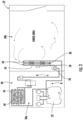
FIG. 2 , a basic refrigeration circuit of therefrigeration unit 30 is shown. Therefrigeration unit 30 is divided into two sections, acondenser section 30a and anevaporator section 30b. Thecondenser section 30a may disposed generally forward of a front wall of thecontainer 22 and is arranged in fluid communication with the ambient atmosphere external to thetrailer 22 and therefrigeration unit 30 to exchange air and heat therewith. Theevaporator section 30b is not in fluid communication with the ambient atmosphere to control temperature within thetrailer 22. Therefrigeration unit 30 includes acompressor 32, acondenser coil 34, anexpansion device 36, and anevaporator coil 38 fluidly connected to one another to form a closed loop system. A fluid R, such as a refrigerant for example, is configured to flow from thecompressor 32 to thecondenser coil 34,expansion device 36, andevaporator coil 38 in series. Acondenser fan 40, such as driven by a condenser motor (not shown) is configured to move a flow of air across an exterior of thecondenser coil 34, and anevaporator fan 42, such as driven by an evaporator motor (not shown), may be used to drive a flow of fluid (air) across an exterior of theevaporator coil 38. - In an embodiment, the refrigerant R circuiting within the
refrigeration unit 30 is an A2L refrigerant. The classification of refrigerant is based upon American Society of Heating, Refrigerating and Air-Conditioning (ASHRAE)Standard 34. The standard evaluates each refrigerant's flammability and toxicity and gives it a class referenced as a letter and number combination. The letter refers to the refrigerants' toxicity, and is based on the particular refrigerant's occupational exposure limit (OEL). The number adjacent to the letter refers to the refrigerant's flammability, and is based on the burning velocity (BV), heat of combustion (HOC), and lower flammability limits (LFL) of the particular refrigerant. - With continued reference to
FIG. 2 , the refrigerant R within the closed loop refrigerant circuit of therefrigeration unit 30 may, in rare instances, leak. When utilizing A2L refrigerants in therefrigeration unit 30, a leak of refrigerant R could lead to undesirable consequences due to the mildly flammable nature of A2L refrigerants. Accordingly, in an embodiment, therefrigeration unit 30 includes at least onerefrigerant detection assembly 50 operable to detect a refrigerant leak therein. For example, theevaporator section 30b includes at least onerefrigerant detection assembly 50. The at least onerefrigerant detection assembly 50 may be mounted to the evaporator housing of theevaporator coil 38 to detect gaseous refrigerant located external to at least onetube 44 of theevaporator coil 38. However, embodiments where arefrigerant detection assembly 50 is alternatively or additionally arranged at any suitable location relative to therefrigeration unit 30 or thecontainer 22 to detect a leak therein are also within the scope of the invention as set out in the appended claims. In an embodiment, therefrigerant detection assembly 50 enables the detection of leaks within ten seconds of being exposed to 100% lower flammability limit (LFL). In another embodiment, therefrigerant detection assembly 50 enables the detection of leaks within thirty seconds of being exposed to 25% lower flammability limit (LFL). A lower flammability limit (LFL) of a refrigerant is the minimum concentration limit that is required for the refrigerant to become potentially combustible. It is envisioned that therefrigerant detection assembly 50 described herein may be capable of detecting a leak of at least one A2L refrigerant when therefrigerant detection assembly 50 detects at least 5 to 50% LFL in the sample. - An example of a
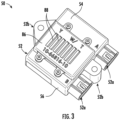
refrigerant detection assembly 50 is illustrated in more detail inFIGS. 3-4 . Therefrigerant detection assembly 50 includes ahousing 52. In the illustrated, non-limiting embodiment, therefrigerant detection assembly 50 is configured to mechanically integrate or couple torefrigerant unit 30 using the mountingholes 52b on thehousing 52. Further, therefrigerant detection assembly 50 may be configured to electrically integrate with therefrigerant unit 30 via theconnectors 52a on thehousing 52. As an example, the mountingholes 52b andconnectors 52a are formed as a continuous piece ofmaterial 52. - In the illustrated, non-limiting embodiment, the
housing 52 is formed from aseparate cover 54 andbase 56 that are generally complementary in size and shape. Thecover 54 andbase 56 may be formed from a durable material, such as plastic or resin for example. Thecover 54 may be removably coupled to thebase 56, such as via a plurality of fasteners, or alternatively, may be permanently affixed thereto. In an embodiment, thebase 56 has a bottom 58 and a plurality ofsidewalls 60 extending from the bottom 58 such that aninternal cavity 62 is defined between the bottom 58 and the plurality ofsidewalls 60. Accordingly, thecover 54 may be configured to couple to the distal end of the plurality ofsidewalls 60 to seal thecavity 62. However, it should be understood that embodiments where thecavity 62 is formed in thecover 54 and embodiments where thecavity 62 is defined by thecover 54 and the base 56 in combination are also contemplated herein. - A
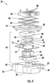
subassembly 64 may be installed within thecavity 62 of thehousing 52. Thesubassembly 64 includes ahousing 65 that defines an internal air chamber. In an embodiment, thehousing 65 is formed from a removably or a permanently coupledtop sensor cover 66 and a correspondingbottom sensor cover 68. At least one of thetop sensor cover 66 and thebottom sensor cover 68 has an opening orhole 70 formed therein. In the coupled configuration, the top and bottom sensor covers 66, 68 define anair chamber 72 therebetween, theair chamber 72 being fluidly connected with theopening 70. - Further, a sensor such as a non-dispersive infrared (NDIR) sensor for example, may be associated with the
air chamber 72. As is known in the art, a NDIR sensor is configured to use light, for example infrared light, to evaluate the absorption characteristics of gas molecules within the light path. The gas molecules are identified and the concentration of the gas molecules may be determined by utilizing the relation (Lambert-Beer law) between the gas concentration and the absorption intensity. In an embodiment, the NDIR sensor is configured to detect the presence of refrigerant molecules, such as an A2L refrigerant for example. Accordingly, when a leak is present, the sample within theair chamber 72 will contain a mixture of air and refrigerant. - A printed
circuit board 74 is disposed generally adjacent to a portion, such as the bottom surface for example, of thehousing 65. Although theair chamber 72 within thehousing 65 functions as a reflective cavity for the optical path of the sensor, the printedcircuit board 74 includes the circuitry and/or components associated with operation of the sensor. In an embodiment, the printedcircuit board 74 contains the infra-red light source (not shown) and at least one corresponding detector element (not shown). The printedcircuit board 74 may additionally include signal amplification and conditioning electronics. In an embodiment, the heat generated by the infra-red light source and/or the other electrical components of the printedcircuit board 74 may be sufficient to maintain the sensor at a temperature above ambient to prevent condensation and/or frosting. However, in other embodiments, the printedcircuit board 74 additionally includes one or more heating elements disposed throughout and adjacent to thehousing 65. - The printed
circuit board 74 may be directly connected to a power source, or alternatively, may be adapted to receive one or more batteries sufficient to provide power thereto to operate therefrigerant detection assembly 50 for an extended period of time. In such embodiments, the power provided by the batteries may be the sole source of power used to operate therefrigerant detection assembly 50 or alternatively, may be supplemental to the power source, for example in the event of a failure or loss of power at the power source. The printedcircuit board 74 is configured to form an interface between the sensor and theconnectors 52b to provide power and data to or from therefrigeration unit 30. - In an embodiment, a
heat conduction plate 76 is permanently or removably connected to the printedcircuit board 74 opposite thehousing 65. Theheat conduction plate 76 may be in direct contact with the one ormore heating elements 75 or may be indirectly coupled to saidheating elements 75. Theheat conduction plate 76 may be formed from a material having a high thermal conductivity, such as aluminum for example, to keep the sensor and/or the printedcircuit board 74 at a higher temperature relative to surroundings, thereby preventing condensation and frosting conditions. Theheat conduction plate 76 is additionally configured to shield the sensor/printedcircuit board 74 from electrical noise and emissions within the environment of thecontainer 22. Abreathable film 78, selectively permeable to certain elements, may be mounted in overlapping relationship with a portion of thehousing 65. In an embodiment, theopening 70 is formed in an upper surface of thetop sensor cover 66, and thebreathable film 78 is in direct contact with and overlaps the upper surface of thetop sensor cover 66. By positioning thebreathable film 78 over theopening 70, gasses are able to permeate through thefilm 78 into theair chamber 72, but contaminants such as dust, oil droplets and moisture in the form of liquid are prevented from entering theair chamber 72 and from damaging the printedcircuit board 74. - The subassembly formed by the
housing 65, printedcircuit board 74, andheat conduction plate 76 is receivable within thecavity 62 of thehousing 52. At least oneinsulator 80 may be used to position or mount the subassembly within thecavity 62. Examples of suitable materials for the insulator(s) 80 include but are not limited to Styrofoam and rubber. In an embodiment, at least onefirst insulator 80 is arranged between the distal end of theheat conduction plate 76 and an interior surface of thebase 56. Alternatively, or in addition, at least onesecond insulator 80 may be arranged adjacent to the top of thehousing 65. Inclusion of the one ormore insulators 80 is intended to restrict movement of the subassembly within thecavity 62, dampen any vibrations that may be transferred to the subassembly, and further enhance the weatherproof seal of the subassembly. Theinsulators 80 may additionally prevent heat loss from the electronics embedded within the printedcircuit board 74,active heating elements 75 andheat conduction plate 76. - As shown, an
insulator 80 may have agroove 82 formed in a surface thereof, thegroove 82 being complementary to the adjacent portion of the subassembly. For example, theinsulator 80 positioned adjacent to thebase 56 of thehousing 52 has agroove 82 complementary in size and shape to theheat conduction plate 76 such that the adjacent portion of theheat conduction plate 76 is seated within thegroove 82. Furthermore, aninsulator 80 may contain additional groves for accommodating the one ormore heating elements 75. Similarly, theinsulator 80 positioned adjacent to thecover 54 of thehousing 52 may have a groove complementary to thetop sensor cover 66, such that thetop sensor cover 66 is at least partially received within the groove. Theinsulators 80 illustrated and described herein are intended as an example only and it should be understood that the use of more than oneinsulator 80 at each of the positions described herein, as well as the inclusion of one ormore insulators 80 at other locations about the subassembly are within the scope of the invention as set out in the appended claims. - The
cover 54 of thehousing 52 has anopening 84 formed therein to define a flow path between the opening and thecavity 62. As a result, the ambient atmosphere or air surrounding therefrigerant detection assembly 50 is configured to flow through theopening 84, into theinternal cavity 62 and into theair chamber 72. In an embodiment, a secondary cover orshell 86 is connectable to thecover 54 of thehousing 52. Theshell 86 is positionable in overlapping arrangement with theopening 84 and may be permanently or removably affixed to thecover 54, such as with a plurality of fasteners for example. Similar to thecover 54, theshell 86 has ashell opening 88 formed therein, theshell opening 88 being arranged in fluid communication with theopening 84 in thecover 54. In the illustrated, non-limiting embodiment, theshell 86 has a plurality of substantiallyidentical shell openings 88 aligned to form a grill. To further protect the subassembly from damage and contamination, abreathable film 90 and/or an insulator, also referred to herein as ashell insulator 92, may be arranged between the exterior of thecover 54 and a portion of theshell 86. In an embodiment, thebreathable film 90 is replaceable. - The
refrigerant detection assembly 50 components are combined to enable environmental robustness. The printedcircuit board 74,breathable films insulator 80 andshell openings 88 may be designed such that in combination these features reduce the impact of moisture on operation of the sensor or detection of refrigerant by limiting water intrusion and reducing condensation buildup. Furthermore, theportions housing 52, theinternal housing 65, theshell 86, theheat conduction plate 76, and the one ormore insulators 80 may be configured to remove condensation when present and/or may be integrated to enable mechanical robustness while allowing fluid connection with therefrigeration unit 30. - The term "about" is intended to include the degree of error associated with measurement of the particular quantity based upon the equipment available at the priority date of the application.
- The terminology used herein is for the purpose of describing particular embodiments only and is not intended to be limiting of the present disclosure. As used herein, the singular forms "a", "an" and "the" are intended to include the plural forms as well, unless the context clearly indicates otherwise. It will be further understood that the terms "comprises" and/or "comprising," when used in this specification, specify the presence of stated features, integers, steps, operations, elements, and/or components, but do not preclude the presence or addition of one or more other features, integers, steps, operations, element components, and/or groups thereof.
- While the present disclosure has been described with reference to an exemplary embodiment or embodiments, it will be understood by those skilled in the art that various changes may be made and equivalents may be substituted for elements thereof without departing from the scope of the present invention as set out in the appended claims. In addition, many modifications may be made to adapt a particular situation or material to the teachings of the present invention without departing from the essential scope thereof. Therefore, it is intended that the present invention not be limited to the particular embodiment disclosed as the best mode contemplated for carrying out this present invention, but that the present invention will include all embodiments falling within the scope of the claims.
Claims (15)
- A refrigerant detection assembly (50) operable to detect refrigerant mixed with air, the refrigerant detection assembly (50) comprising:a housing (52) having an internal cavity (62) fluidly connected with an ambient atmosphere surrounding the housing (52) via an opening (84);a subassembly (64) mounted within the internal cavity (62), the subassembly (64) comprising:an air chamber (72), the air chamber (72) being fluidly connected with the internal cavity (62);(72); a non-dispersive infrared sensor operably coupled to the air chambera printed circuit board (74) operably coupled to the non-dispersive infrared sensor; anda heat conduction plate (76) mechanically and thermally coupled to the printed circuit board (74);at least one insulator (80, 92) arranged within the internal cavity (62) at a position between a portion of the subassembly (64) and the housing (52); anda shell (86) connectable to the housing (52) in overlapping arrangement with the opening (84), the shell (86) having at least one shell opening (88) formed therein such that a flow path extends from the shell opening (88), through the opening (84) formed in the housing (52) to the internal cavity (62), and into the air chamber (72).
- The refrigerant detection assembly (50) of claim 1, wherein the non-dispersive infrared sensor includes a light source and a detector element, the light source and the detector element being mounted to the printed circuit board (74).
- The refrigerant detection assembly (50) of claim 1 or 2, wherein the air chamber (72) is positioned adjacent to a first side of the printed circuit board (74), and the heat conduction plate (76) is arranged adjacent to a second, opposite side of the printed circuit board (74).
- The refrigerant detection assembly (50) of claim 1, 2 or 3, wherein the subassembly (64) further comprises at least one active heating element (75) operably coupled to the non-dispersive infrared sensor.
- The refrigerant detection assembly of any preceding claim, wherein the air chamber (72) is defined between a top sensor cover (66) and a bottom sensor cover (68) and at least one of the top sensor cover (66) and the bottom sensor cover (68) has a hole (70) formed therein, the subassembly further comprising a film (78) disposed in overlapping arrangement with the hole (70), wherein the film (78) is permeable to gas and impermeable to liquid.
- The refrigerant detection assembly (50) of any preceding claim, further comprising a film (90) disposed in overlapping arrangement with the opening (84), wherein the film (90) is permeable to gas and impermeable to liquid.
- The refrigerant detection assembly (50) of any preceding claim, wherein the housing (52) further comprises a cover (54) and a bottom (56), and the at least one insulator (80, 92) further comprises a first insulator disposed between the subassembly (64) and the cover (54) and a second insulator positioned between the subassembly (64) and the cover (54), optionally:
wherein at least one of the first insulator and the second insulator has a groove (82) complementary to a corresponding portion of the subassembly (64) receivable therein. - The refrigerant detection assembly (50) of any preceding claim, wherein the at least one insulator (92) further comprises a shell insulator (92) positioned between the shell (86) and the housing (52).
- A refrigerated container system (20) comprising:a refrigeration system (30) including a closed loop refrigerant circuit having a refrigerant (R) circulating therein; anda container (22) having a cargo area arranged in fluid communication with the refrigeration system (30); anda refrigerant detection assembly (50) operable to detect refrigerant from the closed loop refrigerant circuit mixed with air, the refrigerant detection assembly (50) comprising:a housing (52) having an internal cavity (62) and an opening (84) such that a flow path extends from the opening into the internal cavity (62);a subassembly (64) arranged within the internal cavity (62), the subassembly (64) including:an air chamber (72) fluidly connected to the internal cavity (62);a non-dispersive infrared sensor operably coupled to the air chamber (72);a printed circuit board (74) operably coupled to the non-dispersive infrared sensor; anda heat conduction plate (76) thermally coupled to the printed circuit board (74); andat least one insulator (80, 92) for mounting the subassembly (64) within the internal cavity (62).
- The refrigerated container system (20) of claim 9, wherein the refrigeration system (30) includes an evaporator coil (38) and the refrigerant detection assembly (50) is mounted adjacent to the evaporator coil (38), optionally:
wherein the evaporator coil (38) includes at least one tube (44) arranged within an evaporator housing, and the refrigerant detection assembly (50) is mounted to the evaporator housing. - The refrigerated container system (20) of claim 9 or 10, wherein the container (22) is a cargo container transportable by a watercraft.
- The refrigerated container system (20) of any of claims 9 to 11, wherein the refrigerant detection assembly (50) is operable to detect a leak within the closed loop refrigerant circuit within ten seconds of being exposed to 100% of a lower flammability limit; and/or
wherein the refrigerant detection assembly (50) is operable to detect a leak within the closed loop refrigerant circuit when the refrigerant (R) measured by the non-dispersive infrared sensor is at least 25% of a lower flammability limit. - The refrigerated container system (20) of any of claims 9 to 12, wherein the non-dispersive infrared sensor is integrally formed with the printed circuit board (74).
- The refrigerated container system (20) of any of claims 9 to 13, wherein the subassembly (64) further comprises at least one active heating element (75) operably coupled to the non-dispersive infrared sensor; and/or
wherein the air chamber (72) is defined between a top sensor cover (66) and a bottom sensor cover (68) and at least one of the top sensor cover (66) and the bottom sensor cover (68) has a hole (70) formed therein, the subassembly (64) further comprising a film (78) disposed in overlapping arrangement with the hole (70), wherein the film is permeable to gas and impermeable to liquid. - The refrigerated container system (20) of any of claims 9 to 14, wherein the refrigerant detection assembly (50) further comprises a shell (86) connectable to the housing (52) in overlapping arrangement with the opening (84), the shell (86) having at least one shell opening (88) formed therein such that a flow path extends from the shell opening (88), through the opening (84) formed in the housing to the internal cavity (62), and into the air chamber (72), optionally:
further comprising:at least one shell insulator (92) positioned between the shell (86) and the housing (52); anda film (90) disposed in overlapping arrangement with the opening (84), the film being permeable to gas and impermeable to liquid.
Applications Claiming Priority (1)
| Application Number | Priority Date | Filing Date | Title |
|---|---|---|---|
| US202163250391P | 2021-09-30 | 2021-09-30 |
Publications (1)
| Publication Number | Publication Date |
|---|---|
| EP4160187A1 true EP4160187A1 (en) | 2023-04-05 |
Family
ID=83546864
Family Applications (1)
| Application Number | Title | Priority Date | Filing Date |
|---|---|---|---|
| EP22199212.6A Pending EP4160187A1 (en) | 2021-09-30 | 2022-09-30 | Environmental enclosure for a gas sensor for use in a transport vehicle |
Country Status (4)
| Country | Link |
|---|---|
| US (1) | US12253457B2 (en) |
| EP (1) | EP4160187A1 (en) |
| JP (1) | JP2023051831A (en) |
| CN (1) | CN115901619A (en) |
Cited By (3)
| Publication number | Priority date | Publication date | Assignee | Title |
|---|---|---|---|---|
| USD1115570S1 (en) | 2023-08-15 | 2026-03-03 | Danfoss A/S | Gas detection sensor |
| USD1115569S1 (en) | 2022-11-28 | 2026-03-03 | Danfoss A/S | Gas detection sensor |
| USD1119637S1 (en) | 2023-02-09 | 2026-03-24 | Danfoss A/S | Gas detection sensor |
Families Citing this family (8)
| Publication number | Priority date | Publication date | Assignee | Title |
|---|---|---|---|---|
| US10119738B2 (en) | 2014-09-26 | 2018-11-06 | Waterfurnace International Inc. | Air conditioning system with vapor injection compressor |
| US10871314B2 (en) | 2016-07-08 | 2020-12-22 | Climate Master, Inc. | Heat pump and water heater |
| US10866002B2 (en) | 2016-11-09 | 2020-12-15 | Climate Master, Inc. | Hybrid heat pump with improved dehumidification |
| US11592215B2 (en) | 2018-08-29 | 2023-02-28 | Waterfurnace International, Inc. | Integrated demand water heating using a capacity modulated heat pump with desuperheater |
| CA3081986A1 (en) | 2019-07-15 | 2021-01-15 | Climate Master, Inc. | Air conditioning system with capacity control and controlled hot water generation |
| US12181189B2 (en) | 2021-11-10 | 2024-12-31 | Climate Master, Inc. | Ceiling-mountable heat pump system |
| US12492968B2 (en) | 2022-07-12 | 2025-12-09 | Cteh, Llc | Climate controlled housing for instrumentation |
| US12460832B2 (en) * | 2023-01-18 | 2025-11-04 | Lennox Industries Inc. | Refrigerant detection for a cooling system |
Citations (6)
| Publication number | Priority date | Publication date | Assignee | Title |
|---|---|---|---|---|
| US5834777A (en) * | 1994-02-14 | 1998-11-10 | Telaire Systems, Inc. | NDIR gas sensor |
| JP2006266769A (en) * | 2005-03-23 | 2006-10-05 | Riken Keiki Co Ltd | Reflective infrared gas detector |
| CN201110830Y (en) * | 2007-12-14 | 2008-09-03 | 煤炭科学研究总院重庆研究院 | Non-dispersive infrared methane sensor for coal mine |
| CN103674883A (en) * | 2013-12-20 | 2014-03-26 | 中国科学技术大学 | Micro intermediate infrared gas concentration monitoring method and device |
| EP3748260A1 (en) * | 2019-06-05 | 2020-12-09 | Carrier Corporation | Enclosure for gas detector |
| CN113015641A (en) * | 2019-09-18 | 2021-06-22 | 开利公司 | Heated gas detector |
Family Cites Families (116)
| Publication number | Priority date | Publication date | Assignee | Title |
|---|---|---|---|---|
| US3455792A (en) | 1966-05-12 | 1969-07-15 | Daikin Ind Ltd | Removal of liquid particles during distillation from gases with porous polytetrafluoroethylene paper |
| US4947548A (en) | 1985-09-20 | 1990-08-14 | Carrier Corporation | Method of making a heat exchanger for condensing furnace |
| USD320212S (en) | 1989-04-11 | 1991-09-24 | Ricoh Company, Ltd. | Adapter for telephone data communication equipment |
| JPH0360710A (en) | 1989-07-28 | 1991-03-15 | Sumitomo Chem Co Ltd | Filter medium for purifying air |
| JPH0360711A (en) | 1989-07-28 | 1991-03-15 | Sumitomo Chem Co Ltd | Filter medium for purifying air |
| USD329639S (en) | 1990-03-26 | 1992-09-22 | International Business Machines Corporation | Optoelectronic assembly |
| JP3164159B2 (en) | 1991-05-31 | 2001-05-08 | 東洋紡績株式会社 | Electret air filter for removing sea salt particles |
| US5623105A (en) | 1992-10-21 | 1997-04-22 | Prolong Systems, Inc. | Oxygen/carbon dioxide sensor and controller for a refrigerated controlled atmosphere shipping container |
| JP3114079B2 (en) | 1992-12-22 | 2000-12-04 | 金井 宏之 | Filter material made of non-woven fabric for removing salt and air filter using the same |
| USD376549S (en) | 1995-05-06 | 1996-12-17 | J. Lorch Ges. & Co. Gmbh | Air compressor maintenance device |
| USD389808S (en) | 1996-01-09 | 1998-01-27 | Fuji Electric Co., Ltd. | Hybrid integrated circuit for electric power control |
| US5886348A (en) * | 1997-02-14 | 1999-03-23 | American Intell-Sensors Corporation | Non-dispersive infrared gas analyzer with interfering gas correction |
| JP4640895B2 (en) | 2001-03-29 | 2011-03-02 | 日本無機株式会社 | High performance filter for gas turbine intake and gas turbine intake filter unit using the same |
| USD462054S1 (en) | 2001-09-05 | 2002-08-27 | Hon Hai Precision Ind. Co., Ltd. | Electrical connector |
| JP3924202B2 (en) | 2002-05-24 | 2007-06-06 | 日本特殊陶業株式会社 | Gas sensor |
| USD488815S1 (en) | 2002-10-25 | 2004-04-20 | Yamaichi Electronics Co., Ltd. | Card connector |
| USD496905S1 (en) | 2002-12-13 | 2004-10-05 | Delta Electronics Inc. | Filter module |
| USD494933S1 (en) | 2002-12-19 | 2004-08-24 | K.S. Terminals Inc. | Electricity connector |
| USD533832S1 (en) | 2005-06-15 | 2006-12-19 | Nilar International Ab | Battery casing |
| GB0602320D0 (en) | 2006-02-06 | 2006-03-15 | Gas Sensing Solutions Ltd | Domed gas sensor |
| USD577674S1 (en) | 2007-01-17 | 2008-09-30 | Hon Hai Precision Ind. Co., Ltd | Electrical connector |
| EP1965217B1 (en) | 2007-03-02 | 2012-08-29 | Liaisons Electroniques-Mecaniques Lem S.A. | High bandwidth open-loop current sensor |
| ES2662074T3 (en) | 2009-07-08 | 2018-04-05 | Daikin Industries, Ltd. | Ventilation system |
| USD668978S1 (en) | 2010-03-01 | 2012-10-16 | Yazaki Corporation | Current sensor |
| JP5975596B2 (en) | 2010-08-05 | 2016-08-23 | 矢崎総業株式会社 | Current sensor structure |
| USD689446S1 (en) | 2010-10-28 | 2013-09-10 | Fuji Electric Co., Ltd. | Semiconductor |
| USD653634S1 (en) | 2010-10-28 | 2012-02-07 | Fuji Electric Co., Ltd. | Semiconductor |
| USD653633S1 (en) | 2010-12-14 | 2012-02-07 | Fuji Electric Co., Ltd. | Semiconductor |
| CN102198358A (en) | 2011-05-25 | 2011-09-28 | 国电联合动力技术有限公司 | Salt mist filtering ventilation device for engine room of maritime or offshore wind driven generator |
| ITTV20110073A1 (en) | 2011-05-30 | 2012-12-01 | Texa Spa | GAS ANALYZER SYSTEM CONFIGURED TO DETERMINE THE CONCENTRATION OF A REFRIGERANT GAS AND / OR OF CONTAMINATING GAS PRESENT IN A SELF-MULTI-AIR AIR CONDITIONING SYSTEM |
| USD662889S1 (en) | 2011-08-03 | 2012-07-03 | Anderson Power Products, Inc. | Polarized 3 pole electrical connector with protective ground |
| USD660243S1 (en) | 2011-08-03 | 2012-05-22 | Anderson Power Products, Inc. | Polarized 3 pole electrical connector with protective ground |
| USD660241S1 (en) | 2011-08-03 | 2012-05-22 | Anderson Power Products, Inc. | Polarized 3 pole electrical connector with protective ground |
| USD686174S1 (en) | 2011-08-12 | 2013-07-16 | Fuji Electric Co., Ltd | Semiconductor device |
| EP2840115B1 (en) | 2012-04-20 | 2018-06-06 | Daikin Industries, Ltd. | Composition mainly composed of ptfe, mixed powder, molding material, filtering medium for filter, air filter unit, and porous membrane manufacturing method |
| KR101203120B1 (en) | 2012-04-26 | 2012-11-21 | (주) 성일 | Coating Solution for salt damage protection and salt damage protection filter and salt damage protection filter membrane thereof |
| USD702242S1 (en) | 2012-08-22 | 2014-04-08 | Yokogawa Electric Corporation | Signal conversion module for recorder |
| USD727758S1 (en) | 2013-08-09 | 2015-04-28 | Spireon, Inc. | Mediation device |
| WO2015027183A1 (en) | 2013-08-23 | 2015-02-26 | American Air Filter Company, Inc. | Prefilter wrap |
| EP3036028B1 (en) | 2013-08-23 | 2022-03-02 | American Air Filter Company, Inc. | Canister filter with prefiltration |
| USD718717S1 (en) | 2013-08-28 | 2014-12-02 | River of Goods, Inc. | Battery box |
| USD728398S1 (en) | 2013-08-28 | 2015-05-05 | Japan Aviation Electronics Industry, Limited | Current sensor |
| CN104566707A (en) | 2013-10-23 | 2015-04-29 | 江苏永昇空调有限公司 | Air conditioner for port crane driver control room |
| US10245545B2 (en) | 2013-10-23 | 2019-04-02 | Daikin Industries, Ltd. | Embossed air filter filtration medium, filter pack, air filter unit, and method for manufacturing filtration medium for embossed air filter |
| US9804084B2 (en) | 2013-11-11 | 2017-10-31 | Amphenol Thermometrics, Inc. | Optical gas sensor |
| JP5835389B2 (en) | 2014-03-26 | 2015-12-24 | ダイキン工業株式会社 | Air filter medium, filter pack, air filter unit, and method of manufacturing air filter medium |
| US10075001B2 (en) | 2014-06-03 | 2018-09-11 | Traxxas, LP | Battery connection method and apparatus |
| USD743339S1 (en) | 2014-07-22 | 2015-11-17 | Traxxas Lp | Female electrical connector |
| US10416113B2 (en) | 2014-08-20 | 2019-09-17 | Carrier Corporation | Detection of refrigerant contaminants |
| CN104280358B (en) | 2014-09-05 | 2017-11-21 | 汉威科技集团股份有限公司 | Miniature infrared gas sensor |
| US9683686B2 (en) | 2014-12-15 | 2017-06-20 | American Air Filter Company, Inc. | Auto-draining filter apparatus |
| US10488065B2 (en) | 2014-12-17 | 2019-11-26 | Carrier Corporation | Leak detection unit for refrigerant system |
| USD743341S1 (en) | 2014-12-23 | 2015-11-17 | General Electric Company | Busbar chopper module |
| CN104677851B (en) | 2015-02-17 | 2018-02-13 | 苏州诺联芯电子科技有限公司 | gas sensor and preparation method thereof |
| JP6466219B2 (en) | 2015-03-20 | 2019-02-06 | 日立ジョンソンコントロールズ空調株式会社 | Air conditioner indoor unit |
| KR102314047B1 (en) | 2015-04-27 | 2021-10-18 | 삼성에스디아이 주식회사 | Battery module |
| ES2786301T3 (en) | 2015-06-24 | 2020-10-09 | Aaf Ltd | System to reduce the inlet air temperature of a device |
| TWD179620S (en) | 2015-07-16 | 2016-11-21 | 戴健郎 | Battery cover part |
| CN205262956U (en) | 2015-09-10 | 2016-05-25 | 上海申渭电子科技有限公司 | Infrared SF6 sensor device of relevant NDIR |
| US20180327179A1 (en) | 2015-11-09 | 2018-11-15 | Carrier Corporation | Refrigerated Transport System with Refrigerant Dilution |
| CN108351129A (en) * | 2015-11-09 | 2018-07-31 | 开利公司 | Series loop intermodal container |
| CN106150783B (en) | 2016-08-25 | 2019-02-15 | 哈尔滨恒通排水设备制造股份有限公司 | A kind of compound filter |
| CN206402569U (en) | 2016-12-12 | 2017-08-11 | 中国人民解放军63810部队 | A kind of anti salt spray corrosion electric appliance box |
| JP6673230B2 (en) | 2017-01-12 | 2020-03-25 | ダイキン工業株式会社 | Air filter media |
| US10703341B2 (en) | 2017-02-03 | 2020-07-07 | Magna Electronics Inc. | Vehicle sensor housing with theft protection |
| CN206476084U (en) | 2017-02-23 | 2017-09-08 | 合肥迅驰电子科技有限责任公司 | A kind of protection type marine air conditioner controller |
| USD884598S1 (en) | 2017-03-10 | 2020-05-19 | Kabushiki Kaisha Toshiba | Battery module |
| USD887968S1 (en) | 2017-03-10 | 2020-06-23 | Kabushiki Kaisha Toshiba | Battery module |
| JP6658687B2 (en) | 2017-07-10 | 2020-03-04 | ダイキン工業株式会社 | Indoor unit of an air conditioner having a refrigerant detection sensor |
| CN207035593U (en) | 2017-07-18 | 2018-02-23 | 泰豪科技股份有限公司 | Islands and reefs type cooling by wind and cooling system |
| CN107314583A (en) | 2017-07-18 | 2017-11-03 | 泰豪科技股份有限公司 | Islands and reefs type cooling by wind and cooling technique |
| CN109284512B (en) | 2017-07-20 | 2023-12-26 | 开利公司 | Implementing optical fiber high sensitivity smoke detector system using building information model |
| EP3647694B1 (en) | 2017-07-21 | 2026-02-18 | Daikin Industries, Ltd. | Gas supply device, device for controlling air inside vehicle, and refrigeration device for container |
| DK3667213T3 (en) | 2017-09-19 | 2022-07-04 | Daikin Ind Ltd | AIR SUPPLY DEVICE, ADJUSTMENT DEVICE FOR AN INTERNAL ROOM AND CONTAINER COOLING DEVICE |
| JP6590058B2 (en) | 2017-09-29 | 2019-10-16 | ダイキン工業株式会社 | Air composition controller |
| JP6665909B2 (en) | 2017-09-29 | 2020-03-13 | ダイキン工業株式会社 | Cabin air conditioner |
| SG11202002861QA (en) | 2017-09-29 | 2020-04-29 | Daikin Ind Ltd | Internal air adjustment device |
| JP6890188B2 (en) | 2017-11-15 | 2021-06-18 | 日立ジョンソンコントロールズ空調株式会社 | Air conditioner |
| KR101895236B1 (en) | 2017-12-22 | 2018-09-07 | 주식회사 이엘티센서 | Optical cavity for gas sensor and gas sensor having the same |
| CN108593532A (en) | 2018-04-26 | 2018-09-28 | 武汉博富通试验设备有限公司 | A kind of salt fog/acid mist chamber filtration system |
| WO2019216312A1 (en) | 2018-05-07 | 2019-11-14 | ダイキン工業株式会社 | Humidifier and air composition adjustment device |
| CN208778103U (en) | 2018-05-09 | 2019-04-23 | 株洲航发动科南方燃气轮机有限公司 | Air intake filter |
| US11435102B2 (en) | 2018-05-10 | 2022-09-06 | Mitsubishi Electric Corporation | Refrigerant leakage determination device, air-conditioning apparatus, and refrigerant leakage determination method |
| USD929462S1 (en) | 2018-06-04 | 2021-08-31 | Semikron Elektronik Gmbh & Co. Kg | Module |
| WO2020001471A1 (en) | 2018-06-26 | 2020-01-02 | 浙江三花智能控制股份有限公司 | Infrared sensor and infrared gas detector |
| CN108593587A (en) | 2018-07-03 | 2018-09-28 | 青岛海纳光电环保有限公司 | A kind of non-dispersion infrared gas sensor |
| EP3850282B1 (en) | 2018-09-12 | 2024-03-13 | Carrier Corporation | Refrigerant leak detection system |
| EP3858456A4 (en) | 2018-09-28 | 2022-07-20 | Daikin Industries, Ltd. | AIR FILTER FILTER MEDIA, FILTER CARTRIDGE, AIR FILTER UNIT, AND METHODS OF MAKING THE SAME |
| CN109507140B (en) | 2018-10-16 | 2020-04-10 | 四方光电股份有限公司 | High-precision infrared gas sensor and gas analysis method |
| CN209069825U (en) | 2018-10-30 | 2019-07-05 | 安徽六维传感科技有限公司 | A kind of binary channels infrared gas sensor |
| JP6687091B1 (en) | 2018-11-14 | 2020-04-22 | ダイキン工業株式会社 | Inside air conditioner |
| USD890095S1 (en) | 2018-11-30 | 2020-07-14 | Guangdong Gopod Group Holding Co., Ltd. | Multi-function converter |
| US11183440B2 (en) | 2018-12-10 | 2021-11-23 | Gan Systems Inc. | Power modules for ultra-fast wide-bandgap power switching devices |
| USD895549S1 (en) | 2018-12-18 | 2020-09-08 | Ademco Inc. | Heat pump controller |
| CN109733229A (en) | 2018-12-26 | 2019-05-10 | 王建华 | Harbour salt spray proof automatic transportation equipment charging pile |
| US11096301B2 (en) | 2019-01-03 | 2021-08-17 | Magna Electronics Inc. | Vehicular radar sensor with mechanical coupling of sensor housing |
| JP1646778S (en) | 2019-02-07 | 2019-12-02 | ||
| CN209802977U (en) | 2019-03-29 | 2019-12-17 | 南京信息工程大学 | A multi-component infrared gas detection device based on a box-like reflective gas chamber |
| USD903611S1 (en) | 2019-03-29 | 2020-12-01 | Mitsubishi Electric Corporation | Semiconductor device |
| CN210196149U (en) | 2019-04-12 | 2020-03-27 | 深圳华盛过滤系统有限公司 | Air inlet system of gas turbine machine room |
| FR3096461B1 (en) | 2019-05-23 | 2021-10-29 | Elichens | Device for emitting and controlling infrared light and gas sensor using such a device |
| JP7079226B2 (en) | 2019-07-12 | 2022-06-01 | ダイキン工業株式会社 | Refrigerant cycle system equipped with a refrigerant leak notification device and a refrigerant leakage notification device |
| CN110907385A (en) | 2019-12-10 | 2020-03-24 | 江苏物联网研究发展中心 | NDIR infrared gas sensor |
| CN212454698U (en) | 2020-02-21 | 2021-02-02 | 长江三峡集团福建能源投资有限公司 | Fresh air salt mist removing system of module pre-installed type offshore booster station |
| CN111219302A (en) | 2020-02-21 | 2020-06-02 | 长江三峡集团福建能源投资有限公司 | Fresh air salt mist removing system of module pre-installed type offshore booster station |
| CN212290294U (en) | 2020-04-02 | 2021-01-05 | 澳龙船艇科技有限公司 | Marine ventilation filter equipment |
| CN111644003B (en) | 2020-04-22 | 2021-05-07 | 中国电器科学研究院股份有限公司 | Long-term maintenance-free salt spray filtration system and control method |
| CN213556026U (en) | 2020-07-13 | 2021-06-29 | 杭州彩贝化工有限公司 | Salt mist processor |
| CN212568464U (en) | 2020-09-09 | 2021-02-19 | 成都凯能光电科技有限公司 | Infrared gas sensor based on NDIR technology |
| CN111879719A (en) | 2020-09-09 | 2020-11-03 | 成都凯能光电科技有限公司 | Infrared gas sensor based on NDIR technology |
| CN214038815U (en) | 2020-12-21 | 2021-08-24 | 四川死海极净呼吸环境科技有限公司 | Salt aerosol air purification all-in-one machine |
| CN113007863A (en) | 2021-02-19 | 2021-06-22 | 格力电器(合肥)有限公司 | Refrigerant leakage alarm sensor assembly, refrigeration equipment and alarm method |
| CN214757262U (en) | 2021-04-08 | 2021-11-16 | 上海勘测设计研究院有限公司 | De-salt mist air-conditioning system for marine containerized electrical cabins |
| CN113507824A (en) | 2021-07-23 | 2021-10-15 | 山东润扬环保设备有限公司 | Control cabinet desalination cooling system device for marine environment |
| USD1027682S1 (en) | 2021-09-30 | 2024-05-21 | Carrier Corporation | Refrigerant detection sensor housing |
| US12379308B2 (en) * | 2021-09-30 | 2025-08-05 | Carrier Corporation | Environmental enclosure for a transport gas sensor |
-
2022
- 2022-09-21 US US17/949,772 patent/US12253457B2/en active Active
- 2022-09-28 JP JP2022154399A patent/JP2023051831A/en active Pending
- 2022-09-29 CN CN202211195184.2A patent/CN115901619A/en active Pending
- 2022-09-30 EP EP22199212.6A patent/EP4160187A1/en active Pending
Patent Citations (6)
| Publication number | Priority date | Publication date | Assignee | Title |
|---|---|---|---|---|
| US5834777A (en) * | 1994-02-14 | 1998-11-10 | Telaire Systems, Inc. | NDIR gas sensor |
| JP2006266769A (en) * | 2005-03-23 | 2006-10-05 | Riken Keiki Co Ltd | Reflective infrared gas detector |
| CN201110830Y (en) * | 2007-12-14 | 2008-09-03 | 煤炭科学研究总院重庆研究院 | Non-dispersive infrared methane sensor for coal mine |
| CN103674883A (en) * | 2013-12-20 | 2014-03-26 | 中国科学技术大学 | Micro intermediate infrared gas concentration monitoring method and device |
| EP3748260A1 (en) * | 2019-06-05 | 2020-12-09 | Carrier Corporation | Enclosure for gas detector |
| CN113015641A (en) * | 2019-09-18 | 2021-06-22 | 开利公司 | Heated gas detector |
Cited By (3)
| Publication number | Priority date | Publication date | Assignee | Title |
|---|---|---|---|---|
| USD1115569S1 (en) | 2022-11-28 | 2026-03-03 | Danfoss A/S | Gas detection sensor |
| USD1119637S1 (en) | 2023-02-09 | 2026-03-24 | Danfoss A/S | Gas detection sensor |
| USD1115570S1 (en) | 2023-08-15 | 2026-03-03 | Danfoss A/S | Gas detection sensor |
Also Published As
| Publication number | Publication date |
|---|---|
| JP2023051831A (en) | 2023-04-11 |
| US20230094980A1 (en) | 2023-03-30 |
| CN115901619A (en) | 2023-04-04 |
| US12253457B2 (en) | 2025-03-18 |
Similar Documents
| Publication | Publication Date | Title |
|---|---|---|
| US12253457B2 (en) | Environmental enclosure for a transport gas sensor | |
| US12379308B2 (en) | Environmental enclosure for a transport gas sensor | |
| US11827080B2 (en) | Heated gas detector | |
| CN113758889B (en) | Enclosure for gas detectors | |
| CN110226073B (en) | refrigeration unit | |
| CN107182185B (en) | Cooling system for vehicle sensor module | |
| EP3374703B1 (en) | Series loop intermodal container | |
| EP1337825B1 (en) | Apparatus and method for diagnosing performance of air-conditioning systems | |
| US12276575B2 (en) | Sensor assembly and refrigerant sensing system | |
| WO2007131355A1 (en) | Temperature controlled container | |
| US20050120728A1 (en) | Supplemental heat control apparatus and method for freezer/refrigeration equipment | |
| US12241810B2 (en) | Sensor assembly | |
| US20080014854A1 (en) | Air conditioning system, method, and apparatus | |
| CN117213735A (en) | Refrigerant gas sensor | |
| JP2017067393A (en) | Freezer | |
| KR101491654B1 (en) | Advertising device for vehicle | |
| US20240060846A1 (en) | Gas sensor and method for detecting gas | |
| US10292251B2 (en) | X-ray inspection device | |
| US20260023061A1 (en) | Gas Sensor Assembly And Method For Detecting An Obstruction Thereof | |
| CN219245503U (en) | High-efficient accuse temperature's carbon dioxide analysis appearance | |
| WO2025237512A1 (en) | Detection device | |
| CN1993590A (en) | refrigerator |
Legal Events
| Date | Code | Title | Description |
|---|---|---|---|
| PUAI | Public reference made under article 153(3) epc to a published international application that has entered the european phase |
Free format text: ORIGINAL CODE: 0009012 |
|
| STAA | Information on the status of an ep patent application or granted ep patent |
Free format text: STATUS: THE APPLICATION HAS BEEN PUBLISHED |
|
| AK | Designated contracting states |
Kind code of ref document: A1 Designated state(s): AL AT BE BG CH CY CZ DE DK EE ES FI FR GB GR HR HU IE IS IT LI LT LU LV MC MK MT NL NO PL PT RO RS SE SI SK SM TR |
|
| P01 | Opt-out of the competence of the unified patent court (upc) registered |
Effective date: 20230527 |
|
| STAA | Information on the status of an ep patent application or granted ep patent |
Free format text: STATUS: REQUEST FOR EXAMINATION WAS MADE |
|
| 17P | Request for examination filed |
Effective date: 20231005 |
|
| RBV | Designated contracting states (corrected) |
Designated state(s): AL AT BE BG CH CY CZ DE DK EE ES FI FR GB GR HR HU IE IS IT LI LT LU LV MC MK MT NL NO PL PT RO RS SE SI SK SM TR |
|
| STAA | Information on the status of an ep patent application or granted ep patent |
Free format text: STATUS: EXAMINATION IS IN PROGRESS |
|
| 17Q | First examination report despatched |
Effective date: 20250319 |