EP4160068A1 - Electronic expansion valve, refrigerant circulation pipeline, and air conditioner system - Google Patents
Electronic expansion valve, refrigerant circulation pipeline, and air conditioner system Download PDFInfo
- Publication number
- EP4160068A1 EP4160068A1 EP21868250.8A EP21868250A EP4160068A1 EP 4160068 A1 EP4160068 A1 EP 4160068A1 EP 21868250 A EP21868250 A EP 21868250A EP 4160068 A1 EP4160068 A1 EP 4160068A1
- Authority
- EP
- European Patent Office
- Prior art keywords
- valve
- hole section
- electronic expansion
- section
- main
- Prior art date
- Legal status (The legal status is an assumption and is not a legal conclusion. Google has not performed a legal analysis and makes no representation as to the accuracy of the status listed.)
- Granted
Links
Images




Classifications
-
- F—MECHANICAL ENGINEERING; LIGHTING; HEATING; WEAPONS; BLASTING
- F16—ENGINEERING ELEMENTS AND UNITS; GENERAL MEASURES FOR PRODUCING AND MAINTAINING EFFECTIVE FUNCTIONING OF MACHINES OR INSTALLATIONS; THERMAL INSULATION IN GENERAL
- F16K—VALVES; TAPS; COCKS; ACTUATING-FLOATS; DEVICES FOR VENTING OR AERATING
- F16K1/00—Lift valves or globe valves, i.e. cut-off apparatus with closure members having at least a component of their opening and closing motion perpendicular to the closing faces
- F16K1/32—Details
- F16K1/54—Arrangements for modifying the way in which the rate of flow varies during the actuation of the valve
-
- F—MECHANICAL ENGINEERING; LIGHTING; HEATING; WEAPONS; BLASTING
- F25—REFRIGERATION OR COOLING; COMBINED HEATING AND REFRIGERATION SYSTEMS; HEAT PUMP SYSTEMS; MANUFACTURE OR STORAGE OF ICE; LIQUEFACTION SOLIDIFICATION OF GASES
- F25B—REFRIGERATION MACHINES, PLANTS OR SYSTEMS; COMBINED HEATING AND REFRIGERATION SYSTEMS; HEAT PUMP SYSTEMS
- F25B41/00—Fluid-circulation arrangements
- F25B41/30—Expansion means; Dispositions thereof
- F25B41/31—Expansion valves
- F25B41/34—Expansion valves with the valve member being actuated by electric means, e.g. by piezoelectric actuators
- F25B41/35—Expansion valves with the valve member being actuated by electric means, e.g. by piezoelectric actuators by rotary motors, e.g. by stepping motors
-
- F—MECHANICAL ENGINEERING; LIGHTING; HEATING; WEAPONS; BLASTING
- F25—REFRIGERATION OR COOLING; COMBINED HEATING AND REFRIGERATION SYSTEMS; HEAT PUMP SYSTEMS; MANUFACTURE OR STORAGE OF ICE; LIQUEFACTION SOLIDIFICATION OF GASES
- F25B—REFRIGERATION MACHINES, PLANTS OR SYSTEMS; COMBINED HEATING AND REFRIGERATION SYSTEMS; HEAT PUMP SYSTEMS
- F25B2500/00—Problems to be solved
- F25B2500/12—Sound
-
- Y—GENERAL TAGGING OF NEW TECHNOLOGICAL DEVELOPMENTS; GENERAL TAGGING OF CROSS-SECTIONAL TECHNOLOGIES SPANNING OVER SEVERAL SECTIONS OF THE IPC; TECHNICAL SUBJECTS COVERED BY FORMER USPC CROSS-REFERENCE ART COLLECTIONS [XRACs] AND DIGESTS
- Y02—TECHNOLOGIES OR APPLICATIONS FOR MITIGATION OR ADAPTATION AGAINST CLIMATE CHANGE
- Y02B—CLIMATE CHANGE MITIGATION TECHNOLOGIES RELATED TO BUILDINGS, e.g. HOUSING, HOUSE APPLIANCES OR RELATED END-USER APPLICATIONS
- Y02B30/00—Energy efficient heating, ventilation or air conditioning [HVAC]
- Y02B30/70—Efficient control or regulation technologies, e.g. for control of refrigerant flow, motor or heating
Definitions
- the present disclosure relates to the technical field of electronic expansion valves, in particular to an electronic expansion valve, a refrigerant circulation line and an air conditioner system.
- the main objective of the present disclosure is to provide an electronic expansion valve, a refrigerant circulation line and an air conditioner system, aiming to optimize the structure of the electronic expansion valve and achieve a lower refrigerant sound.
- the present disclosure provides an electronic expansion valve.
- the electronic expansion valve comprises a valve seat and a valve needle assembly.
- the valve seat is formed with a main valve cavity.
- the valve needle assembly comprises a valve needle sleeve provided inside the main valve cavity.
- the valve needle sleeve is formed with a needle sleeve cavity and an end wall of the needle sleeve cavity is defined with a main valve port.
- the main valve port comprises a first deflector hole section, a second deflector hole section and a rectification hole section. The first deflector hole section and the second deflector hole section are distributed along a direction towards an outside of the main valve port.
- the rectification hole section is provided between the first deflector hole section and the second deflector hole section.
- the rectification hole section is connected with the first deflector hole section.
- a pore size of the rectification hole section is larger than a pore size of the first deflector hole section, so as to form a step between the rectification hole section and an inner wall of the first deflector hole section.
- D represents the pore size of the first deflector hole section and D 1 represents the pore size of the rectification hole section.
- D 1 /D is not less than 2.
- the valve needle assembly further comprises a valve needle provided inside the valve needle sleeve and a tip portion of the valve needle is at least partially provided inside the main valve port.
- L represents a distance between an end face of the tip portion and a bottom wall of the needle sleeve cavity
- L 1 represents a length of the first deflector hole section
- L 2 represents a length of the rectification hole section
- L 3 represents a length of the second deflector hole section.
- L is not less than L 1 +L 2 +L 3 and not greater than 1.5(L 1 +L 2 +L 3 ).
- an end of the valve needle sleeve forming the main valve port protrudes outwardly from the main valve cavity to form a protruding portion.
- the electronic expansion valve further comprises a standpipe and an end of the standpipe sleeves externally on the protruding portion.
- D L represents an inner diameter of the standpipe and D 2 represents an inner diameter of an end of the main valve port. (D L -D 2 )/D 2 is not less than 0.1 and not greater than 0.4.
- D 1 represents the pore size of the rectification hole section.
- D 1 /D 2 is not less than 0.65 and not greater than 0.85.
- a lateral surface of the protruding portion is shaped like a step.
- the protruding portion comprises a first protruding section with a larger pore size and a second protruding section with a smaller pore size sequentially connected.
- the standpipe sleeves externally on the first protruding section and a liquid-standing gap is formed between the second protruding section and the standpipe.
- an inner diameter of the second deflector hole section gradually increases along the direction towards the outside of the main valve port.
- An inner wall of an end of the second deflector hole section is connected with an lateral surface of the second protruding section.
- L 4 represents a length of the first protruding section and L 5 represents a length of the second protruding section.
- L 4 /L 5 is not less than 0.4 and not greater than 0.85.
- L 2 represents a length of the rectification hole section and L 3 represents a length of the second deflector hole section. (L 2 +L 3 )/(L 4 +L 5 ) is not less than 0.4 and not greater than 0.85.
- an inner sidewall of the needle sleeve cavity is provided with a main overflow hole communicated with the main valve cavity.
- the electronic expansion valve further comprises a traverse pipe communicated with the main valve cavity.
- the traverse pipe extends along a radial direction of the valve needle sleeve and the main overflow hole is staggered with the traverse pipe along the direction towards the outside of the main valve port.
- ⁇ represents an comprised angle between a centerline of the main overflow hole and a radial plane of the valve needle sleeve. ⁇ is not less than 30° and not greater than 60°.
- ⁇ is equal to 45°.
- D S represents an inner diameter of the needle sleeve cavity and d represents a pore size of the main overflow hole.
- d is greater than 1.8 mm and less than 0.71Ds.
- a plurality of the main overflow holes are spaced along a circumference of the main valve cavity.
- the valve needle assembly further comprises a valve needle provided inside the valve needle sleeve.
- the valve needle comprises a moving portion and a tip portion.
- the moving portion is hermetically sealed with and slidably mounted inside the valve needle sleeve.
- the tip portion is connected with the moving portion and at least partially provided inside the main valve port.
- the moving portion comprises a covering section at least partially covering the main overflow hole. At least the covering section of the moving portion is provided in a decreased size, so as to form an annular communicating cavity communicated with the main overflow hole between the covering section and the valve needle sleeve.
- D f2 represents an outer diameter of the covering section and D S represents an inner diameter of the needle sleeve cavity.
- D f2 /D S is greater than 0.8 and less than 0.98.
- L p represents a distance between an end face of the covering section away from the main valve port and an end face of the valve needle sleeve away from the main valve port.
- L p /D s is not less than 0.8 and not greater than 1.7.
- the valve needle assembly comprises a valve needle provided inside the valve needle sleeve.
- the valve needle is movable along a length direction of the valve needle sleeve for adjustment, and a tip portion of the valve needle is provided at least partially inside the main valve port.
- the present disclosure further provides a refrigerant circulation line.
- the refrigerant circulation line comprises an electronic expansion valve.
- the electronic expansion valve comprises a valve seat and a valve needle assembly.
- the valve seat is formed with a main valve cavity.
- the valve needle assembly comprises a valve needle sleeve provided inside the main valve cavity.
- the valve needle sleeve is formed with a needle sleeve cavity and an end wall of the needle sleeve cavity is defined with a main valve port.
- the main valve port comprises a first deflector hole section, a second deflector hole section and a rectification hole section. The first deflector hole section and the second deflector hole section are distributed along a direction towards an outside of the main valve port.
- the rectification hole section is provided between the first deflector hole section and the second deflector hole section.
- the rectification hole section is connected with the first deflector hole section.
- a pore size of the rectification hole section is larger than a pore size of the first deflector hole section to make the rectification hole section and an inner wall of the first deflector hole section cooperatively form a step.
- the present disclosure further provides an air conditioner system.
- the air conditioner system comprises a refrigerant circulation line.
- the refrigerant circulation line comprises an electronic expansion valve.
- the electronic expansion valve comprises a valve seat and a valve needle assembly.
- the valve seat is formed with a main valve cavity.
- the valve needle assembly comprises a valve needle sleeve provided inside the main valve cavity.
- the valve needle sleeve is formed with a needle sleeve cavity and an end wall of the needle sleeve cavity is defined with a main valve port.
- the main valve port comprises a first deflector hole section, a second deflector hole section and a rectification hole section. The first deflector hole section and the second deflector hole section are distributed along a direction towards an outside of the main valve port.
- the rectification hole section is provided between the first deflector hole section and the second deflector hole section.
- the rectification hole section is connected with the first deflector hole section.
- a pore size of the rectification hole section is larger than a pore size of the first deflector hole section to make the rectification hole section and an inner wall of the first deflector hole section cooperatively form a step.
- the valve seat is formed with a main valve cavity.
- An end wall of the needle sleeve cavity is defined with a main valve port.
- the main valve port comprises a first deflector hole section, a second deflector hole section and a rectification hole section.
- the first deflector hole section and the second deflector hole section are distributed along a direction towards an outside of the main valve port.
- the rectification hole section is provided between the first deflector hole section and the second deflector hole section.
- the rectification hole section and an inner wall of the first deflector hole section cooperatively form a step.
- the turbulence will be formed at a location of the rectification hole section corresponding to the step.
- the turbulence may guide the refrigerant at the central position of main valve port to flow to play a flexible guide effect, thereby improving the flowing state of the refrigerant at the main valve port and effectively reducing the refrigerant noise.
- first, second and the like in the present disclosure are merely for descriptive purposes, and should not be understood as indicating or implying their relative importance or implicitly indicating the number of technical features indicated. Therefore, the features defined by “first” and “second” may explicitly or implicitly include at least one such feature.
- the various embodiments can be combined with each other, but the combination must be based on what can be achieved by those skilled in the art. When the combination of the embodiments is contradictory or cannot be achieved, it should be considered that such combination does not exist, or is not within the scope of the present disclosure.
- FIG.1 to FIG. 8 are schematic views of electronic expansion valve 100s according to some embodiments of the present disclosure.
- the electronic expansion valve 100 comprises a valve seat 1 and a valve needle assembly 2.
- the valve seat 1 is formed with a main valve cavity 11 and the valve needle assembly 2 comprises a valve needle sleeve 21 provided inside the main valve cavity 11.
- the valve needle sleeve 21 is formed with a needle sleeve cavity 211 and an end wall of the needle sleeve cavity 211 is defined with a main valve port 212.
- the main valve port 212 comprises a first deflector hole section 2121, a second deflector hole section 2122 and a rectification hole section 2123.
- the first deflector hole section 2121 and the second deflector hole section 2122 are distributed along a direction towards an outside of the main valve port 212 and the rectification hole section 2123 is provided between the first deflector hole section 2121 and the second deflector hole section 2122.
- the rectification hole section 2123 is connected with the first deflector hole section 2121.
- the pore size of the rectification hole section 2123 is larger than the pore size of the first deflector hole section 2121 to make the rectification hole section 2123 and an inner wall of the first deflector hole section 2121 cooperatively form a step.
- the valve seat 1 is formed with a main valve cavity 11 and the valve needle assembly 2 comprises a valve needle sleeve 21 provided inside the main valve cavity 11.
- the valve needle sleeve 21 is formed with a needle sleeve cavity 211 and an end wall of the needle sleeve cavity 211 is defined with a main valve port 212.
- the main valve port 212 comprises a first deflector hole section 2121, a second deflector hole section 2122 and a rectification hole section 2123.
- the first deflector hole section 2121 and the second deflector hole section 2122 are distributed along a direction towards an outside of the main valve port 212 and the rectification hole section 2123 is provided between the first deflector hole section 2121 and the second deflector hole section 2122.
- the rectification hole section 2123 is connected with the first deflector hole section 2121.
- the pore size of the rectification hole section 2123 is larger than the pore size of the first deflector hole section 2121 to make the rectification hole section 2123 and an inner wall of the first deflector hole section 2121 cooperatively form a step.
- the turbulence will be formed at a location of the rectification hole section 2123 corresponding to the step.
- the turbulence may guide the refrigerant at the central position of main valve port 212 to flow to play a flexible guide effect, thereby improving the flowing state of the refrigerant at the main valve port 212 and effectively reducing the refrigerant noise.
- valve needle assembly 2 comprises a valve needle 22 provided inside the valve needle sleeve 21.
- the valve needle 22 is adjustable to move along a length direction of the valve needle sleeve 21 and a tip portion 221 of the valve needle 22 is provided at least partially inside the main valve port 212.
- the gap between the needle sleeve cavity 211 and the main valve port 212 is adjusted to intercommunicate the main valve cavity 11 and the main valve port 212, thereby changing the pressure of the liquid in the main valve cavity 11 and the main valve port 212.
- the electronic expansion valve 100 also comprises a driving mechanism for driving the valve needle 22.
- the driving mechanism comprises a rotor member, a stator member, a thread driving member, and a stop member.
- the above structures cooperate with each other to realize the movement of the valve needle 22 along the length direction of the valve needle sleeve 21.
- the driving mechanism is applied in the electronic expansion valve 100 in the prior art, which will not be described in detail here.
- the entire sealing structure of the electronic expansion valve 100 is also applied in the electronic expansion valve 100 in the prior art, and will not be described in detail here.
- the liquid flows in from or out to the side of the electronic expansion valve 100, that is, the liquid flows in or out along a axial direction.
- improvements are made to the relevant structures on the horizontal flowing path, and also to the relevant structures on the vertical flowing path.
- a rectification hole section 2123 is added between the first deflector hole section 2121 and the second deflector hole section 2122, thereby flexibly guiding the liquid, improving the flowing state of the refrigerant at the main valve port 212, and effectively reducing the noise of the refrigerant.
- the number of the rectification hole sections 2123 may be one, two or more, which is not limited.
- D represents the pore size of the first deflector hole section 2121 and D 1 represents the pore size of the rectification hole section 2123, and D 1 /D is not less than 2.
- D 1 /D is not less than 2.
- the flowing of the refrigerant should be fully considered.
- the turbulence will be formed at a location of the rectification hole section 2123 corresponding to the step. Taking the above factors into consideration, when D 1 /D is not less than 2, the noise of the refrigerant can be significantly reduced, which has a good effect.
- valve needle 22 limits the middle segment shape of the fluid flowing in from or out to the main valve port 212, and the inner side wall of the main valve port 212 limits the edge segment shape of the fluid flowing in from or out to the main valve port 212. Both of the above two have a great influence on the flowing of refrigerant.
- the valve needle assembly 2 further comprises a valve needle 22 provided inside the valve needle sleeve 21. The tip portion 221 of the valve needle 22 is at least partially provided inside the main valve port 212.
- L represents a distance between an end face of the tip portion 221 and a bottom wall of the needle sleeve cavity 211;
- L 1 represents a length of the first deflector hole section 2121;
- L 2 represents a length of the rectification hole section 2123; and
- L 3 represents a length of the second deflector hole section 2122, and L is not less than L 1 +L 2 +L 3 and not greater than 1.5(L 1 +L 2 +L 3 ). If the length of the tip portion 221 of the valve needle 22 is too long, the processing would become more difficult and the processing cost would increase.
- an end forming the main valve port 212 of the valve needle sleeve 21 protrudes outwardly from the main valve cavity 11 to form a protruding portion 213.
- the electronic expansion valve 100 further comprises a standpipe 3 and an end of the standpipe 3 sleeve externally on the protruding portion 213.
- D L represents an inner diameter of the standpipe 3 and D 2 represents an inner diameter of an end of the main valve port 212, and (D L -D 2 )/D 2 is not less than 0.1 and not greater than 0.4. If the ratio is too small, the guiding effect will not be achieved. If the ratio is too large, the guiding effect will be too strong, and a strong secondary flow will be formed before the second shrinkage guiding section. When (D L -D 2 )/D 2 is not less than 0.1 and not greater than 0.4, it can not only play a better guiding role, but also weaken the secondary flow, thereby achieving a good flow guiding effect.
- D 1 represents the pore size of the rectification hole section 2123 and D 1 /D 2 is not less than 0.65 and not greater than 0.85. Within this range, the refrigerant diversion between the second deflector hole section 2122 and the rectification hole section 2123 is stable.
- a lateral surface of the protruding portion 213 is shaped like a step.
- the protruding portion 213 comprises a first protruding section 2131 with a larger pore size and a second protruding section 2132 with a smaller pore size sequentially connected along the direction towards the outside of the main valve port 212.
- the standpipe 3 sleeves externally on the first protruding section 2131 and a liquid-standing gap 31 is formed between the second protruding section 2132 and the standpipe 3.
- the refrigerant in the liquid-standing gap 31 may guide the refrigerant flowing through the inner wall of the standpipe 3 to flow to play a flexible guide effect, thereby improving the flowing state of the refrigerant at the main valve port 212, reducing the friction between the refrigerant and the protruding portion 213 and effectively reducing the refrigerant noise of the electronic expansion valve 100.
- an inner diameter of the second deflector hole section 2122 is configured to gradually increase, and an inner wall of an end of the second deflector hole section 2122 is connected with an lateral surface of the second protruding section 2132. In this way, it further reduce the friction between the refrigerant and the protruding portion 213, thereby effectively reducing the refrigerant noise of the electronic expansion valve 100.
- the size of the liquid-standing gap 31 is a factor that affects the refrigerant noise.
- L 4 represents a length of the first protruding section 2131 and L 5 represents a length of the second protruding section 2132, and L 4 /L 5 is not less than 0.4 and not greater than 0.85. Within this size relationship range, the refrigerant noise of the electronic expansion valve 100 is reduced obviously, thereby having a better effect.
- L 2 represents a length of the rectification hole section 2123 and L 3 represents a length of the second deflector hole section 2122, and (L 2 +L 3 )/(L 4 +L 5 ) is not less than 0.4 and not greater than 0.85.
- L 2 +L 3 )/(L 4 +L 5 ) is not less than 0.4 and not greater than 0.85.
- the electronic expansion valve 100 further comprises a traverse pipe 4 communicated with the main valve cavity 11.
- the traverse pipe 4 extends along a radial direction of the valve needle sleeve 21, and the main overflow hole 214 is staggered with the traverse pipe 4 along the direction towards the outside of the main valve port 212. In this way, the influence exerted by the impact energy of the refrigerant on the flowing of the refrigerant is reduced, which result in that the refrigerant is imported from the traverse pipe 4.
- the refrigerant After the refrigerant filling the main valve cavity 11, the refrigerant enters into the needle sleeve cavity 211 through the main overflow hole 214. In another way, the refrigerant enters into the main valve cavity 11 from the needle sleeve cavity 211, fills the main valve cavity 11, and then is exported to the traverse pipe 4, which may reduce the flow rate of the refrigerant which exerts impact to valve needle 22, thereby improving the reliability and durability.
- the number of the main overflow holes 214 may be plural and a plurality of the main overflow holes 214 are spaced along a circumference of the main valve cavity 11, which may ensure the fluidity of the refrigerant between the main valve cavity 11 and the needle sleeve cavity 211.
- ⁇ represents an comprised angle between a centerline of the main overflow hole 214 and a radial plane of the valve needle sleeve 21, and ⁇ is not less than 30° and not greater than 60°. A better value is that ⁇ is equal to 45°. In this way, the flow rate of the refrigerant is ensured, and at the same time, the direct impact of the refrigerant on the valve needle 22 is reduced as much as possible, which may further reduce the noise of the refrigerant.
- D S represents an inner diameter of the needle sleeve cavity 211 and d represents a pore size of the main overflow hole 214, d is greater than 1.8 mm and less than 0.71Ds. Within the range of this size relationship, the noise of the refrigerant can be significantly reduced, which has a good effect.
- the lower edge of the main overflow hole 214 can be provided at the position adjacent to the bottom wall of the main valve cavity 11.
- the valve needle assembly 2 further comprises a valve needle 22 provided inside the valve needle sleeve 21.
- the valve needle 22 comprises a moving portion 222 hermetically sealed with and slidably mounted inside the valve needle sleeve 21 and a tip portion 221 connected with the moving portion 222 and at least partially provided inside the main valve port 212.
- the moving portion 222 comprises a covering section 2221 at least partially covering the main overflow hole 214, and at least the covering section 2221 of the moving portion 222 is provided in a decreased size, so as to form an annular communicating cavity 5 communicated with the main overflow hole 214 between the covering section 2221 and the valve needle sleeve 21.
- the covered part of the main overflow hole 214 is communicated by the annular communicating cavity 5, thereby reducing the influence on the refrigerant and improving the efficiency of the electronic expansion valve 100.
- D f2 represents an outer diameter of the covering section 2221 and D S represents an inner diameter of the needle sleeve cavity 211, and D f2 /D S is greater than 0.8 and less than 0.98. Within the range of this size relationship, the flowing state of the refrigerant is improved.
- L p represents a distance between an end face of the covering section 2221 away from the main valve port 212 and an end face of the valve needle sleeve 21 away from the main valve port 212, and L p /D S is not less than 0.8 and not greater than 1.7. In this way, the vibration of the valve needle 22 caused by the impact of the refrigerant is reduced, and the noise of the refrigerant of the electronic expansion valve 100 is significantly improved, which has a good effect.
- the present disclosure further provides a refrigerant circulation line.
- the refrigerant circulation line comprises an electronic expansion valve.
- the refrigerant circulation line comprises all technical solutions of the electronic expansion valve above-mentioned. Thus, it has at least all the beneficial effects brought by the technical solutions of the above-mentioned embodiments, which will not be repeated here.
- the present disclosure further provides an air conditioner system.
- the air conditioner system comprises a refrigerant circulation line.
- the refrigerant circulation line comprises an electronic expansion valve.
- the air conditioner system comprises all technical solutions of the refrigerant circulation line above-mentioned. Thus, it has at least all the beneficial effects brought by the technical solutions of the above-mentioned embodiments, which will not be repeated here.
Landscapes
- Engineering & Computer Science (AREA)
- General Engineering & Computer Science (AREA)
- Mechanical Engineering (AREA)
- Physics & Mathematics (AREA)
- Thermal Sciences (AREA)
- Details Of Valves (AREA)
Abstract
Description
- This application claims priority to
Chinese Patent Application Nos. 202010991712.X 202022064983.9, both filed on September 18, 2020 - The present disclosure relates to the technical field of electronic expansion valves, in particular to an electronic expansion valve, a refrigerant circulation line and an air conditioner system.
- Currently, there is a strong refrigerant sound during the using process of electronic expansion valves. When using such electronic expansion valves, air conditioner manufacturers usually need to add transition tubes or capillary tubes before and after throttling. On the one hand, the noise reduction effect is not obvious and the means is not universal. On the other hand, the pipeline becomes more complicate, the space occupied by the pipeline becomes wider, the number of solder joints increases, and the risk of leakage increases. In addition, it will decrease the production efficiency and increase the manufacturing cost. Therefore, it is necessary to optimize the structure of the electronic expansion valve.
- The main objective of the present disclosure is to provide an electronic expansion valve, a refrigerant circulation line and an air conditioner system, aiming to optimize the structure of the electronic expansion valve and achieve a lower refrigerant sound.
- In order to achieve the above objective, the present disclosure provides an electronic expansion valve. The electronic expansion valve comprises a valve seat and a valve needle assembly. The valve seat is formed with a main valve cavity. The valve needle assembly comprises a valve needle sleeve provided inside the main valve cavity. The valve needle sleeve is formed with a needle sleeve cavity and an end wall of the needle sleeve cavity is defined with a main valve port. The main valve port comprises a first deflector hole section, a second deflector hole section and a rectification hole section. The first deflector hole section and the second deflector hole section are distributed along a direction towards an outside of the main valve port. The rectification hole section is provided between the first deflector hole section and the second deflector hole section. The rectification hole section is connected with the first deflector hole section. A pore size of the rectification hole section is larger than a pore size of the first deflector hole section, so as to form a step between the rectification hole section and an inner wall of the first deflector hole section.
- In an embodiment, D represents the pore size of the first deflector hole section and D1 represents the pore size of the rectification hole section. D1/D is not less than 2.
- In an embodiment, the valve needle assembly further comprises a valve needle provided inside the valve needle sleeve and a tip portion of the valve needle is at least partially provided inside the main valve port. L represents a distance between an end face of the tip portion and a bottom wall of the needle sleeve cavity, L1 represents a length of the first deflector hole section, L2 represents a length of the rectification hole section and L3 represents a length of the second deflector hole section. L is not less than L1+L2+L3 and not greater than 1.5(L1+L2+L3).
- In an embodiment, an end of the valve needle sleeve forming the main valve port protrudes outwardly from the main valve cavity to form a protruding portion. The electronic expansion valve further comprises a standpipe and an end of the standpipe sleeves externally on the protruding portion. DL represents an inner diameter of the standpipe and D2 represents an inner diameter of an end of the main valve port. (DL-D2)/D2 is not less than 0.1 and not greater than 0.4.
- In an embodiment, D1 represents the pore size of the rectification hole section. D1/D2 is not less than 0.65 and not greater than 0.85.
- In an embodiment, a lateral surface of the protruding portion is shaped like a step. Along the direction towards the outside of the main valve port, the protruding portion comprises a first protruding section with a larger pore size and a second protruding section with a smaller pore size sequentially connected. The standpipe sleeves externally on the first protruding section and a liquid-standing gap is formed between the second protruding section and the standpipe.
- In an embodiment, an inner diameter of the second deflector hole section gradually increases along the direction towards the outside of the main valve port. An inner wall of an end of the second deflector hole section is connected with an lateral surface of the second protruding section.
- In an embodiment, L4 represents a length of the first protruding section and L5 represents a length of the second protruding section. L4/L5 is not less than 0.4 and not greater than 0.85.
- In an embodiment, L2 represents a length of the rectification hole section and L3 represents a length of the second deflector hole section. (L2+L3)/(L4+L5) is not less than 0.4 and not greater than 0.85.
- In an embodiment, an inner sidewall of the needle sleeve cavity is provided with a main overflow hole communicated with the main valve cavity.
- In an embodiment, the electronic expansion valve further comprises a traverse pipe communicated with the main valve cavity. The traverse pipe extends along a radial direction of the valve needle sleeve and the main overflow hole is staggered with the traverse pipe along the direction towards the outside of the main valve port.
- In an embodiment, β represents an comprised angle between a centerline of the main overflow hole and a radial plane of the valve needle sleeve. β is not less than 30° and not greater than 60°.
- In an embodiment, β is equal to 45°.
- In an embodiment, DS represents an inner diameter of the needle sleeve cavity and d represents a pore size of the main overflow hole. d is greater than 1.8 mm and less than 0.71Ds.
- In an embodiment, a plurality of the main overflow holes are spaced along a circumference of the main valve cavity.
- In an embodiment, the valve needle assembly further comprises a valve needle provided inside the valve needle sleeve. The valve needle comprises a moving portion and a tip portion. The moving portion is hermetically sealed with and slidably mounted inside the valve needle sleeve. The tip portion is connected with the moving portion and at least partially provided inside the main valve port. The moving portion comprises a covering section at least partially covering the main overflow hole. At least the covering section of the moving portion is provided in a decreased size, so as to form an annular communicating cavity communicated with the main overflow hole between the covering section and the valve needle sleeve.
- In an embodiment, Df2 represents an outer diameter of the covering section and DS represents an inner diameter of the needle sleeve cavity. Df2/DS is greater than 0.8 and less than 0.98.
- In an embodiment, Lp represents a distance between an end face of the covering section away from the main valve port and an end face of the valve needle sleeve away from the main valve port. Lp/Ds is not less than 0.8 and not greater than 1.7.
- In an embodiment, the valve needle assembly comprises a valve needle provided inside the valve needle sleeve. The valve needle is movable along a length direction of the valve needle sleeve for adjustment, and a tip portion of the valve needle is provided at least partially inside the main valve port.
- The present disclosure further provides a refrigerant circulation line. The refrigerant circulation line comprises an electronic expansion valve. The electronic expansion valve comprises a valve seat and a valve needle assembly. The valve seat is formed with a main valve cavity. The valve needle assembly comprises a valve needle sleeve provided inside the main valve cavity. The valve needle sleeve is formed with a needle sleeve cavity and an end wall of the needle sleeve cavity is defined with a main valve port. The main valve port comprises a first deflector hole section, a second deflector hole section and a rectification hole section. The first deflector hole section and the second deflector hole section are distributed along a direction towards an outside of the main valve port. The rectification hole section is provided between the first deflector hole section and the second deflector hole section. The rectification hole section is connected with the first deflector hole section. A pore size of the rectification hole section is larger than a pore size of the first deflector hole section to make the rectification hole section and an inner wall of the first deflector hole section cooperatively form a step.
- The present disclosure further provides an air conditioner system. The air conditioner system comprises a refrigerant circulation line. The refrigerant circulation line comprises an electronic expansion valve. The electronic expansion valve comprises a valve seat and a valve needle assembly. The valve seat is formed with a main valve cavity. The valve needle assembly comprises a valve needle sleeve provided inside the main valve cavity. The valve needle sleeve is formed with a needle sleeve cavity and an end wall of the needle sleeve cavity is defined with a main valve port. The main valve port comprises a first deflector hole section, a second deflector hole section and a rectification hole section. The first deflector hole section and the second deflector hole section are distributed along a direction towards an outside of the main valve port. The rectification hole section is provided between the first deflector hole section and the second deflector hole section. The rectification hole section is connected with the first deflector hole section. A pore size of the rectification hole section is larger than a pore size of the first deflector hole section to make the rectification hole section and an inner wall of the first deflector hole section cooperatively form a step.
- In those technical solutions provided by the disclosure, the valve seat is formed with a main valve cavity. An end wall of the needle sleeve cavity is defined with a main valve port. The main valve port comprises a first deflector hole section, a second deflector hole section and a rectification hole section. The first deflector hole section and the second deflector hole section are distributed along a direction towards an outside of the main valve port. The rectification hole section is provided between the first deflector hole section and the second deflector hole section. The rectification hole section and an inner wall of the first deflector hole section cooperatively form a step. When the electronic expansion valve is working, the refrigerant passes through the rectification hole section. Meanwhile, the turbulence will be formed at a location of the rectification hole section corresponding to the step. The turbulence may guide the refrigerant at the central position of main valve port to flow to play a flexible guide effect, thereby improving the flowing state of the refrigerant at the main valve port and effectively reducing the refrigerant noise.
- In order to more clearly illustrate the embodiments of the present disclosure, drawings used in the embodiments will be briefly described below. Obviously, the drawings in the following description are only some embodiments of the present disclosure. It will be apparent to those skilled in the art that other figures can be obtained according to the structures shown in the drawings without creative work.
-
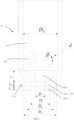
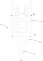
FIG. 1 is a schematic cross-sectional view of an electronic expansion valve according to a first embodiment of the present disclosure. -
FIG. 2 is a schematic cross-sectional view of a valve needle sleeve assembled with a valve needle inFIG. 1 . -
FIG. 3 is a schematic cross-sectional view of a valve needle sleeve inFIG. 1 . -
FIG. 4 is a schematic cross-sectional view of a valve needle inFIG. 1 . -
FIG. 5 is a schematic cross-sectional view of an electronic expansion valve according to a second embodiment of the present disclosure. -
FIG. 6 is a schematic cross-sectional view of a valve needle sleeve assembled with a valve needle inFIG. 5 . -
FIG. 7 is a schematic cross-sectional view of a valve needle sleeve inFIG. 5 . -
FIG. 8 is a schematic cross-sectional view of a valve needle inFIG. 5 . -
Reference sign Name Reference sign Name 100 electronic expansion valve 2131 first protruding section 1 valve seat 2132 second protruding section 11 main valve cavity 214 main overflow hole 2 valve needle assembly 22 valve needle 21 valve needle sleeve 221 tip portion 211 needle sleeve cavity 222 moving portion 212 main valve port 2221 covering section 2121 first deflector hole section 3 standpipe 2122 second deflector hole section 31 liquid-standing gap 2123 rectification hole section 4 traverse pipe 213 protruding portion 5 annular communicating cavity - The realization of the objective, functional characteristics, and advantages of the present disclosure are further described with reference to the accompanying drawings.
- The technical solutions of embodiments of the present disclosure will be clearly and completely described with reference to the drawings of the present disclosure. Obviously, the described embodiments are only some rather than all of the embodiments of the present disclosure. Based on the embodiments of the present disclosure, all other embodiments obtained by those skilled in the art without creative efforts shall fall within the scope of the present disclosure.
- It should be noted that all directional indicators (such as up, down, left, right, front, rear, etc.) in the embodiments of the present disclosure are only used to explain the relative positional relationship, movement situation, etc. among components in a specific attitude (as shown in the drawings). If the specific attitude changes, the directional indication also changes accordingly.
- In addition, the descriptions related to "first", "second" and the like in the present disclosure are merely for descriptive purposes, and should not be understood as indicating or implying their relative importance or implicitly indicating the number of technical features indicated. Therefore, the features defined by "first" and "second" may explicitly or implicitly include at least one such feature. Besides, the various embodiments can be combined with each other, but the combination must be based on what can be achieved by those skilled in the art. When the combination of the embodiments is contradictory or cannot be achieved, it should be considered that such combination does not exist, or is not within the scope of the present disclosure.
- Currently, there is a strong refrigerant sound during the using process of electronic expansion valves. When using such electronic expansion valves, air conditioner manufacturers usually need to add transition tubes or capillary tubes before and after throttling. On the one hand, the noise reduction effect is not obvious and the means is not universal. On the other hand, the pipeline becomes more complicate, the space occupied by the pipeline becomes wider, the number of solder joints increases, and the risk of leakage increases. In addition, it will decrease the production efficiency and increase the manufacturing cost. Therefore, it is necessary to optimize the structure of the electronic expansion valve.
- In view of this, the present disclosure provides an
electronic expansion valve 100.FIG.1 to FIG. 8 are schematic views of electronic expansion valve 100s according to some embodiments of the present disclosure. - As shown in
FIG. 1 to FIG. 4 , theelectronic expansion valve 100 comprises avalve seat 1 and avalve needle assembly 2. Thevalve seat 1 is formed with amain valve cavity 11 and thevalve needle assembly 2 comprises avalve needle sleeve 21 provided inside themain valve cavity 11. Thevalve needle sleeve 21 is formed with aneedle sleeve cavity 211 and an end wall of theneedle sleeve cavity 211 is defined with amain valve port 212. Themain valve port 212 comprises a firstdeflector hole section 2121, a seconddeflector hole section 2122 and arectification hole section 2123. The firstdeflector hole section 2121 and the seconddeflector hole section 2122 are distributed along a direction towards an outside of themain valve port 212 and therectification hole section 2123 is provided between the firstdeflector hole section 2121 and the seconddeflector hole section 2122. Therectification hole section 2123 is connected with the firstdeflector hole section 2121. In addition, the pore size of therectification hole section 2123 is larger than the pore size of the firstdeflector hole section 2121 to make therectification hole section 2123 and an inner wall of the firstdeflector hole section 2121 cooperatively form a step. - In the technical solutions of the disclosure, the
valve seat 1 is formed with amain valve cavity 11 and thevalve needle assembly 2 comprises avalve needle sleeve 21 provided inside themain valve cavity 11. Thevalve needle sleeve 21 is formed with aneedle sleeve cavity 211 and an end wall of theneedle sleeve cavity 211 is defined with amain valve port 212. Themain valve port 212 comprises a firstdeflector hole section 2121, a seconddeflector hole section 2122 and arectification hole section 2123. The firstdeflector hole section 2121 and the seconddeflector hole section 2122 are distributed along a direction towards an outside of themain valve port 212 and therectification hole section 2123 is provided between the firstdeflector hole section 2121 and the seconddeflector hole section 2122. Therectification hole section 2123 is connected with the firstdeflector hole section 2121. In addition, the pore size of therectification hole section 2123 is larger than the pore size of the firstdeflector hole section 2121 to make therectification hole section 2123 and an inner wall of the firstdeflector hole section 2121 cooperatively form a step. When theelectronic expansion valve 100 is working, the refrigerant passes through therectification hole section 2123. Meanwhile, the turbulence will be formed at a location of therectification hole section 2123 corresponding to the step. The turbulence may guide the refrigerant at the central position ofmain valve port 212 to flow to play a flexible guide effect, thereby improving the flowing state of the refrigerant at themain valve port 212 and effectively reducing the refrigerant noise. - It should be noted that the
valve needle assembly 2 comprises avalve needle 22 provided inside thevalve needle sleeve 21. Thevalve needle 22 is adjustable to move along a length direction of thevalve needle sleeve 21 and atip portion 221 of thevalve needle 22 is provided at least partially inside themain valve port 212. By controlling the movement of thevalve needle 22 along the length direction of thevalve needle sleeve 21, the gap between theneedle sleeve cavity 211 and themain valve port 212 is adjusted to intercommunicate themain valve cavity 11 and themain valve port 212, thereby changing the pressure of the liquid in themain valve cavity 11 and themain valve port 212. - In addition, the
electronic expansion valve 100 also comprises a driving mechanism for driving thevalve needle 22. The driving mechanism comprises a rotor member, a stator member, a thread driving member, and a stop member. The above structures cooperate with each other to realize the movement of thevalve needle 22 along the length direction of thevalve needle sleeve 21. It should be noted that the driving mechanism is applied in theelectronic expansion valve 100 in the prior art, which will not be described in detail here. In addition, the entire sealing structure of theelectronic expansion valve 100 is also applied in theelectronic expansion valve 100 in the prior art, and will not be described in detail here. - In the flowing path of the
electronic expansion valve 100, the liquid flows in from or out to the side of theelectronic expansion valve 100, that is, the liquid flows in or out along a axial direction. In order to reduce the refrigerant noise made in the entire flowing path, in the embodiment of the present disclosure, improvements are made to the relevant structures on the horizontal flowing path, and also to the relevant structures on the vertical flowing path. - As for the structural improvement on the vertical flowing path, it is mainly to optimize the structure of the
main valve port 212. As mentioned above, arectification hole section 2123 is added between the firstdeflector hole section 2121 and the seconddeflector hole section 2122, thereby flexibly guiding the liquid, improving the flowing state of the refrigerant at themain valve port 212, and effectively reducing the noise of the refrigerant. It should be noted that the number of therectification hole sections 2123 may be one, two or more, which is not limited. - The following will only illustrate the embodiments with one
rectification hole section 2123. The refrigerant noise is affected by the size relationship among every hole section of themain valve port 212. In an embodiment, D represents the pore size of the firstdeflector hole section 2121 and D1 represents the pore size of therectification hole section 2123, and D1/D is not less than 2. On the one hand, the flowing of the refrigerant should be fully considered. On the other hand, the turbulence will be formed at a location of therectification hole section 2123 corresponding to the step. Taking the above factors into consideration, when D1/D is not less than 2, the noise of the refrigerant can be significantly reduced, which has a good effect. - The
valve needle 22 limits the middle segment shape of the fluid flowing in from or out to themain valve port 212, and the inner side wall of themain valve port 212 limits the edge segment shape of the fluid flowing in from or out to themain valve port 212. Both of the above two have a great influence on the flowing of refrigerant. In an embodiment, thevalve needle assembly 2 further comprises avalve needle 22 provided inside thevalve needle sleeve 21. Thetip portion 221 of thevalve needle 22 is at least partially provided inside themain valve port 212. L represents a distance between an end face of thetip portion 221 and a bottom wall of theneedle sleeve cavity 211; L1 represents a length of the firstdeflector hole section 2121; L2 represents a length of therectification hole section 2123; and L3 represents a length of the seconddeflector hole section 2122, and L is not less than L1+L2+L3 and not greater than 1.5(L1+L2+L3). If the length of thetip portion 221 of thevalve needle 22 is too long, the processing would become more difficult and the processing cost would increase. - In an embodiment, an end forming the
main valve port 212 of thevalve needle sleeve 21 protrudes outwardly from themain valve cavity 11 to form a protrudingportion 213. Theelectronic expansion valve 100 further comprises astandpipe 3 and an end of thestandpipe 3 sleeve externally on the protrudingportion 213. DL represents an inner diameter of thestandpipe 3 and D2 represents an inner diameter of an end of themain valve port 212, and (DL-D2)/D2 is not less than 0.1 and not greater than 0.4. If the ratio is too small, the guiding effect will not be achieved. If the ratio is too large, the guiding effect will be too strong, and a strong secondary flow will be formed before the second shrinkage guiding section. When (DL-D2)/D2 is not less than 0.1 and not greater than 0.4, it can not only play a better guiding role, but also weaken the secondary flow, thereby achieving a good flow guiding effect. - In an embodiment, D1 represents the pore size of the
rectification hole section 2123 and D1/D2 is not less than 0.65 and not greater than 0.85. Within this range, the refrigerant diversion between the seconddeflector hole section 2122 and therectification hole section 2123 is stable. - As shown from
FIG. 4 to FIG. 8 , there are some schematic structural views according to a second embodiment of the present disclosure. In the embodiment, a lateral surface of the protrudingportion 213 is shaped like a step. The protrudingportion 213 comprises afirst protruding section 2131 with a larger pore size and asecond protruding section 2132 with a smaller pore size sequentially connected along the direction towards the outside of themain valve port 212. Thestandpipe 3 sleeves externally on the first protrudingsection 2131 and a liquid-standinggap 31 is formed between thesecond protruding section 2132 and thestandpipe 3. At this time, the refrigerant in the liquid-standinggap 31 may guide the refrigerant flowing through the inner wall of thestandpipe 3 to flow to play a flexible guide effect, thereby improving the flowing state of the refrigerant at themain valve port 212, reducing the friction between the refrigerant and the protrudingportion 213 and effectively reducing the refrigerant noise of theelectronic expansion valve 100. - In addition, in an embodiments, along the direction towards the outside of the
main valve port 212, an inner diameter of the seconddeflector hole section 2122 is configured to gradually increase, and an inner wall of an end of the seconddeflector hole section 2122 is connected with an lateral surface of thesecond protruding section 2132. In this way, it further reduce the friction between the refrigerant and the protrudingportion 213, thereby effectively reducing the refrigerant noise of theelectronic expansion valve 100. - The size of the liquid-standing
gap 31 is a factor that affects the refrigerant noise. In an embodiment, L4 represents a length of the first protrudingsection 2131 and L5 represents a length of thesecond protruding section 2132, and L4/L5 is not less than 0.4 and not greater than 0.85. Within this size relationship range, the refrigerant noise of theelectronic expansion valve 100 is reduced obviously, thereby having a better effect. - Moreover, a size relationship between the inner wall of the
main valve port 212 and the lateral surface of the protrudingportion 213 also affects the refrigerant sound. In an embodiment, L2 represents a length of therectification hole section 2123 and L3 represents a length of the seconddeflector hole section 2122, and (L2+L3)/(L4+L5) is not less than 0.4 and not greater than 0.85. Within this size relationship range, the refrigerant noise of theelectronic expansion valve 100 is reduced obviously, thereby having a better effect. - An inner sidewall of the
needle sleeve cavity 211 is provided with amain overflow hole 214 communicated with themain valve cavity 11. Theneedle sleeve cavity 211 is communicated with themain valve cavity 11 via themain overflow hole 214. In an embodiment, theelectronic expansion valve 100 further comprises atraverse pipe 4 communicated with themain valve cavity 11. Thetraverse pipe 4 extends along a radial direction of thevalve needle sleeve 21, and themain overflow hole 214 is staggered with thetraverse pipe 4 along the direction towards the outside of themain valve port 212. In this way, the influence exerted by the impact energy of the refrigerant on the flowing of the refrigerant is reduced, which result in that the refrigerant is imported from thetraverse pipe 4. After the refrigerant filling themain valve cavity 11, the refrigerant enters into theneedle sleeve cavity 211 through themain overflow hole 214. In another way, the refrigerant enters into themain valve cavity 11 from theneedle sleeve cavity 211, fills themain valve cavity 11, and then is exported to thetraverse pipe 4, which may reduce the flow rate of the refrigerant which exerts impact tovalve needle 22, thereby improving the reliability and durability. - It should be noted that the number of the
main overflow holes 214 may be plural and a plurality of themain overflow holes 214 are spaced along a circumference of themain valve cavity 11, which may ensure the fluidity of the refrigerant between themain valve cavity 11 and theneedle sleeve cavity 211. - In order to avoid the direct impact of the refrigerant on the
valve needle 22 and the abnormal refrigerant sound caused, in an embodiment, β represents an comprised angle between a centerline of themain overflow hole 214 and a radial plane of thevalve needle sleeve 21, and β is not less than 30° and not greater than 60°. A better value is that β is equal to 45°. In this way, the flow rate of the refrigerant is ensured, and at the same time, the direct impact of the refrigerant on thevalve needle 22 is reduced as much as possible, which may further reduce the noise of the refrigerant. - In an embodiment, DS represents an inner diameter of the
needle sleeve cavity 211 and d represents a pore size of themain overflow hole 214, d is greater than 1.8 mm and less than 0.71Ds. Within the range of this size relationship, the noise of the refrigerant can be significantly reduced, which has a good effect. In addition, the lower edge of themain overflow hole 214 can be provided at the position adjacent to the bottom wall of themain valve cavity 11. - In order to reduce the shaking between the
valve needle sleeve 21 and the valve sleeve, the gap between the two is very small. However, after the overflow hole is enlarged, thevalve needle sleeve 21 will block a part of the overflow hole in the fully closed state, resulting in obstruction of the flowing. In an embodiment, thevalve needle assembly 2 further comprises avalve needle 22 provided inside thevalve needle sleeve 21. Thevalve needle 22 comprises a movingportion 222 hermetically sealed with and slidably mounted inside thevalve needle sleeve 21 and atip portion 221 connected with the movingportion 222 and at least partially provided inside themain valve port 212. The movingportion 222 comprises acovering section 2221 at least partially covering themain overflow hole 214, and at least thecovering section 2221 of the movingportion 222 is provided in a decreased size, so as to form an annular communicatingcavity 5 communicated with themain overflow hole 214 between thecovering section 2221 and thevalve needle sleeve 21. The covered part of themain overflow hole 214 is communicated by the annular communicatingcavity 5, thereby reducing the influence on the refrigerant and improving the efficiency of theelectronic expansion valve 100. - In an embodiment, Df2 represents an outer diameter of the
covering section 2221 and DS represents an inner diameter of theneedle sleeve cavity 211, and Df2/DS is greater than 0.8 and less than 0.98. Within the range of this size relationship, the flowing state of the refrigerant is improved. - In an embodiment, Lp represents a distance between an end face of the
covering section 2221 away from themain valve port 212 and an end face of thevalve needle sleeve 21 away from themain valve port 212, and Lp/DS is not less than 0.8 and not greater than 1.7. In this way, the vibration of thevalve needle 22 caused by the impact of the refrigerant is reduced, and the noise of the refrigerant of theelectronic expansion valve 100 is significantly improved, which has a good effect. - The present disclosure further provides a refrigerant circulation line. The refrigerant circulation line comprises an electronic expansion valve. The refrigerant circulation line comprises all technical solutions of the electronic expansion valve above-mentioned. Thus, it has at least all the beneficial effects brought by the technical solutions of the above-mentioned embodiments, which will not be repeated here.
- The present disclosure further provides an air conditioner system. The air conditioner system comprises a refrigerant circulation line. The refrigerant circulation line comprises an electronic expansion valve. The air conditioner system comprises all technical solutions of the refrigerant circulation line above-mentioned. Thus, it has at least all the beneficial effects brought by the technical solutions of the above-mentioned embodiments, which will not be repeated here.
- The above are only some embodiments of the present disclosure, and do not limit the scope of the present disclosure thereto. Under the concept of the present disclosure, equivalent structural transformations made according to the description and drawings of the present disclosure, or direct/indirect disclosure in other related technical fields are comprised in the scope of the present disclosure.
Claims (21)
- An electronic expansion valve, characterized by comprising:a valve seat formed with a main valve cavity; anda valve needle assembly comprising a valve needle sleeve provided inside the main valve cavity,wherein the valve needle sleeve is formed with a needle sleeve cavity and an end wall of the needle sleeve cavity is defined with a main valve port,the main valve port comprises:a first deflector hole section;a second deflector hole section, wherein the first deflector hole section and the second deflector hole section being distributed along a direction towards an outside of the main valve port; anda rectification hole section provided between the first deflector hole section and the second deflector hole section, wherein the rectification hole section being connected with the first deflector hole section, andwherein a pore size of the rectification hole section is larger than a pore size of the first deflector hole section, so as to form a step between the rectification hole section and an inner wall of the first deflector hole section.
- The electronic expansion valve of claim 1, wherein:D represents the pore size of the first deflector hole section and D1 represents the pore size of the rectification hole section, andD1/D is not less than 2.
- The electronic expansion valve of claim 1, wherein:the valve needle assembly further comprises a valve needle provided inside the valve needle sleeve,a tip portion of the valve needle is at least partially provided inside the main valve port,L represents a distance between an end face of the tip portion and a bottom wall of the needle sleeve cavity; L1 represents a length of the first deflector hole section; L2 represents a length of the rectification hole section; and L3 represents a length of the second deflector hole section, andL is not less than L1+L2+L3 and not greater than 1.5(L1+L2+L3).
- The electronic expansion valve of claim 1, wherein:an end of the valve needle sleeve forming the main valve port protrudes outwardly from the main valve cavity to form a protruding portion,the electronic expansion valve further comprises a standpipe, and an end of the standpipe sleeves externally on the protruding portion,DL represents an inner diameter of the standpipe and D2 represents an inner diameter of an end of the main valve port, and(DL-D2)/D2 is not less than 0.1 and not greater than 0.4.
- The electronic expansion valve of claim 4, wherein:D1 represents the pore size of the rectification hole section, andD1/D2 is not less than 0.65 and not greater than 0.85.
- The electronic expansion valve of claim 4, wherein:a lateral surface of the protruding portion is shaped like a step,along the direction towards the outside of the main valve port, the protruding portion comprises a first protruding section with a larger pore size and a second protruding section with a smaller pore size, wherein the first protruding section and the second protruding section being sequentially connected, andthe standpipe sleeves externally on the first protruding section, and a liquid-standing gap is formed between the second protruding section and the standpipe.
- The electronic expansion valve of claim 6, wherein:an inner diameter of the second deflector hole section gradually increases along the direction towards the outside of the main valve port, andan inner wall of an end of the second deflector hole section is connected with an lateral surface of the second protruding section.
- The electronic expansion valve of claim 6, wherein:L4 represents a length of the first protruding section and L5 represents a length of the second protruding section, andL4/L5 is not less than 0.4 and not greater than 0.85.
- The electronic expansion valve of claim 4, wherein:L2 represents a length of the rectification hole section and L3 represents a length of the second deflector hole section, and(L2+L3)/(L4+L5) is not less than 0.4 and not greater than 0.85.
- The electronic expansion valve of claim 1, wherein an inner sidewall of the needle sleeve cavity is provided with a main overflow hole communicated with the main valve cavity.
- The electronic expansion valve of claim 10, wherein:the electronic expansion valve further comprises a traverse pipe communicated with the main valve cavity,the traverse pipe extends along a radial direction of the valve needle sleeve, andthe main overflow hole is staggered with the traverse pipe along the direction towards the outside of the main valve port.
- The electronic expansion valve of claim 10, wherein:β represents an included angle between a centerline of the main overflow hole and a radial plane of the valve needle sleeve, andβ is not less than 30° and not greater than 60°.
- The electronic expansion valve of claim 12, wherein β is equal to 45°.
- The electronic expansion valve of claim 10, wherein:DS represents an inner diameter of the needle sleeve cavity and d represents a pore size of the main overflow hole, andd is greater than 1.8 mm and less than 0.71Ds.
- The electronic expansion valve of claim 10, wherein a plurality of the main overflow holes are spaced along a circumference of the main valve cavity.
- The electronic expansion valve of claim 10, wherein:the valve needle assembly further comprises a valve needle provided inside the valve needle sleeve,the valve needle comprises:a moving portion hermetically sealed with and slidably mounted inside the valve needle sleeve; anda tip portion connected with the moving portion and at least partially provided inside the main valve port,the moving portion comprises a covering section at least partially covering the main overflow hole, andat least the covering section of the moving portion is provided in a decreased size, so as to form an annular communicating cavity communicated with the main overflow hole between the covering section and the valve needle sleeve.
- The electronic expansion valve of claim 16, wherein:Df2 represents an outer diameter of the covering section and DS represents an inner diameter of the needle sleeve cavity, andDf2/DS is greater than 0.8 and less than 0.98.
- The electronic expansion valve of claim 17, wherein:Lp represents a distance between an end face of the covering section away from the main valve port and an end face of the valve needle sleeve away from the main valve port, andLp/Ds is not less than 0.8 and not greater than 1.7.
- The electronic expansion valve of claim 1, wherein:the valve needle assembly comprises a valve needle provided inside the valve needle sleeve,the valve needle is movable along a length direction of the valve needle sleeve for adjustment, anda tip portion of the valve needle is provided at least partially inside the main valve port.
- A refrigerant circulation line, characterized by comprising an electronic expansion valve of any one of claims 1 to 19.
- An air conditioner system, characterized by comprising a refrigerant circulation line of claim 20.
Applications Claiming Priority (3)
| Application Number | Priority Date | Filing Date | Title |
|---|---|---|---|
| CN202010991712.XA CN114278744B (en) | 2020-09-18 | 2020-09-18 | Electronic expansion valve, refrigerant circulation pipeline and air conditioner system |
| CN202022064983.9U CN212318817U (en) | 2020-09-18 | 2020-09-18 | Electronic expansion valve, refrigerant circulation pipeline and air conditioner system |
| PCT/CN2021/106390 WO2022057421A1 (en) | 2020-09-18 | 2021-07-15 | Electronic expansion valve, refrigerant circulation pipeline, and air conditioner system |
Publications (4)
| Publication Number | Publication Date |
|---|---|
| EP4160068A1 true EP4160068A1 (en) | 2023-04-05 |
| EP4160068A4 EP4160068A4 (en) | 2023-11-22 |
| EP4160068C0 EP4160068C0 (en) | 2025-05-14 |
| EP4160068B1 EP4160068B1 (en) | 2025-05-14 |
Family
ID=80775874
Family Applications (1)
| Application Number | Title | Priority Date | Filing Date |
|---|---|---|---|
| EP21868250.8A Active EP4160068B1 (en) | 2020-09-18 | 2021-07-15 | Electronic expansion valve, refrigerant circulation pipeline, and air conditioner system |
Country Status (2)
| Country | Link |
|---|---|
| EP (1) | EP4160068B1 (en) |
| WO (1) | WO2022057421A1 (en) |
Families Citing this family (1)
| Publication number | Priority date | Publication date | Assignee | Title |
|---|---|---|---|---|
| JP7422409B2 (en) * | 2021-06-10 | 2024-01-26 | 株式会社不二工機 | electric valve |
Family Cites Families (8)
| Publication number | Priority date | Publication date | Assignee | Title |
|---|---|---|---|---|
| JP2004340260A (en) * | 2003-05-15 | 2004-12-02 | Saginomiya Seisakusho Inc | Flow control valve |
| JP5480753B2 (en) * | 2010-08-25 | 2014-04-23 | 株式会社鷺宮製作所 | Motorized valve |
| CN202973684U (en) * | 2012-11-06 | 2013-06-05 | 浙江盾安禾田金属有限公司 | Electronic expansion valve |
| JP6639876B2 (en) * | 2015-11-17 | 2020-02-05 | 株式会社不二工機 | Flow control valve |
| JP6479648B2 (en) * | 2015-12-24 | 2019-03-06 | 株式会社鷺宮製作所 | Motorized valve |
| JP6659624B2 (en) * | 2017-06-23 | 2020-03-04 | 株式会社鷺宮製作所 | Motorized valve and refrigeration cycle system |
| JP6740179B2 (en) * | 2017-06-23 | 2020-08-12 | 株式会社鷺宮製作所 | Motorized valve and refrigeration cycle system |
| CN212318817U (en) * | 2020-09-18 | 2021-01-08 | 广东美的制冷设备有限公司 | Electronic expansion valve, refrigerant circulation pipeline and air conditioner system |
-
2021
- 2021-07-15 WO PCT/CN2021/106390 patent/WO2022057421A1/en not_active Ceased
- 2021-07-15 EP EP21868250.8A patent/EP4160068B1/en active Active
Also Published As
| Publication number | Publication date |
|---|---|
| EP4160068C0 (en) | 2025-05-14 |
| EP4160068A4 (en) | 2023-11-22 |
| WO2022057421A1 (en) | 2022-03-24 |
| EP4160068B1 (en) | 2025-05-14 |
Similar Documents
| Publication | Publication Date | Title |
|---|---|---|
| EP4242498A1 (en) | Electronic expansion valve and refrigeration device | |
| US20240392909A1 (en) | Connecting Pipe Assembly and Control Valve Assembly with Connecting Pipe Assembly | |
| EP4160068A1 (en) | Electronic expansion valve, refrigerant circulation pipeline, and air conditioner system | |
| CN212318817U (en) | Electronic expansion valve, refrigerant circulation pipeline and air conditioner system | |
| KR20250129094A (en) | Switching valves and air conditioning systems | |
| CN111238096A (en) | An air conditioner and its throttle valve | |
| CN102589205B (en) | A kind of electric expansion valve | |
| US20250109799A1 (en) | Stop valve | |
| CN220668420U (en) | Electronic expansion valve and refrigeration system | |
| CN217977421U (en) | Shut-off valve | |
| CN109990129A (en) | Electromagnetic switching valve | |
| CN219868611U (en) | Electronic expansion valve | |
| CN212253247U (en) | Air conditioner and throttle valve thereof | |
| CN218178079U (en) | Noise reduction device and electronic expansion valve | |
| KR20240025015A (en) | Three-way pipe and air conditioning system using the three-way pipe | |
| EP4382786A1 (en) | Valve needle and electronic expansion valve having same | |
| CN224064997U (en) | Expansion and contraction pipeline for preventing capillary tube from being blocked by welding | |
| CN218913826U (en) | Switching valve and air conditioning system | |
| US12618476B2 (en) | Electronic expansion valve and refrigeration device | |
| CN223512318U (en) | Electronic expansion valve and air conditioning system with same | |
| CN101762128A (en) | Thermal expansion valve | |
| JP7855146B2 (en) | Switching valves and air conditioning systems | |
| CN220185898U (en) | Switching valve | |
| CN223165766U (en) | Electronic expansion valve and refrigeration equipment | |
| CN216200982U (en) | Pilot valve and four-way valve |
Legal Events
| Date | Code | Title | Description |
|---|---|---|---|
| STAA | Information on the status of an ep patent application or granted ep patent |
Free format text: STATUS: THE INTERNATIONAL PUBLICATION HAS BEEN MADE |
|
| PUAI | Public reference made under article 153(3) epc to a published international application that has entered the european phase |
Free format text: ORIGINAL CODE: 0009012 |
|
| STAA | Information on the status of an ep patent application or granted ep patent |
Free format text: STATUS: REQUEST FOR EXAMINATION WAS MADE |
|
| 17P | Request for examination filed |
Effective date: 20221230 |
|
| AK | Designated contracting states |
Kind code of ref document: A1 Designated state(s): AL AT BE BG CH CY CZ DE DK EE ES FI FR GB GR HR HU IE IS IT LI LT LU LV MC MK MT NL NO PL PT RO RS SE SI SK SM TR |
|
| A4 | Supplementary search report drawn up and despatched |
Effective date: 20231020 |
|
| RIC1 | Information provided on ipc code assigned before grant |
Ipc: F25B 41/31 20210101ALI20231016BHEP Ipc: F16K 31/04 20060101ALI20231016BHEP Ipc: F16K 47/02 20060101AFI20231016BHEP |
|
| DAV | Request for validation of the european patent (deleted) | ||
| DAX | Request for extension of the european patent (deleted) | ||
| GRAP | Despatch of communication of intention to grant a patent |
Free format text: ORIGINAL CODE: EPIDOSNIGR1 |
|
| STAA | Information on the status of an ep patent application or granted ep patent |
Free format text: STATUS: GRANT OF PATENT IS INTENDED |
|
| INTG | Intention to grant announced |
Effective date: 20250304 |
|
| GRAS | Grant fee paid |
Free format text: ORIGINAL CODE: EPIDOSNIGR3 |
|
| GRAA | (expected) grant |
Free format text: ORIGINAL CODE: 0009210 |
|
| STAA | Information on the status of an ep patent application or granted ep patent |
Free format text: STATUS: THE PATENT HAS BEEN GRANTED |
|
| AK | Designated contracting states |
Kind code of ref document: B1 Designated state(s): AL AT BE BG CH CY CZ DE DK EE ES FI FR GB GR HR HU IE IS IT LI LT LU LV MC MK MT NL NO PL PT RO RS SE SI SK SM TR |
|
| REG | Reference to a national code |
Ref country code: GB Ref legal event code: FG4D |
|
| REG | Reference to a national code |
Ref country code: CH Ref legal event code: EP |
|
| REG | Reference to a national code |
Ref country code: IE Ref legal event code: FG4D |
|
| REG | Reference to a national code |
Ref country code: DE Ref legal event code: R096 Ref document number: 602021030923 Country of ref document: DE |
|
| U01 | Request for unitary effect filed |
Effective date: 20250605 |
|
| U07 | Unitary effect registered |
Designated state(s): AT BE BG DE DK EE FI FR IT LT LU LV MT NL PT RO SE SI Effective date: 20250613 |
|
| U20 | Renewal fee for the european patent with unitary effect paid |
Year of fee payment: 5 Effective date: 20250722 |
|
| PG25 | Lapsed in a contracting state [announced via postgrant information from national office to epo] |
Ref country code: ES Free format text: LAPSE BECAUSE OF FAILURE TO SUBMIT A TRANSLATION OF THE DESCRIPTION OR TO PAY THE FEE WITHIN THE PRESCRIBED TIME-LIMIT Effective date: 20250514 |
|
| PG25 | Lapsed in a contracting state [announced via postgrant information from national office to epo] |
Ref country code: NO Free format text: LAPSE BECAUSE OF FAILURE TO SUBMIT A TRANSLATION OF THE DESCRIPTION OR TO PAY THE FEE WITHIN THE PRESCRIBED TIME-LIMIT Effective date: 20250814 Ref country code: GR Free format text: LAPSE BECAUSE OF FAILURE TO SUBMIT A TRANSLATION OF THE DESCRIPTION OR TO PAY THE FEE WITHIN THE PRESCRIBED TIME-LIMIT Effective date: 20250815 |
|
| PG25 | Lapsed in a contracting state [announced via postgrant information from national office to epo] |
Ref country code: PL Free format text: LAPSE BECAUSE OF FAILURE TO SUBMIT A TRANSLATION OF THE DESCRIPTION OR TO PAY THE FEE WITHIN THE PRESCRIBED TIME-LIMIT Effective date: 20250514 |
|
| PG25 | Lapsed in a contracting state [announced via postgrant information from national office to epo] |
Ref country code: HR Free format text: LAPSE BECAUSE OF FAILURE TO SUBMIT A TRANSLATION OF THE DESCRIPTION OR TO PAY THE FEE WITHIN THE PRESCRIBED TIME-LIMIT Effective date: 20250514 |
|
| PG25 | Lapsed in a contracting state [announced via postgrant information from national office to epo] |
Ref country code: RS Free format text: LAPSE BECAUSE OF FAILURE TO SUBMIT A TRANSLATION OF THE DESCRIPTION OR TO PAY THE FEE WITHIN THE PRESCRIBED TIME-LIMIT Effective date: 20250814 |
|
| PG25 | Lapsed in a contracting state [announced via postgrant information from national office to epo] |
Ref country code: IS Free format text: LAPSE BECAUSE OF FAILURE TO SUBMIT A TRANSLATION OF THE DESCRIPTION OR TO PAY THE FEE WITHIN THE PRESCRIBED TIME-LIMIT Effective date: 20250914 |
|
| PG25 | Lapsed in a contracting state [announced via postgrant information from national office to epo] |
Ref country code: SM Free format text: LAPSE BECAUSE OF FAILURE TO SUBMIT A TRANSLATION OF THE DESCRIPTION OR TO PAY THE FEE WITHIN THE PRESCRIBED TIME-LIMIT Effective date: 20250514 |
|
| PG25 | Lapsed in a contracting state [announced via postgrant information from national office to epo] |
Ref country code: CZ Free format text: LAPSE BECAUSE OF FAILURE TO SUBMIT A TRANSLATION OF THE DESCRIPTION OR TO PAY THE FEE WITHIN THE PRESCRIBED TIME-LIMIT Effective date: 20250514 |
|
| PG25 | Lapsed in a contracting state [announced via postgrant information from national office to epo] |
Ref country code: SK Free format text: LAPSE BECAUSE OF FAILURE TO SUBMIT A TRANSLATION OF THE DESCRIPTION OR TO PAY THE FEE WITHIN THE PRESCRIBED TIME-LIMIT Effective date: 20250514 |
|
| REG | Reference to a national code |
Ref country code: CH Ref legal event code: H13 Free format text: ST27 STATUS EVENT CODE: U-0-0-H10-H13 (AS PROVIDED BY THE NATIONAL OFFICE) Effective date: 20260224 |
|
| PLBE | No opposition filed within time limit |
Free format text: ORIGINAL CODE: 0009261 |
|
| STAA | Information on the status of an ep patent application or granted ep patent |
Free format text: STATUS: NO OPPOSITION FILED WITHIN TIME LIMIT |
|
| REG | Reference to a national code |
Ref country code: CH Ref legal event code: L10 Free format text: ST27 STATUS EVENT CODE: U-0-0-L10-L00 (AS PROVIDED BY THE NATIONAL OFFICE) Effective date: 20260325 |
|
| 26N | No opposition filed |
Effective date: 20260217 |
|
| PG25 | Lapsed in a contracting state [announced via postgrant information from national office to epo] |
Ref country code: CH Free format text: LAPSE BECAUSE OF NON-PAYMENT OF DUE FEES Effective date: 20250731 |