EP4160059B1 - Ölgekühlte kohlenstoffdichtung - Google Patents
Ölgekühlte kohlenstoffdichtung Download PDFInfo
- Publication number
- EP4160059B1 EP4160059B1 EP22209749.5A EP22209749A EP4160059B1 EP 4160059 B1 EP4160059 B1 EP 4160059B1 EP 22209749 A EP22209749 A EP 22209749A EP 4160059 B1 EP4160059 B1 EP 4160059B1
- Authority
- EP
- European Patent Office
- Prior art keywords
- seal
- seat
- annular channel
- face
- seal system
- Prior art date
- Legal status (The legal status is an assumption and is not a legal conclusion. Google has not performed a legal analysis and makes no representation as to the accuracy of the status listed.)
- Active
Links
Images


Classifications
-
- F—MECHANICAL ENGINEERING; LIGHTING; HEATING; WEAPONS; BLASTING
- F01—MACHINES OR ENGINES IN GENERAL; ENGINE PLANTS IN GENERAL; STEAM ENGINES
- F01D—NON-POSITIVE DISPLACEMENT MACHINES OR ENGINES, e.g. STEAM TURBINES
- F01D11/00—Preventing or minimising internal leakage of working-fluid, e.g. between stages
- F01D11/003—Preventing or minimising internal leakage of working-fluid, e.g. between stages by packing rings; Mechanical seals
-
- F—MECHANICAL ENGINEERING; LIGHTING; HEATING; WEAPONS; BLASTING
- F01—MACHINES OR ENGINES IN GENERAL; ENGINE PLANTS IN GENERAL; STEAM ENGINES
- F01D—NON-POSITIVE DISPLACEMENT MACHINES OR ENGINES, e.g. STEAM TURBINES
- F01D25/00—Component parts, details, or accessories, not provided for in, or of interest apart from, other groups
- F01D25/18—Lubricating arrangements
- F01D25/183—Sealing means
-
- F—MECHANICAL ENGINEERING; LIGHTING; HEATING; WEAPONS; BLASTING
- F01—MACHINES OR ENGINES IN GENERAL; ENGINE PLANTS IN GENERAL; STEAM ENGINES
- F01D—NON-POSITIVE DISPLACEMENT MACHINES OR ENGINES, e.g. STEAM TURBINES
- F01D25/00—Component parts, details, or accessories, not provided for in, or of interest apart from, other groups
- F01D25/18—Lubricating arrangements
- F01D25/20—Lubricating arrangements using lubrication pumps
-
- F—MECHANICAL ENGINEERING; LIGHTING; HEATING; WEAPONS; BLASTING
- F02—COMBUSTION ENGINES; HOT-GAS OR COMBUSTION-PRODUCT ENGINE PLANTS
- F02C—GAS-TURBINE PLANTS; AIR INTAKES FOR JET-PROPULSION PLANTS; CONTROLLING FUEL SUPPLY IN AIR-BREATHING JET-PROPULSION PLANTS
- F02C7/00—Features, components parts, details or accessories, not provided for in, or of interest apart form groups F02C1/00 - F02C6/00; Air intakes for jet-propulsion plants
- F02C7/06—Arrangements of bearings; Lubricating
-
- F—MECHANICAL ENGINEERING; LIGHTING; HEATING; WEAPONS; BLASTING
- F02—COMBUSTION ENGINES; HOT-GAS OR COMBUSTION-PRODUCT ENGINE PLANTS
- F02C—GAS-TURBINE PLANTS; AIR INTAKES FOR JET-PROPULSION PLANTS; CONTROLLING FUEL SUPPLY IN AIR-BREATHING JET-PROPULSION PLANTS
- F02C7/00—Features, components parts, details or accessories, not provided for in, or of interest apart form groups F02C1/00 - F02C6/00; Air intakes for jet-propulsion plants
- F02C7/28—Arrangement of seals
-
- F—MECHANICAL ENGINEERING; LIGHTING; HEATING; WEAPONS; BLASTING
- F16—ENGINEERING ELEMENTS AND UNITS; GENERAL MEASURES FOR PRODUCING AND MAINTAINING EFFECTIVE FUNCTIONING OF MACHINES OR INSTALLATIONS; THERMAL INSULATION IN GENERAL
- F16J—PISTONS; CYLINDERS; SEALINGS
- F16J15/00—Sealings
- F16J15/16—Sealings between relatively-moving surfaces
- F16J15/34—Sealings between relatively-moving surfaces with slip-ring pressed against a more or less radial face on one member
- F16J15/3404—Sealings between relatively-moving surfaces with slip-ring pressed against a more or less radial face on one member and characterised by parts or details relating to lubrication, cooling or venting of the seal
-
- F—MECHANICAL ENGINEERING; LIGHTING; HEATING; WEAPONS; BLASTING
- F05—INDEXING SCHEMES RELATING TO ENGINES OR PUMPS IN VARIOUS SUBCLASSES OF CLASSES F01-F04
- F05D—INDEXING SCHEME FOR ASPECTS RELATING TO NON-POSITIVE-DISPLACEMENT MACHINES OR ENGINES, GAS-TURBINES OR JET-PROPULSION PLANTS
- F05D2240/00—Components
- F05D2240/55—Seals
- F05D2240/58—Piston ring seals
-
- F—MECHANICAL ENGINEERING; LIGHTING; HEATING; WEAPONS; BLASTING
- F05—INDEXING SCHEMES RELATING TO ENGINES OR PUMPS IN VARIOUS SUBCLASSES OF CLASSES F01-F04
- F05D—INDEXING SCHEME FOR ASPECTS RELATING TO NON-POSITIVE-DISPLACEMENT MACHINES OR ENGINES, GAS-TURBINES OR JET-PROPULSION PLANTS
- F05D2260/00—Function
- F05D2260/20—Heat transfer, e.g. cooling
- F05D2260/232—Heat transfer, e.g. cooling characterized by the cooling medium
-
- Y—GENERAL TAGGING OF NEW TECHNOLOGICAL DEVELOPMENTS; GENERAL TAGGING OF CROSS-SECTIONAL TECHNOLOGIES SPANNING OVER SEVERAL SECTIONS OF THE IPC; TECHNICAL SUBJECTS COVERED BY FORMER USPC CROSS-REFERENCE ART COLLECTIONS [XRACs] AND DIGESTS
- Y02—TECHNOLOGIES OR APPLICATIONS FOR MITIGATION OR ADAPTATION AGAINST CLIMATE CHANGE
- Y02T—CLIMATE CHANGE MITIGATION TECHNOLOGIES RELATED TO TRANSPORTATION
- Y02T50/00—Aeronautics or air transport
- Y02T50/60—Efficient propulsion technologies, e.g. for aircraft
Definitions
- the disclosure relates to gas turbine engines. More particularly, the disclosure relates to cooling of carbon seals in gas turbine engines.
- Carbon seals are commonly used to seal between relatively rotating components in gas turbine engines.
- the annular carbon seal is spring biased into engagement with an annular seat (typically metallic such as a steel).
- the carbon seal is on non-rotating static structure and the seat rotates with one of the engine shafts. The sliding engagement causes frictional heating. The heat must be dissipated. With a rotating seat, it is common to use oil cooling.
- oil-cooled carbon seals are divided into two categories: “dry face” seals wherein the oil passes through passageways in the seat without encountering the interface between seal face and seat face; and “wet face” seals wherein the oil passes through the seat to the interface so that the oil that flows through the seat cools the seat but then lubricates the interface to further reduce heat generation.
- the oil may be delivered through a nozzle and slung radially outward by the rotating component and collected in a radially outwardly closed and inwardly open collection channel from which the passageways extend further radially outward.
- EP 3 382 240 A1 discloses a prior art seal system as set forth in the preamble of claim 1.
- FIG. 1 shows a seal system 100 having a first member 102 carrying a seal 104.
- the exemplary seal 104 is a carbon seal having a seal surface or face 106.
- the exemplary seal 104 is formed as a body of revolution about an axis 500 which is an axis of relative rotation between the first member 102 and a second member 110.
- FIG. 1 further shows an outward radial direction 502.
- the exemplary seal face 106 is a radial face.
- the second member 110 comprises a piece 112 (seat piece) forming a seat for the seal with a seat surface or face 114 in sliding sealing engagement with the seal face 106 at a sealing interface.
- the exemplary illustrated configuration is a dry face configuration.
- the seal 104 may be biased into axially compressive engagement with the seat face 114 via one or more factors including pressure bias and spring loading.
- the seal 104 is shown as sealing a space or region 120 inboard of the sealing interface from a space or region 122 outboard. Depending upon configuration, the pressure difference may bias the seal in either direction.
- FIG. 1 further shows a spring 124 (e.g., a coil spring) providing the required bias. There may be a circumferential array of such springs about the axis 500 each under axial compression.
- the second member 110 is rotating in an inertial frame of reference while the first member 102 is either stationary or counter-rotating.
- the rotating of the second member 110 may create a centrifugal oil flow action discussed further below.
- FIG. 1A shows the seat piece 112 as having an annular channel 130 axially spaced from the seat face 114.
- the exemplary annular channel 130 extends from a radially inboard inner diameter (ID) base 132 to a radially outboard outer diameter (OD) opening 134 in an OD surface 136 of the seat piece 112.
- the channel 130 also has a first surface or face 140 and a second surface or face 142 axially spaced therefrom.
- the channel 130 may be machined in the piece 112 by conventional methods, such as turning or milling, or advanced methods, such as EDM.
- FIG. 1A further shows a circumferential array of passageway legs (passageways) 150 connected to the annular channel 130 at respective first ends 152 and open to a surface portion 156 of the piece 112 at their second ends 154.
- An exemplary number of passageways 150 is 10 to 100, more particularly 20 to 80 or 25 to 55 in seal sizes used on gas turbine engines.
- centrifugal action causes an accumulation 160 of oil to be captured by the second member 110 in a radially outwardly closed collection channel 164.
- the passageway second ends 154 form outlets from the collection channel allowing oil flows 162 to pass outward through the passageways to the channel 130.
- the flows 162 from the individual passageways 150 merge to form a flow 165 in the channel 130.
- the flow 165 flows radially outward to be discharged as a discharge flow 166.
- the radial oil flow 165 in the channel cools the seat piece 112 and, thereby, cools the seat face and seal face.
- FIG. 1A shows a weir formed by an annular member 170 accommodated partially in a radially inwardly open channel 172 in the seat piece 112. A portion of the member 170 protrudes radially inwardly from an opening of the channel 172 at the surface 156.
- FIG. 1 shows an oil pump 180 delivering oil from a reservoir 182 via a conduit 184.
- the conduit 184 may terminate at one or more nozzles 186.
- Each nozzle may have a respective outlet 188 discharging a spray 167 of the oil.
- the sprayed oil collects on a surface of the first member and is slung radially outward as a flow 168 ( FIG. 1 ) to the channel 164. Oil from the flow 166 may be collected and returned to the reservoir 182 by a conventional collection apparatus (not shown).
- FIG. 1A further shows the seat face 106 having a radial span RS 1 and the channel 130 as having a radial span RS 2 .
- the exemplary radial spans are oriented so that the channel 130 fully radially overlaps the seal face 106. This provides a short thermal conductive flowpath for heat to pass from the seat face 114 to the flow 165 in the channel 130.
- FIG. 1A further shows an angle ⁇ 1 between the seal face/seat face on the one hand and the adjacent channel face 140 on the other hand. Exemplary ⁇ 1 is greater than zero. More particularly, with the seal face extending exactly or close to exactly radially, the adjacent portion of the channel face 140 diverges at the angle ⁇ 1 in the radial outward direction.
- exemplary ⁇ 1 may be fairly small in order to maintain cooling effectiveness as the flow 165 progresses radially outward toward the outer diameter (OD) extent of the seal face.
- exemplary ⁇ 1 is 0-30.0°, more particularly, 0-12.0°, 0.5-10.0°, or 1.0-10.0° or 2.0-8.0°.
- the second face 142 may similarly diverge from the first face at an angle ⁇ 2 . But this divergence ⁇ 2 may represent an artifact of manufacturing such as from a tapered bit.
- Exemplary ⁇ 2 is 0° to 30.0°, more particularly 0° to 15.0° or 0° to 10.0° or 0° to 5.0°. Alternative lower ends on those ranges are 1.0° and 3.0°.
- Exemplary span S 1 between the seat face 114 and the channel face 140 is 0.030 inch to 0.250 inch (0.76 mm to 6.35 mm), more narrowly 2.0 mm to 6.0 mm or 2.5 mm to 5.0mm.
- Exemplary channel width S 2 is 0.030 inch to 0.250 inch (0.76 mm to 6.35 mm), more narrowly 1.0 mm to 6.0 mm or 2.0 mm to 6.0 mm or 2.5 mm to 5.0mm.
- An exemplary member 170 may be formed by spiral winding such as used for retaining rings.
- a weir may be integrally machined into seat piece 112.
- the use of the annular channel 130 may have one or more of several advantages relative to any particular baseline.
- the channel 130 may provide more circumferential uniformity of cooling which may help reduce heat generation and wear.
- discrete passages may produce a circumferential array of cool zones interspersed with warmer zones.
- the differential thermal expansion of cool portions of the seat and hot portions of the seat may produce an uneven seat surface generating unnecessary heat and potentially compromising sealing.
- FIG. 2 shows a turbofan engine 20 having an engine case 22 containing a rotor shaft assembly 23.
- An exemplary engine is a turbofan. Alternatives include turbojets, turboprops, turboshafts, and industrial gas turbines.
- the exemplary turbofan is a two-spool turbofan. Via high 24 and low 25 shaft portions of the shaft assembly 23, a high pressure turbine (HPT) section 26 and a low pressure turbine (LPT) section 27 respectively drive a high pressure compressor (HPC) section 28 and a low pressure compressor (LPC) section 30.
- the engine extends along a longitudinal axis (centerline) 500 from a fore end to an aft end. Adjacent the fore end, a shroud (fan case) 40 encircles a fan 42 and is supported by vanes 44.
- An aerodynamic nacelle 41 around the fan case is shown and an aerodynamic nacelle 45 around the engine case is shown.
- an alternative variation involves a three spool (plus fan) engine wherein an intermediate spool comprises an intermediate pressure compressor (IPC) between the LPC and HPC and an intermediate pressure turbine (IPT) between the HPT and LPT.
- IPC intermediate pressure compressor
- IPT intermediate pressure turbine
- the IPT drives a low pressure compressor while the LPT drives a fan, in both cases either directly or indirectly via a transmission mechanism, for example a gearbox.
- the low shaft portion 25 of the rotor shaft assembly 23 drives the fan 42 through a reduction transmission 46.
- An exemplary reduction transmission is an epicyclic transmission, namely a planetary or star gear system.
- FIG 2 also shows at their outboard ends, the vanes 44 have flanges 60 bolted to an inner ring structure of the fan case to tie the outboard ends of the vanes together.
- a forward mounting structure 62 e.g., clevises which form part of a four bar mechanism
- the engine e.g., vertical and lateral support
- a pylon 64 is mounted to the structure 62 (e.g., forming the outer part thereof).
- the pylon is also mounted to a rear engine mount 66.
- FIG. 2 shows a location 90 for the seal system 100 wherein the first member 102 may be mounted to (or integrally formed with) a static bearing support 80 and the second member 110 may be mounted to (or integrally formed with) a forward portion of the low shaft 25.
- the first member 102 may be mounted to (or integrally formed with) a static hub 82 and the second member 110 mounted to (or integrally formed with) a fan shaft 81.
- the seal system is positioned adjacent one end of a bearing system to isolate the bearing system. Similar locations may be provided for other bearings in the engine.
- locations 94 and 96 may represent locations where the sealing is between the high spool and static structure on either side of a bearing supporting the high spool.
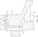
- FIG. 3 shows an alternate seal system 200 configuration, otherwise similar to FIG. 1 with several exceptions.
- a first exception is that the cooling channel 130 extends radially outward to a plenum 220 ( FIG. 3A ).
- the plenum 220 is defined by the combination of: a further annular channel in a first seat piece 212; and a second piece 222 encircling and attached to the first piece.
- the exemplary second piece 222 is formed as an annular sleeve having a circumferential array of apertures 224 extending between an inner diameter (ID) surface 226 and an outer diameter (OD) surface 228.
- the ID surface is engaged to the OD surface of the first seat piece 212 fore and aft of the plenum 220 (e.g., via interference fit or a braze joint).
- Alternative configurations may have the second piece 222 as nondestructively removable from the first piece such as via a retaining clip or wire (e.g. snap ring). Similarly, in such removable configurations, separate seals may be provided between the pieces (e.g., O-rings).
- the apertures 224 are axially offset from the outer diameter opening of the channel 130 to the plenum 220.
- An exemplary number of apertures 224 is 10 to 100, more particularly 20 to 80 or 25 to 55 in seal sizes used on gas turbine engines.
- the plenum 220 and apertures 224 may provide one or more of several functions.
- the apertures may provide a metering function (metering/restricting discharge flows 266) helping ensure the flow has sufficient residence time in the channel 130 to not separate from the face 140 and to provide sufficient cooling. Additionally, residence time in the plenum 220 may further cool the first seat piece 212 to maximize the cooling.
- Exemplary offset S 3 (measured center-to-center) is 0.00 inches to 0.50 inches (0.0 mm to 12.7 mm), more particularly, 0.00 inches to 0.30 inches (0.0 mm to 7.6 mm) or, for non-zero values 0.10 inch to 0.30 inch (2.5 mm to 7.6 mm) or 0.10 inch to 0.50 inch (2.5 mm to 12.7 mm).
- FIG. 3 A further difference between the FIG. 3 and FIG. 1 systems is the FIG. 3 presence of an integral weir formed in the first piece. This may be more representative of conventional weirs.
- Additional variations include seals where the oil is not delivered from a spray nozzle, but instead passes outward from a plenum (e.g., as in the '459 and '978 patents above) or via other means.
- first, second, and the like in the following claims is for differentiation within the claim only and does not necessarily indicate relative or absolute importance or temporal order. Similarly, the identification in a claim of one element as “first” (or the like) does not preclude such "first” element from identifying an element that is referred to as “second” (or the like) in another claim or in the description.
Landscapes
- Engineering & Computer Science (AREA)
- General Engineering & Computer Science (AREA)
- Mechanical Engineering (AREA)
- Chemical & Material Sciences (AREA)
- Combustion & Propulsion (AREA)
- Turbine Rotor Nozzle Sealing (AREA)
Claims (15)
- Dichtungssystem (200), umfassend:ein erstes Element (102);eine Dichtung (104), die durch das erste Element (102) getragen wird und eine Dichtungsfläche aufweist; undein zweites Element, das relativ zu dem ersten Element (102) um eine Achse (500) drehbar ist und Folgendes aufweist:einen Sitz (212), wobei der Sitz (212) eine Dichtungsfläche aufweist, die in gleitendem Dichteingriff mit der Dichtungsfläche steht; undeine Umfangsanordnung von Durchgangsschenkeln,wobei das zweite Element ferner Folgendes umfasst:einen axial von der Sitzfläche beabstandeten ringförmigen Kanal (130), wobei die Durchgangsschenkel mit dem ringförmigen Kanal (130) verbunden sind,wobei:sich die Durchgangsschenkel und der ringförmige Kanal (130) in einem ersten Teil (212) befinden; undein zweiter Teil (222) das erste Teil (212) umgibt und daran befestigt ist;dadurch gekennzeichnet, dassdas zweite Teil (222) eine Umfangsanordnung von Öffnungen (224) aufweist und mit dem ersten Teil (212) zusammenwirkt, um eine sich von dem ringförmigen Kanal (130) erstreckende Luftkammer (220) zu definieren.
- Dichtungssystem (200) nach Anspruch 1, wobei:
die Dichtung (104) eine Kohlenstoffdichtung (104) ist. - Dichtungssystem (200) nach Anspruch 1 oder 2, wobei:der Sitz (212) Stahl ist; undder Sitz (212) und die Dichtung (104) vollständig ringförmig sind.
- Dichtungssystem (200) nach einem der vorhergehenden Ansprüche, wobei:
der ringförmige Kanal (130) entlang einer radialen Öffnungsweite der Sitzfläche um 1,0 mm bis 6,0 mm von der Sitzfläche beabstandet ist. - Dichtungssystem (200) nach einem der vorhergehenden Ansprüche, wobei:
der ringförmige Kanal (130) einen Berührungsbereich der Sitzfläche und der Dichtfläche radial vollständig überlappt. - Dichtungssystem (200) nach einem der vorhergehenden Ansprüche, wobei:
der ringförmige Kanal (130) eine erste Oberfläche (140) aufweist, die von der Sitzfläche axial in einer radial nach außen gerichteten Richtung divergiert, optional um 2,0° bis 8,0°. - Dichtungssystem (100; 200) nach Anspruch 6, wobei:
der ringförmige Kanal (130) eine zweite Oberfläche (142) aufweist, die von der ersten Oberfläche (140) axial in der radial nach außen gerichteten Richtung divergiert, optional um 1,0° bis 10,0°. - Dichtungssystem (200) nach einem der vorhergehenden Ansprüche, wobei:
das zweite Teil (222) durch Presspassung oder Löten an dem ersten Teil (212) angebracht ist. - Dichtungssystem (200) nach einem der vorhergehenden Ansprüche, wobei:
die Umfangsanordnung von Öffnungen (224) des zweiten Teils (222) axial von dem ringförmigen Kanal (130) in einer von der Dichtung (104) wegführenden Richtung versetzt ist. - Dichtungssystem (200) nach Anspruch 9, wobei:
der axiale Versatz (S3) der Umfangsanordnung von Öffnungen (224) von der Außendurchmesseröffnung des ringförmigen Kanals (130) an der Luftkammer (220), gemessen von Mitte zu Mitte, 2,5 mm bis 12,7 mm beträgt. - Dichtungssystem (200) nach einem der vorherigen Ansprüche, ferner umfassend:
eine Ölquelle, die zum Einleiten von Öl (160, 167) in die Durchgangsschenkel positioniert ist. - Dichtungssystem (200) nach einem der vorhergehenden Ansprüche, das eine Trockenflächendichtung ist.
- Gasturbinentriebwerk (20), beinhaltend das Dichtungssystem (200) nach einem der vorhergehenden Ansprüche, wobei:
das zweite Element eine Welle (24, 25, 81) ist. - Verfahren zum Verwenden des Dichtungssystems (200) nach einem der vorhergehenden Ansprüche, wobei das Verfahren Folgendes umfasst:relatives Drehen des zweiten Elements zu dem ersten Element (102) um die Achse (500);wobei die Drehung zentrifugal einen Ölstrom durch die Durchgangsschenkel und von den Durchgangsschenkeln durch den ringförmigen Kanal (130) treibt; unddas durch den ringförmigen Kanal (130) strömende Öl die Sitzfläche kühlt.
- Verfahren nach Anspruch 14, ferner umfassend Versprühen des Öls (167) aus einer Düse, wobei das versprühte Öl (167) optional zentrifugal in einem oder dem radial nach außen geschlossenen Sammelkanal gesammelt wird, von dem sich die Durchgangsschenkel erstrecken.
Applications Claiming Priority (2)
| Application Number | Priority Date | Filing Date | Title |
|---|---|---|---|
| US16/173,500 US11236636B2 (en) | 2018-10-29 | 2018-10-29 | Oil-cooled carbon seal |
| EP19206047.3A EP3647634B1 (de) | 2018-10-29 | 2019-10-29 | Ölgekühlte kohlenstoffdichtung |
Related Parent Applications (2)
| Application Number | Title | Priority Date | Filing Date |
|---|---|---|---|
| EP19206047.3A Division EP3647634B1 (de) | 2018-10-29 | 2019-10-29 | Ölgekühlte kohlenstoffdichtung |
| EP19206047.3A Division-Into EP3647634B1 (de) | 2018-10-29 | 2019-10-29 | Ölgekühlte kohlenstoffdichtung |
Publications (2)
| Publication Number | Publication Date |
|---|---|
| EP4160059A1 EP4160059A1 (de) | 2023-04-05 |
| EP4160059B1 true EP4160059B1 (de) | 2025-04-09 |
Family
ID=68392828
Family Applications (2)
| Application Number | Title | Priority Date | Filing Date |
|---|---|---|---|
| EP19206047.3A Active EP3647634B1 (de) | 2018-10-29 | 2019-10-29 | Ölgekühlte kohlenstoffdichtung |
| EP22209749.5A Active EP4160059B1 (de) | 2018-10-29 | 2019-10-29 | Ölgekühlte kohlenstoffdichtung |
Family Applications Before (1)
| Application Number | Title | Priority Date | Filing Date |
|---|---|---|---|
| EP19206047.3A Active EP3647634B1 (de) | 2018-10-29 | 2019-10-29 | Ölgekühlte kohlenstoffdichtung |
Country Status (2)
| Country | Link |
|---|---|
| US (1) | US11236636B2 (de) |
| EP (2) | EP3647634B1 (de) |
Families Citing this family (12)
| Publication number | Priority date | Publication date | Assignee | Title |
|---|---|---|---|---|
| US11753964B2 (en) | 2018-10-29 | 2023-09-12 | Rtx Corporation | Oil-cooled carbon seal |
| US10975723B2 (en) | 2019-02-26 | 2021-04-13 | Raytheon Technologies Corporation | Gas turbine engine including seal plate providing increased cooling adjacent contact area |
| US11193389B2 (en) * | 2019-10-18 | 2021-12-07 | Raytheon Technologies Corporation | Fluid cooled seal land for rotational equipment seal assembly |
| US11441448B2 (en) | 2020-02-13 | 2022-09-13 | Raytheon Technologies Corporation | Impingement cooled rotating seal |
| US11339719B2 (en) * | 2020-04-27 | 2022-05-24 | Raytheon Technologies Corporation | Fluid delivery system for rotational equipment |
| US11371374B2 (en) | 2020-07-22 | 2022-06-28 | Raytheon Technologies Corporation | Seal runner flow damper |
| GB2601629A (en) * | 2020-11-13 | 2022-06-08 | Eaton Intelligent Power Ltd | Additive manufactured seal rotor; and method |
| EP4036376B1 (de) * | 2020-12-15 | 2023-11-15 | RTX Corporation | Ölgekühlte kohlenstoffdichtung |
| EP4202263A1 (de) * | 2021-12-10 | 2023-06-28 | Raytheon Technologies Corporation | An einen dichtungsträger gebondetes dichtelement für einen turbinenmotor |
| US12241379B2 (en) * | 2022-08-03 | 2025-03-04 | General Electric Company | Cooling system for seal assemblies |
| US12000299B1 (en) | 2023-08-25 | 2024-06-04 | Rolls-Royce Corporation | Centrifugally operated oil shield for lubrication flow control |
| CN119196312A (zh) * | 2024-10-16 | 2024-12-27 | 中国船舶集团有限公司第七〇四研究所 | 一种高线速度密封装置 |
Family Cites Families (16)
| Publication number | Priority date | Publication date | Assignee | Title |
|---|---|---|---|---|
| US3578343A (en) * | 1969-04-24 | 1971-05-11 | Koppers Co Inc | Annular shoulder assembly for a rotating seal |
| US4314705A (en) * | 1979-05-23 | 1982-02-09 | Ishikawajima-Harima Jukogyo Kabushiki Kaisha | Oil seal device |
| US4406459A (en) * | 1982-06-18 | 1983-09-27 | United Technologies Corporation | Oil weepage return for carbon seal plates |
| US4928978A (en) * | 1988-04-07 | 1990-05-29 | United Technologies Corporation | Rotating shaft seal |
| US6099243A (en) * | 1999-01-29 | 2000-08-08 | Caterpillar Inc. | Centrifugal pump with seal cooling and debris flushing arrangement |
| US7883093B2 (en) * | 2004-07-02 | 2011-02-08 | Nippon Pillar Packing Co., Ltd. | Mechanical seal |
| US7861530B2 (en) | 2007-03-30 | 2011-01-04 | Pratt & Whitney Canada Corp. | Combustor floating collar with louver |
| US20140140824A1 (en) * | 2012-10-26 | 2014-05-22 | United Technologies Corporation | Oil system bearing compartment architecture for gas turbine engine |
| EP3066368B1 (de) * | 2013-11-06 | 2019-04-17 | United Technologies Corporation | Axiale schaufeldichtungsplatte |
| US9719373B2 (en) | 2013-12-03 | 2017-08-01 | United Technologies Corporation | Slotted distribution sleeve for a seal plate |
| US9683458B2 (en) * | 2015-08-20 | 2017-06-20 | Pratt & Whitney Canada Corp. | Oil scupper system for bearing housing of gas turbine engine |
| US20180045316A1 (en) * | 2016-08-09 | 2018-02-15 | United Technologies Corporation | Hydrodynamic seal seat cooling features |
| US20180087404A1 (en) * | 2016-09-23 | 2018-03-29 | Rolls-Royce Corporation | Oil distributor |
| US10422245B2 (en) | 2017-03-28 | 2019-09-24 | United Technologies Corporation | Seal element with internal lubricant plenum for rotational equipment |
| US10655679B2 (en) | 2017-04-07 | 2020-05-19 | United Technologies Corporation | Oil control for seal plates |
| US11209086B2 (en) * | 2018-10-29 | 2021-12-28 | Raytheon Technologies Corporation | Wet-face/dry-face seal and methods of operation |
-
2018
- 2018-10-29 US US16/173,500 patent/US11236636B2/en active Active
-
2019
- 2019-10-29 EP EP19206047.3A patent/EP3647634B1/de active Active
- 2019-10-29 EP EP22209749.5A patent/EP4160059B1/de active Active
Also Published As
| Publication number | Publication date |
|---|---|
| EP4160059A1 (de) | 2023-04-05 |
| EP3647634B1 (de) | 2024-04-24 |
| US11236636B2 (en) | 2022-02-01 |
| US20200131936A1 (en) | 2020-04-30 |
| EP3647634A1 (de) | 2020-05-06 |
Similar Documents
| Publication | Publication Date | Title |
|---|---|---|
| EP3647634B1 (de) | Ölgekühlte kohlenstoffdichtung | |
| EP3647633B1 (de) | Nassflächen-/trockenflächendichtung und verfahren zum betrieb | |
| CA2928544C (en) | Seal and bearing assembly for a gas turbine engine and method of assembling same | |
| CA2928546C (en) | Internally cooled seal slider and method for cooling a seal slider of a gas turbine engine | |
| EP3382240B1 (de) | Dichtungselement mit internem schmiermittelplenum für eine rotationsausrüstung | |
| US6286303B1 (en) | Impingement cooled foil bearings in a gas turbine engine | |
| US9546560B2 (en) | Compact double grounded mechanical carbon seal | |
| EP3712469B1 (de) | Dichtungsplattenschmiermittelschleuderscheibe | |
| EP3318722B1 (de) | Dichtungsanordnung für ein drehbares bestandteil | |
| EP3904731B1 (de) | Poröses dichtungselement mit internem fluidkanal | |
| EP3382279B1 (de) | Zwischenscheibe für brennkammeranordnung | |
| EP3722568B1 (de) | Lagerraumdichtungskonfiguration für einen gasturbinenmotor | |
| EP3904644B1 (de) | Flüssigkeitsabgabesystem für rotationsgeräte | |
| EP3954879B1 (de) | Schöpfanordnung für rotierende ausrüstung | |
| EP3708794B1 (de) | Ölzufuhrsystem mit zwei radialschaufeln | |
| US12385419B2 (en) | Oil-cooled carbon seal | |
| EP4299881B1 (de) | Schaufelanordnung für rotierende ausrüstung | |
| EP4036376B1 (de) | Ölgekühlte kohlenstoffdichtung | |
| EP3712471B1 (de) | Zweiteiliger sitz für berührungsdichtung | |
| EP4491914A1 (de) | Dichtungsträger mit wälzkörperführungsschienenkontakt | |
| EP3783203B1 (de) | Bauteil eines gasturbinentriebwerks umfassend eine radialdichtungsanordnung mit sich axial erstreckendem ölgekühltem dichtungsläufer |
Legal Events
| Date | Code | Title | Description |
|---|---|---|---|
| PUAI | Public reference made under article 153(3) epc to a published international application that has entered the european phase |
Free format text: ORIGINAL CODE: 0009012 |
|
| STAA | Information on the status of an ep patent application or granted ep patent |
Free format text: STATUS: THE APPLICATION HAS BEEN PUBLISHED |
|
| AC | Divisional application: reference to earlier application |
Ref document number: 3647634 Country of ref document: EP Kind code of ref document: P |
|
| AK | Designated contracting states |
Kind code of ref document: A1 Designated state(s): AL AT BE BG CH CY CZ DE DK EE ES FI FR GB GR HR HU IE IS IT LI LT LU LV MC MK MT NL NO PL PT RO RS SE SI SK SM TR |
|
| STAA | Information on the status of an ep patent application or granted ep patent |
Free format text: STATUS: REQUEST FOR EXAMINATION WAS MADE |
|
| RAP3 | Party data changed (applicant data changed or rights of an application transferred) |
Owner name: RTX CORPORATION |
|
| 17P | Request for examination filed |
Effective date: 20231005 |
|
| RBV | Designated contracting states (corrected) |
Designated state(s): AL AT BE BG CH CY CZ DE DK EE ES FI FR GB GR HR HU IE IS IT LI LT LU LV MC MK MT NL NO PL PT RO RS SE SI SK SM TR |
|
| GRAP | Despatch of communication of intention to grant a patent |
Free format text: ORIGINAL CODE: EPIDOSNIGR1 |
|
| STAA | Information on the status of an ep patent application or granted ep patent |
Free format text: STATUS: GRANT OF PATENT IS INTENDED |
|
| RIC1 | Information provided on ipc code assigned before grant |
Ipc: F01D 25/18 20060101ALI20241021BHEP Ipc: F01D 25/12 20060101ALI20241021BHEP Ipc: F01D 11/00 20060101ALI20241021BHEP Ipc: F16J 15/34 20060101AFI20241021BHEP |
|
| INTG | Intention to grant announced |
Effective date: 20241104 |
|
| GRAS | Grant fee paid |
Free format text: ORIGINAL CODE: EPIDOSNIGR3 |
|
| GRAA | (expected) grant |
Free format text: ORIGINAL CODE: 0009210 |
|
| STAA | Information on the status of an ep patent application or granted ep patent |
Free format text: STATUS: THE PATENT HAS BEEN GRANTED |
|
| AC | Divisional application: reference to earlier application |
Ref document number: 3647634 Country of ref document: EP Kind code of ref document: P |
|
| AK | Designated contracting states |
Kind code of ref document: B1 Designated state(s): AL AT BE BG CH CY CZ DE DK EE ES FI FR GB GR HR HU IE IS IT LI LT LU LV MC MK MT NL NO PL PT RO RS SE SI SK SM TR |
|
| REG | Reference to a national code |
Ref country code: GB Ref legal event code: FG4D |
|
| REG | Reference to a national code |
Ref country code: CH Ref legal event code: EP |
|
| REG | Reference to a national code |
Ref country code: DE Ref legal event code: R096 Ref document number: 602019068602 Country of ref document: DE |
|
| REG | Reference to a national code |
Ref country code: IE Ref legal event code: FG4D |
|
| PG25 | Lapsed in a contracting state [announced via postgrant information from national office to epo] |
Ref country code: NL Free format text: LAPSE BECAUSE OF FAILURE TO SUBMIT A TRANSLATION OF THE DESCRIPTION OR TO PAY THE FEE WITHIN THE PRESCRIBED TIME-LIMIT Effective date: 20250409 |
|
| REG | Reference to a national code |
Ref country code: AT Ref legal event code: MK05 Ref document number: 1783763 Country of ref document: AT Kind code of ref document: T Effective date: 20250409 |
|
| PG25 | Lapsed in a contracting state [announced via postgrant information from national office to epo] |
Ref country code: FI Free format text: LAPSE BECAUSE OF FAILURE TO SUBMIT A TRANSLATION OF THE DESCRIPTION OR TO PAY THE FEE WITHIN THE PRESCRIBED TIME-LIMIT Effective date: 20250409 Ref country code: PT Free format text: LAPSE BECAUSE OF FAILURE TO SUBMIT A TRANSLATION OF THE DESCRIPTION OR TO PAY THE FEE WITHIN THE PRESCRIBED TIME-LIMIT Effective date: 20250811 Ref country code: ES Free format text: LAPSE BECAUSE OF FAILURE TO SUBMIT A TRANSLATION OF THE DESCRIPTION OR TO PAY THE FEE WITHIN THE PRESCRIBED TIME-LIMIT Effective date: 20250409 |
|
| REG | Reference to a national code |
Ref country code: LT Ref legal event code: MG9D |
|
| PG25 | Lapsed in a contracting state [announced via postgrant information from national office to epo] |
Ref country code: NO Free format text: LAPSE BECAUSE OF FAILURE TO SUBMIT A TRANSLATION OF THE DESCRIPTION OR TO PAY THE FEE WITHIN THE PRESCRIBED TIME-LIMIT Effective date: 20250709 Ref country code: GR Free format text: LAPSE BECAUSE OF FAILURE TO SUBMIT A TRANSLATION OF THE DESCRIPTION OR TO PAY THE FEE WITHIN THE PRESCRIBED TIME-LIMIT Effective date: 20250710 |
|
| PG25 | Lapsed in a contracting state [announced via postgrant information from national office to epo] |
Ref country code: PL Free format text: LAPSE BECAUSE OF FAILURE TO SUBMIT A TRANSLATION OF THE DESCRIPTION OR TO PAY THE FEE WITHIN THE PRESCRIBED TIME-LIMIT Effective date: 20250409 |
|
| PG25 | Lapsed in a contracting state [announced via postgrant information from national office to epo] |
Ref country code: BG Free format text: LAPSE BECAUSE OF FAILURE TO SUBMIT A TRANSLATION OF THE DESCRIPTION OR TO PAY THE FEE WITHIN THE PRESCRIBED TIME-LIMIT Effective date: 20250409 |
|
| PGFP | Annual fee paid to national office [announced via postgrant information from national office to epo] |
Ref country code: GB Payment date: 20250923 Year of fee payment: 7 |
|
| PG25 | Lapsed in a contracting state [announced via postgrant information from national office to epo] |
Ref country code: HR Free format text: LAPSE BECAUSE OF FAILURE TO SUBMIT A TRANSLATION OF THE DESCRIPTION OR TO PAY THE FEE WITHIN THE PRESCRIBED TIME-LIMIT Effective date: 20250409 |
|
| PG25 | Lapsed in a contracting state [announced via postgrant information from national office to epo] |
Ref country code: AT Free format text: LAPSE BECAUSE OF FAILURE TO SUBMIT A TRANSLATION OF THE DESCRIPTION OR TO PAY THE FEE WITHIN THE PRESCRIBED TIME-LIMIT Effective date: 20250409 |
|
| PGFP | Annual fee paid to national office [announced via postgrant information from national office to epo] |
Ref country code: FR Payment date: 20250924 Year of fee payment: 7 |
|
| PG25 | Lapsed in a contracting state [announced via postgrant information from national office to epo] |
Ref country code: RS Free format text: LAPSE BECAUSE OF FAILURE TO SUBMIT A TRANSLATION OF THE DESCRIPTION OR TO PAY THE FEE WITHIN THE PRESCRIBED TIME-LIMIT Effective date: 20250709 |
|
| PG25 | Lapsed in a contracting state [announced via postgrant information from national office to epo] |
Ref country code: IS Free format text: LAPSE BECAUSE OF FAILURE TO SUBMIT A TRANSLATION OF THE DESCRIPTION OR TO PAY THE FEE WITHIN THE PRESCRIBED TIME-LIMIT Effective date: 20250809 |
|
| PG25 | Lapsed in a contracting state [announced via postgrant information from national office to epo] |
Ref country code: LV Free format text: LAPSE BECAUSE OF FAILURE TO SUBMIT A TRANSLATION OF THE DESCRIPTION OR TO PAY THE FEE WITHIN THE PRESCRIBED TIME-LIMIT Effective date: 20250409 |
|
| PGFP | Annual fee paid to national office [announced via postgrant information from national office to epo] |
Ref country code: DE Payment date: 20250923 Year of fee payment: 7 |
|
| REG | Reference to a national code |
Ref country code: DE Ref legal event code: R097 Ref document number: 602019068602 Country of ref document: DE |
|
| PG25 | Lapsed in a contracting state [announced via postgrant information from national office to epo] |
Ref country code: DK Free format text: LAPSE BECAUSE OF FAILURE TO SUBMIT A TRANSLATION OF THE DESCRIPTION OR TO PAY THE FEE WITHIN THE PRESCRIBED TIME-LIMIT Effective date: 20250409 Ref country code: SM Free format text: LAPSE BECAUSE OF FAILURE TO SUBMIT A TRANSLATION OF THE DESCRIPTION OR TO PAY THE FEE WITHIN THE PRESCRIBED TIME-LIMIT Effective date: 20250409 |
|
| PG25 | Lapsed in a contracting state [announced via postgrant information from national office to epo] |
Ref country code: CZ Free format text: LAPSE BECAUSE OF FAILURE TO SUBMIT A TRANSLATION OF THE DESCRIPTION OR TO PAY THE FEE WITHIN THE PRESCRIBED TIME-LIMIT Effective date: 20250409 |
|
| PG25 | Lapsed in a contracting state [announced via postgrant information from national office to epo] |
Ref country code: EE Free format text: LAPSE BECAUSE OF FAILURE TO SUBMIT A TRANSLATION OF THE DESCRIPTION OR TO PAY THE FEE WITHIN THE PRESCRIBED TIME-LIMIT Effective date: 20250409 |
|
| PG25 | Lapsed in a contracting state [announced via postgrant information from national office to epo] |
Ref country code: SK Free format text: LAPSE BECAUSE OF FAILURE TO SUBMIT A TRANSLATION OF THE DESCRIPTION OR TO PAY THE FEE WITHIN THE PRESCRIBED TIME-LIMIT Effective date: 20250409 |
|
| PG25 | Lapsed in a contracting state [announced via postgrant information from national office to epo] |
Ref country code: IT Free format text: LAPSE BECAUSE OF FAILURE TO SUBMIT A TRANSLATION OF THE DESCRIPTION OR TO PAY THE FEE WITHIN THE PRESCRIBED TIME-LIMIT Effective date: 20250409 |
|
| PG25 | Lapsed in a contracting state [announced via postgrant information from national office to epo] |
Ref country code: RO Free format text: LAPSE BECAUSE OF FAILURE TO SUBMIT A TRANSLATION OF THE DESCRIPTION OR TO PAY THE FEE WITHIN THE PRESCRIBED TIME-LIMIT Effective date: 20250409 |
|
| PLBE | No opposition filed within time limit |
Free format text: ORIGINAL CODE: 0009261 |
|
| STAA | Information on the status of an ep patent application or granted ep patent |
Free format text: STATUS: NO OPPOSITION FILED WITHIN TIME LIMIT |
|
| REG | Reference to a national code |
Ref country code: CH Ref legal event code: L10 Free format text: ST27 STATUS EVENT CODE: U-0-0-L10-L00 (AS PROVIDED BY THE NATIONAL OFFICE) Effective date: 20260218 |
|
| 26N | No opposition filed |
Effective date: 20260112 |