EP4160043A1 - Spring, spring assembly and brake pad, caliper body assembly - Google Patents
Spring, spring assembly and brake pad, caliper body assembly Download PDFInfo
- Publication number
- EP4160043A1 EP4160043A1 EP22198934.6A EP22198934A EP4160043A1 EP 4160043 A1 EP4160043 A1 EP 4160043A1 EP 22198934 A EP22198934 A EP 22198934A EP 4160043 A1 EP4160043 A1 EP 4160043A1
- Authority
- EP
- European Patent Office
- Prior art keywords
- spring
- caliper
- thrust
- backing
- coupling
- Prior art date
- Legal status (The legal status is an assumption and is not a legal conclusion. Google has not performed a legal analysis and makes no representation as to the accuracy of the status listed.)
- Granted
Links
Images





Classifications
-
- F—MECHANICAL ENGINEERING; LIGHTING; HEATING; WEAPONS; BLASTING
- F16—ENGINEERING ELEMENTS AND UNITS; GENERAL MEASURES FOR PRODUCING AND MAINTAINING EFFECTIVE FUNCTIONING OF MACHINES OR INSTALLATIONS; THERMAL INSULATION IN GENERAL
- F16D—COUPLINGS FOR TRANSMITTING ROTATION; CLUTCHES; BRAKES
- F16D65/00—Parts or details
- F16D65/02—Braking members; Mounting thereof
- F16D65/04—Bands, shoes or pads; Pivots or supporting members therefor
- F16D65/092—Bands, shoes or pads; Pivots or supporting members therefor for axially-engaging brakes, e.g. disc brakes
- F16D65/095—Pivots or supporting members therefor
- F16D65/097—Resilient means interposed between pads and supporting members or other brake parts
- F16D65/0973—Resilient means interposed between pads and supporting members or other brake parts not subjected to brake forces
- F16D65/0974—Resilient means interposed between pads and supporting members or other brake parts not subjected to brake forces acting on or in the vicinity of the pad rim in a direction substantially transverse to the brake disc axis
- F16D65/0977—Springs made from sheet metal
-
- F—MECHANICAL ENGINEERING; LIGHTING; HEATING; WEAPONS; BLASTING
- F16—ENGINEERING ELEMENTS AND UNITS; GENERAL MEASURES FOR PRODUCING AND MAINTAINING EFFECTIVE FUNCTIONING OF MACHINES OR INSTALLATIONS; THERMAL INSULATION IN GENERAL
- F16D—COUPLINGS FOR TRANSMITTING ROTATION; CLUTCHES; BRAKES
- F16D55/00—Brakes with substantially-radial braking surfaces pressed together in axial direction, e.g. disc brakes
- F16D55/02—Brakes with substantially-radial braking surfaces pressed together in axial direction, e.g. disc brakes with axially-movable discs or pads pressed against axially-located rotating members
- F16D55/22—Brakes with substantially-radial braking surfaces pressed together in axial direction, e.g. disc brakes with axially-movable discs or pads pressed against axially-located rotating members by clamping an axially-located rotating disc between movable braking members, e.g. movable brake discs or brake pads
- F16D55/224—Brakes with substantially-radial braking surfaces pressed together in axial direction, e.g. disc brakes with axially-movable discs or pads pressed against axially-located rotating members by clamping an axially-located rotating disc between movable braking members, e.g. movable brake discs or brake pads with a common actuating member for the braking members
- F16D55/225—Brakes with substantially-radial braking surfaces pressed together in axial direction, e.g. disc brakes with axially-movable discs or pads pressed against axially-located rotating members by clamping an axially-located rotating disc between movable braking members, e.g. movable brake discs or brake pads with a common actuating member for the braking members the braking members being brake pads
- F16D55/226—Brakes with substantially-radial braking surfaces pressed together in axial direction, e.g. disc brakes with axially-movable discs or pads pressed against axially-located rotating members by clamping an axially-located rotating disc between movable braking members, e.g. movable brake discs or brake pads with a common actuating member for the braking members the braking members being brake pads in which the common actuating member is moved axially, e.g. floating caliper disc brakes
- F16D55/2265—Brakes with substantially-radial braking surfaces pressed together in axial direction, e.g. disc brakes with axially-movable discs or pads pressed against axially-located rotating members by clamping an axially-located rotating disc between movable braking members, e.g. movable brake discs or brake pads with a common actuating member for the braking members the braking members being brake pads in which the common actuating member is moved axially, e.g. floating caliper disc brakes the axial movement being guided by one or more pins engaging bores in the brake support or the brake housing
-
- F—MECHANICAL ENGINEERING; LIGHTING; HEATING; WEAPONS; BLASTING
- F16—ENGINEERING ELEMENTS AND UNITS; GENERAL MEASURES FOR PRODUCING AND MAINTAINING EFFECTIVE FUNCTIONING OF MACHINES OR INSTALLATIONS; THERMAL INSULATION IN GENERAL
- F16D—COUPLINGS FOR TRANSMITTING ROTATION; CLUTCHES; BRAKES
- F16D55/00—Brakes with substantially-radial braking surfaces pressed together in axial direction, e.g. disc brakes
- F16D55/02—Brakes with substantially-radial braking surfaces pressed together in axial direction, e.g. disc brakes with axially-movable discs or pads pressed against axially-located rotating members
- F16D55/22—Brakes with substantially-radial braking surfaces pressed together in axial direction, e.g. disc brakes with axially-movable discs or pads pressed against axially-located rotating members by clamping an axially-located rotating disc between movable braking members, e.g. movable brake discs or brake pads
- F16D55/228—Brakes with substantially-radial braking surfaces pressed together in axial direction, e.g. disc brakes with axially-movable discs or pads pressed against axially-located rotating members by clamping an axially-located rotating disc between movable braking members, e.g. movable brake discs or brake pads with a separate actuating member for each side
-
- F—MECHANICAL ENGINEERING; LIGHTING; HEATING; WEAPONS; BLASTING
- F16—ENGINEERING ELEMENTS AND UNITS; GENERAL MEASURES FOR PRODUCING AND MAINTAINING EFFECTIVE FUNCTIONING OF MACHINES OR INSTALLATIONS; THERMAL INSULATION IN GENERAL
- F16D—COUPLINGS FOR TRANSMITTING ROTATION; CLUTCHES; BRAKES
- F16D65/00—Parts or details
- F16D65/005—Components of axially engaging brakes not otherwise provided for
- F16D65/0068—Brake calipers
-
- F—MECHANICAL ENGINEERING; LIGHTING; HEATING; WEAPONS; BLASTING
- F16—ENGINEERING ELEMENTS AND UNITS; GENERAL MEASURES FOR PRODUCING AND MAINTAINING EFFECTIVE FUNCTIONING OF MACHINES OR INSTALLATIONS; THERMAL INSULATION IN GENERAL
- F16D—COUPLINGS FOR TRANSMITTING ROTATION; CLUTCHES; BRAKES
- F16D65/00—Parts or details
- F16D65/02—Braking members; Mounting thereof
- F16D65/04—Bands, shoes or pads; Pivots or supporting members therefor
- F16D65/092—Bands, shoes or pads; Pivots or supporting members therefor for axially-engaging brakes, e.g. disc brakes
- F16D65/095—Pivots or supporting members therefor
- F16D65/097—Resilient means interposed between pads and supporting members or other brake parts
- F16D65/0972—Resilient means interposed between pads and supporting members or other brake parts transmitting brake reaction force, e.g. elements interposed between torque support plate and pad
-
- F—MECHANICAL ENGINEERING; LIGHTING; HEATING; WEAPONS; BLASTING
- F16—ENGINEERING ELEMENTS AND UNITS; GENERAL MEASURES FOR PRODUCING AND MAINTAINING EFFECTIVE FUNCTIONING OF MACHINES OR INSTALLATIONS; THERMAL INSULATION IN GENERAL
- F16D—COUPLINGS FOR TRANSMITTING ROTATION; CLUTCHES; BRAKES
- F16D55/00—Brakes with substantially-radial braking surfaces pressed together in axial direction, e.g. disc brakes
- F16D2055/0004—Parts or details of disc brakes
- F16D2055/0016—Brake calipers
-
- F—MECHANICAL ENGINEERING; LIGHTING; HEATING; WEAPONS; BLASTING
- F16—ENGINEERING ELEMENTS AND UNITS; GENERAL MEASURES FOR PRODUCING AND MAINTAINING EFFECTIVE FUNCTIONING OF MACHINES OR INSTALLATIONS; THERMAL INSULATION IN GENERAL
- F16D—COUPLINGS FOR TRANSMITTING ROTATION; CLUTCHES; BRAKES
- F16D55/00—Brakes with substantially-radial braking surfaces pressed together in axial direction, e.g. disc brakes
- F16D2055/0004—Parts or details of disc brakes
- F16D2055/0016—Brake calipers
- F16D2055/0029—Retraction devices
-
- F—MECHANICAL ENGINEERING; LIGHTING; HEATING; WEAPONS; BLASTING
- F16—ENGINEERING ELEMENTS AND UNITS; GENERAL MEASURES FOR PRODUCING AND MAINTAINING EFFECTIVE FUNCTIONING OF MACHINES OR INSTALLATIONS; THERMAL INSULATION IN GENERAL
- F16D—COUPLINGS FOR TRANSMITTING ROTATION; CLUTCHES; BRAKES
- F16D55/00—Brakes with substantially-radial braking surfaces pressed together in axial direction, e.g. disc brakes
- F16D2055/0004—Parts or details of disc brakes
- F16D2055/007—Pins holding the braking members
-
- F—MECHANICAL ENGINEERING; LIGHTING; HEATING; WEAPONS; BLASTING
- F16—ENGINEERING ELEMENTS AND UNITS; GENERAL MEASURES FOR PRODUCING AND MAINTAINING EFFECTIVE FUNCTIONING OF MACHINES OR INSTALLATIONS; THERMAL INSULATION IN GENERAL
- F16D—COUPLINGS FOR TRANSMITTING ROTATION; CLUTCHES; BRAKES
- F16D2127/00—Auxiliary mechanisms
- F16D2127/02—Release mechanisms
-
- F—MECHANICAL ENGINEERING; LIGHTING; HEATING; WEAPONS; BLASTING
- F16—ENGINEERING ELEMENTS AND UNITS; GENERAL MEASURES FOR PRODUCING AND MAINTAINING EFFECTIVE FUNCTIONING OF MACHINES OR INSTALLATIONS; THERMAL INSULATION IN GENERAL
- F16D—COUPLINGS FOR TRANSMITTING ROTATION; CLUTCHES; BRAKES
- F16D65/00—Parts or details
- F16D65/005—Components of axially engaging brakes not otherwise provided for
- F16D65/0087—Brake housing guide members, e.g. caliper pins; Accessories therefor, e.g. dust boots
Definitions
- the present invention relates to a spring for a disc brake braking device, a spring assembly and brake pad, and a brake caliper assembly.
- the brake caliper is generally arranged straddling the external peripheral margin of a brake disc, adapted to rotate about a rotation axis (X-X) defining an axial direction (A-A).
- a radial direction (R-R) substantially orthogonal to said axial direction (A-A)
- a circumferential direction (C-C) orthogonal to both said axial direction (A-A) and said radial direction (R-R)
- a tangential direction (T-T) locally, or rather punctually, i.e., in an intersection point of an axial and radial direction, orthogonal to both said axial direction (A-A) and said a radial direction (R-R).
- disc brake discs comprise a bell adapted to associate the disc with a hub of a vehicle, from which an annular portion, referred to as a braking band, extends, which is intended to cooperate with brake pads of a caliper.
- Disc brake springs which consist of a central portion and two end portions, in which the end portions rest against the pads to stress the pads elastically away from each other to ensure a separation of the pads from the brake disc after each braking operation.
- the known springs are kept in their operating position by fixing the central portion of the springs to the caliper.
- the springs of the prior art generally comprise one or more connection appendages, formed at the central portion of the expansion spring, adapted to connect the springs to the caliper at coupling portions formed on the caliper.
- said coupling portions are made on the caliper body at least one connection bridge, made by casting with the caliper body, arranged straddling the brake disc and which connects a first elongated wheel side portion and a second elongated portion of the caliper body.
- document DE102017204696 shows a spring solution which includes only one connection appendage, which can be fixed to a side connection bridge of the caliper body
- documents WO2019/243958 and WO2020/128710 show spring solutions which include, in some embodiments, two connection appendages, which can be fixed to a side connection bridge and to a central connection bridge of the caliper body, respectively.
- These solutions involve connecting the spring to a side bridge of the caliper body, which allows a simple attachment to the caliper body and the pad.
- said solutions teach the use of at least one pair of springs to allow a balanced movement of at least one pad away from the brake disc, i.e., at least one first spring coupled to at least one first side bridge and a second spring coupled to at least one second side bridge, lengthening the time required for assembly and proper positioning of the springs on the caliper body.
- the anchoring portions of the spring connected to the connection bridges made by casting with the caliper body when subjected to high external stresses, may come out of their coupling seat, jeopardizing the operation of the spring itself.
- the springs of the prior art usually abut against an apical portion of the pads and, consequently, transmit a direct distancing force to the pads at the top of the pads, top which is understood as the radially external edge relative to the rotation axis of the brake disc.
- the correct positioning between the disc brake components, in particular between the spring and the brake pads is entrusted to the friction forces which are generated by virtue of the elastic force, which can be generally broken down along the three spatial directions, which the spring applies as a result of its deformation on the support, i.e., the pad plate.
- the aim of the present invention is to provide a spring, which allows a simple, secure, and durable connection to a caliper body without a central connection bridge, in which the connection of the spring to the caliper body does not change even as a result of external stresses applied to the system.
- the desired requirements are achieved directly with the component concerned with the problem, i.e., the band spring, by virtue of a geometry such as to counteract the sliding force.
- the object of such a geometry is to minimize the sliding component generated by the external force while at the same time maximizing the other component, i.e., the contact force which generates a further increase in the friction force compared to the current condition.
- All the disclosed solutions have the advantage of not biasing the functionality of the spring pad assembly and of creating a progressively increasing gap with the support as the latter advances with pad wear.
- the suggested spring geometry does not affect the behavior of the spring itself because in working conditions the abutment portion never comes into contact with the support and on the contrary, tends to move away from it as wear advances. Indeed, the portion of the stop is used only during assembly to ensure that the spring is mounted correctly but then in operation must not interact with the support i.e., the plate not to risk biasing the functionality of the spring.
- a spring 1 for a caliper body 8 is shaped to be arranged straddling a brake disc 2 to apply an elastic action on at least one brake pad 3 to bias it away from said brake disc 2.
- Said brake disc 2 is adapted to rotate about a rotation axis X-X, which defines an axial direction A-A, parallel to said rotation axis X-X, a radial direction R-R, orthogonal to said rotation axis X-X, and a tangential direction T-T orthogonal both to said axial direction A-A and to said radial direction R-R.
- Said at least one brake pad 3 comprises a support plate 31, which supports friction material 32, said support plate 31 comprising a plate edge 33, which forms at least one first plate thrust portion 34 and at least one second plate thrust portion 36.
- Said band spring 1 comprises a band-shaped spring body 4.
- Said caliper body 8 comprises a first elongated element or wheel side elongated element 38, a second elongated element or opposite wheel side elongated element 39, a first side bridge 40 and a second side bridge 41 adapted to connect said first elongated element 38 to said second elongated element 39 straddling said brake disc 2 and leaving a central portion of said caliper body 8 free from a central connection bridge.
- Said spring 1 comprises a spring body 4.
- Said spring 1 comprises a first thrust portion 5 adapted to apply said elastic action on said first plate thrust portion 34 of said at least one brake pad 3, biasing said brake pad 3 at least away from said brake disc 2 in axial direction A-A and radial direction R-R.
- Said spring 1 comprises a second thrust portion 6 adapted to apply said elastic action on said second plate thrust portion 36 of said at least one brake pad 3, biasing said brake pad 3 at least away from said brake disc 2 in axial direction A-A and radial direction R-R.
- Said first thrust portion 5 and said second thrust portion 6 being diametrically opposed to apply said spring action in a balanced manner on said at least one brake pad.
- Said spring 1 comprises a first coupling portion 14 adapted to couple said spring with said first side bridge 40.
- Said spring 1 comprises a second coupling portion 15 adapted to couple said spring 1 with said second side bridge 41 on a tangentially opposite side with respect to said first coupling portion 14.
- Said spring 1 comprises a backing portion 7 adapted to abut against a caliper pin 16 planted in said caliper body 8 or a caliper tie-rod 17 screwed to said caliper body 8 avoiding coupling with said caliper pin 16 or said caliper tie-rod 17.
- said spring 1 comprises at least one concave spring portion 46 having a concavity facing towards said brake disc 2 so that at least said backing portion 7 is elastically movable in the radial direction R-R toward said brake disc 2 between a rest configuration and at least one work configuration, elastically stressing said first coupling portion 14 and said second coupling portion 15 along said tangential direction T-T in opposite directions.
- said backing portion 7 abuts against either said caliper pin 16 or said clamp tie-rod 17, stressing said first coupling portion 14 and said second coupling portion 15 against said first side bridge 40 and against said second side bridge 41, respectively.
- said spring 1 comprises a first spring arm 43 adapted to connect said backing portion 7 to said first coupling portion 14.
- said first spring arm 43 is either filiform or band-like.
- said spring 1 comprises a second spring arm 44 adapted to connect said backing portion 7 to said second coupling portion 15.
- said spring second arm 44 is either filiform or band-like.
- said first spring arm 43 and said second spring arm 44 diverge from said backing portion 7 along first opposite directions, which are inclined relative to said tangential direction T-T and relative to said radial direction R-R forming said at least one concave spring portion 46.
- said first spring arm 43 and said second spring arm 44 are arranged inclined relative to said axial direction A-A and also relative to said radial direction R-R.
- said spring 1 forms a first angle V1 between said first spring arm 43 and said axial direction A-A and an opposite first angle -V1 between said second spring arm 44 and said axial direction A-A.
- said spring 1 forms a second angle V2 between said first spring arm 43 and said radial direction R-R, and an opposite second angle -V2 between said second spring arm 44 and said radial direction R-R.
- said spring 1 is shaped so that, in said work configuration, said backing portion 7 is constantly elastically biased in a radial direction R-R abutting against said caliper pin 16 or said caliper tie-rod 17 and so that said first coupling portion 14 and said second coupling portion 15 are constantly elastically biased in a tangential direction T-T against said caliper body 8.
- the concavity of said at least one concave spring portion 46 decreases between said rest position and said work position.
- said spring 1 comprises a third spring arm 47 adapted to connect said first spring arm 43 to said first coupling portion 14.
- said third spring arm 47 is either filiform or band-like.
- said spring 1 comprises a fourth spring arm 48 adapted to connect said second spring arm 44 to said second coupling portion 15.
- said fourth spring arm 48 is either filiform or band-like.
- said third spring arm 47 and said fourth spring arm 48 extend along second opposite directions, which are inclined relative to said tangential direction T-T and to said radial direction R-R.
- At least said first spring arm 43 and said third spring arm 47 form a second convex spring portion 50 having concavity opposite to said at least one concave spring portion 46.
- At least said second spring arm 44 and said fourth arm 48 form a third convex spring portion 51 having concavity opposite to said at least one concave spring portion 46.
- the concavity of said second convex spring portion 50 and the concavity of said third convex spring portion 51 decrease between said rest position and said working position, biasing said first coupling portion 14 and said second coupling portion against said caliper body 8 from diametrically opposite sides.
- said backing portion 7 is folded in a U or a V forming a first spring convex spring portion 49 having concavity opposite to said at least one concave spring portion 46 adapted to abut against said caliper pin 16 or said caliper tie-rod 17.
- said first convex spring portion 49 divides said at least one concave spring portion 46 into a first concave spring portion 52 and a second concave spring portion 53.
- said spring 1 comprises a first folded portion 54 and a second folded portion 55, which are directly connected to said backing portion 7 on opposite sides along said tangential direction T-T forming at least one portion of said at least one concave spring portion 46.
- said backing portion 7 comprises a radially external backing surface 45 facing in a radial direction R-R in a direction opposite to said brake disc 2, said radially external backing surface 45 being adapted to abut against said caliper pin 16 or said caliper tie-rod 17.
- said first coupling portion 14 is shaped to couple by snapping onto said caliper body 8.
- said second coupling portion 15 is shaped to couple by snapping onto said caliper body 8.
- said first coupling portion 14 is shaped to couple with said caliper body 8 forming a bilateral constraint of said spring 1 to said caliper body 8.
- said second coupling portion 15 is shaped to couple with said caliper body 8 forming a bilateral constraint of said spring 1 to said caliper body 8.
- said spring 1 comprises a fifth spring arm 60 adapted to connect said first thrust portion 5 to said first coupling portion 14.
- said at least one fifth spring arm 60 is either filiform or band-like.
- said spring 1 comprises least one sixth spring arm 61 adapted to connect said second thrust portion 6 to said second coupling portion 14.
- said at least one sixth spring arm 61 is either filiform or band-like.
- said spring 1 is constrained to said caliper body 8 with said first coupling portion 14 and said second coupling portion 15, and said spring 1 is constrained to said caliper pin 16 or to said caliper tie-rod 17 with said backing portion 7 exclusively forming three constraint zones.
- said spring 1 comprises a plane of symmetry A-R, wherein said plane of symmetry A-R is perpendicular to said tangential direction T-T and symmetrically divides said spring 1 in half.
- said first thrust portion 14 and said second thrust portion 15 are symmetrical to said backing portion 7.
- said spring 1 comprises a first connection portion 20 from which said first spring arm 43 and said third spring arm 47 distance themselves, in which at least one fifth spring arm 60 is connected to said first connection portion 20 supporting said first thrust portion 5 so as to be placed orthogonal to said first spring arm 43 and to said third spring arm 47.
- said spring 1 comprises a second connection portion 21 from which said second spring arm 44 and said fourth spring arm 48 distance themselves, wherein at least one sixth spring arm 61 is connected to said second connection portion 21 supporting said second thrust portion 6 to be placed orthogonal to said second spring arm 44 and to said fourth spring arm 48.
- said at least one fifth spring arm 60 and said at least one sixth spring arm 61 are folded U or a V.
- said spring 1 comprises a further first thrust portion 5 adapted to bias a further brake pad 3 away from said brake disc 2, wherein said at least one fifth spring arm 60 connects said further first thrust portion 5 to said first coupling portion 14.
- said spring 1 further comprises a second thrust portion 6 adapted to bias said further brake pad 3 away from said brake disc 2, wherein said at least one sixth spring arm 61 connects said further second thrust portion 6 to said second coupling portion 15.
- said at least one fifth spring arm 60 is shaped with two branches bent in a U or V shape, and in which said at least one sixth spring arm 61 is shaped with two branches bent in a U or V shape.
- said spring body 4 comprises at least one filiform spring body portion.
- said spring body 4 is filiform.
- said spring body 4 comprises at least one band-shaped portion.
- said spring body 4 is completely band-shaped and is obtained from a shaped and bent blanked sheet of predetermined spring thickness 9, which forms a spring edge 10.
- said spring body 4 is band-shaped and obtained from a blanked and shaped sheet of spring steel.
- said spring 1 is a band spring, in which said plate edge 33 forms at least said first plate thrust portion 34 and at least one different first plate backing portion 35.
- Said spring 1 comprises at least one first abutment portion 22.
- Said first abutment portion 22 is adapted to abut against said first plate backing portion 35 of said at least one brake pad 3 forming a support on an area of said first plate backing portion 35 which prevents any sliding of said first thrust portion 5 when the spring 1 is subject to external actions.
- said band spring 1 is prevented from permanently coupling with said at least one pad 3, avoiding a bilateral constraint in said first thrust portion 5 and said first abutment portion 22 between said spring 1 and said at least one pad 3.
- said spring 1 is a band spring, wherein said plate edge 33 forms at least said second plate thrust portion 36 and at least one different second plate backing portion 37.
- Said spring 1 comprises at least one second abutment portion 23.
- Said second abutment portion 23 is adapted to abut against said second plate backing portion 37 of said at least one brake pad 3 forming a support on an area of said second plate backing portion 37 which prevents any sliding of said second thrust portion 6 when the spring 1 is subject to external actions.
- said band spring 1 is prevented from permanently coupling with said at least one pad 3, avoiding a bilateral constraint in said second thrust portion 6 and said second abutment portion 23 between said spring 1 and said at least one pad 3.
- said spring body 4 comprises at least said first coupling portion 14, said backing portion 7 and said second coupling portion 15.
- said spring body 4 comprises a second spring body band 19 comprising at least said one first thrust portion 5.
- said spring body 4 comprises a third spring body band 42 comprising at least said second thrust portion 6.
- said second spring body band 19 and said third spring body band 42 are connected to said first spring body band 18, to arrange said first thrust portion 5 and said second thrust portion 6 orthogonal with respect to said first coupling portion 14, said backing portion 7 and said second coupling portion 15.
- said spring body 4 comprises a first spring body band 18 comprising at least said first coupling portion 14, said backing portion 7 and said second coupling portion 15. Said first spring body band 18 is band-shaped.
- said spring body 4 comprises a first spring body thread 180 comprising at least said first coupling portion 14, said backing portion 7, and said second coupling portion 15. Said first spring body thread 180 is filiform.
- said spring body 4 comprises a second spring body thread 190 each comprising at least one first thrust portion 5.
- Said second spring body thread 190 is filiform.
- said spring body 4 comprises a third spring body thread 420 each comprising at least said second thrust portion 6. Said third spring body thread 420 is filiform.
- said second spring body thread 190 and said third spring body thread 420 are connected to said first spring body band 18, so as to arrange said first thrust portion 5 and said second thrust portion 6 orthogonal with respect to said first coupling portion 14, to said backing portion 7 and to said second coupling portion 15.
- said second spring body thread 190 and said third spring body thread 420 are connected to said first spring body band 180, so as to arrange said first thrust portion 5 and said second thrust portion 6 orthogonal with respect to said first coupling portion 14, to said backing portion 7 and to said second coupling portion 15.
- said first abutment portion 22 extends cantilevered from said spring body 4.
- said second abutment portion 23 extends cantilevered from said spring body 4.
- said first abutment portion 22 comprises opposite first abutment portion flat faces 11, 12 and a first abutment portion edge 13, and said first abutment portion 22 rests abutting against said first plate backing portion 35 with one of said opposite first abutment portion flat faces 11 or 12.
- said first abutment portion 22 comprises opposite first abutment portion flat faces 11, 12 and a first portion abutment edge 13, and said first abutment portion 22 rests abutting against said first backing portion plate 35 with said first abutment portion edge 13.
- said second abutment portion 23 comprises opposite second abutment portion flat faces 27, 28 and a second abutment portion edge 29, and said second abutment portion 23 rests abutting against said second plate backing portion 37 with one of said opposite second abutment portion flat faces 27 or 28.
- said second abutment portion 23 comprises opposite second abutment portion flat faces 27, 28 and a second abutment portion edge 29, and said second abutment portion 23 rests abutting against said second plate backing portion 37 with said second abutment portion edge 29.
- said first abutment portion 22, when it rests abutting against said plate backing portion 35 is stressed to bend.
- said second abutment portion 23, when it rests abutting against said plate backing portion 37 is stressed to bend.
- said first abutment portion 22 extends cantilevered from at least one fifth spring arm 60.
- said third abutment portion 23 extends cantilevered from at least one sixth spring arm 61.
- the present invention further relates to a spring assembly and brake pad comprising at least one spring 1 according to any one of the embodiments described above and at least one brake pad 3.
- the present invention further relates to a brake caliper assembly comprising at least one spring 1 according to any one of the embodiments described above and at least one brake pad 3.
- Said brake caliper assembly comprises a brake caliper 24 comprising a caliper body 8 adapted to be arranged straddling a brake disc 2, said brake disc 2 being adapted to rotate about a rotation axis X-X, which defines an axial direction A-A, parallel to said rotation axis X-X, a radial direction R-R, orthogonal to said rotation axis X-X, and a tangential direction T-T orthogonal both to said axial direction A-A and to said radial direction R-R.
- Said caliper body 8 comprises a first elongated element or wheel side elongated element 38, a second elongated element or opposite wheel side elongated element 39, a first side bridge 40, and a second side bridge 41 adapted to connect said first elongated element 38 to said second elongated element 39 to straddle said brake disc 2, leaving a central portion of said caliper body 8 free from a central connection bridge, and wherein said caliper body comprises seats adapted to support thrust elements or pistons 26 configured to stress said at least one pad towards said brake disc 2.
- Said caliper assembly comprises at least one pad sliding and support pin 25 connected to said caliper body and supporting said at least one brake pad 3.
- Said caliper assembly comprises a supporting assembly caliper pin 16 planted in said caliper body 8 in said central portion of caliper body 8 between said first elongated element 39 and said second elongated element 39, or said caliper assembly comprises a caliper tie-rod 17 screwed into said caliper body 8 in said central portion of caliper body 8 between said first elongated element 39 and said second elongated element 39.
- Said spring 1 has said backing portion 7 abutting against said caliper pin 16 or said caliper tie-rod 17 and stressed in a radial direction (R-R).
- Said spring 1 has said first coupling portion 14 and said second coupling portion 15 coupled with said first side bridge 40 and said second side bridge 41 and a tangential direction T-T against said first side bridge 40 and against said second side bridge 41 respectively, avoiding interactions of said spring 1 with each pad support and sliding pin 25.
- said caliper assembly avoids interactions of said spring 1 with each pad supporting and sliding pin 25.
Landscapes
- Engineering & Computer Science (AREA)
- General Engineering & Computer Science (AREA)
- Mechanical Engineering (AREA)
- Braking Arrangements (AREA)
Abstract
- said brake disc (2) is adapted to rotate about a rotation axis (X-X), which defines an axial direction (A-A), parallel to said rotation axis (X-X), a radial direction (R-R), orthogonal to said rotation axis (X-X), and a tangential direction (T-T) orthogonal both to said axial direction (A-A) and to said radial direction (R-R) ;
- said caliper body (8) comprising a first elongated element or wheel side elongated element (38), a second elongated element or opposite wheel side elongated element (39), a first side bridge (40) and a second side bridge (41) adapted to connect said first elongated element (38) to said second elongated element (39) straddling said brake disc (2) and leaving a central portion of said caliper body (8) free from a central connection bridge,
said spring (1) comprising: - a first thrust portion (5) and a second thrust portion (6) adapted to apply said elastic action on said at least one brake pad (3), biasing said brake pad (3) at least away from said brake disc (2) in the axial direction (A-A) and the radial direction (R-R); - a first coupling portion (14) adapted to couple said spring with said first side bridge (40);
- a second coupling portion (15) adapted to couple said spring (1) with said second side bridge (41) on a tangentially opposite part with respect to said first coupling portion (14), - a backing portion (7) adapted to abut against a caliper pin (16) planted in said caliper body (8) or a caliper tie-rod (17) screwed to said caliper body (8) avoiding coupling with said caliper pin (16) or said caliper tie-rod (17),
wherein said spring (1) comprises at least one concave spring portion (46) having a concavity facing towards said brake disc (2) so that at least said backing portion (7) is elastically movable in a radial direction (R-R) towards said brake disc (2) between a rest configuration and at least one work configuration, elastically stressing said first coupling portion (14) and said second coupling portion (15) along said tangential direction (T-T) in opposite directions.
Description
- . The present invention relates to a spring for a disc brake braking device, a spring assembly and brake pad, and a brake caliper assembly.
- . In a disc brake, the brake caliper is generally arranged straddling the external peripheral margin of a brake disc, adapted to rotate about a rotation axis (X-X) defining an axial direction (A-A). In a brake disc, there are defined a radial direction (R-R) substantially orthogonal to said axial direction (A-A), a circumferential direction (C-C) orthogonal to both said axial direction (A-A) and said radial direction (R-R), and a tangential direction (T-T) locally, or rather punctually, i.e., in an intersection point of an axial and radial direction, orthogonal to both said axial direction (A-A) and said a radial direction (R-R).
- . As known, disc brake discs comprise a bell adapted to associate the disc with a hub of a vehicle, from which an annular portion, referred to as a braking band, extends, which is intended to cooperate with brake pads of a caliper.
- . Disc brake springs are known which consist of a central portion and two end portions, in which the end portions rest against the pads to stress the pads elastically away from each other to ensure a separation of the pads from the brake disc after each braking operation.
- . The known springs are thus used to obtain a three-fold action:
- to reduce the vibrations of the pads;
- to distance the pads from the brake disc to reduce or eliminate a residual braking torque (residual torque) due to undesired contacts between the pads and the brake disc with the brake deactivated;
- to obtain uniform wear of the friction linings of the pads.
- . Usually, the known springs are kept in their operating position by fixing the central portion of the springs to the caliper.
- . In particular, the springs of the prior art generally comprise one or more connection appendages, formed at the central portion of the expansion spring, adapted to connect the springs to the caliper at coupling portions formed on the caliper. Usually, said coupling portions are made on the caliper body at least one connection bridge, made by casting with the caliper body, arranged straddling the brake disc and which connects a first elongated wheel side portion and a second elongated portion of the caliper body.
- . For example, document
DE102017204696 shows a spring solution which includes only one connection appendage, which can be fixed to a side connection bridge of the caliper body, while documentsWO2019/243958 andWO2020/128710 , on the other hand, show spring solutions which include, in some embodiments, two connection appendages, which can be fixed to a side connection bridge and to a central connection bridge of the caliper body, respectively. These solutions involve connecting the spring to a side bridge of the caliper body, which allows a simple attachment to the caliper body and the pad. However, said solutions teach the use of at least one pair of springs to allow a balanced movement of at least one pad away from the brake disc, i.e., at least one first spring coupled to at least one first side bridge and a second spring coupled to at least one second side bridge, lengthening the time required for assembly and proper positioning of the springs on the caliper body. Additionally, in said solutions, the anchoring portions of the spring connected to the connection bridges made by casting with the caliper body, when subjected to high external stresses, may come out of their coupling seat, jeopardizing the operation of the spring itself. - . Document
WO2020/128946 , instead, shows a spring solution, which involves a pair of side appendages configured to couple by snapping onto at least one central connection bridge of the caliper body. Despite allowing the use of a single spring to move the brake pad away from the brake disc in a balanced manner and providing a secure and durable connection of the spring to the caliper body, said solution makes the operations of assembling the spring to the caliper body and the maintenance operations of the brake pads and the brake caliper particularly time-consuming. - . Therefore, the need is felt in the industry for pad return spring solutions which involve a small number of components and are easy to manufacture, while ensuring a secure and durable connection of the spring to a caliper body without central connection bridges.
- . Moreover, the springs of the prior art usually abut against an apical portion of the pads and, consequently, transmit a direct distancing force to the pads at the top of the pads, top which is understood as the radially external edge relative to the rotation axis of the brake disc.
- . In braking systems of the prior art, the correct positioning between the disc brake components, in particular between the spring and the brake pads, is entrusted to the friction forces which are generated by virtue of the elastic force, which can be generally broken down along the three spatial directions, which the spring applies as a result of its deformation on the support, i.e., the pad plate.
- . The value of these frictional forces depends on:
- the materials in contact which define the friction coefficient;
- the value of the exchanged spring elastic force.
- . If the system is subjected to external forces, e.g., vibrations or involuntary contact with an external agent or during maintenance of the caliper or a generic force external to the system, it breaks down along the two main directions which are parallel and perpendicular to the geometry in the contact zone.
- . The balance between the spring and the pad remains so if the friction forces developed, by virtue of the contact forces, are greater than the sliding forces of the spring on the pad.
- . Otherwise, the system is perturbed, taking itself to a new balance position different from the first one, which changes the dynamics of the forces exchanged with consequent impact on the functionality of the spring-pad assembly, altering the correct functionality of the braking system.
- . Therefore, the need is strongly felt to constrain the movement of the spring relative to the brake pad, when the spring-pad assembly is subject to external forces.
- . In particular, the need is still strongly felt to ensure that the position of the spring-pad contact point does not change as a result of external biases applied to the system.
- . The aim of the present invention is to provide a spring, which allows a simple, secure, and durable connection to a caliper body without a central connection bridge, in which the connection of the spring to the caliper body does not change even as a result of external stresses applied to the system.
- . This and other purposes and advantages are achieved by a spring according to
claim 1, a spring assembly and brake pad according to claim 10 and a brake caliper according to claim 11. - . Some advantageous embodiments are the subject of the dependent claims.
- . By virtue of the suggested solutions, it is possible to guarantee the use of a spring to move at least one brake pad away from a brake disc in a balanced manner, ensuring an extremely secure and durable connection of the spring to the side bridges of the caliper body compared to the prior art.
- . By virtue of the suggested solutions, it is possible to employ a spring to move at least one brake pad away from the brake disc in a balanced manner, in brake calipers having caliper bodies without cast central connection bridges.
- . By virtue of the suggested solutions, it is possible to provide a spring to move at least one brake pad away from the brake disc in a balanced manner, which has only three constraint zones to a brake caliper assembly.
- . By virtue of the suggested solutions, the need to guarantee that the position of the spring-pad contact point does not change even following external biases applied to the system is fulfilled directly by the concerned components by means of the introduction of geometric changes to the band spring.
- . For example, by obtaining the band spring through an industrial process of blanking, bending, etc., the desired requirements are achieved directly with the component concerned with the problem, i.e., the band spring, by virtue of a geometry such as to counteract the sliding force.
- . The object of such a geometry is to minimize the sliding component generated by the external force while at the same time maximizing the other component, i.e., the contact force which generates a further increase in the friction force compared to the current condition.
- . The desired effect is obtainable by means of the claimed band spring geometries which allow the invention to be adapted according to the substrate or zone on which the spring is to act.
- . All the disclosed solutions have the advantage of not biasing the functionality of the spring pad assembly and of creating a progressively increasing gap with the support as the latter advances with pad wear.
- . The suggested spring geometry does not affect the behavior of the spring itself because in working conditions the abutment portion never comes into contact with the support and on the contrary, tends to move away from it as wear advances. Indeed, the portion of the stop is used only during assembly to ensure that the spring is mounted correctly but then in operation must not interact with the support i.e., the plate not to risk biasing the functionality of the spring.
- . Further features and advantages of the band spring will become apparent from the description provided below of preferred exemplary embodiment thereof, given by way of non-limiting example, with reference to the accompanying drawings, in which:
-
figure 1 shows a spring according to the present invention; -
figure 2 shows a spring according to the present invention, in which spring abutment portions are present; -
figure 3 shows a spring according to a further embodiment of the present invention comprising thread-like and ribbon-like portions; -
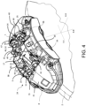
figure 4 shows an axonometric view of a brake caliper assembly comprising a brake caliper having a caliper tie-rod screwed to the caliper body, in which there is a spring assembly, according to the embodiment infigure 1 , and pad according to the present invention, in particular, a spring interacting with two opposite brake pads; -
figure 5 shows a view from the top of the brake caliper infigure 4 ; -
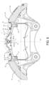
figure 6 shows a cross-section view of the brake caliper infigure 4 , in which the interaction of the spring with the caliper body and caliper tie-rod is shown, in which the spring in a rest condition not abutting against the caliper tie-rod is shown with a dotted line; -
figure 7 shows an axonometric view of a brake caliper assembly comprising a brake caliper having a caliper pin planted into the caliper body, in which there is a spring assembly, according to the embodiment infigure 1 , and pad according to the present invention, in particular, a spring which interacts with two opposite brake pads; -
figure 8 shows a view from the top of the brake caliper infigure 7 ; -
figure 9 shows a cross-section view of the brake caliper infigure 5 , in which the interaction of the spring with the caliper body and the caliper pin rod is shown, in which the spring in a rest condition not abutting against the caliper pin is shown with a dotted line; -
figure 10 shows in cross-section following a plane parallel to the rotation axis of the brake disc A-A and the radial direction R-R, a brake pad associated with a spring according to the invention at the beginning of an application of an external force Fext to the spring-brake pad assembly, in which a sliding force Fslip arises, which starts to alter the radial forces Frad and the axial forces Fax exchanged between spring and brake pad support plate, which generate the friction force Fatt, which maintains the balance between spring and pad; -
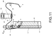
figure 11 shows a cross-section view of the brake pad in the same assembly asfigure 10 , in which the external force Fext has overcome the friction force Fatt and displaces the balance between the spring and the brake pad, balance which, however, is not altered by virtue of the abutment portion, i.e. a tongue, of the spring, which abuts against a backing portion of the supporting plate, which generates a constraint reaction R, which balances and cancels the effect of the external force Fext, allowing the optimal position between band spring and pad to be maintained. - . According to a general embodiment, a
spring 1 for acaliper body 8 is shaped to be arranged straddling abrake disc 2 to apply an elastic action on at least onebrake pad 3 to bias it away from saidbrake disc 2. - . Said
brake disc 2 is adapted to rotate about a rotation axis X-X, which defines an axial direction A-A, parallel to said rotation axis X-X, a radial direction R-R, orthogonal to said rotation axis X-X, and a tangential direction T-T orthogonal both to said axial direction A-A and to said radial direction R-R. - . Said at least one
brake pad 3 comprises asupport plate 31, which supportsfriction material 32, saidsupport plate 31 comprising a plate edge 33, which forms at least one firstplate thrust portion 34 and at least one second plate thrustportion 36. - . Said
band spring 1 comprises a band-shapedspring body 4. - .
Said caliper body 8 comprises a first elongated element or wheel side elongatedelement 38, a second elongated element or opposite wheel side elongatedelement 39, afirst side bridge 40 and asecond side bridge 41 adapted to connect said first elongatedelement 38 to said secondelongated element 39 straddling saidbrake disc 2 and leaving a central portion of saidcaliper body 8 free from a central connection bridge. - . Said
spring 1 comprises aspring body 4. - . Said
spring 1 comprises afirst thrust portion 5 adapted to apply said elastic action on said firstplate thrust portion 34 of said at least onebrake pad 3, biasing saidbrake pad 3 at least away from saidbrake disc 2 in axial direction A-A and radial direction R-R. - . Said
spring 1 comprises asecond thrust portion 6 adapted to apply said elastic action on said second plate thrustportion 36 of said at least onebrake pad 3, biasing saidbrake pad 3 at least away from saidbrake disc 2 in axial direction A-A and radial direction R-R. Said first thrustportion 5 and said second thrustportion 6 being diametrically opposed to apply said spring action in a balanced manner on said at least one brake pad. - . Said
spring 1 comprises afirst coupling portion 14 adapted to couple said spring with saidfirst side bridge 40. - . Said
spring 1 comprises asecond coupling portion 15 adapted to couple saidspring 1 with saidsecond side bridge 41 on a tangentially opposite side with respect to saidfirst coupling portion 14. - . Said
spring 1 comprises abacking portion 7 adapted to abut against acaliper pin 16 planted in saidcaliper body 8 or a caliper tie-rod 17 screwed to saidcaliper body 8 avoiding coupling with saidcaliper pin 16 or said caliper tie-rod 17. - . Advantageously, said
spring 1 comprises at least one concave spring portion 46 having a concavity facing towards saidbrake disc 2 so that at least saidbacking portion 7 is elastically movable in the radial direction R-R toward saidbrake disc 2 between a rest configuration and at least one work configuration, elastically stressing saidfirst coupling portion 14 and saidsecond coupling portion 15 along said tangential direction T-T in opposite directions. - . Advantageously, in said work configuration, said
backing portion 7 abuts against either saidcaliper pin 16 or said clamp tie-rod 17, stressing saidfirst coupling portion 14 and saidsecond coupling portion 15 against saidfirst side bridge 40 and against saidsecond side bridge 41, respectively. - . According to an embodiment, said
spring 1 comprises afirst spring arm 43 adapted to connect saidbacking portion 7 to saidfirst coupling portion 14. According to an embodiment, saidfirst spring arm 43 is either filiform or band-like. - . According to an embodiment, said
spring 1 comprises asecond spring arm 44 adapted to connect saidbacking portion 7 to saidsecond coupling portion 15. According to an embodiment, said springsecond arm 44 is either filiform or band-like. - . According to an embodiment, said
first spring arm 43 and saidsecond spring arm 44 diverge from saidbacking portion 7 along first opposite directions, which are inclined relative to said tangential direction T-T and relative to said radial direction R-R forming said at least one concave spring portion 46. - . According to an embodiment, said
first spring arm 43 and saidsecond spring arm 44 are arranged inclined relative to said axial direction A-A and also relative to said radial direction R-R. - . According to an embodiment, said
spring 1 forms a first angle V1 between saidfirst spring arm 43 and said axial direction A-A and an opposite first angle -V1 between saidsecond spring arm 44 and said axial direction A-A. - . According to an embodiment, said
spring 1 forms a second angle V2 between saidfirst spring arm 43 and said radial direction R-R, and an opposite second angle -V2 between saidsecond spring arm 44 and said radial direction R-R. - . According to an embodiment, said
spring 1 is shaped so that, in said work configuration, saidbacking portion 7 is constantly elastically biased in a radial direction R-R abutting against saidcaliper pin 16 or said caliper tie-rod 17 and so that saidfirst coupling portion 14 and saidsecond coupling portion 15 are constantly elastically biased in a tangential direction T-T against saidcaliper body 8. - . According to an embodiment, the concavity of said at least one concave spring portion 46 decreases between said rest position and said work position.
- . According to an embodiment, said
spring 1 comprises athird spring arm 47 adapted to connect saidfirst spring arm 43 to saidfirst coupling portion 14. According to an embodiment, saidthird spring arm 47 is either filiform or band-like. - . According to an embodiment, said
spring 1 comprises afourth spring arm 48 adapted to connect saidsecond spring arm 44 to saidsecond coupling portion 15. According to an embodiment, saidfourth spring arm 48 is either filiform or band-like. - . According to an embodiment, said
third spring arm 47 and saidfourth spring arm 48 extend along second opposite directions, which are inclined relative to said tangential direction T-T and to said radial direction R-R. - . According to an embodiment, at least said
first spring arm 43 and saidthird spring arm 47 form a secondconvex spring portion 50 having concavity opposite to said at least one concave spring portion 46. - . According to an embodiment, at least said
second spring arm 44 and saidfourth arm 48 form a thirdconvex spring portion 51 having concavity opposite to said at least one concave spring portion 46. - . According to an embodiment, the concavity of said second
convex spring portion 50 and the concavity of said thirdconvex spring portion 51 decrease between said rest position and said working position, biasing saidfirst coupling portion 14 and said second coupling portion against saidcaliper body 8 from diametrically opposite sides. - . According to an embodiment, said
backing portion 7 is folded in a U or a V forming a first springconvex spring portion 49 having concavity opposite to said at least one concave spring portion 46 adapted to abut against saidcaliper pin 16 or said caliper tie-rod 17. - . According to a first embodiment, said first
convex spring portion 49 divides said at least one concave spring portion 46 into a first concave spring portion 52 and a second concave spring portion 53. - . According to an embodiment, said
spring 1 comprises a first foldedportion 54 and a second foldedportion 55, which are directly connected to saidbacking portion 7 on opposite sides along said tangential direction T-T forming at least one portion of said at least one concave spring portion 46. - . According to an embodiment, said
backing portion 7 comprises a radiallyexternal backing surface 45 facing in a radial direction R-R in a direction opposite to saidbrake disc 2, said radiallyexternal backing surface 45 being adapted to abut against saidcaliper pin 16 or said caliper tie-rod 17. - . According to an embodiment, the concavity of said
backing portion 7 folded in a U or a V, between said rest configuration and said work configuration, increases to tighten saidbacking portion 7 against saidcaliper pin 16 or said caliper tie-rod 17. - . According to an embodiment, said
first coupling portion 14 is shaped to couple by snapping onto saidcaliper body 8. - . According to an embodiment, said
second coupling portion 15 is shaped to couple by snapping onto saidcaliper body 8. - . According to an embodiment, said
first coupling portion 14 is shaped to couple with saidcaliper body 8 forming a bilateral constraint of saidspring 1 to saidcaliper body 8. - . According to an embodiment, said
second coupling portion 15 is shaped to couple with saidcaliper body 8 forming a bilateral constraint of saidspring 1 to saidcaliper body 8. - . According to an embodiment, said
spring 1 comprises afifth spring arm 60 adapted to connect said first thrustportion 5 to saidfirst coupling portion 14. According to an embodiment, said at least onefifth spring arm 60 is either filiform or band-like. - . According to an embodiment, said
spring 1 comprises least onesixth spring arm 61 adapted to connect said second thrustportion 6 to saidsecond coupling portion 14. According to an embodiment, said at least onesixth spring arm 61 is either filiform or band-like. - . According to an embodiment, said
spring 1 is constrained to saidcaliper body 8 with saidfirst coupling portion 14 and saidsecond coupling portion 15, and saidspring 1 is constrained to saidcaliper pin 16 or to said caliper tie-rod 17 with saidbacking portion 7 exclusively forming three constraint zones. - . According to an embodiment, said
spring 1 comprises a plane of symmetry A-R, wherein said plane of symmetry A-R is perpendicular to said tangential direction T-T and symmetrically divides saidspring 1 in half. - . According to an embodiment, said first thrust
portion 14 and saidsecond thrust portion 15 are symmetrical to saidbacking portion 7. - . According to an embodiment, said
spring 1 comprises afirst connection portion 20 from which saidfirst spring arm 43 and saidthird spring arm 47 distance themselves, in which at least onefifth spring arm 60 is connected to saidfirst connection portion 20 supporting said first thrustportion 5 so as to be placed orthogonal to saidfirst spring arm 43 and to saidthird spring arm 47. - . According to an embodiment, said
spring 1 comprises asecond connection portion 21 from which saidsecond spring arm 44 and saidfourth spring arm 48 distance themselves, wherein at least onesixth spring arm 61 is connected to saidsecond connection portion 21 supporting said second thrustportion 6 to be placed orthogonal to saidsecond spring arm 44 and to saidfourth spring arm 48. - . According to an embodiment, said at least one
fifth spring arm 60 and said at least onesixth spring arm 61 are folded U or a V. - . According to an embodiment, said
spring 1 comprises a furtherfirst thrust portion 5 adapted to bias afurther brake pad 3 away from saidbrake disc 2, wherein said at least onefifth spring arm 60 connects said furtherfirst thrust portion 5 to saidfirst coupling portion 14. - . According to an embodiment, said
spring 1 further comprises asecond thrust portion 6 adapted to bias saidfurther brake pad 3 away from saidbrake disc 2, wherein said at least onesixth spring arm 61 connects said furthersecond thrust portion 6 to saidsecond coupling portion 15. - . According to an embodiment, said at least one
fifth spring arm 60 is shaped with two branches bent in a U or V shape, and in which said at least onesixth spring arm 61 is shaped with two branches bent in a U or V shape. - . According to an embodiment, said first thrust
portion 5 and said second thrustportion 6, when in operating conditions resting on said at least onepad 3, is arranged inclined relative to said axial direction A-A and also relative to said radial direction R-R, forming a predetermined angle A1 between said first thrustportion 5 or said second thrustportion 6, and said axial direction A-A and forming a predetermined angle A2 between said first thrustportion 5, or said second thrustportion 6, and said radial direction R-R. - . According to an embodiment, said
spring body 4 comprises at least one filiform spring body portion. - . According to an embodiment, said
spring body 4 is filiform. - . According to an embodiment, said
spring body 4 comprises at least one band-shaped portion. - . According to an embodiment, said
spring body 4 is completely band-shaped and is obtained from a shaped and bent blanked sheet of predetermined spring thickness 9, which forms a spring edge 10. - . According to an embodiment, said
spring body 4 is band-shaped and obtained from a blanked and shaped sheet of spring steel. - . According to an embodiment, said
spring 1 is a band spring, in which said plate edge 33 forms at least said firstplate thrust portion 34 and at least one different firstplate backing portion 35. Saidspring 1 comprises at least onefirst abutment portion 22. Saidfirst abutment portion 22 is adapted to abut against said firstplate backing portion 35 of said at least onebrake pad 3 forming a support on an area of said firstplate backing portion 35 which prevents any sliding of saidfirst thrust portion 5 when thespring 1 is subject to external actions. In particular, saidband spring 1 is prevented from permanently coupling with said at least onepad 3, avoiding a bilateral constraint in said first thrustportion 5 and saidfirst abutment portion 22 between saidspring 1 and said at least onepad 3. - . According to an embodiment, said
spring 1 is a band spring, wherein said plate edge 33 forms at least said second plate thrustportion 36 and at least one different secondplate backing portion 37. Saidspring 1 comprises at least onesecond abutment portion 23. Saidsecond abutment portion 23 is adapted to abut against said secondplate backing portion 37 of said at least onebrake pad 3 forming a support on an area of said secondplate backing portion 37 which prevents any sliding of saidsecond thrust portion 6 when thespring 1 is subject to external actions. In particular, saidband spring 1 is prevented from permanently coupling with said at least onepad 3, avoiding a bilateral constraint in said second thrustportion 6 and saidsecond abutment portion 23 between saidspring 1 and said at least onepad 3. - . According to an embodiment, said
spring body 4 comprises at least saidfirst coupling portion 14, saidbacking portion 7 and saidsecond coupling portion 15. - . According to an embodiment, said
spring body 4 comprises a secondspring body band 19 comprising at least said onefirst thrust portion 5. - . According to an embodiment, said
spring body 4 comprises a thirdspring body band 42 comprising at least saidsecond thrust portion 6. - . According to an embodiment, said second
spring body band 19 and said thirdspring body band 42 are connected to said firstspring body band 18, to arrange said first thrustportion 5 and said second thrustportion 6 orthogonal with respect to saidfirst coupling portion 14, saidbacking portion 7 and saidsecond coupling portion 15. - . According to an embodiment, said
spring body 4 comprises a firstspring body band 18 comprising at least saidfirst coupling portion 14, saidbacking portion 7 and saidsecond coupling portion 15. Said firstspring body band 18 is band-shaped. - . According to an embodiment, said
spring body 4 comprises a first spring body thread 180 comprising at least saidfirst coupling portion 14, saidbacking portion 7, and saidsecond coupling portion 15. Said first spring body thread 180 is filiform. - . According to an embodiment, said
spring body 4 comprises a secondspring body thread 190 each comprising at least onefirst thrust portion 5. Said secondspring body thread 190 is filiform. - . According to an embodiment, said
spring body 4 comprises a thirdspring body thread 420 each comprising at least saidsecond thrust portion 6. Said thirdspring body thread 420 is filiform. - . According to an embodiment, said second
spring body thread 190 and said thirdspring body thread 420 are connected to said firstspring body band 18, so as to arrange said first thrustportion 5 and said second thrustportion 6 orthogonal with respect to saidfirst coupling portion 14, to saidbacking portion 7 and to saidsecond coupling portion 15. - . According to an embodiment, said second
spring body thread 190 and said thirdspring body thread 420 are connected to said first spring body band 180, so as to arrange said first thrustportion 5 and said second thrustportion 6 orthogonal with respect to saidfirst coupling portion 14, to saidbacking portion 7 and to saidsecond coupling portion 15. - . According to an embodiment, said
first abutment portion 22 extends cantilevered from saidspring body 4. - . According to an embodiment, said
second abutment portion 23 extends cantilevered from saidspring body 4. - . According to an embodiment, said
first abutment portion 22 comprises opposite first abutment portion flat faces 11, 12 and a first abutment portion edge 13, and saidfirst abutment portion 22 rests abutting against said firstplate backing portion 35 with one of said opposite first abutment portion flat faces 11 or 12. - . According to an embodiment, said
first abutment portion 22 comprises opposite first abutment portion flat faces 11, 12 and a first portion abutment edge 13, and saidfirst abutment portion 22 rests abutting against said firstbacking portion plate 35 with said first abutment portion edge 13. - . According to an embodiment, said
second abutment portion 23 comprises opposite second abutment portion flat faces 27, 28 and a second abutment portion edge 29, and saidsecond abutment portion 23 rests abutting against said secondplate backing portion 37 with one of said opposite second abutment portion flat faces 27 or 28. - . According to an embodiment, said
second abutment portion 23 comprises opposite second abutment portion flat faces 27, 28 and a second abutment portion edge 29, and saidsecond abutment portion 23 rests abutting against said secondplate backing portion 37 with said second abutment portion edge 29. - . According to an embodiment, said
first abutment portion 22, when it rests abutting against saidplate backing portion 35 is stressed to bend. - . According to an embodiment, said
second abutment portion 23, when it rests abutting against saidplate backing portion 37 is stressed to bend. - . According to an embodiment, said
first abutment portion 22 extends cantilevered from at least onefifth spring arm 60. - . According to an embodiment, said
third abutment portion 23 extends cantilevered from at least onesixth spring arm 61. - . The present invention further relates to a spring assembly and brake pad comprising at least one
spring 1 according to any one of the embodiments described above and at least onebrake pad 3. - . The present invention further relates to a brake caliper assembly comprising at least one
spring 1 according to any one of the embodiments described above and at least onebrake pad 3. - . Said brake caliper assembly comprises a
brake caliper 24 comprising acaliper body 8 adapted to be arranged straddling abrake disc 2, saidbrake disc 2 being adapted to rotate about a rotation axis X-X, which defines an axial direction A-A, parallel to said rotation axis X-X, a radial direction R-R, orthogonal to said rotation axis X-X, and a tangential direction T-T orthogonal both to said axial direction A-A and to said radial direction R-R. - .
Said caliper body 8 comprises a first elongated element or wheel side elongatedelement 38, a second elongated element or opposite wheel side elongatedelement 39, afirst side bridge 40, and asecond side bridge 41 adapted to connect said first elongatedelement 38 to said secondelongated element 39 to straddle saidbrake disc 2, leaving a central portion of saidcaliper body 8 free from a central connection bridge, and wherein said caliper body comprises seats adapted to support thrust elements orpistons 26 configured to stress said at least one pad towards saidbrake disc 2. - . Said caliper assembly comprises at least one pad sliding and
support pin 25 connected to said caliper body and supporting said at least onebrake pad 3. - . Said caliper assembly comprises a supporting
assembly caliper pin 16 planted in saidcaliper body 8 in said central portion ofcaliper body 8 between said firstelongated element 39 and said secondelongated element 39, or said caliper assembly comprises a caliper tie-rod 17 screwed into saidcaliper body 8 in said central portion ofcaliper body 8 between said firstelongated element 39 and said secondelongated element 39. - . Said
spring 1 has saidbacking portion 7 abutting against saidcaliper pin 16 or said caliper tie-rod 17 and stressed in a radial direction (R-R). - . Said
spring 1 has saidfirst coupling portion 14 and saidsecond coupling portion 15 coupled with saidfirst side bridge 40 and saidsecond side bridge 41 and a tangential direction T-T against saidfirst side bridge 40 and against saidsecond side bridge 41 respectively, avoiding interactions of saidspring 1 with each pad support and slidingpin 25. - . According to an embodiment, said caliper assembly avoids interactions of said
spring 1 with each pad supporting and slidingpin 25. -
- 1
- band spring
- 2
- brake disc
- 3
- brake pad
- 3'
- further brake pad
- 4
- spring body
- 5
- first thrust portion
- 6
- second thrust portion
- 7
- backing portion
- 8
- caliper body
- 9
- spring thickness
- 10
- spring edge
- 11
- first abutment portion flat face
- 12
- first abutment portion flat face
- 13
- first abutment portion edge
- 14
- first coupling portion
- 15
- second coupling portion
- 16
- caliper pin
- 17
- caliper tie-rod
- 18
- spring body first band
- 19
- spring body second band
- 20
- first connection portion
- 21
- second connection portion
- 22
- first abutment portion
- 23
- second abutment portion
- 24
- brake caliper
- 25
- pad supporting and sliding pins
- 26
- thrust elements or pistons
- 27
- second abutment portion flat face
- 28
- second abutment portion flat face
- 29
- second abutment portion edge
- 30
- boss-shaped protuberance
- 31
- backing plate
- 32
- friction material
- 33
- plate edge
- 34
- first plate thrust portion
- 35
- first plate backing portion
- 36
- second plate thrust portion
- 37
- second plate backing portion
- 38
- first elongated element or wheel side elongated element
- 39
- second elongated element or opposite wheel-side elongated element
- 40
- first side bridge
- 41
- second side bridge
- 42
- third spring body band
- 43
- first spring arm
- 44
- second spring arm
- 45
- radially external backing surface
- 46
- at least one concave spring portion
- 47
- third spring arm
- 48
- fourth spring arm
- 49
- first convex spring portion
- 50
- second convex spring portion
- 51
- third convex spring portion
- 52
- first concave spring portion
- 53
- second concave spring portion
- 54
- first bent spring portion
- 55
- second bent spring portion
- 56
- third bent spring portion
- 57
- fourth bent spring portion
- 58
- fifth bent spring portion
- 59
- sixth bent spring portion
- 60
- fifth spring arm
- 61
- sixth spring arm
- 180
- first spring body thread
- 190
- second spring body thread
- 420
- third spring body thread
- X-X
- rotation axis or revolution axis of an axial-symmetrical surface
- A-A
- axial direction
- R-R
- radial direction
- T-T
- tangential direction
- C-C
- circumferential direction
- A1
- angle between first or second thrust portion and axial direction
- A2
- angle between first or second thrust portion and radial direction
- V1
- angle between first or second spring arm in axial direction
- V2
- angle between first or second spring arm in radial direction
Claims (11)
- A spring (1) for a caliper body (8) wherein said spring (1) is shaped to be arranged straddling a brake disc (2) for applying an elastic action on at least one brake pad (3) to bias it away from said brake disc (2); wherein- said brake disc (2) is adapted to rotate about a rotation axis (X-X), which defines an axial direction (A-A), parallel to said rotation axis (X-X), a radial direction (R-R), orthogonal to said rotation axis (X-X), and a tangential direction (T-T) orthogonal both to said axial direction (A-A) and to said radial direction (R-R) ;- said at least one brake pad (3) comprises a support plate (31), which supports friction material (32), said support plate (31) comprising a plate edge (33) forming at least one first plate thrust portion (34) and at least one second plate thrust portion (36);- said caliper body (8) comprising a first elongated element or wheel side elongated element (38), a second elongated element or opposite wheel side elongated element (39), a first side bridge (40) and a second side bridge (41) adapted to connect said first elongated element (38) to said second elongated element (39) straddling said brake disc (2) and leaving a central portion of said caliper body (8) free from a central connection bridge,- said spring (1) comprises a spring body (4);said spring (1) comprising:- a first thrust portion (5) adapted to apply said elastic action on said first plate thrust portion (34) of said at least one brake pad (3), biasing said brake pad (3) at least away from said brake disc (2) in an axial direction (A-A) and in a radial direction (R-R);- a second thrust portion (6) adapted to apply said elastic action on said second plate thrust portion (36) of said at least one brake pad (3), biasing said brake pad (3) at least away from said brake disc (2) in an axial direction (A-A) and in a radial direction (R-R) ;- a first coupling portion (14) adapted to couple said spring with said first side bridge (40);- a second coupling portion (15) adapted to couple said spring (1) with said second side bridge (41) on a tangentially opposite side with respect to said first coupling portion (14),- a backing portion (7) adapted to abut against a caliper pin (16) planted in said caliper body (8) or a caliper tie-rod (17) screwed to said caliper body (8) avoiding coupling with said caliper pin (16) or said caliper tie-rod (17),wherein said spring (1) comprises at least one concave spring portion (46) having a concavity facing towards said brake disc (2) so that at least said backing portion (7) is elastically movable in a radial direction (R-R) towards said brake disc (2) between a rest configuration and at least a work configuration, elastically stressing said first coupling portion (14) and said second coupling portion (15) along said tangential direction (T-T) in opposite directions, in which, in said work configuration, said backing portion (7) abuts against said caliper pin (16) or said caliper tie-rod (17), stressing said first coupling portion (14) and said coupling portion (15) against said first side bridge (40) and against said second side bridge (41), respectively.
- A spring (1) according to the preceding claim comprising- a first spring arm (43) adapted to connect said backing portion (7) to said first coupling portion (14),- a second spring arm (44) adapted to connect said backing portion (7) to said second coupling portion (15),wherein said first spring arm (43) and said second spring arm (44) diverge from said backing portion (7) along first opposite directions, which are inclined with respect to said tangential direction (T-T) and with respect to said radial direction (R-R) forming said at least one concave spring portion (46),and/or wherein said spring (1) is shaped so that, in said work configuration, said backing portion (7) is constantly elastically biased in a radial direction (R-R) abutting against said caliper pin (16) or said caliper tie-rod (17) and so that said first coupling portion (14) and said second coupling portion (15) are constantly elastically biased in a tangential direction (T-T) against said caliper body (8),and/or wherein the concavity of said at least one concave spring portion (46) decreases between said rest position and said work position.
- A spring (1) according to the preceding claim comprising- a third spring arm (47) adapted to connect said first spring arm (43) to said first coupling portion (14),- a fourth spring arm (48) adapted to connect said second spring arm (44) to said second coupling portion (15),wherein said third spring arm (47) and said fourth spring arm (48) extend along second opposite directions that are inclined with respect to said tangential direction (T-T) and to said radial direction (R-R),wherein at least said first spring arm (43) and said third spring arm (47) form a second convex spring portion (50) having concavity that is opposite to said at least one concave spring portion (46), and wherein at least said second spring arm (44) and said fourth arm (48) form a third convex spring portion (51) having concavity that is opposite to said at least one concave spring portion (46),and/or wherein the concavity of said second convex spring portion (50) and the concavity of said third convex spring portion (51) decrease between said rest position and said work position.
- A spring (1) according to any one of the preceding claims, wherein said backing portion (7) is folded in a U or a V forming a first spring convex spring portion (49) having opposite concavity to said at least one concave spring portion (46) adapted to abut against said caliper pin (16) or said caliper tie-rod (17),wherein said first convex spring portion (49) divides said at least one concave spring portion (46) into a first concave spring portion (52) and a second concave spring portion (53),and/or wherein said spring (1) comprises a first folded portion (54) and a second folded portion (55), which are directly connected to said backing portion (7) on opposite sides along said tangential direction (T-T) forming at least one portion of said at least one concave spring portion (46),and/or wherein said backing portion (7) comprises a radially external backing surface (45) facing in a radial direction (R-R) in an opposite direction to said brake disc (2), said radially external backing surface (45) being adapted to abut against said caliper pin (16) or said caliper tie-rod (17),and/or wherein the concavity of said backing portion (7) folded in a U or a V, between said rest configuration and said work configuration, increases so as to tighten said backing portion (7) against said caliper pin (16) or said caliper tie-rod (17);and/or wherein said first coupling portion (14) is shaped so as to snap couple with said caliper body (8);and/or whereinsaid second coupling portion (15) is shaped so as to snap couple with said caliper body (8);and/or whereinsaid first coupling portion (14) is shaped so as to couple with said caliper body (8) forming a bilateral constraint of the spring (1) with the caliper body (8);and/or whereinsaid second coupling portion (15) is shaped so as to couple with said caliper body (8) forming a bilateral constraint of the spring (1) with the caliper body (8).
- A spring (1) according to any one of the preceding claims, comprising- at least a fifth spring arm (60) adapted to connect said first thrust portion (5) to said first coupling portion (14),- at least a sixth spring arm (61) adapted to connect said second thrust portion (6) to said second coupling portion (14),and/or wherein said spring (1) is constrained to said caliper body (8) with said first coupling portion (14) and said second coupling portion (15), and said spring (1) is constrained to said caliper pin (16) or to said caliper tie-rod (17) with said backing portion (7) exclusively forming three constraint areas;and/or wherein said spring (1) comprises a plane of symmetry (A-R), wherein said plane of symmetry (A-R) is perpendicular to said tangential direction (T-T) and symmetrically divides said spring (1) in half,and/or wherein said first thrust portion (14) and said second thrust portion (15) are symmetrical to said backing portion (7);and/or wherein said spring (1) comprises a first connection portion (20) from which said first spring arm (43) and said third spring arm (47) distance themselves, wherein at least one fifth spring arm (60) is connected to said first connection portion (20) supporting said first thrust portion (5) so as to be placed orthogonal to said first spring arm (43) and to said third spring arm (47),and/or wherein said spring (1) comprises a second connection portion (21) from which said second spring arm (44) and said fourth spring arm (48) distance themselves, wherein at least one sixth spring arm (61) is connected to said second connection portion (21) supporting said second thrust portion (6) so as to be placed orthogonal to said second spring arm (44) and to said fourth spring arm (48).
- A spring (1) according to the preceding claim, wherein said at least one fifth spring arm (60) and said at least one sixth spring arm (61) are folded in a U or a V,and/or wherein said at least one fifth spring arm (60) is shaped with two branches folded in a U or a V each respectively connected to at least one of said at least one first thrust portion (14), and wherein said at least one sixth spring arm (61) is shaped with two branches folded in a U or a V each respectively connected to at least one of said at least one second thrust portion (15);and/or wherein said first thrust portion (5) and said second thrust portion (6), when in operating conditions resting on said at least one pad (3), is arranged inclined with respect to said axial direction (A-A) and also with respect to said radial direction (R-R), forming a predetermined angle (A1) between said first thrust portion (5) or said second thrust portion (6), and said axial direction (A-A) and forming a predetermined angle (A2) between said first thrust portion (5), or said second thrust portion (6), and said radial direction (R-R).
- A spring (1) according to any one of the preceding claims, wherein said spring body (4) comprises at least one filiform spring body portion, or is filiform; orsaid spring body (4) comprises at least one band-shaped portion or is completely band-shaped and is obtained from a shaped and bent sheared sheet of predetermined spring thickness (9) which forms a spring edge (10); orsaid spring body (4) is band-shaped and is obtained from a sheared and shaped sheet of spring steel.
- A spring (1), according to the preceding claim, whereinsaid spring (1) is a band spring, wherein said plate edge (33) forms at least said first plate thrust portion (34) and a different at least one first plate backing portion (35);wherein said spring (1) comprises at least one first abutment portion (22),wherein said first abutment portion (22) is adapted to abut against said first plate backing portion (35) of said at least one brake pad (3) forming a support on an area of said first plate backing portion (35) which prevents any sliding of said first thrust portion (5) when the spring (1) is subject to external actions;- preventing said spring (1) from permanently coupling with said at least one pad (3), avoiding a bilateral constraint in said first thrust portion (5) and said first abutment portion (22) between said spring (1) and said at least one pad (3);and/or wherein said spring (1) is a band spring,wherein said plate edge (33) forms at least said second plate thrust portion (36) and a different at least one second plate backing portion (37);wherein said spring (1) comprises at least a second abutment portion (23),wherein said second abutment portion (23) is adapted to abut against said second plate backing portion (37) of said at least one brake pad (3) forming a support on an area of said second plate backing portion (37) which prevents any sliding of said second thrust portion (6) when the spring (1) is subject to external actions;- preventing said spring (1) from permanently coupling with said at least one pad (3), avoiding a bilateral constraint in said second thrust portion (6) and said second abutment portion (23) between said spring (1) and said at least one pad (3);and/or wherein said spring body (4) comprises- a first spring body band (18) comprising at least said first coupling portion (14), said backing portion (7) and said second coupling portion (15),- a second spring body band (19) comprising at least said first thrust portion (5), and- a third spring body band (42) comprising at least said second thrust portion (6),wherein said second spring body band (19) and said third spring body band (42) are connected to said first spring body band (18), so as to arrange said first thrust portion (5) and said second thrust portion (6) orthogonal to said first coupling portion (14), said backing portion (7) and said second coupling portion (15); or wherein said spring body (4) comprises- a first spring body band (18), or a first spring body thread (180), comprising at least said first coupling portion (14), said backing portion (7) and said second coupling portion (15), wherein said first spring body band (18) is band-shaped or said first spring body thread (180) is filiform;- a second spring body thread (190) comprising at least said first thrust portion (5), wherein said second spring body thread (190) is filiform, and- a third spring body thread (420) comprising at least said second thrust portion (6), wherein said third spring body thread (420) is filiform,wherein said second spring body thread (190) and said third spring body thread (420) are connected to said first spring body band (18), so as to arrange said first thrust portion (5) and said second thrust portion (6) orthogonal to said first coupling portion (14), said backing portion (7) and said second coupling portion (15).
- A spring (1) according to the preceding claim, whereinsaid first abutment portion (22) extends in a cantilever fashion from said spring body (4); and/or wherein said second abutment portion (23) extends in a cantilever fashion from said spring body (4) ;and/or whereinsaid first abutment portion (22) comprises first abutment portion opposite flat faces (11, 12) and a first abutment portion edge (13) andsaid first abutment portion (22) rests abutting against said first plate backing portion (35) with one of said first abutment portion opposite flat faces (11 or 12);
orsaid first abutment portion (22) comprises first abutment portion opposite flat faces (11, 12) and a first abutment portion edge (13) andsaid first abutment portion (22) rests abutting against said first plate backing portion (35) with said first abutment portion edge (13) ;and/or whereinsaid second abutment portion (23) comprises second abutment portion opposite flat faces (27, 28) and a second abutment portion edge (29) andsaid second abutment portion (23) rests abutting against said second plate backing portion (37) with one of said second abutment portion opposite flat faces (27 or 28);
orsaid second abutment portion (23) comprises second abutment portion opposite flat faces (27, 28) and a second abutment portion edge (29) andsaid second abutment portion (23) rests abutting against said second plate backing portion (37) with said second abutment portion edge (29) ;and/or whereinsaid first abutment portion (22), when it rests abutting against said first plate backing portion (35), is stressed to bend;and/or whereinsaid second abutment portion (23), when it rests abutting against said plate backing portion (37), is stressed to bend;and/or whereinsaid first abutment portion (22) extends in a cantilever fashion from at least a fifth spring arm (60);and/or whereinsaid second abutment portion (23) extends cantilever fashion from at least a sixth spring arm (61). - A spring assembly and brake pad comprising:at least one spring (1) according to any one of the preceding claims, andat least one brake pad (3) comprising a support plate (31), to which a friction material (32) is supported, said support plate (31) comprising a plate edge (33) which forms at least one first plate thrust portion (34) and at least one second plate thrust portion (36) .
- A brake caliper assembly, comprising:at least one spring assembly and pad according to the preceding claim, anda brake caliper (24) comprising a caliper body (8) adapted to be arranged straddling a brake disc (2), said brake disc (2) being adapted to rotate about a rotation axis (X-X), which defines an axial direction (A-A), parallel to said rotation axis (X-X), a radial direction (R-R), orthogonal to said rotation axis (X-X), anda tangential direction (T-T) orthogonal both to said axial direction (A-A) and to said radial direction (R-R);said caliper body (8) comprising a first elongated element or wheel side elongated element (38), a second elongated element or opposite wheel side elongated element (39), a first side bridge (40) and a second side bridge (41) adapted to connect said first elongated element (38) to said second elongated element (39) so as to straddle said brake disc (2), leaving a central portion of said caliper body (8) free from a central connection bridge, and wherein said caliper body comprises seats adapted to support thrust elements or pistons (26) configured to stress said at least one pad towards said brake disc (2),- at least one pad sliding and support pin (25) connected to said caliper body and supporting said at least one brake pad (3),said brake caliper assembly further comprising:- a caliper pin (16) planted in said caliper body (8) in said central portion of caliper body (8) between said first elongated element (39) and said second elongated element (39), or- a caliper tie-rod (17) screwed into said caliper body (8) in said central portion of caliper body (8) between said first elongated element (39) and said second elongated element (39),wherein said spring (1) has said backing portion (7) abutting against said caliper pin (16) or said caliper tie-rod (17) and stressed in a radial direction (R-R),and wherein said spring (1) has said first coupling portion (14) and said second coupling portion (15) coupled with said first side bridge (40) and said second side bridge (41) and stressed in a tangential direction (T-T) against said first side bridge (40) and against said second side bridge (41), respectively.
Applications Claiming Priority (1)
| Application Number | Priority Date | Filing Date | Title |
|---|---|---|---|
| IT102021000025361A IT202100025361A1 (en) | 2021-10-04 | 2021-10-04 | Spring, spring and brake pad assembly, caliper body assembly |
Publications (2)
| Publication Number | Publication Date |
|---|---|
| EP4160043A1 true EP4160043A1 (en) | 2023-04-05 |
| EP4160043B1 EP4160043B1 (en) | 2024-06-26 |
Family
ID=79018749
Family Applications (1)
| Application Number | Title | Priority Date | Filing Date |
|---|---|---|---|
| EP22198934.6A Active EP4160043B1 (en) | 2021-10-04 | 2022-09-30 | Spring, spring assembly and brake pad, caliper body assembly |
Country Status (4)
| Country | Link |
|---|---|
| US (1) | US12422007B2 (en) |
| EP (1) | EP4160043B1 (en) |
| CN (1) | CN115929818A (en) |
| IT (1) | IT202100025361A1 (en) |
Families Citing this family (8)
| Publication number | Priority date | Publication date | Assignee | Title |
|---|---|---|---|---|
| WO2020125954A1 (en) * | 2018-12-18 | 2020-06-25 | Volvo Truck Corporation | Wheel brake arrangement |
| IT201800020401A1 (en) * | 2018-12-20 | 2020-06-20 | Freni Brembo Spa | PAD RETURN SPRING FOR A DISC BRAKE CALIPER BODY |
| KR102792005B1 (en) * | 2020-02-19 | 2025-04-08 | 현대모비스 주식회사 | Brake apparatus for vehicle |
| EP3954919B1 (en) * | 2020-08-11 | 2024-10-02 | Meritor Heavy Vehicle Braking Systems (UK) Limited | Brake assembly |
| USD1044636S1 (en) * | 2021-12-24 | 2024-10-01 | A.P. Racing Ltd | Brake caliper |
| KR20240152014A (en) * | 2023-04-12 | 2024-10-21 | 에이치엘만도 주식회사 | Disk brake caliper and disk brake appratus |
| CN120140378A (en) * | 2023-12-13 | 2025-06-13 | 布雷博(南京)汽车零部件有限公司 | Disc brakes |
| CN120171475B (en) * | 2025-05-23 | 2025-09-09 | 北京金万安汽车电子技术研发有限公司 | A band spring brake and its braking system |
Citations (7)
| Publication number | Priority date | Publication date | Assignee | Title |
|---|---|---|---|---|
| US20040262099A1 (en) * | 2001-10-31 | 2004-12-30 | Cristian Crippa | Flat spring for preloading disc brake pads |
| JP2008032125A (en) * | 2006-07-28 | 2008-02-14 | Hitachi Ltd | Disc brake |
| DE102017204696A1 (en) | 2017-03-21 | 2018-09-27 | Continental Teves Ag & Co. Ohg | One-piece return spring for vehicle disc brake pads |
| WO2019243958A1 (en) | 2018-06-20 | 2019-12-26 | Freni Brembo S.P.A. | Spring for friction pads in a disc brake caliper |
| WO2020128946A1 (en) | 2018-12-20 | 2020-06-25 | Freni Brembo S.P.A. | Pad return spring for a disc brake caliper body |
| WO2020128710A1 (en) | 2018-12-20 | 2020-06-25 | Freni Brembo S.P.A. | Pad-and-spring assembly for a brake caliper |
| WO2021161642A1 (en) * | 2020-02-12 | 2021-08-19 | 日立Astemo株式会社 | Vehicle disc brake |
Family Cites Families (1)
| Publication number | Priority date | Publication date | Assignee | Title |
|---|---|---|---|---|
| IT201600130800A1 (en) * | 2016-12-23 | 2018-06-23 | Freni Brembo Spa | Spring device for disc brake, pad and spring assembly and brake caliper |
-
2021
- 2021-10-04 IT IT102021000025361A patent/IT202100025361A1/en unknown
-
2022
- 2022-09-30 EP EP22198934.6A patent/EP4160043B1/en active Active
- 2022-10-03 US US17/937,536 patent/US12422007B2/en active Active
- 2022-10-09 CN CN202211227029.4A patent/CN115929818A/en active Pending
Patent Citations (8)
| Publication number | Priority date | Publication date | Assignee | Title |
|---|---|---|---|---|
| US20040262099A1 (en) * | 2001-10-31 | 2004-12-30 | Cristian Crippa | Flat spring for preloading disc brake pads |
| JP2008032125A (en) * | 2006-07-28 | 2008-02-14 | Hitachi Ltd | Disc brake |
| DE102017204696A1 (en) | 2017-03-21 | 2018-09-27 | Continental Teves Ag & Co. Ohg | One-piece return spring for vehicle disc brake pads |
| WO2019243958A1 (en) | 2018-06-20 | 2019-12-26 | Freni Brembo S.P.A. | Spring for friction pads in a disc brake caliper |
| US20210270335A1 (en) * | 2018-06-20 | 2021-09-02 | Freni Brembo S.P.A. | Spring for friction pads in a disc brake caliper |
| WO2020128946A1 (en) | 2018-12-20 | 2020-06-25 | Freni Brembo S.P.A. | Pad return spring for a disc brake caliper body |
| WO2020128710A1 (en) | 2018-12-20 | 2020-06-25 | Freni Brembo S.P.A. | Pad-and-spring assembly for a brake caliper |
| WO2021161642A1 (en) * | 2020-02-12 | 2021-08-19 | 日立Astemo株式会社 | Vehicle disc brake |
Also Published As
| Publication number | Publication date |
|---|---|
| EP4160043B1 (en) | 2024-06-26 |
| US12422007B2 (en) | 2025-09-23 |
| IT202100025361A1 (en) | 2023-04-04 |
| CN115929818A (en) | 2023-04-07 |
| US20230109487A1 (en) | 2023-04-06 |
Similar Documents
| Publication | Publication Date | Title |
|---|---|---|
| EP4160043B1 (en) | Spring, spring assembly and brake pad, caliper body assembly | |
| CN108350963B (en) | Disk brake for a commercial vehicle and brake lining set | |
| CN107850145B (en) | Disc brakes and brake lining sets for commercial vehicles | |
| CN106715945B (en) | Disc brakes | |
| JP2003517143A (en) | Guide springs for friction elements and disc brakes fitted with at least one such spring | |
| CN100580268C (en) | disc brake unit | |
| US6957724B2 (en) | Vehicle disk brake | |
| EP3810950A1 (en) | Spring for friction pads in a disc brake caliper | |
| US20240077121A1 (en) | Band spring and band spring and brake pad assembly | |
| US11852207B2 (en) | Assembly of at least two brake pads and at least one spring | |
| EP4107405B1 (en) | Brake pad retainer system, brake pad and vehicle | |
| US20240110603A1 (en) | Band spring for returning brake pads on a caliper | |
| TW480319B (en) | Brake assembly | |
| JPH0262433A (en) | Spot type disk brake | |
| US5388670A (en) | Wear-limit warning anti-rattle spring | |
| EP0094736B1 (en) | Disc brakes | |
| JPH06109041A (en) | Disc brakes for vehicles | |
| WO2025094039A1 (en) | Band spring shaped to be arranged straddling a brake disc | |
| CN119373813A (en) | Caliper body and brake pad assembly | |
| GB2090928A (en) | Improvements relating to friction pad assemblies for use in disc brakes | |
| US20040238293A1 (en) | Retaining structure for pad holding pins of disc brakes | |
| US20250215943A1 (en) | Brake caliper of the floating type of a disc brake | |
| JP4918419B2 (en) | Drum brake with shoe clearance automatic adjustment mechanism | |
| WO2024003804A1 (en) | Band spring and brake pad assembly, brake caliper, brake pad | |
| JPS6148013B2 (en) |
Legal Events
| Date | Code | Title | Description |
|---|---|---|---|
| PUAI | Public reference made under article 153(3) epc to a published international application that has entered the european phase |
Free format text: ORIGINAL CODE: 0009012 |
|
| STAA | Information on the status of an ep patent application or granted ep patent |
Free format text: STATUS: THE APPLICATION HAS BEEN PUBLISHED |
|
| AK | Designated contracting states |
Kind code of ref document: A1 Designated state(s): AL AT BE BG CH CY CZ DE DK EE ES FI FR GB GR HR HU IE IS IT LI LT LU LV MC MK MT NL NO PL PT RO RS SE SI SK SM TR |
|
| P01 | Opt-out of the competence of the unified patent court (upc) registered |
Effective date: 20230526 |
|
| STAA | Information on the status of an ep patent application or granted ep patent |
Free format text: STATUS: REQUEST FOR EXAMINATION WAS MADE |
|
| 17P | Request for examination filed |
Effective date: 20230821 |
|
| RBV | Designated contracting states (corrected) |
Designated state(s): AL AT BE BG CH CY CZ DE DK EE ES FI FR GB GR HR HU IE IS IT LI LT LU LV MC MK MT NL NO PL PT RO RS SE SI SK SM TR |
|
| GRAP | Despatch of communication of intention to grant a patent |
Free format text: ORIGINAL CODE: EPIDOSNIGR1 |
|
| STAA | Information on the status of an ep patent application or granted ep patent |
Free format text: STATUS: GRANT OF PATENT IS INTENDED |
|
| INTG | Intention to grant announced |
Effective date: 20240221 |
|
| GRAS | Grant fee paid |
Free format text: ORIGINAL CODE: EPIDOSNIGR3 |
|
| GRAA | (expected) grant |
Free format text: ORIGINAL CODE: 0009210 |
|
| STAA | Information on the status of an ep patent application or granted ep patent |
Free format text: STATUS: THE PATENT HAS BEEN GRANTED |
|
| AK | Designated contracting states |
Kind code of ref document: B1 Designated state(s): AL AT BE BG CH CY CZ DE DK EE ES FI FR GB GR HR HU IE IS IT LI LT LU LV MC MK MT NL NO PL PT RO RS SE SI SK SM TR |
|
| REG | Reference to a national code |
Ref country code: GB Ref legal event code: FG4D |
|
| REG | Reference to a national code |
Ref country code: CH Ref legal event code: EP |
|
| REG | Reference to a national code |
Ref country code: DE Ref legal event code: R096 Ref document number: 602022004145 Country of ref document: DE |
|
| PG25 | Lapsed in a contracting state [announced via postgrant information from national office to epo] |
Ref country code: BG Free format text: LAPSE BECAUSE OF FAILURE TO SUBMIT A TRANSLATION OF THE DESCRIPTION OR TO PAY THE FEE WITHIN THE PRESCRIBED TIME-LIMIT Effective date: 20240626 |
|
| PG25 | Lapsed in a contracting state [announced via postgrant information from national office to epo] |
Ref country code: FI Free format text: LAPSE BECAUSE OF FAILURE TO SUBMIT A TRANSLATION OF THE DESCRIPTION OR TO PAY THE FEE WITHIN THE PRESCRIBED TIME-LIMIT Effective date: 20240626 Ref country code: HR Free format text: LAPSE BECAUSE OF FAILURE TO SUBMIT A TRANSLATION OF THE DESCRIPTION OR TO PAY THE FEE WITHIN THE PRESCRIBED TIME-LIMIT Effective date: 20240626 |
|
| REG | Reference to a national code |
Ref country code: LT Ref legal event code: MG9D |
|
| PG25 | Lapsed in a contracting state [announced via postgrant information from national office to epo] |
Ref country code: GR Free format text: LAPSE BECAUSE OF FAILURE TO SUBMIT A TRANSLATION OF THE DESCRIPTION OR TO PAY THE FEE WITHIN THE PRESCRIBED TIME-LIMIT Effective date: 20240927 |
|
| PG25 | Lapsed in a contracting state [announced via postgrant information from national office to epo] |
Ref country code: LV Free format text: LAPSE BECAUSE OF FAILURE TO SUBMIT A TRANSLATION OF THE DESCRIPTION OR TO PAY THE FEE WITHIN THE PRESCRIBED TIME-LIMIT Effective date: 20240626 |
|
| REG | Reference to a national code |
Ref country code: NL Ref legal event code: MP Effective date: 20240626 |
|
| PG25 | Lapsed in a contracting state [announced via postgrant information from national office to epo] |
Ref country code: NO Free format text: LAPSE BECAUSE OF FAILURE TO SUBMIT A TRANSLATION OF THE DESCRIPTION OR TO PAY THE FEE WITHIN THE PRESCRIBED TIME-LIMIT Effective date: 20240926 Ref country code: LV Free format text: LAPSE BECAUSE OF FAILURE TO SUBMIT A TRANSLATION OF THE DESCRIPTION OR TO PAY THE FEE WITHIN THE PRESCRIBED TIME-LIMIT Effective date: 20240626 Ref country code: HR Free format text: LAPSE BECAUSE OF FAILURE TO SUBMIT A TRANSLATION OF THE DESCRIPTION OR TO PAY THE FEE WITHIN THE PRESCRIBED TIME-LIMIT Effective date: 20240626 Ref country code: GR Free format text: LAPSE BECAUSE OF FAILURE TO SUBMIT A TRANSLATION OF THE DESCRIPTION OR TO PAY THE FEE WITHIN THE PRESCRIBED TIME-LIMIT Effective date: 20240927 Ref country code: FI Free format text: LAPSE BECAUSE OF FAILURE TO SUBMIT A TRANSLATION OF THE DESCRIPTION OR TO PAY THE FEE WITHIN THE PRESCRIBED TIME-LIMIT Effective date: 20240626 Ref country code: BG Free format text: LAPSE BECAUSE OF FAILURE TO SUBMIT A TRANSLATION OF THE DESCRIPTION OR TO PAY THE FEE WITHIN THE PRESCRIBED TIME-LIMIT Effective date: 20240626 Ref country code: RS Free format text: LAPSE BECAUSE OF FAILURE TO SUBMIT A TRANSLATION OF THE DESCRIPTION OR TO PAY THE FEE WITHIN THE PRESCRIBED TIME-LIMIT Effective date: 20240926 |
|
| PG25 | Lapsed in a contracting state [announced via postgrant information from national office to epo] |
Ref country code: NL Free format text: LAPSE BECAUSE OF FAILURE TO SUBMIT A TRANSLATION OF THE DESCRIPTION OR TO PAY THE FEE WITHIN THE PRESCRIBED TIME-LIMIT Effective date: 20240626 |
|
| REG | Reference to a national code |
Ref country code: AT Ref legal event code: MK05 Ref document number: 1697950 Country of ref document: AT Kind code of ref document: T Effective date: 20240626 |
|
| PG25 | Lapsed in a contracting state [announced via postgrant information from national office to epo] |
Ref country code: NL Free format text: LAPSE BECAUSE OF FAILURE TO SUBMIT A TRANSLATION OF THE DESCRIPTION OR TO PAY THE FEE WITHIN THE PRESCRIBED TIME-LIMIT Effective date: 20240626 |
|
| PG25 | Lapsed in a contracting state [announced via postgrant information from national office to epo] |
Ref country code: PT Free format text: LAPSE BECAUSE OF FAILURE TO SUBMIT A TRANSLATION OF THE DESCRIPTION OR TO PAY THE FEE WITHIN THE PRESCRIBED TIME-LIMIT Effective date: 20241028 |
|
| PG25 | Lapsed in a contracting state [announced via postgrant information from national office to epo] |
Ref country code: PT Free format text: LAPSE BECAUSE OF FAILURE TO SUBMIT A TRANSLATION OF THE DESCRIPTION OR TO PAY THE FEE WITHIN THE PRESCRIBED TIME-LIMIT Effective date: 20241028 |
|
| PG25 | Lapsed in a contracting state [announced via postgrant information from national office to epo] |
Ref country code: PL Free format text: LAPSE BECAUSE OF FAILURE TO SUBMIT A TRANSLATION OF THE DESCRIPTION OR TO PAY THE FEE WITHIN THE PRESCRIBED TIME-LIMIT Effective date: 20240626 |
|
| PG25 | Lapsed in a contracting state [announced via postgrant information from national office to epo] |
Ref country code: EE Free format text: LAPSE BECAUSE OF FAILURE TO SUBMIT A TRANSLATION OF THE DESCRIPTION OR TO PAY THE FEE WITHIN THE PRESCRIBED TIME-LIMIT Effective date: 20240626 |
|
| PG25 | Lapsed in a contracting state [announced via postgrant information from national office to epo] |
Ref country code: AT Free format text: LAPSE BECAUSE OF FAILURE TO SUBMIT A TRANSLATION OF THE DESCRIPTION OR TO PAY THE FEE WITHIN THE PRESCRIBED TIME-LIMIT Effective date: 20240626 Ref country code: IS Free format text: LAPSE BECAUSE OF FAILURE TO SUBMIT A TRANSLATION OF THE DESCRIPTION OR TO PAY THE FEE WITHIN THE PRESCRIBED TIME-LIMIT Effective date: 20241026 |
|
| PG25 | Lapsed in a contracting state [announced via postgrant information from national office to epo] |
Ref country code: CZ Free format text: LAPSE BECAUSE OF FAILURE TO SUBMIT A TRANSLATION OF THE DESCRIPTION OR TO PAY THE FEE WITHIN THE PRESCRIBED TIME-LIMIT Effective date: 20240626 |
|
| PG25 | Lapsed in a contracting state [announced via postgrant information from national office to epo] |
Ref country code: RO Free format text: LAPSE BECAUSE OF FAILURE TO SUBMIT A TRANSLATION OF THE DESCRIPTION OR TO PAY THE FEE WITHIN THE PRESCRIBED TIME-LIMIT Effective date: 20240626 Ref country code: SK Free format text: LAPSE BECAUSE OF FAILURE TO SUBMIT A TRANSLATION OF THE DESCRIPTION OR TO PAY THE FEE WITHIN THE PRESCRIBED TIME-LIMIT Effective date: 20240626 |
|
| PG25 | Lapsed in a contracting state [announced via postgrant information from national office to epo] |
Ref country code: ES Free format text: LAPSE BECAUSE OF FAILURE TO SUBMIT A TRANSLATION OF THE DESCRIPTION OR TO PAY THE FEE WITHIN THE PRESCRIBED TIME-LIMIT Effective date: 20240626 Ref country code: SM Free format text: LAPSE BECAUSE OF FAILURE TO SUBMIT A TRANSLATION OF THE DESCRIPTION OR TO PAY THE FEE WITHIN THE PRESCRIBED TIME-LIMIT Effective date: 20240626 |
|
| PG25 | Lapsed in a contracting state [announced via postgrant information from national office to epo] |
Ref country code: SM Free format text: LAPSE BECAUSE OF FAILURE TO SUBMIT A TRANSLATION OF THE DESCRIPTION OR TO PAY THE FEE WITHIN THE PRESCRIBED TIME-LIMIT Effective date: 20240626 Ref country code: SK Free format text: LAPSE BECAUSE OF FAILURE TO SUBMIT A TRANSLATION OF THE DESCRIPTION OR TO PAY THE FEE WITHIN THE PRESCRIBED TIME-LIMIT Effective date: 20240626 Ref country code: RO Free format text: LAPSE BECAUSE OF FAILURE TO SUBMIT A TRANSLATION OF THE DESCRIPTION OR TO PAY THE FEE WITHIN THE PRESCRIBED TIME-LIMIT Effective date: 20240626 Ref country code: PL Free format text: LAPSE BECAUSE OF FAILURE TO SUBMIT A TRANSLATION OF THE DESCRIPTION OR TO PAY THE FEE WITHIN THE PRESCRIBED TIME-LIMIT Effective date: 20240626 Ref country code: IS Free format text: LAPSE BECAUSE OF FAILURE TO SUBMIT A TRANSLATION OF THE DESCRIPTION OR TO PAY THE FEE WITHIN THE PRESCRIBED TIME-LIMIT Effective date: 20241026 Ref country code: ES Free format text: LAPSE BECAUSE OF FAILURE TO SUBMIT A TRANSLATION OF THE DESCRIPTION OR TO PAY THE FEE WITHIN THE PRESCRIBED TIME-LIMIT Effective date: 20240626 Ref country code: EE Free format text: LAPSE BECAUSE OF FAILURE TO SUBMIT A TRANSLATION OF THE DESCRIPTION OR TO PAY THE FEE WITHIN THE PRESCRIBED TIME-LIMIT Effective date: 20240626 Ref country code: CZ Free format text: LAPSE BECAUSE OF FAILURE TO SUBMIT A TRANSLATION OF THE DESCRIPTION OR TO PAY THE FEE WITHIN THE PRESCRIBED TIME-LIMIT Effective date: 20240626 Ref country code: AT Free format text: LAPSE BECAUSE OF FAILURE TO SUBMIT A TRANSLATION OF THE DESCRIPTION OR TO PAY THE FEE WITHIN THE PRESCRIBED TIME-LIMIT Effective date: 20240626 |
|
| PG25 | Lapsed in a contracting state [announced via postgrant information from national office to epo] |
Ref country code: IT Free format text: LAPSE BECAUSE OF FAILURE TO SUBMIT A TRANSLATION OF THE DESCRIPTION OR TO PAY THE FEE WITHIN THE PRESCRIBED TIME-LIMIT Effective date: 20240626 |
|
| REG | Reference to a national code |
Ref country code: DE Ref legal event code: R097 Ref document number: 602022004145 Country of ref document: DE |
|
| PG25 | Lapsed in a contracting state [announced via postgrant information from national office to epo] |
Ref country code: DK Free format text: LAPSE BECAUSE OF FAILURE TO SUBMIT A TRANSLATION OF THE DESCRIPTION OR TO PAY THE FEE WITHIN THE PRESCRIBED TIME-LIMIT Effective date: 20240626 |
|
| PG25 | Lapsed in a contracting state [announced via postgrant information from national office to epo] |
Ref country code: MC Free format text: LAPSE BECAUSE OF FAILURE TO SUBMIT A TRANSLATION OF THE DESCRIPTION OR TO PAY THE FEE WITHIN THE PRESCRIBED TIME-LIMIT Effective date: 20240626 |
|
| PLBE | No opposition filed within time limit |
Free format text: ORIGINAL CODE: 0009261 |
|
| STAA | Information on the status of an ep patent application or granted ep patent |
Free format text: STATUS: NO OPPOSITION FILED WITHIN TIME LIMIT |
|
| PG25 | Lapsed in a contracting state [announced via postgrant information from national office to epo] |
Ref country code: LU Free format text: LAPSE BECAUSE OF NON-PAYMENT OF DUE FEES Effective date: 20240930 |
|
| 26N | No opposition filed |
Effective date: 20250327 |
|
| REG | Reference to a national code |
Ref country code: BE Ref legal event code: MM Effective date: 20240930 |
|
| PG25 | Lapsed in a contracting state [announced via postgrant information from national office to epo] |
Ref country code: BE Free format text: LAPSE BECAUSE OF NON-PAYMENT OF DUE FEES Effective date: 20240930 |
|
| PG25 | Lapsed in a contracting state [announced via postgrant information from national office to epo] |
Ref country code: FR Free format text: LAPSE BECAUSE OF NON-PAYMENT OF DUE FEES Effective date: 20240930 |
|
| PG25 | Lapsed in a contracting state [announced via postgrant information from national office to epo] |
Ref country code: IE Free format text: LAPSE BECAUSE OF NON-PAYMENT OF DUE FEES Effective date: 20240930 |
|
| PG25 | Lapsed in a contracting state [announced via postgrant information from national office to epo] |
Ref country code: SE Free format text: LAPSE BECAUSE OF FAILURE TO SUBMIT A TRANSLATION OF THE DESCRIPTION OR TO PAY THE FEE WITHIN THE PRESCRIBED TIME-LIMIT Effective date: 20240626 |
|
| PGFP | Annual fee paid to national office [announced via postgrant information from national office to epo] |
Ref country code: DE Payment date: 20250923 Year of fee payment: 4 |
|
| PG25 | Lapsed in a contracting state [announced via postgrant information from national office to epo] |
Ref country code: CY Free format text: LAPSE BECAUSE OF FAILURE TO SUBMIT A TRANSLATION OF THE DESCRIPTION OR TO PAY THE FEE WITHIN THE PRESCRIBED TIME-LIMIT; INVALID AB INITIO Effective date: 20220930 |
|
| PG25 | Lapsed in a contracting state [announced via postgrant information from national office to epo] |
Ref country code: HU Free format text: LAPSE BECAUSE OF FAILURE TO SUBMIT A TRANSLATION OF THE DESCRIPTION OR TO PAY THE FEE WITHIN THE PRESCRIBED TIME-LIMIT; INVALID AB INITIO Effective date: 20220930 |
|
| REG | Reference to a national code |
Ref country code: CH Ref legal event code: H13 Free format text: ST27 STATUS EVENT CODE: U-0-0-H10-H13 (AS PROVIDED BY THE NATIONAL OFFICE) Effective date: 20260425 |