EP4159987A1 - Exhaust heat recovery device - Google Patents
Exhaust heat recovery device Download PDFInfo
- Publication number
- EP4159987A1 EP4159987A1 EP21812567.2A EP21812567A EP4159987A1 EP 4159987 A1 EP4159987 A1 EP 4159987A1 EP 21812567 A EP21812567 A EP 21812567A EP 4159987 A1 EP4159987 A1 EP 4159987A1
- Authority
- EP
- European Patent Office
- Prior art keywords
- flow path
- path member
- exhaust gas
- recovery device
- heat recovery
- Prior art date
- Legal status (The legal status is an assumption and is not a legal conclusion. Google has not performed a legal analysis and makes no representation as to the accuracy of the status listed.)
- Granted
Links
Images


Classifications
-
- F—MECHANICAL ENGINEERING; LIGHTING; HEATING; WEAPONS; BLASTING
- F02—COMBUSTION ENGINES; HOT-GAS OR COMBUSTION-PRODUCT ENGINE PLANTS
- F02M—SUPPLYING COMBUSTION ENGINES IN GENERAL WITH COMBUSTIBLE MIXTURES OR CONSTITUENTS THEREOF
- F02M26/00—Engine-pertinent apparatus for adding exhaust gases to combustion-air, main fuel or fuel-air mixture, e.g. by exhaust gas recirculation [EGR] systems
- F02M26/13—Arrangement or layout of EGR passages, e.g. in relation to specific engine parts or for incorporation of accessories
- F02M26/22—Arrangement or layout of EGR passages, e.g. in relation to specific engine parts or for incorporation of accessories with coolers in the recirculation passage
- F02M26/29—Constructional details of the coolers, e.g. pipes, plates, ribs, insulation or materials
- F02M26/30—Connections of coolers to other devices, e.g. to valves, heaters, compressors or filters; Coolers characterised by their location on the engine
-
- F—MECHANICAL ENGINEERING; LIGHTING; HEATING; WEAPONS; BLASTING
- F01—MACHINES OR ENGINES IN GENERAL; ENGINE PLANTS IN GENERAL; STEAM ENGINES
- F01N—GAS-FLOW SILENCERS OR EXHAUST APPARATUS FOR MACHINES OR ENGINES IN GENERAL; GAS-FLOW SILENCERS OR EXHAUST APPARATUS FOR INTERNAL-COMBUSTION ENGINES
- F01N13/00—Exhaust or silencing apparatus characterised by constructional features
- F01N13/08—Other arrangements or adaptations of exhaust conduits
-
- F—MECHANICAL ENGINEERING; LIGHTING; HEATING; WEAPONS; BLASTING
- F01—MACHINES OR ENGINES IN GENERAL; ENGINE PLANTS IN GENERAL; STEAM ENGINES
- F01N—GAS-FLOW SILENCERS OR EXHAUST APPARATUS FOR MACHINES OR ENGINES IN GENERAL; GAS-FLOW SILENCERS OR EXHAUST APPARATUS FOR INTERNAL-COMBUSTION ENGINES
- F01N3/00—Exhaust or silencing apparatus having means for purifying, rendering innocuous, or otherwise treating exhaust
- F01N3/02—Exhaust or silencing apparatus having means for purifying, rendering innocuous, or otherwise treating exhaust for cooling, or for removing solid constituents of, exhaust
- F01N3/0205—Exhaust or silencing apparatus having means for purifying, rendering innocuous, or otherwise treating exhaust for cooling, or for removing solid constituents of, exhaust using heat exchangers
-
- F—MECHANICAL ENGINEERING; LIGHTING; HEATING; WEAPONS; BLASTING
- F01—MACHINES OR ENGINES IN GENERAL; ENGINE PLANTS IN GENERAL; STEAM ENGINES
- F01N—GAS-FLOW SILENCERS OR EXHAUST APPARATUS FOR MACHINES OR ENGINES IN GENERAL; GAS-FLOW SILENCERS OR EXHAUST APPARATUS FOR INTERNAL-COMBUSTION ENGINES
- F01N5/00—Exhaust or silencing apparatus combined or associated with devices profiting by exhaust energy
- F01N5/02—Exhaust or silencing apparatus combined or associated with devices profiting by exhaust energy the devices using heat
-
- F—MECHANICAL ENGINEERING; LIGHTING; HEATING; WEAPONS; BLASTING
- F02—COMBUSTION ENGINES; HOT-GAS OR COMBUSTION-PRODUCT ENGINE PLANTS
- F02M—SUPPLYING COMBUSTION ENGINES IN GENERAL WITH COMBUSTIBLE MIXTURES OR CONSTITUENTS THEREOF
- F02M26/00—Engine-pertinent apparatus for adding exhaust gases to combustion-air, main fuel or fuel-air mixture, e.g. by exhaust gas recirculation [EGR] systems
- F02M26/13—Arrangement or layout of EGR passages, e.g. in relation to specific engine parts or for incorporation of accessories
- F02M26/22—Arrangement or layout of EGR passages, e.g. in relation to specific engine parts or for incorporation of accessories with coolers in the recirculation passage
- F02M26/23—Layout, e.g. schematics
- F02M26/25—Layout, e.g. schematics with coolers having bypasses
- F02M26/26—Layout, e.g. schematics with coolers having bypasses characterised by details of the bypass valve
-
- F—MECHANICAL ENGINEERING; LIGHTING; HEATING; WEAPONS; BLASTING
- F02—COMBUSTION ENGINES; HOT-GAS OR COMBUSTION-PRODUCT ENGINE PLANTS
- F02M—SUPPLYING COMBUSTION ENGINES IN GENERAL WITH COMBUSTIBLE MIXTURES OR CONSTITUENTS THEREOF
- F02M26/00—Engine-pertinent apparatus for adding exhaust gases to combustion-air, main fuel or fuel-air mixture, e.g. by exhaust gas recirculation [EGR] systems
- F02M26/13—Arrangement or layout of EGR passages, e.g. in relation to specific engine parts or for incorporation of accessories
- F02M26/22—Arrangement or layout of EGR passages, e.g. in relation to specific engine parts or for incorporation of accessories with coolers in the recirculation passage
- F02M26/23—Layout, e.g. schematics
- F02M26/28—Layout, e.g. schematics with liquid-cooled heat exchangers
-
- F—MECHANICAL ENGINEERING; LIGHTING; HEATING; WEAPONS; BLASTING
- F01—MACHINES OR ENGINES IN GENERAL; ENGINE PLANTS IN GENERAL; STEAM ENGINES
- F01N—GAS-FLOW SILENCERS OR EXHAUST APPARATUS FOR MACHINES OR ENGINES IN GENERAL; GAS-FLOW SILENCERS OR EXHAUST APPARATUS FOR INTERNAL-COMBUSTION ENGINES
- F01N2240/00—Combination or association of two or more different exhaust treating devices, or of at least one such device with an auxiliary device, not covered by indexing codes F01N2230/00 or F01N2250/00, one of the devices being
- F01N2240/02—Combination or association of two or more different exhaust treating devices, or of at least one such device with an auxiliary device, not covered by indexing codes F01N2230/00 or F01N2250/00, one of the devices being a heat exchanger
-
- F—MECHANICAL ENGINEERING; LIGHTING; HEATING; WEAPONS; BLASTING
- F01—MACHINES OR ENGINES IN GENERAL; ENGINE PLANTS IN GENERAL; STEAM ENGINES
- F01N—GAS-FLOW SILENCERS OR EXHAUST APPARATUS FOR MACHINES OR ENGINES IN GENERAL; GAS-FLOW SILENCERS OR EXHAUST APPARATUS FOR INTERNAL-COMBUSTION ENGINES
- F01N2240/00—Combination or association of two or more different exhaust treating devices, or of at least one such device with an auxiliary device, not covered by indexing codes F01N2230/00 or F01N2250/00, one of the devices being
- F01N2240/20—Combination or association of two or more different exhaust treating devices, or of at least one such device with an auxiliary device, not covered by indexing codes F01N2230/00 or F01N2250/00, one of the devices being a flow director or deflector
-
- F—MECHANICAL ENGINEERING; LIGHTING; HEATING; WEAPONS; BLASTING
- F01—MACHINES OR ENGINES IN GENERAL; ENGINE PLANTS IN GENERAL; STEAM ENGINES
- F01N—GAS-FLOW SILENCERS OR EXHAUST APPARATUS FOR MACHINES OR ENGINES IN GENERAL; GAS-FLOW SILENCERS OR EXHAUST APPARATUS FOR INTERNAL-COMBUSTION ENGINES
- F01N2240/00—Combination or association of two or more different exhaust treating devices, or of at least one such device with an auxiliary device, not covered by indexing codes F01N2230/00 or F01N2250/00, one of the devices being
- F01N2240/36—Combination or association of two or more different exhaust treating devices, or of at least one such device with an auxiliary device, not covered by indexing codes F01N2230/00 or F01N2250/00, one of the devices being an exhaust flap
-
- F—MECHANICAL ENGINEERING; LIGHTING; HEATING; WEAPONS; BLASTING
- F01—MACHINES OR ENGINES IN GENERAL; ENGINE PLANTS IN GENERAL; STEAM ENGINES
- F01N—GAS-FLOW SILENCERS OR EXHAUST APPARATUS FOR MACHINES OR ENGINES IN GENERAL; GAS-FLOW SILENCERS OR EXHAUST APPARATUS FOR INTERNAL-COMBUSTION ENGINES
- F01N2410/00—By-passing, at least partially, exhaust from inlet to outlet of apparatus, to atmosphere or to other device
-
- F—MECHANICAL ENGINEERING; LIGHTING; HEATING; WEAPONS; BLASTING
- F01—MACHINES OR ENGINES IN GENERAL; ENGINE PLANTS IN GENERAL; STEAM ENGINES
- F01N—GAS-FLOW SILENCERS OR EXHAUST APPARATUS FOR MACHINES OR ENGINES IN GENERAL; GAS-FLOW SILENCERS OR EXHAUST APPARATUS FOR INTERNAL-COMBUSTION ENGINES
- F01N2470/00—Structure or shape of exhaust gas passages, pipes or tubes
- F01N2470/14—Plurality of outlet tubes, e.g. in parallel or with different length
-
- F—MECHANICAL ENGINEERING; LIGHTING; HEATING; WEAPONS; BLASTING
- F01—MACHINES OR ENGINES IN GENERAL; ENGINE PLANTS IN GENERAL; STEAM ENGINES
- F01N—GAS-FLOW SILENCERS OR EXHAUST APPARATUS FOR MACHINES OR ENGINES IN GENERAL; GAS-FLOW SILENCERS OR EXHAUST APPARATUS FOR INTERNAL-COMBUSTION ENGINES
- F01N2470/00—Structure or shape of exhaust gas passages, pipes or tubes
- F01N2470/16—Plurality of inlet tubes, e.g. discharging into different chambers
-
- Y—GENERAL TAGGING OF NEW TECHNOLOGICAL DEVELOPMENTS; GENERAL TAGGING OF CROSS-SECTIONAL TECHNOLOGIES SPANNING OVER SEVERAL SECTIONS OF THE IPC; TECHNICAL SUBJECTS COVERED BY FORMER USPC CROSS-REFERENCE ART COLLECTIONS [XRACs] AND DIGESTS
- Y02—TECHNOLOGIES OR APPLICATIONS FOR MITIGATION OR ADAPTATION AGAINST CLIMATE CHANGE
- Y02T—CLIMATE CHANGE MITIGATION TECHNOLOGIES RELATED TO TRANSPORTATION
- Y02T10/00—Road transport of goods or passengers
- Y02T10/10—Internal combustion engine [ICE] based vehicles
- Y02T10/12—Improving ICE efficiencies
Definitions
- the present invention relates to an exhaust heat recovery device.
- the heat exchanger is disposed parallel to the second flow path at a position in front of the valve shaft. Therefore, it is difficult to make the exhaust heat recovery device compact in a longitudinal direction (flow direction of the exhaust gas).
- An object of the present invention is to provide a compact exhaust heat recovery device.
- the main body 11 is formed in a substantially rectangular parallelepiped shape.
- the first inflow port 12 is opened at one end, and the first outflow port 13 is opened at the other end.
- the heat exchange unit 3 constitutes a part of an outer circumference of a main body 21. Cooling water as a refrigerant flows inside the heat exchange unit 3, and the refrigerant may be a medium such as a liquid or a gas suitable for heat exchange other than the cooling water.
- the refrigerant may be a medium such as a liquid or a gas suitable for heat exchange other than the cooling water.
- a main body 52 is inclined and provided at a position of being partially overlapped with the second flow path member 2 and the heat exchange unit 3 on an outer circumferential side thereof.
- the actuator 5 includes a drive shaft 51 extending toward the first flow path member 1 (see FIG. 8 ).
- a region S (region indicated by a two-dot chain line in FIG. 5 ) is formed in a region on a lateral side of the second flow path member 2 when viewed in a direction of the drive shaft 51 of the actuator 5 (when viewed in an axial direction of the drive shaft 51 of the actuator 5).
- the bearing 15 for supporting a rotation shaft portion 43 of the valve mechanism 4, which will be described later, is provided in the region S.
- the heat exchange unit 3 includes a refrigerant inflow portion 31, a heat exchanger main body 32, and a refrigerant outflow portion 33. As shown in FIG. 7 , the heat exchange unit 3 is provided at a position higher than the water immersion line W.
- valve mechanism 4 will be described.
- the main body 52 When the main body 52 has a size that falls within the region S, the main body 52 may be disposed in the region S.
- the exhaust heat recovery device 100 can be made compact in a direction (short-length direction) orthogonal to the flow direction (longitudinal direction) of the exhaust gas in the first flow path 14.
Landscapes
- Engineering & Computer Science (AREA)
- Chemical & Material Sciences (AREA)
- Combustion & Propulsion (AREA)
- Mechanical Engineering (AREA)
- General Engineering & Computer Science (AREA)
- Exhaust Silencers (AREA)
- Exhaust-Gas Circulating Devices (AREA)
- Control Of Throttle Valves Provided In The Intake System Or In The Exhaust System (AREA)
Abstract
Description
- The present invention relates to an exhaust heat recovery device.
-
JP6170842B - However, in the exhaust heat recovery device of
JP6170842B - An object of the present invention is to provide a compact exhaust heat recovery device.
- According to an aspect of the present invention, an exhaust heat recovery device configured to recover heat of exhaust gas discharged from an engine by heat exchange with a refrigerant, the exhaust heat recovery device including: a first flow path member in which a first flow path through which the exhaust gas flows is formed; a second flow path member which is provided adjacent to the first flow path member, in which a second flow path that bypasses a part of the first flow path is formed, and which includes a heat exchange unit configured to perform heat exchange between the exhaust gas flowing in the second flow path and the refrigerant; a valve mechanism configured to switch between opening and closing of the first flow path and the second flow path by rotation of a rotation shaft portion disposed in the first flow path member; and a drive unit which includes a drive shaft configured to rotate the rotation shaft portion, wherein the second flow path member is disposed so as to be inclined with respect to a flow direction of the exhaust gas in the first flow path, and the drive shaft extends toward the first flow path member and is connected to the rotation shaft portion in a region formed on a lateral side of the second flow path member when viewed in an axial direction of the drive shaft of the drive unit by disposing the second flow path member so as to be inclined with respect to the first flow path member.
- In this aspect, a second flow path member is disposed so as to be inclined with respect to a flow direction of exhaust gas in a first flow path. In addition, a drive shaft extends toward a first flow path member and is connected to a rotation shaft portion in a region formed on a side of the second flow path member when viewed in an axial direction of the drive shaft of a drive unit by disposing the second flow path member so as to be inclined with respect to the first flow path member. Accordingly, the rotation shaft portion and the drive shaft can be disposed on an upstream side in the flow direction of the exhaust gas in the first flow path. Therefore, the entire exhaust heat recovery device can be made compact in the flow direction of the exhaust gas in the first flow path.
-
- [
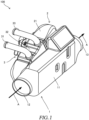
FIG. 1] FIG. 1 is a perspective view of an exhaust heat recovery device according to an embodiment of the present invention as viewed from a front side thereof. - [
FIG. 2] FIG. 2 is a top view of the exhaust heat recovery device shown inFIG. 1 . - [
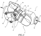
FIG. 3] FIG. 3 is a perspective view of the exhaust heat recovery device shown inFIG. 1 as viewed from a rear side thereof. - [
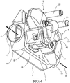
FIG. 4] FIG. 4 is a perspective view of the exhaust heat recovery device shown inFIG. 1 as viewed from a bottom side thereof. - [
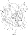
FIG. 5] FIG. 5 is a view illustrating a shaft portion provided in a first flow path member inFIG. 4 . - [
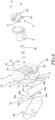
FIG. 6] FIG. 6 is an exploded perspective view of the exhaust heat recovery device shown inFIG. 1 . - [
FIG. 7] FIG. 7 is a schematic view of a VII-VII cross section inFIG. 2 . - [
FIG. 8] FIG. 8 is a view of the exhaust heat recovery device shown inFIG. 1 as viewed from the bottom side, and is a view illustrating a valve mechanism and a drive unit. - [
FIG. 9] FIG. 9 is a schematic view when exhaust gas flows through a first flow path inFIG. 7 . - [
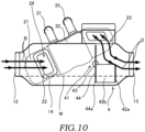
FIG. 10] FIG. 10 is a schematic view when the exhaust gas flows through a second flow path inFIG. 7 . - [
FIG. 11] FIG. 11 is a schematic view of an XI-XI cross section inFIG. 2 , and is a schematic view when the exhaust gas flows through the first flow path. - [
FIG. 12] FIG. 12 is a schematic view when the exhaust gas flows through the second flow path inFIG. 11 . - Hereinafter, an exhaust
heat recovery device 100 according to an embodiment of the present invention will be described with reference to the drawings. - First, an overall configuration of the exhaust
heat recovery device 100 will be described with reference toFIGs. 1 to 4 . -
FIG. 1 is a perspective view of the exhaustheat recovery device 100 as viewed from a front side thereof.FIG. 2 is a top view of the exhaustheat recovery device 100 shown inFIG. 1 .FIG. 3 is a perspective view of the exhaustheat recovery device 100 shown inFIG. 1 as viewed from a rear side thereof.FIG. 4 is a perspective view of the exhaustheat recovery device 100 shown inFIG. 1 as viewed from a bottom side thereof. InFIGs. 1 to 4 , a flow of exhaust gas in a firstflow path member 1 is indicated by an arrow A. - As shown in
FIGs. 1 to 4 , the exhaustheat recovery device 100 includes the firstflow path member 1, a secondflow path member 2, aheat exchange unit 3, anactuator 5 as a drive unit, and abracket 6. Although details will be described later, the exhaustheat recovery device 100 also includes avalve mechanism 4. - As shown in
FIGs. 1 to 4 , the firstflow path member 1 includes amain body 11, afirst inflow port 12, and afirst outflow port 13. - As shown in
FIG. 1 , themain body 11 is formed in a substantially rectangular parallelepiped shape. In themain body 11, thefirst inflow port 12 is opened at one end, and thefirst outflow port 13 is opened at the other end. - The
first inflow port 12 is connected to an upstream side of an exhaust flow path of an engine (not shown). Thefirst outflow port 13 is connected to a downstream side of the exhaust flow path of the engine (not shown). Although details will be described later, themain body 11 has a hollow structure through which the exhaust gas can pass. Accordingly, as indicated by the arrow A inFIGs. 1 to 4 , exhaust gas flowing from the exhaust flow path of the engine can flow into themain body 11 from thefirst inflow port 12, and can flow out from thefirst outflow port 13 to the downstream side of the exhaust flow path (outside of the main body 11). - As shown in
FIGs. 1 to 4 , the secondflow path member 2 is formed in a structure connected to the firstflow path member 1. The secondflow path member 2 is provided adjacent to the firstflow path member 1. The secondflow path member 2 includes theheat exchange unit 3. Although details will be described later, the secondflow path member 2 has a hollow structure through which the exhaust gas can pass. In addition, the hollow structure of the secondflow path member 2 is coupled to the hollow structure of the firstflow path member 1, and the exhaust gas flowing into the firstflow path member 1 can flow into the secondflow path member 2. - As shown in
FIGs. 1 and3 , theheat exchange unit 3 constitutes a part of an outer circumference of amain body 21. Cooling water as a refrigerant flows inside theheat exchange unit 3, and the refrigerant may be a medium such as a liquid or a gas suitable for heat exchange other than the cooling water. When the exhaust gas passes through the secondflow path member 2, heat exchange between the exhaust gas and the cooling water in theheat exchange unit 3 is performed in theheat exchange unit 3. A configuration of theheat exchange unit 3 will be described later in detail. - As shown in
FIG. 3 , in theactuator 5, amain body 52 is inclined and provided at a position of being partially overlapped with the secondflow path member 2 and theheat exchange unit 3 on an outer circumferential side thereof. In addition, theactuator 5 includes adrive shaft 51 extending toward the first flow path member 1 (seeFIG. 8 ). - As shown in
FIG. 4 , thebracket 6 is provided at a position on a bottom side of the secondflow path member 2 and theheat exchange unit 3. - Next, details of the configuration of the exhaust
heat recovery device 100 described above and thevalve mechanism 4 provided in the exhaustheat recovery device 100 will be described with reference toFIGs. 1 to 4 andFIGs. 5 to 8 . -
FIG. 5 is a view illustrating abearing 15 provided in the firstflow path member 1 inFIG. 4 . InFIG. 5 , the flow of the exhaust gas in the firstflow path member 1 is indicated by an arrow A.FIG. 6 is an exploded perspective view of the exhaustheat recovery device 100 shown inFIG. 1 .FIG. 7 is a schematic view of a VII-VII cross section inFIG. 2 .FIG. 8 is a view of the exhaustheat recovery device 100 shown inFIG. 1 as viewed from the bottom side, and is a view illustrating thevalve mechanism 4 and theactuator 5. InFIG. 8 , the flow of the exhaust gas in the firstflow path member 1 is indicated by an arrow A. - First, configurations of the first
flow path member 1 and the secondflow path member 2 will be described in detail. - As shown in
FIG. 7 , the firstflow path member 1 has a hollow structure, and afirst flow path 14 is formed inside the firstflow path member 1. - As shown in
FIG. 7 , the secondflow path member 2 includes themain body 21, asecond inflow port 22, and asecond outflow port 23. Themain body 21 has a hollow structure, and asecond flow path 24 is formed inside themain body 21. In themain body 21, thesecond inflow port 22 is opened at one end side, and thesecond outflow port 23 is opened at the other end side. Opening positions of thesecond inflow port 22 and thesecond outflow port 23 are appropriately changed according to a design of the exhaustheat recovery device 100, and are not limited to positions shown inFIG. 7 . - As shown in
FIG. 7 , thesecond inflow port 22 is connected to the firstflow path member 1 on thefirst inflow port 12 side. Thesecond outflow port 23 is connected to the firstflow path member 1 on afirst outflow port 13 side. Accordingly, thefirst flow path 14 and thesecond flow path 24 communicate with each other. That is, the exhaust gas flowing into themain body 11 from thefirst inflow port 12 can flow into themain body 21 from thesecond inflow port 22. Further, the exhaust gas flowing into themain body 21 from thesecond inflow port 22 can flow out from thesecond outflow port 23 to themain body 11. - In other words, the above configuration is a configuration in which the
second flow path 24 bypasses a part of the first flow path 14 (section between thesecond inflow port 22 and the second outflow port 23). - As shown in
FIG. 7 , thesecond inflow port 22 and thesecond outflow port 23 are connected to the firstflow path member 1 at a position higher than a water immersion line W. Here, the water immersion line W is a line indicating an upper limit of height of a water level at which water does not flow into an inside of the exhaust heat recovery device 100 (inside of the first flow path 14) when the exhaustheat recovery device 100 is immersed in the water. Here, since thefirst inflow port 12 and thefirst outflow port 13 have the same height, the water immersion line W is positioned at lower ends of thefirst inflow port 12 and thefirst outflow port 13. This is because when the height of the water level exceeds the lower ends of thefirst inflow port 12 and thefirst outflow port 13, the water flows into thefirst flow path 14 inside the exhaustheat recovery device 100 from thefirst inflow port 12 and thefirst outflow port 13. - By setting the
second inflow port 22 and thesecond outflow port 23 at a position higher than the water immersion line W, even if the inside of the first flow path member 1 (inside of the first flow path 14) is immersed, it is possible to prevent the water from entering thesecond flow path 24. That is, a decrease in heat recovery efficiency between the exhaust gas in thesecond flow path 24 and cooling water in theheat exchange unit 3 due to water entering thesecond flow path 24 can be prevented. - As shown in
FIG. 7 , the secondflow path member 2 is disposed so as to be inclined with respect to the firstflow path member 1. Specifically, the secondflow path member 2 is disposed so as to be inclined with respect to a flow direction of the exhaust gas in thefirst flow path 14 that flows from thefirst inflow port 12 toward thefirst outflow port 13. More specifically, the secondflow path member 2 is disposed so as to be inclined upward away from thefirst flow path 14 from an upstream side (first inflow port 12 side) toward a downstream side (first outflow port 13 side) in the flow direction of the exhaust gas in thefirst flow path 14. - As shown in
FIG. 5 , since the secondflow path member 2 is integrally joined to the firstflow path member 1 along the firstflow path member 1 without a gap therebetween and is disposed so as to be inclined with respect to the flow direction of the exhaust gas in thefirst flow path 14, a region S (region indicated by a two-dot chain line inFIG. 5 ) is formed in a region on a lateral side of the secondflow path member 2 when viewed in a direction of thedrive shaft 51 of the actuator 5 (when viewed in an axial direction of thedrive shaft 51 of the actuator 5). The bearing 15 for supporting arotation shaft portion 43 of thevalve mechanism 4, which will be described later, is provided in the region S. - The region S can be said to be a region surrounded by a
lower edge portion 2a of the secondflow path member 2, alower edge portion 1a of the firstflow path member 1, and a downstreamside end portion 1b in the flow direction of the exhaust gas in the firstflow path member 1 when the exhaustheat recovery device 100 is viewed in an extending direction of thedrive shaft 51 of the actuator 5 (seeFIG. 5 ). - The
lower edge portion 2a is a portion including an edge of abottom surface 2b of the secondflow path member 2. That is, thelower edge portion 2a can be said to be thebottom surface 2b of the second flow path member 2 (seeFIG. 5 ). - The
lower edge portion 1a is a portion including an edge of abottom surface 1c of the firstflow path member 1. That is, thelower edge portion 1a can be said to be thebottom surface 1c of the first flow path member 1 (seeFIG. 5 ). - The downstream
side end portion 1b is a portion including an edge of aside surface 1d on the downstream side in the flow direction of the exhaust gas in the firstflow path member 1. That is, the downstreamside end portion 1b can be said to be theside surface 1d on the downstream side in the flow direction of the exhaust gas in the first flow path member 1 (seeFIG. 5 ). - That is, a region surrounded by the three surfaces including the respective surfaces (
bottom surface 2b of the secondflow path member 2, thebottom surface 1c of the firstflow path member 1, and theside surface 1d on the downstream side in the flow direction of the exhaust gas in the first flow path member 1) is the region S. In addition, the region S can also be said to be a region surrounded by thebottom surface 2b of the secondflow path member 2 and aside surface 1e of the first flow path member 1 (seeFIG. 5 ). - In other words, the region S can be said to be a region of an outer circumference of the first
flow path member 1 on a secondflow path member 2 side, which is not adjacent to the secondflow path member 2. In addition, it can be said that the bearing 15 disposed in the region S is disposed side by side with the secondflow path member 2 in a vertical direction on the drawing (seeFIG. 5 ) when viewed in a direction ofFIG. 5 . A position of thebearing 15 can be appropriately changed in the region S according to a size of the exhaustheat recovery device 100. - Next, the configuration of the
heat exchange unit 3 incorporated in the secondflow path member 2 will be described in detail. - As shown in
FIGs. 1 to 3 ,5 , and7 , theheat exchange unit 3 includes arefrigerant inflow portion 31, a heat exchangermain body 32, and arefrigerant outflow portion 33. As shown inFIG. 7 , theheat exchange unit 3 is provided at a position higher than the water immersion line W. - That is, the
heat exchange unit 3 is provided at a position where the water level does not reach even when the exhaustheat recovery device 100 is immersed and the water enters thefirst flow path 14. Accordingly, it is possible to prevent theheat exchange unit 3 from being immersed. Therefore, the decrease in the heat recovery efficiency between the exhaust gas in thesecond flow path 24 and the cooling water in theheat exchange unit 3 due to immersion of theheat exchange unit 3 can be prevented. - The
refrigerant inflow portion 31 is a hollow tubular portion that connects a flow path (not shown) through which cooling water before cooling the engine flows and an inside of the heat exchangermain body 32. Therefrigerant inflow portion 31 allows the cooling water serving as a refrigerant supplied from the above flow path to flow to the inside of the heat exchangermain body 32. - As shown in
FIG. 3 , the heat exchangermain body 32 constitutes a part of the outer circumference of themain body 21. The cooling water flowing in from therefrigerant inflow portion 31 flows to the inside of the heat exchangermain body 32. - The
refrigerant outflow portion 33 is a hollow tubular portion that connects the inside of the heat exchangermain body 32 and a flow path (not shown) through which the cooling water is supplied to the engine. Therefrigerant inflow portion 31 allows the cooling water flowing through the inside of the heat exchangermain body 32 to flow out to the above flow path. - When the exhaust gas flows in a portion of the
main body 21 of the secondflow path member 2, which is surrounded by the heat exchanger main body 32 (portion of thesecond flow path 24 which is surrounded by the heat exchanger main body 32), in theheat exchange unit 3 having the above configuration, heat exchange between the exhaust gas and the cooling water flowing through the inside of the heat exchangermain body 32 is performed, and heat of the exhaust gas is moved to the cooling water and recovered. - Here, the
second inflow port 22 through which the exhaust gas flows into thesecond flow path 24 and thesecond outflow port 23 through which the exhaust gas flows out from thesecond flow path 24 are provided at positions higher than the water immersion line W (seeFIG. 7 ). As a result, it is possible to prevent theheat exchange unit 3 from being immersed. Therefore, obstruction of the flow of the exhaust gas in thesecond flow path 24 due to the immersion of theheat exchange unit 3 can be prevented. Accordingly, the decrease in the heat recovery efficiency between the exhaust gas and the cooling water in theheat exchange unit 3 can be prevented. - Next, the
valve mechanism 4 will be described. - As shown in
FIGs. 6 to 8 , the exhaustheat recovery device 100 includes thevalve mechanism 4. Thevalve mechanism 4 includes abutterfly valve 41 and ashutter portion 42. Thebutterfly valve 41 includes therotation shaft portion 43 and avalve body 44. As shown inFIG. 6 , thevalve mechanism 4 is incorporated in the firstflow path member 1 when dividedcomponents 1A and 1B of the first flow path member are combined. - As shown in
FIG. 8 , in thevalve mechanism 4, one end (tip end portion) 43a of therotation shaft portion 43 is supported by thebearing 15. Accordingly, thevalve mechanism 4 is rotatably supported in thefirst flow path 14. - As shown in
FIG. 8 , an oneend 43a side of therotation shaft portion 43 protrudes to an outside (corresponding to the region S inFIG. 5 ) of the firstflow path member 1. The oneend 43a of therotation shaft portion 43 is coupled to thedrive shaft 51 of theactuator 5, which will be described later, via acoupling 50. Specifically, therotation shaft portion 43 is inserted into thebearing 15, and the oneend 43a of therotation shaft portion 43 protrudes from a tip end of thebearing 15. A spring is incorporated between the bearing 15 and thecoupling 50 so as to surround the oneend 43a of therotation shaft portion 43, and thecoupling 50 is pushed up by using an elastic force of the spring. Accordingly, a claw at a tip end portion of thedrive shaft 51 is inserted into an insertion hole of thecoupling 50, and thecoupling 50 is coupled to thedrive shaft 51 in a state where thecoupling 50 receives a repulsive force of the spring. That is, therotation shaft portion 43 is rotatably coupled to thedrive shaft 51 through a mechanism of thecoupling 50. In addition, a position where the oneend 43a of therotation shaft portion 43 and thedrive shaft 51 are coupled via thecoupling 50 is, for example, within the region S in the present embodiment (seeFIG. 5 ). Further, in a base portion of therotation shaft portion 43, a seal member for preventing leakage of gas or the like is provided on an entire circumference between the base portion and thebearing 15. - As a result, as compared with a case where the entire
rotation shaft portion 43 is disposed inside the firstflow path member 1, in therotating shaft portion 43 of the present embodiment, a range affected by the heat of the exhaust gas flowing in thefirst flow path 14 is small due to a structure in which connection with thedrive shaft 51 is performed in the region S. Accordingly, influence of the heat of the exhaust gas on the rotation shaft portion 43 (or drive shaft 51) can be reduced. Therefore, durability of the exhaustheat recovery device 100 can be improved. - As shown in
FIGs. 6 and8 , thevalve body 44 of thebutterfly valve 41 is provided on theother end 43b side of therotation shaft portion 43. Thevalve body 44 of thebutterfly valve 41 is a plate-shaped portion formed to have a length and a width that are large enough to close thefirst flow path 14. Thevalve body 44 rotates together with therotation shaft portion 43, and opens and closes thefirst flow path 14 according to a movement position. - As shown in
FIGs. 6 and7 , theshutter portion 42 is provided on an oneend 44a side of thevalve body 44. - The
shutter portion 42 is a portion formed in a shape capable of closing thesecond outflow port 23. In the present embodiment, theshutter portion 42 includes a shuttermain body 42a formed to have a length and a width that are large enough to close thesecond outflow port 23, andcoupling portions 42b that couple the shuttermain body 42a and the oneend 44a side of thevalve body 44 to support the shuttermain body 42a. As shown inFIG. 6 , in the present embodiment, the shuttermain body 42a is supported by twocoupling portions 42b. The number of thecoupling portions 42b is not limited to the number shown inFIG. 6 as long as the shuttermain body 42a can be supported. For example, the number of thecoupling portions 42b may be one or may be three or more. - The
shutter portion 42 rotationally moves with the rotation of thevalve body 44, and opens and closes thesecond outflow port 23 according to a movement position. That is, thevalve mechanism 4 can simultaneously move thevalve body 44 of thebutterfly valve 41 and theshutter portion 42 to open and close thefirst flow path 14 and thesecond outflow port 23 by rotating only therotation shaft portion 43. As a result, the number of components can be reduced as compared with a case where the butterfly valve 41 (valve body 44) and theshutter portion 42 are rotationally moved by separate mechanisms. In addition, since it is possible to prevent the exhaust gas from flowing into thesecond flow path 24 without opening thesecond flow path 24 during non-heat recovery (state where thevalve mechanism 4 is in a position shown inFIG. 9 . Details will be described later), it is possible to improve performance of the exhaustheat recovery device 100 during the non-heat recovery. - The bearing 15 that supports the
rotation shaft portion 43 of thevalve mechanism 4 is provided adjacent to the firstflow path member 1 and is disposed so as to be inclined with respect to the flow direction of the exhaust gas in thefirst flow path 14, so that thebearing 15 is provided in the region S formed on the lateral side of the secondflow path member 2 when viewed in the direction of thedrive shaft 51 of the actuator 5 (seeFIG. 5 ). That is, therotation shaft portion 43 is also disposed at a position in the region S. The region S is formed by disposing the secondflow path member 2 so as to be inclined with respect to the flow direction of the exhaust gas in thefirst flow path 14. That is, by disposing therotation shaft portion 43 in the region S, the rotation shaft portion 43 (valve mechanism 4) can be disposed on the upstream side in the flow direction of the exhaust gas in thefirst flow path 14 as compared with a case where the secondflow path member 2 is not disposed so as to be inclined. Accordingly, the entire exhaustheat recovery device 100 can be made compact in the flow direction of the exhaust gas in thefirst flow path 14. - As shown in
FIG. 8 , only the oneend 43a side of therotation shaft portion 43 is supported by thebearing 15. That is, therotation shaft portion 43 has a cantilever structure. Here, the oneend 43a side of therotation shaft portion 43 supported by thebearing 15 is provided longer so as to be supported by a cantilever structure (seeFIG. 6 ). - As a result, as compared with a case where the
rotation shaft portion 43 is supported on the oneend 43a side and a bearing structure is provided on theother end 43b side (that is, not a cantilever structure and therotation shaft portion 43 is supported at two points), the range affected by the heat of the exhaust gas flowing in thefirst flow path 14 is smaller in therotation shaft portion 43 according to the present embodiment. Accordingly, the influence of the heat of the exhaust gas on the valve mechanism 4 (rotation shaft portion 43) and thebearing 15 can be reduced. Therefore, the durability of the exhaustheat recovery device 100 can be improved. - Next, a configuration of the
actuator 5 will be described in detail. As shown inFIGs. 2 to 4 ,6 , and8 , theactuator 5 includes thedrive shaft 51, themain body 52, and aconnector 53. - As shown in
FIG. 8 , thedrive shaft 51 extends toward theside surface 1e of the firstflow path member 1. Thedrive shaft 51 is coupled (connected) to the oneend 43a of therotation shaft portion 43 in the region S via the coupling 50 (seeFIGs. 5 and8 ). Specifically, thedrive shaft 51 is connected to the oneend 43a of therotation shaft portion 43 protruding to the outside of the firstflow path member 1 in the region S. - The
main body 52 has a mechanism for rotationally driving thedrive shaft 51. Theconnector 53 is coupled to a power supply unit (not shown) by an electric wire. Themain body 52 rotationally drives thedrive shaft 51 according to electric power supplied by the power supply unit through theconnector 53 and control of a control unit (not shown). - When the
drive shaft 51 rotates, therotation shaft portion 43 coupled to thedrive shaft 51 rotates. Thebutterfly valve 41 and theshutter portion 42 of thevalve mechanism 4 are rotationally moved in response to the rotation of therotation shaft portion 43. - As shown in
FIG. 3 , themain body 52 is disposed with the secondflow path member 2 interposed between themain body 52 and the firstflow path member 1. In addition, a part of themain body 52 is fixed to an exterior (housing) of the heat exchangermain body 32 incorporated in the secondflow path member 2, and the other part is fixed to thebracket 6. That is, themain body 52 is disposed at least at a position away from thefirst flow path 14. Therefore, since themain body 52 is provided at the above position, themain body 52 is less likely to be affected by the heat of the exhaust gas flowing in thefirst flow path 14. Accordingly, durability of theactuator 5 can be improved. Further, in the present embodiment, by providing theactuator 5 at a position corresponding to the heat exchangermain body 32, it is possible to prevent the influence of the heat of exhaust gas flowing through the secondflow path member 2. Theactuator 5 may be fixed only to the heat exchangermain body 32. - When the
main body 52 has a size that falls within the region S, themain body 52 may be disposed in the region S. In this case, the exhaustheat recovery device 100 can be made compact in a direction (short-length direction) orthogonal to the flow direction (longitudinal direction) of the exhaust gas in thefirst flow path 14. Here, when themain body 52 is disposed in the region S, it is desirable to provide a heat insulating material or a space at least between the firstflow path member 1 and themain body 52. In this case, it is also desirable to fix themain body 52 to a position corresponding to theheat exchange unit 3 in the secondflow path member 2. This is to prevent themain body 52 from being affected by the heat of the exhaust gas flowing in the firstflow path member 1 and the secondflow path member 2. - The actuator 5 (main body 52) is disposed so as to be inclined (see
FIGs. 3 and4 ). Specifically, the actuator 5 (main body 52) is disposed so as to be inclined with respect to the flow direction of the exhaust gas in the first flow path 14 (arrows A inFIGs. 3 and4 ) along the firstflow path member 1. - According to the above arrangement, a part of the
main body 52 is adjacent to asecond outflow port 23 side of the secondflow path member 2 and an outer circumferential surface of the heat exchange unit 3 (seeFIGs. 3 and4 ). - Here, since the exhaust gas flowing in a portion of the second
flow path member 2 on thesecond outflow port 23 side is already heat-recovered by theheat exchange unit 3, a temperature thereof is low. Therefore, a temperature of an outer circumferential surface of the portion of the secondflow path member 2 on thesecond outflow port 23 side also decreases. In addition, a temperature of the outer circumferential surface of theheat exchange unit 3 also decreases by the heat recovery. - Therefore, since the
main body 52 is provided at the above position, influence of the heat of the exhaust gas flowing in thesecond flow path 24 is suppressed. Accordingly, the durability of theactuator 5 can be improved. Therefore, the durability of the exhaustheat recovery device 100 can be improved. - As shown in
FIGs. 3 and4 , theconnector 53 is also inclined. Accordingly, even if the water enters theconnector 53, the water can be discharged to the outside. That is, it is possible to prevent the water from accumulating in theconnector 53. - The bearing 15 that supports the
rotation shaft portion 43 of thevalve mechanism 4 is provided adjacent to the firstflow path member 1 and is disposed so as to be inclined with respect to the flow direction of the exhaust gas in thefirst flow path 14, so that thebearing 15 is provided in the region S formed on the lateral side of the secondflow path member 2 when viewed in the direction of thedrive shaft 51 of the actuator 5 (seeFIG. 5 ). That is, thedrive shaft 51 connected to therotation shaft portion 43 is also disposed in the region S (seeFIGs. 5 and8 ). The region S is generated by disposing the secondflow path member 2 so as to be inclined with respect to the flow direction of the exhaust gas in thefirst flow path 14. That is, by disposing thedrive shaft 51 in the region S (connecting thedrive shaft 51 to therotation shaft portion 43 in the region S), thedrive shaft 51 and theactuator 5 as a whole can be disposed on the upstream side in the flow direction of the exhaust gas in thefirst flow path 14 as compared with a case where the secondflow path member 2 is not disposed so as to be inclined. Accordingly, the entire exhaustheat recovery device 100 can be made compact in the flow direction (longitudinal direction) of the exhaust gas in thefirst flow path 14. - As described above, the exhaust
heat recovery device 100 has a configuration in which thedrive shaft 51 extends toward the firstflow path member 1 and is connected to therotation shaft portion 43 in the region S formed by disposing the secondflow path member 2 so as to be inclined with respect to the firstflow path member 1, and has a configuration in which theactuator 5 is disposed with the secondflow path member 2 interposed between theactuator 5 and the firstflow path member 1. By adopting the above two configurations, the exhaustheat recovery device 100 can be made compact in the flow direction (longitudinal direction) of the exhaust gas in thefirst flow path 14, and the durability of the actuator 5 (and hence the durability of the exhaust heat recovery device 100) can be improved by suppressing the influence of the heat of the exhaust gas on theactuator 5. - Next, the
bracket 6 will be described. - As shown in
FIGs. 4 and6 , the exhaustheat recovery device 100 further includes thebracket 6 that surrounds outsides of thedrive shaft 51, thebearing 15, and therotation shaft portion 43. By providing thebracket 6, thedrive shaft 51, thebearing 15, and therotation shaft portion 43 can be protected from flying objects such as flying stones. In the present embodiment, thebracket 6 is provided on the first flow path member 1 (seeFIGs. 4 and6 ). Thebracket 6 may be provided on the secondflow path member 2. - Next, the heat recovery performed by the exhaust
heat recovery device 100 having the above configuration will be described with reference toFIGs. 9 to 12 . -
FIG. 9 is a schematic view when the exhaust gas flows through thefirst flow path 14 inFIG. 7 .FIG. 10 is a schematic view when the exhaust gas flows through thesecond flow path 24 inFIG. 7 .FIG. 11 is a schematic view of an XI-XI cross section inFIG. 2 , and is a schematic view when the exhaust gas flows through thefirst flow path 14.FIG. 12 is a schematic view when the exhaust gas flows through thesecond flow path 24 inFIG. 11 . - First, the non-heat recovery (for example, a case where warm-up of the engine is not necessary) as a case where the heat recovery from the exhaust gas is not necessary will be described with reference to
FIGs. 9 and11 . In this case, the control unit rotationally drives thedrive shaft 51 to rotate therotation shaft portion 43, thereby switching thevalve body 44 and theshutter portion 42 of thevalve mechanism 4 to positions shown inFIG. 9 . Therefore, thevalve mechanism 4 is switched such that thevalve body 44 of thebutterfly valve 41 opens thefirst flow path 14 and theshutter portion 42 closes thesecond outflow port 23. - As shown in
FIG. 9 , when thefirst flow path 14 is opened and thesecond outflow port 23 is closed, the exhaust gas flowing from the exhaust flow path passes through the inside of themain body 11 from thefirst inflow port 12 as indicated by an arrow A, and flows out from thefirst outflow port 13 to the downstream side of the exhaust flow path (outside of the main body 11). In addition, when thesecond outflow port 23 is closed, the exhaust gas does not flow in the main body 21 (in the second flow path 24) as shown inFIG. 11 . Therefore, the heat exchange between the exhaust gas and the cooling water flowing through theheat exchange unit 3 is not performed. That is, the exhaust gas is discharged to the outside without being heat-recovered. - Next, a case where the heat recovery from the exhaust gas is necessary (for example, a case where warm-up of the engine is necessary) will be described with reference to
FIGs. 10 and12 . In this case, the control unit rotationally drives thedrive shaft 51 to rotate therotation shaft portion 43, thereby switching thevalve body 44 and theshutter portion 42 of thevalve mechanism 4 to positions shown inFIG. 10 . Therefore, thevalve mechanism 4 is switched such that thevalve body 44 of thebutterfly valve 41 closes thefirst flow path 14 and theshutter portion 42 opens thesecond outflow port 23. - As shown in
FIG. 10 , when thefirst flow path 14 is closed and thesecond outflow port 23 is opened, the exhaust gas flowing from the exhaust flow path passes through thesecond inflow port 22 from thefirst inflow port 12 as indicated by an arrow B, and flows into the main body 21 (second flow path 24) of the secondflow path member 2. As shown inFIG. 12 , the exhaust gas flowing into themain body 21 from thesecond inflow port 22 flows in a direction of an arrow C. Here, when the exhaust gas flows in the heat exchangermain body 32 in themain body 21, the heat exchange between the exhaust gas and the cooling water flowing through the heat exchange unit 3 (cooling water flowing in a direction of a broken line arrow X inFIG. 12 ) is performed. That is, the cooling water is warmed. The warmed cooling water flows out from therefrigerant outflow portion 33 and is supplied to the engine, so that the engine can be warmed up. - As indicated by arrows C and D in
FIGs. 10 and12 , the exhaust gas whose heat is recovered passes through thesecond outflow port 23 and flows out from thefirst outflow port 13 to the downstream side of the exhaust flow path (outside of the main body 11). - According to the above embodiment, the following effects are exerted.
- The exhaust
heat recovery device 100 that recovers heat of exhaust gas discharged from an engine by heat exchange with a refrigerant includes: the firstflow path member 1 in which thefirst flow path 14 through which the exhaust gas flows is formed; the secondflow path member 2 which is provided adjacent to the firstflow path member 1, in which thesecond flow path 24 that bypasses a part of thefirst flow path 14 is formed, and which includes theheat exchange unit 3 configured to perform heat exchange between the exhaust gas flowing in thesecond flow path 24 and the refrigerant; thevalve mechanism 4 configured to switch between opening and closing of thefirst flow path 14 and thesecond flow path 24 by rotation of therotation shaft portion 43 disposed in the firstflow path member 1; and thedrive unit 5 which includes thedrive shaft 51 configured to rotate therotation shaft portion 43. The secondflow path member 2 is disposed so as to be inclined with respect to a flow direction of the exhaust gas in thefirst flow path 14, and thedrive shaft 51 extends toward the firstflow path member 1 and is connected to therotation shaft portion 43 in the region S formed on a lateral side of the secondflow path member 2 when viewed in an axial direction of thedrive shaft 51 of theactuator 5 by disposing the secondflow path member 2 so as to be inclined with respect to the firstflow path member 1. - The second
flow path member 2 is disposed so as to be inclined away from thefirst flow path 14 from an upstream side to a downstream side in the flow direction of the exhaust gas in thefirst flow path 14. - The
drive shaft 51 is disposed in a region surrounded by thelower edge portion 2a of the secondflow path member 2, thelower edge portion 1a of the firstflow path member 1, and the downstreamside end portion 1b in the flow direction of the exhaust gas in the firstflow path member 1 when viewed in the axial direction of thedrive shaft 51 of theactuator 5. - According to these configurations, the rotation shaft portion 43 (valve mechanism 4) and the drive shaft 51 (actuator 5) can be disposed on the upstream side in the flow direction of the exhaust gas in the
first flow path 14. Accordingly, the entire exhaustheat recovery device 100 can be made compact in the flow direction (longitudinal direction) of the exhaust gas in thefirst flow path 14. - The
drive shaft 51 is connected to the oneend 43a of therotation shaft portion 43, which protrudes to an outside of the firstflow path member 1, in the region S. - The
rotation shaft portion 43 has a cantilever structure in which only the oneend 43a is supported. - According to these configurations, it is possible to reduce the influence of the heat of the exhaust gas on the valve mechanism 4 (rotation shaft portion 43). Therefore, the durability of the exhaust
heat recovery device 100 can be improved. - The
actuator 5 is disposed with the secondflow path member 2 interposed between theactuator 5 and the firstflow path member 1. - The
actuator 5 is disposed along thefirst flow path 14 so as to be inclined with respect to the flow direction of the exhaust gas in thefirst flow path 14. - According to these configurations, it is possible to suppress the influence of the heat of the exhaust gas on the
actuator 5. That is, the durability of theactuator 5 can be improved. Therefore, the durability of the exhaustheat recovery device 100 can be improved. - The exhaust
heat recovery device 100 further includes thebracket 6 surrounding an outside of thedrive shaft 51. - According to this configuration, the
drive shaft 51 can be protected from flying objects such as flying stones. - The first
flow path member 1 includes thefirst inflow port 12 through which the exhaust gas flows in and thefirst outflow port 13 through which the exhaust gas flowing in from thefirst inflow port 12 flows out, and the secondflow path member 2 includes thesecond inflow port 22 connected to the firstflow path member 1 on thefirst inflow port 12 side and thesecond outflow port 23 connected to the firstflow path member 1 on thefirst outflow port 13 side. Thevalve mechanism 4 further includes: thebutterfly valve 41 configured to open and close thefirst flow path 14; and theshutter portion 42 configured to close thesecond outflow port 23 when thebutterfly valve 41 opens thefirst flow path 14 and open thesecond outflow port 23 when thebutterfly valve 41 closes thefirst flow path 14. - According to this configuration, the
first flow path 14 and thesecond outflow port 23 can be opened and closed by integrally moving thebutterfly valve 41 and theshutter portion 42. That is, the number of components can be reduced as compared with a case where the butterfly valve 41 (valve body 44) and theshutter portion 42 are rotationally moved by separate mechanisms. In addition, since thesecond flow path 24 is not opened during the non-heat recovery and it is possible to prevent the exhaust gas from flowing into thesecond flow path 24, it is possible to improve the performance of the exhaustheat recovery device 100 during the non-heat recovery. - The
heat exchange unit 3 is provided at a position higher than the water immersion line W positioned at the lower ends of thefirst inflow port 12 and thefirst outflow port 13. - The
second inflow port 22 and thesecond outflow port 23 are provided at positions higher than the water immersion line W. - According to these configurations, it is possible to prevent the
heat exchange unit 3 from being immersed. Therefore, obstruction of the flow of the exhaust gas in thesecond flow path 24 due to the immersion of theheat exchange unit 3 can be prevented. Accordingly, it is possible to prevent the decrease in the heat recovery efficiency between the exhaust gas and the cooling water in theheat exchange unit 3. - The
main body 52 of the actuator (drive unit) 5 is fixed to an exterior (housing) of the heat exchangermain body 32 of theheat exchange unit 3. - According to this configuration, the
main body 52 of theactuator 5 is less likely to be affected by the heat of the exhaust gas flowing through the firstflow path member 1 and the heat of the exhaust gas flowing through the secondflow path member 2, and thus the durability of theactuator 5 can be ensured, and cost can be reduced since no special heat countermeasure for theactuator 5 is required. - Although the embodiments of the present invention have been described above, the above-mentioned embodiments are merely a part of application examples of the present invention, and do not mean that the technical scope of the present invention is limited to the specific configurations of the above-mentioned embodiments.
- The present application claims priority under
Japanese Patent Application No. 2020-094806 filed to the Japan Patent Office on May 29, 2020
Claims (12)
- An exhaust heat recovery device configured to recover heat of exhaust gas discharged from an engine by heat exchange with a refrigerant, the exhaust heat recovery device comprising:a first flow path member in which a first flow path through which the exhaust gas flows is formed;a second flow path member which is provided adjacent to the first flow path member, in which a second flow path that bypasses a part of the first flow path is formed, and which includes a heat exchange unit configured to perform heat exchange between the exhaust gas flowing in the second flow path and the refrigerant;a valve mechanism configured to switch between opening and closing of the first flow path and the second flow path by rotation of a rotation shaft portion disposed in the first flow path member; anda drive unit which includes a drive shaft configured to rotate the rotation shaft portion, whereinthe second flow path member is disposed so as to be inclined with respect to a flow direction of the exhaust gas in the first flow path, andthe drive shaft extends toward the first flow path member and is connected to the rotation shaft portion in a region formed on a lateral side of the second flow path member when viewed in an axial direction of the drive shaft of the drive unit by disposing the second flow path member so as to be inclined with respect to the first flow path member.
- The exhaust heat recovery device according to claim 1, wherein
the drive unit is disposed with the second flow path member interposed between the drive unit and the first flow path member. - The exhaust heat recovery device according to claim 1 or 2, wherein
the drive shaft is connected to one end of the rotation shaft portion, which protrudes to an outside of the first flow path member, in the region. - The exhaust heat recovery device according to any one of claims 1 to 3, wherein
the second flow path member is disposed so as to be inclined away from the first flow path from an upstream side to a downstream side in the flow direction of the exhaust gas in the first flow path. - The exhaust heat recovery device according to any one of claims 1 to 3, whereinthe second flow path member is disposed so as to be inclined upward away from the first flow path from an upstream side to a downstream side in the flow direction of the exhaust gas in the first flow path, andthe drive shaft is disposed in a region surrounded by a lower edge portion of the second flow path member, a lower edge portion of the first flow path member, and a downstream side end portion in the flow direction of the exhaust gas in the first flow path member when viewed in the axial direction of the drive shaft of the drive unit.
- The exhaust heat recovery device according to any one of claims 1 to 5, wherein
the rotation shaft portion has a cantilever structure in which only the one end is supported. - The exhaust heat recovery device according to any one of claims 1 to 6, wherein
the drive unit is disposed along the first flow path member so as to be inclined with respect to the flow direction of the exhaust gas in the first flow path. - The exhaust heat recovery device according to any one of claims 1 to 7, further comprising:
a bracket surrounding an outer side of the drive shaft. - The exhaust heat recovery device according to any one of claims 1 to 8, whereinthe first flow path member includes a first inflow port through which the exhaust gas flows in and a first outflow port through which the exhaust gas flowing in from the first inflow port flows out,the second flow path member includes a second inflow port connected to the first flow path member on a first inflow port side and a second outflow port connected to the first flow path member on a first outflow port side, andthe valve mechanism includes:a butterfly valve configured to open and close the first flow path; anda shutter portion configured to close the second outflow port when the butterfly valve opens the first flow path and open the second outflow port when the butterfly valve closes the first flow path.
- The exhaust heat recovery device according to any one of claims 1 to 8, whereinthe first flow path member includes a first inflow port through which the exhaust gas flows in, and a first outflow port through which the exhaust gas flowing in from the first inflow port flows out,the second flow path member includes a second inflow port connected to the first flow path member on a first inflow port side and a second outflow port connected to the first flow path member on a first outflow port side, andthe heat exchange unit is provided at a position higher than a water immersion line at lower ends of the first inflow port and the first outflow port.
- The exhaust heat recovery device according to claim 10, wherein
the second inflow port and the second outflow port are provided at positions higher than the water immersion line. - The exhaust heat recovery device according to any one of claims 1 to 11, wherein
a main body of the drive unit is fixed to a heat exchanger main body of the heat exchange unit.
Applications Claiming Priority (2)
| Application Number | Priority Date | Filing Date | Title |
|---|---|---|---|
| JP2020094806A JP6752389B1 (en) | 2020-05-29 | 2020-05-29 | Exhaust heat recovery device |
| PCT/JP2021/020078 WO2021241655A1 (en) | 2020-05-29 | 2021-05-26 | Exhaust heat recovery device |
Publications (3)
| Publication Number | Publication Date |
|---|---|
| EP4159987A1 true EP4159987A1 (en) | 2023-04-05 |
| EP4159987A4 EP4159987A4 (en) | 2023-11-01 |
| EP4159987B1 EP4159987B1 (en) | 2024-08-28 |
Family
ID=72333525
Family Applications (1)
| Application Number | Title | Priority Date | Filing Date |
|---|---|---|---|
| EP21812567.2A Active EP4159987B1 (en) | 2020-05-29 | 2021-05-26 | Exhaust heat recovery device |
Country Status (5)
| Country | Link |
|---|---|
| US (1) | US11703018B1 (en) |
| EP (1) | EP4159987B1 (en) |
| JP (1) | JP6752389B1 (en) |
| CN (1) | CN115667684B (en) |
| WO (1) | WO2021241655A1 (en) |
Families Citing this family (2)
| Publication number | Priority date | Publication date | Assignee | Title |
|---|---|---|---|---|
| JP2025014758A (en) | 2023-07-19 | 2025-01-30 | マレリ株式会社 | Exhaust Heat Recovery Device |
| JP2025014767A (en) | 2023-07-19 | 2025-01-30 | マレリ株式会社 | Exhaust Heat Recovery Device |
Family Cites Families (16)
| Publication number | Priority date | Publication date | Assignee | Title |
|---|---|---|---|---|
| FR2776015B1 (en) * | 1998-03-11 | 2000-08-11 | Ecia Equip Composants Ind Auto | HEAT EXCHANGER EXHAUST MEMBER |
| DE102004045021B4 (en) * | 2004-09-15 | 2013-07-11 | Behr Gmbh & Co. Kg | Heat exchanger for internal combustion engines |
| US9027326B2 (en) * | 2011-04-13 | 2015-05-12 | Ford Global Technologies, Llc | Vehicle exhaust heat recovery system |
| FR2981701A1 (en) * | 2011-10-20 | 2013-04-26 | Valeo Sys Controle Moteur Sas | EXHAUST GAS CIRCULATION VALVE OF AN ENGINE, IN PARTICULAR A MOTOR VEHICLE ENGINE |
| JP2014530985A (en) * | 2011-10-24 | 2014-11-20 | ボルボ コンストラクションイクイップメント アーベー | Construction equipment fuel-saving control system |
| US8959904B2 (en) * | 2012-05-24 | 2015-02-24 | Ford Global Technologies, Llc | Method to control and diagnose an exhaust gas heat exchanger |
| CA2933269A1 (en) * | 2013-12-16 | 2015-06-25 | Dana Canada Corporation | Heat recovery device with standoff heat exchanger mount |
| JP6170842B2 (en) | 2014-02-05 | 2017-07-26 | 株式会社三五 | Exhaust heat recovery device |
| KR101708777B1 (en) * | 2015-09-10 | 2017-02-21 | 세종공업 주식회사 | Exhaust heat recovery device having preventing vortex function |
| JP2018071414A (en) * | 2016-10-28 | 2018-05-10 | アイシン高丘株式会社 | Exhaust heat recovery device |
| EP3339618A1 (en) * | 2016-12-20 | 2018-06-27 | Borgwarner Emissions Systems Spain, S.L.U. | Valve for building a compact heat recovery unit |
| FR3062416A1 (en) * | 2017-01-27 | 2018-08-03 | Faurecia Systemes D'echappement | EXHAUST GAS TREATMENT DEVICE, EXHAUST LINE AND METHOD OF MANUFACTURING THE SAME |
| FR3063306B1 (en) * | 2017-02-27 | 2019-04-12 | Faurecia Systemes D'echappement | ASSEMBLY WITH A COOLING DRIVE SHAFT VALVE FOR EXHAUST LINE |
| JP6390770B2 (en) * | 2017-09-06 | 2018-09-19 | トヨタ自動車株式会社 | Waste heat recovery unit structure |
| EP3462003A1 (en) * | 2017-09-29 | 2019-04-03 | Borgwarner Emissions Systems Spain, S.L.U. | Heat recovery system |
| JP2020094806A (en) | 2018-12-10 | 2020-06-18 | 株式会社村田製作所 | Data analyzer |
-
2020
- 2020-05-29 JP JP2020094806A patent/JP6752389B1/en active Active
-
2021
- 2021-05-26 WO PCT/JP2021/020078 patent/WO2021241655A1/en not_active Ceased
- 2021-05-26 CN CN202180037937.4A patent/CN115667684B/en active Active
- 2021-05-26 EP EP21812567.2A patent/EP4159987B1/en active Active
- 2021-05-26 US US17/928,147 patent/US11703018B1/en active Active
Also Published As
| Publication number | Publication date |
|---|---|
| US11703018B1 (en) | 2023-07-18 |
| CN115667684B (en) | 2025-04-15 |
| JP6752389B1 (en) | 2020-09-09 |
| WO2021241655A1 (en) | 2021-12-02 |
| EP4159987A4 (en) | 2023-11-01 |
| US20230213006A1 (en) | 2023-07-06 |
| CN115667684A (en) | 2023-01-31 |
| EP4159987B1 (en) | 2024-08-28 |
| JP2021188567A (en) | 2021-12-13 |
Similar Documents
| Publication | Publication Date | Title |
|---|---|---|
| US11703018B1 (en) | Exhaust heat recovery device | |
| JP5623123B2 (en) | Exhaust heat recovery device | |
| KR101894452B1 (en) | Active Air Flap | |
| CN105189952A (en) | Heat recovery device | |
| KR20230100071A (en) | Active air flap device for vehicle | |
| JP2004190693A (en) | Flow passage switching valve | |
| JP2015183639A (en) | Exhaust heat recovery device | |
| ES2871879T3 (en) | Heat recovery component for an exhaust gas system | |
| KR20210056794A (en) | Vehicle front end structure | |
| JP5074317B2 (en) | Flow path switching valve | |
| KR101399417B1 (en) | Bypass valve assembly for egr cooler | |
| JP5698941B2 (en) | Exhaust heat recovery device | |
| CN221417933U (en) | Air flap device for vehicle | |
| JP2021024324A (en) | Shutter apparatus | |
| JP5278458B2 (en) | Exhaust gas recirculation device | |
| CN110997384B (en) | Air door device | |
| JPH09158724A (en) | Circulating water passage structure for vehicle | |
| KR101003517B1 (en) | Variable Intake of Engine | |
| KR101391728B1 (en) | Valve control unit and exhaust heat recovery device having the same | |
| CN118008883B (en) | Radiator fan, radiator system and radiator control method of vehicle | |
| CN121532558A (en) | Waste gas heat recovery device | |
| KR20130057109A (en) | Active air flap apparatus for vehicle | |
| WO2025018029A1 (en) | Exhaust heat recovery device | |
| JP2006057579A (en) | Waste heat recovery device | |
| JP2016108970A (en) | Exhaust heat recovery device |
Legal Events
| Date | Code | Title | Description |
|---|---|---|---|
| STAA | Information on the status of an ep patent application or granted ep patent |
Free format text: STATUS: THE INTERNATIONAL PUBLICATION HAS BEEN MADE |
|
| PUAI | Public reference made under article 153(3) epc to a published international application that has entered the european phase |
Free format text: ORIGINAL CODE: 0009012 |
|
| STAA | Information on the status of an ep patent application or granted ep patent |
Free format text: STATUS: REQUEST FOR EXAMINATION WAS MADE |
|
| 17P | Request for examination filed |
Effective date: 20221123 |
|
| AK | Designated contracting states |
Kind code of ref document: A1 Designated state(s): AL AT BE BG CH CY CZ DE DK EE ES FI FR GB GR HR HU IE IS IT LI LT LU LV MC MK MT NL NO PL PT RO RS SE SI SK SM TR |
|
| DAV | Request for validation of the european patent (deleted) | ||
| DAX | Request for extension of the european patent (deleted) | ||
| A4 | Supplementary search report drawn up and despatched |
Effective date: 20230928 |
|
| RIC1 | Information provided on ipc code assigned before grant |
Ipc: F01N 3/02 20060101ALI20230922BHEP Ipc: F01N 13/08 20100101ALI20230922BHEP Ipc: F01N 5/02 20060101AFI20230922BHEP |
|
| GRAP | Despatch of communication of intention to grant a patent |
Free format text: ORIGINAL CODE: EPIDOSNIGR1 |
|
| STAA | Information on the status of an ep patent application or granted ep patent |
Free format text: STATUS: GRANT OF PATENT IS INTENDED |
|
| INTG | Intention to grant announced |
Effective date: 20240621 |
|
| GRAS | Grant fee paid |
Free format text: ORIGINAL CODE: EPIDOSNIGR3 |
|
| GRAA | (expected) grant |
Free format text: ORIGINAL CODE: 0009210 |
|
| STAA | Information on the status of an ep patent application or granted ep patent |
Free format text: STATUS: THE PATENT HAS BEEN GRANTED |
|
| AK | Designated contracting states |
Kind code of ref document: B1 Designated state(s): AL AT BE BG CH CY CZ DE DK EE ES FI FR GB GR HR HU IE IS IT LI LT LU LV MC MK MT NL NO PL PT RO RS SE SI SK SM TR |
|
| P01 | Opt-out of the competence of the unified patent court (upc) registered |
Free format text: CASE NUMBER: APP_42508/2024 Effective date: 20240718 |
|
| REG | Reference to a national code |
Ref country code: CH Ref legal event code: EP |
|
| REG | Reference to a national code |
Ref country code: DE Ref legal event code: R096 Ref document number: 602021018070 Country of ref document: DE |
|
| REG | Reference to a national code |
Ref country code: IE Ref legal event code: FG4D |
|
| REG | Reference to a national code |
Ref country code: LT Ref legal event code: MG9D |
|
| PG25 | Lapsed in a contracting state [announced via postgrant information from national office to epo] |
Ref country code: NO Free format text: LAPSE BECAUSE OF FAILURE TO SUBMIT A TRANSLATION OF THE DESCRIPTION OR TO PAY THE FEE WITHIN THE PRESCRIBED TIME-LIMIT Effective date: 20241128 |
|
| REG | Reference to a national code |
Ref country code: AT Ref legal event code: MK05 Ref document number: 1718155 Country of ref document: AT Kind code of ref document: T Effective date: 20240828 |
|
| PG25 | Lapsed in a contracting state [announced via postgrant information from national office to epo] |
Ref country code: NL Free format text: LAPSE BECAUSE OF FAILURE TO SUBMIT A TRANSLATION OF THE DESCRIPTION OR TO PAY THE FEE WITHIN THE PRESCRIBED TIME-LIMIT Effective date: 20240828 Ref country code: PL Free format text: LAPSE BECAUSE OF FAILURE TO SUBMIT A TRANSLATION OF THE DESCRIPTION OR TO PAY THE FEE WITHIN THE PRESCRIBED TIME-LIMIT Effective date: 20240828 Ref country code: GR Free format text: LAPSE BECAUSE OF FAILURE TO SUBMIT A TRANSLATION OF THE DESCRIPTION OR TO PAY THE FEE WITHIN THE PRESCRIBED TIME-LIMIT Effective date: 20241129 Ref country code: PT Free format text: LAPSE BECAUSE OF FAILURE TO SUBMIT A TRANSLATION OF THE DESCRIPTION OR TO PAY THE FEE WITHIN THE PRESCRIBED TIME-LIMIT Effective date: 20241230 Ref country code: FI Free format text: LAPSE BECAUSE OF FAILURE TO SUBMIT A TRANSLATION OF THE DESCRIPTION OR TO PAY THE FEE WITHIN THE PRESCRIBED TIME-LIMIT Effective date: 20240828 |
|
| PG25 | Lapsed in a contracting state [announced via postgrant information from national office to epo] |
Ref country code: BG Free format text: LAPSE BECAUSE OF FAILURE TO SUBMIT A TRANSLATION OF THE DESCRIPTION OR TO PAY THE FEE WITHIN THE PRESCRIBED TIME-LIMIT Effective date: 20240828 |
|
| PG25 | Lapsed in a contracting state [announced via postgrant information from national office to epo] |
Ref country code: LV Free format text: LAPSE BECAUSE OF FAILURE TO SUBMIT A TRANSLATION OF THE DESCRIPTION OR TO PAY THE FEE WITHIN THE PRESCRIBED TIME-LIMIT Effective date: 20240828 |
|
| REG | Reference to a national code |
Ref country code: NL Ref legal event code: MP Effective date: 20240828 |
|
| PG25 | Lapsed in a contracting state [announced via postgrant information from national office to epo] |
Ref country code: AT Free format text: LAPSE BECAUSE OF FAILURE TO SUBMIT A TRANSLATION OF THE DESCRIPTION OR TO PAY THE FEE WITHIN THE PRESCRIBED TIME-LIMIT Effective date: 20240828 Ref country code: IS Free format text: LAPSE BECAUSE OF FAILURE TO SUBMIT A TRANSLATION OF THE DESCRIPTION OR TO PAY THE FEE WITHIN THE PRESCRIBED TIME-LIMIT Effective date: 20241228 |
|
| PG25 | Lapsed in a contracting state [announced via postgrant information from national office to epo] |
Ref country code: HR Free format text: LAPSE BECAUSE OF FAILURE TO SUBMIT A TRANSLATION OF THE DESCRIPTION OR TO PAY THE FEE WITHIN THE PRESCRIBED TIME-LIMIT Effective date: 20240828 |
|
| PG25 | Lapsed in a contracting state [announced via postgrant information from national office to epo] |
Ref country code: ES Free format text: LAPSE BECAUSE OF FAILURE TO SUBMIT A TRANSLATION OF THE DESCRIPTION OR TO PAY THE FEE WITHIN THE PRESCRIBED TIME-LIMIT Effective date: 20240828 Ref country code: RS Free format text: LAPSE BECAUSE OF FAILURE TO SUBMIT A TRANSLATION OF THE DESCRIPTION OR TO PAY THE FEE WITHIN THE PRESCRIBED TIME-LIMIT Effective date: 20241128 |
|
| PG25 | Lapsed in a contracting state [announced via postgrant information from national office to epo] |
Ref country code: RS Free format text: LAPSE BECAUSE OF FAILURE TO SUBMIT A TRANSLATION OF THE DESCRIPTION OR TO PAY THE FEE WITHIN THE PRESCRIBED TIME-LIMIT Effective date: 20241128 Ref country code: PT Free format text: LAPSE BECAUSE OF FAILURE TO SUBMIT A TRANSLATION OF THE DESCRIPTION OR TO PAY THE FEE WITHIN THE PRESCRIBED TIME-LIMIT Effective date: 20241230 Ref country code: PL Free format text: LAPSE BECAUSE OF FAILURE TO SUBMIT A TRANSLATION OF THE DESCRIPTION OR TO PAY THE FEE WITHIN THE PRESCRIBED TIME-LIMIT Effective date: 20240828 Ref country code: NO Free format text: LAPSE BECAUSE OF FAILURE TO SUBMIT A TRANSLATION OF THE DESCRIPTION OR TO PAY THE FEE WITHIN THE PRESCRIBED TIME-LIMIT Effective date: 20241128 Ref country code: NL Free format text: LAPSE BECAUSE OF FAILURE TO SUBMIT A TRANSLATION OF THE DESCRIPTION OR TO PAY THE FEE WITHIN THE PRESCRIBED TIME-LIMIT Effective date: 20240828 Ref country code: LV Free format text: LAPSE BECAUSE OF FAILURE TO SUBMIT A TRANSLATION OF THE DESCRIPTION OR TO PAY THE FEE WITHIN THE PRESCRIBED TIME-LIMIT Effective date: 20240828 Ref country code: IS Free format text: LAPSE BECAUSE OF FAILURE TO SUBMIT A TRANSLATION OF THE DESCRIPTION OR TO PAY THE FEE WITHIN THE PRESCRIBED TIME-LIMIT Effective date: 20241228 Ref country code: HR Free format text: LAPSE BECAUSE OF FAILURE TO SUBMIT A TRANSLATION OF THE DESCRIPTION OR TO PAY THE FEE WITHIN THE PRESCRIBED TIME-LIMIT Effective date: 20240828 Ref country code: GR Free format text: LAPSE BECAUSE OF FAILURE TO SUBMIT A TRANSLATION OF THE DESCRIPTION OR TO PAY THE FEE WITHIN THE PRESCRIBED TIME-LIMIT Effective date: 20241129 Ref country code: FI Free format text: LAPSE BECAUSE OF FAILURE TO SUBMIT A TRANSLATION OF THE DESCRIPTION OR TO PAY THE FEE WITHIN THE PRESCRIBED TIME-LIMIT Effective date: 20240828 Ref country code: ES Free format text: LAPSE BECAUSE OF FAILURE TO SUBMIT A TRANSLATION OF THE DESCRIPTION OR TO PAY THE FEE WITHIN THE PRESCRIBED TIME-LIMIT Effective date: 20240828 Ref country code: BG Free format text: LAPSE BECAUSE OF FAILURE TO SUBMIT A TRANSLATION OF THE DESCRIPTION OR TO PAY THE FEE WITHIN THE PRESCRIBED TIME-LIMIT Effective date: 20240828 Ref country code: AT Free format text: LAPSE BECAUSE OF FAILURE TO SUBMIT A TRANSLATION OF THE DESCRIPTION OR TO PAY THE FEE WITHIN THE PRESCRIBED TIME-LIMIT Effective date: 20240828 |
|
| PG25 | Lapsed in a contracting state [announced via postgrant information from national office to epo] |
Ref country code: DK Free format text: LAPSE BECAUSE OF FAILURE TO SUBMIT A TRANSLATION OF THE DESCRIPTION OR TO PAY THE FEE WITHIN THE PRESCRIBED TIME-LIMIT Effective date: 20240828 Ref country code: SM Free format text: LAPSE BECAUSE OF FAILURE TO SUBMIT A TRANSLATION OF THE DESCRIPTION OR TO PAY THE FEE WITHIN THE PRESCRIBED TIME-LIMIT Effective date: 20240828 Ref country code: RO Free format text: LAPSE BECAUSE OF FAILURE TO SUBMIT A TRANSLATION OF THE DESCRIPTION OR TO PAY THE FEE WITHIN THE PRESCRIBED TIME-LIMIT Effective date: 20240828 |
|
| PG25 | Lapsed in a contracting state [announced via postgrant information from national office to epo] |
Ref country code: EE Free format text: LAPSE BECAUSE OF FAILURE TO SUBMIT A TRANSLATION OF THE DESCRIPTION OR TO PAY THE FEE WITHIN THE PRESCRIBED TIME-LIMIT Effective date: 20240828 |
|
| PG25 | Lapsed in a contracting state [announced via postgrant information from national office to epo] |
Ref country code: CZ Free format text: LAPSE BECAUSE OF FAILURE TO SUBMIT A TRANSLATION OF THE DESCRIPTION OR TO PAY THE FEE WITHIN THE PRESCRIBED TIME-LIMIT Effective date: 20240828 |
|
| PG25 | Lapsed in a contracting state [announced via postgrant information from national office to epo] |
Ref country code: SK Free format text: LAPSE BECAUSE OF FAILURE TO SUBMIT A TRANSLATION OF THE DESCRIPTION OR TO PAY THE FEE WITHIN THE PRESCRIBED TIME-LIMIT Effective date: 20240828 Ref country code: IT Free format text: LAPSE BECAUSE OF FAILURE TO SUBMIT A TRANSLATION OF THE DESCRIPTION OR TO PAY THE FEE WITHIN THE PRESCRIBED TIME-LIMIT Effective date: 20240828 |
|
| REG | Reference to a national code |
Ref country code: DE Ref legal event code: R097 Ref document number: 602021018070 Country of ref document: DE |
|
| PLBE | No opposition filed within time limit |
Free format text: ORIGINAL CODE: 0009261 |
|
| STAA | Information on the status of an ep patent application or granted ep patent |
Free format text: STATUS: NO OPPOSITION FILED WITHIN TIME LIMIT |
|
| PGFP | Annual fee paid to national office [announced via postgrant information from national office to epo] |
Ref country code: DE Payment date: 20250515 Year of fee payment: 5 |
|
| PGFP | Annual fee paid to national office [announced via postgrant information from national office to epo] |
Ref country code: FR Payment date: 20250521 Year of fee payment: 5 |
|
| 26N | No opposition filed |
Effective date: 20250530 |
|
| PG25 | Lapsed in a contracting state [announced via postgrant information from national office to epo] |
Ref country code: SE Free format text: LAPSE BECAUSE OF FAILURE TO SUBMIT A TRANSLATION OF THE DESCRIPTION OR TO PAY THE FEE WITHIN THE PRESCRIBED TIME-LIMIT Effective date: 20240828 |
|
| REG | Reference to a national code |
Ref country code: CH Ref legal event code: H13 Free format text: ST27 STATUS EVENT CODE: U-0-0-H10-H13 (AS PROVIDED BY THE NATIONAL OFFICE) Effective date: 20251223 |
|
| PG25 | Lapsed in a contracting state [announced via postgrant information from national office to epo] |
Ref country code: LU Free format text: LAPSE BECAUSE OF NON-PAYMENT OF DUE FEES Effective date: 20250526 |
|
| PG25 | Lapsed in a contracting state [announced via postgrant information from national office to epo] |
Ref country code: CH Free format text: LAPSE BECAUSE OF NON-PAYMENT OF DUE FEES Effective date: 20250531 |
|
| GBPC | Gb: european patent ceased through non-payment of renewal fee |
Effective date: 20250526 |
|
| REG | Reference to a national code |
Ref country code: BE Ref legal event code: MM Effective date: 20250531 |
|
| PG25 | Lapsed in a contracting state [announced via postgrant information from national office to epo] |
Ref country code: MC Free format text: LAPSE BECAUSE OF FAILURE TO SUBMIT A TRANSLATION OF THE DESCRIPTION OR TO PAY THE FEE WITHIN THE PRESCRIBED TIME-LIMIT Effective date: 20240828 |
|
| PG25 | Lapsed in a contracting state [announced via postgrant information from national office to epo] |
Ref country code: GB Free format text: LAPSE BECAUSE OF NON-PAYMENT OF DUE FEES Effective date: 20250526 |
|
| PG25 | Lapsed in a contracting state [announced via postgrant information from national office to epo] |
Ref country code: IE Free format text: LAPSE BECAUSE OF NON-PAYMENT OF DUE FEES Effective date: 20250526 |
|
| PG25 | Lapsed in a contracting state [announced via postgrant information from national office to epo] |
Ref country code: BE Free format text: LAPSE BECAUSE OF NON-PAYMENT OF DUE FEES Effective date: 20250531 |