EP4159975B1 - Ausrüstung zum stützen und bewegen von schalungen für den bau von tunneln - Google Patents
Ausrüstung zum stützen und bewegen von schalungen für den bau von tunneln Download PDFInfo
- Publication number
- EP4159975B1 EP4159975B1 EP22199018.7A EP22199018A EP4159975B1 EP 4159975 B1 EP4159975 B1 EP 4159975B1 EP 22199018 A EP22199018 A EP 22199018A EP 4159975 B1 EP4159975 B1 EP 4159975B1
- Authority
- EP
- European Patent Office
- Prior art keywords
- formworks
- piston
- chamber
- equipment
- equipment according
- Prior art date
- Legal status (The legal status is an assumption and is not a legal conclusion. Google has not performed a legal analysis and makes no representation as to the accuracy of the status listed.)
- Active
Links
Images


Classifications
-
- E—FIXED CONSTRUCTIONS
- E21—EARTH OR ROCK DRILLING; MINING
- E21D—SHAFTS; TUNNELS; GALLERIES; LARGE UNDERGROUND CHAMBERS
- E21D11/00—Lining tunnels, galleries or other underground cavities, e.g. large underground chambers; Linings therefor; Making such linings in situ, e.g. by assembling
- E21D11/04—Lining with building materials
- E21D11/10—Lining with building materials with concrete cast in situ; Shuttering also lost shutterings, e.g. made of blocks, of metal plates or other equipment adapted therefor
- E21D11/102—Removable shuttering; Bearing or supporting devices therefor
Definitions
- the present invention concerns equipment for supporting and moving formworks, in particular for producing the internal lining of tunnels.
- the invention relates to equipment configured to move the formworks along the excavation to produce the various sections of the internal lining but also to support said formworks during casting, i.e., to receive and transfer to the ground the entire load generated by the pressure of the concrete casting on the formworks.
- the internal lining layer of tunnels is produced using formworks that reproduce the internal surface of the tunnel.
- These formworks comprise panels placed side by side with one another in radial or transverse direction with respect to the direction of extension or axis of the tunnel.
- the internal lining is formed by several contiguous sections produced one after another. After the casting of a section has been completed, the formworks are then moved along the tunnel to produce the next section.
- a first type of "conventional” equipment comprises a gantry structure provided with wheels that can move along guides or tracks fixed to the ground.
- a supporting frame which supports the various sections of formworks that form the vault portion of the tunnel to be cast, is mounted on said gantry structure.
- the load generated by the concrete casting is transferred from the formworks to the frame and from the latter to the gantry structure, which therefore acts as load-bearing structural element.
- Supporting and adjusting devices known as “wedge formworks”, or equivalent means, are used to take the equipment to, and maintain it in, the "forming" position. Through these supporting devices, the load from the structure is transferred to the ground
- This equipment is “made to measure” for a given work to be built and generally comprises a support structure, called “formwork carrying tower” to which the various formwork sections are connected. This equipment is provided with hydraulic devices to move the formwork sections between the forming and stripping positions.
- self-supporting formworks are configured to work "in an arch", i.e., so that the loads caused by casting are transferred to the ground, while the support structure acts only as supporting element during movement of the equipment along the tunnel.
- equipment of this type also requires the use of wedge formworks, or equivalent devices, placed at the ends of the wing formworks, with the same drawbacks described above.
- self-reacting formworks Structures conceptually similar to self-supporting formworks are "self-reacting formworks". Unlike the two types described previously, equipment of this kind has a structure that does not require anchoring of the wing formworks, However, self-reacting formworks also require the use of wedge formworks arranged under the wing formworks for the operations of forming and stripping of the equipment.
- the object of the present invention is to provide equipment for supporting and moving formworks that overcomes the limits of the prior art.
- the object of the present invention is to produce equipment for supporting and moving formworks that allows the positioning operations and the forming and stripping maneuvers to be carried out in a simple, rapid and safe manner for the operators.
- the object of the present invention is to produce automated equipment that does not require manual intervention by the operator during the steps to adjust the position the formworks and forming and stripping thereof.
- a further object of the present invention is to provide equipment for supporting and moving formworks that allows the compensation of any deformations or subsidence of the ground, of the structure or of the formworks, caused by the force of the concrete casting.
- said equipment comprises at least one pair of supports provided with rolling means and a frame, mounted on said supports, adapted to support one or more formworks.
- two equipment according to the invention are used to support a gantry structure movable along the tunnel and on which the formworks are installed.
- Each of the two equipment according to the invention is therefore positioned under the uprights of said gantry structure to form a movable formwork.
- each support comprises a body that includes a first chamber and a second chamber, in which there are respectively slidably housed a first piston, integral with a first rod and a second piston, integral with a second rod.
- the end of the first rod is fixed to the frame, while the end of the second rod is connected to a supporting element adapted to come into contact with the ground.
- the first chamber and the second chamber can be supplied with a pressurized hydraulic fluid to control the movement of the respective pistons along a substantially vertical axis.
- the rolling elements are fixed to the body of the support, preferably at the lower end of said part.
- the first piston and the second piston are coaxial and the respective rods extend from the body in opposite directions.
- the two chambers in the body are not communicating and therefore the movements of the respective pistons are independent.
- the body, the two pistons and the respective rods form as a whole a double hydraulic actuator that acts along the same axis.
- the second piston is movable between a retracted position, in which the rolling means of the support are in contact with the ground and the supporting element is raised, and an extended position, in which said rolling means are raised and the supporting element is in contact with the ground.
- the first pistons of the supports have a longer stroke and provide a total thrust that is sufficient to support the weight of the gantry structure positioned above and of the various formworks. Therefore, the first pistons can be used to move the structure vertically from the transport position, in which the formworks are lowered by a few tens of centimeters with respect to the vault of the tunnel, to a position close to the forming position, and vice versa.
- the second pistons have a shorter stroke and provide a total thrust that is capable of supporting, in addition to the weight of the entire structure above, also the thrust exerted by the casting.
- Said second pistons are thus destined to receive the load that weighs on the formworks during casting and to transfer it to the ground and are used for fine adjustment of the forming position of the formworks.
- the rolling means are resting on the ground, typically on guides, so as to allow the entire structure to be moved along the tunnel.
- the rod of the second piston brings the supporting element into contact with the ground, raising the equipment and spacing the rolling means from the ground by a few centimeters.
- the first piston has a stroke typically between 300 mm and 1000 mm, while the second piston has a stroke typically between 100 mm and 150 mm.
- the ratio between the stroke of the first piston and that of the second piston is between 2 and 10.
- the thrust supplied by the first piston and by the second piston also depends both on the dimensions and weight of the formworks and of the gantry structure and on the number of supports, and hence pistons, that the equipment is provided with.
- the first pistons supply a thrust generally between 250 kN and 500 kN, while the second pistons supply a thrust generally between 2500 kN and 3000 kN.
- the first pistons can have a shorter stroke and a dimension such as to allow them to support both the weight of the entire structure above and the thrust exerted by casting, while the second pistons can have a longer stroke, which allows the structure and the formworks to be moved between the transport position and the forming position, and vice versa.
- the body of the support is mounted sliding on or in a guide element integral with the frame.
- said guide element comprises a tube open at least at the lower end in which the body is housed.
- the body of the support and the guide element have a circular plan section, i.e., both have a substantially cylindrical shape.
- Said guide element besides guiding sliding of the body, also acts as structural element through which the load is transferred from the frame.
- the first pistons are generally provided with a mechanical locking device adapted to unload the first pistons and to transfer the load from the frame only to the second pistons.
- the locking device comprises a threaded ring nut, which can be screwed onto a threaded section of the body, adapted to abut against an abutment area of the guide element, preferably a lower end edge of said guide element.
- the final forming position of the formworks can be adjusted by operating the second pistons so as to raise the rolling means from the ground.
- the forming procedure can be carried out in reverse, i.e., operating the second pistons first, until the rolling means are raised off the ground, and then the first pistons, to raise the whole structure.
- the locking device comprises a sensor adapted to detect the contact or proximity of the ring nut with the abutment area of the guide element. In this way, it is possible to verify whether the locking device is effectively operating, i.e. whether the first pistons are "unloaded", before casting the concrete.
- a centering element is interposed between the rod of the second piston and the supporting element.
- Said centering element allows compensation of any misalignments between the rod of the second piston and the supporting element, for example due to the position of said supporting element when it is in contact with the ground, eliminating or reducing any lateral forces that could weigh on the second rod.
- Said centering element can, for example, comprise a conical or partially spherical female seat adapted to accommodate a conical or partially spherical male terminal, said female seat and said male terminal being fitted respectively to the supporting element and to the end of the second rod, or vice versa.
- the rolling elements comprise at least one pair of wheels aligned along a direction of movement, which is substantially parallel to the axis of extension of the tunnel when the equipment is in use. Said wheels are pivoted on a supporting bracket connected to the lower end of the guide element.
- the rolling means can comprise rollers, arrays of rollers or tracks, again mounted on the bracket connected to the lower end of the guide element.
- said bracket is connected to the lower end of the body so as to rotate about an axis substantially horizontal and transverse to the direction of travel of the rolling means.
- the bracket can thus swivel slightly with respect to the body of the support to compensate variations in the inclination of the ground on which the wheels rest.
- said bracket comprises a first portion, rotatably connected to the body, and a second portion, mounted sliding on the first portion along a transverse direction, i.e., parallel to the axis of rotation of the first portion, on which the wheels are pivoted.
- the lateral movement of the second portion allows the transverse position of the structure to be adjusted so as to ensure centering of the formworks with respect to the casting to be performed.
- an actuator for example a hydraulic or electric actuator, is provided, adapted to control the transverse movement of the second portion of the bracket with respect to the first.
- the equipment can comprise a sensor adapted to measure the movement (sliding) of the body of the support with respect to the guide element, i.e., indirectly, the stroke of the first piston.
- Said sensor is preferably a linear transducer with two mutually sliding parts, fixed respectively to the lower end of the body, or optionally to the bracket that supports the wheels, and to the guide element.
- the equipment can comprise a further sensor adapted to detect the movement of the second piston in the second chamber.
- said sensor is housed inside the rod of the piston.
- Said sensor is preferably a linear and proximity sensor.
- the equipment is provided with a hydraulic circuit that allows control of the passage of a hydraulic fluid into and out of the first chamber and the second chamber, for movement of the pistons.
- This hydraulic circuit is managed by a control unit, such as a PLC or an equivalent computerized device.
- a control unit such as a PLC or an equivalent computerized device.
- each first or second piston can be controlled separately from the others by means of solenoid valves or other equivalent control means.
- control unit is connected to the various sensors with which the equipment is provided.
- the equipment can comprise load sensors adapted to detect the load that weighs on the support, especially during the casting step.
- control unit is configured to receive the data measured by said load sensors and to control the hydraulic circuit, for example the solenoid valves and/or the fluid pumping means, in order to operate one or more of the second pistons.
- Said load sensors can, for example, be load cells, pressure sensors on the hydraulic circuit that supplies the chambers, or similar.
- the equipment can be provided with further sensors adapted to detect the position and/or the orientation of the formworks.
- the control unit can be configured to receive the data measured by the aforesaid sensors and to control the hydraulic circuit in order to operate the pistons (the first or the second or both) in a coordinated manner and thus automatically control the movement of the formworks, especially from the transport position toward the forming position.
- the equipment thus configured allows management of the final forming position of the formworks (height, lateral and frontal inclination) in a completely automatic way.
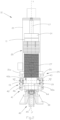
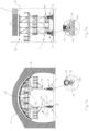
- the number 1 indicates as a whole the equipment according to the present invention, which comprises two supports 10 on which a frame 50 is mounted.
- the equipment can be used for supporting and moving a support structure 100, on top of which the formworks 110, adapted to receive the concrete casting to produce the internal lining of the tunnel, are carried ( Figs. 5-7 ).
- the frame 50 comprises one or more elements 51, for example beams, poles or the like, rigidly joined to one another, which, as a whole, connect the two supports 10 and keep them spaced from and parallel to each other.
- the frame is typically made of steel or other metals with suitable mechanical strength.
- the shape of the frame 50 represented in the figures is merely an example and that any other structural configuration suitable to support the weight of the structure 100 and the loads of the casting transferred to formworks 110 can be adopted.
- Each of the supports 10 comprises a body 11, substantially cylindrical in shape, slidably housed in a guide element 20 fixed rigidly to the frame 50.
- Said guide element 20 comprises a cylindrical tube 21 open at the lower end.
- a first chamber 12 and a second chamber 13 are produced in the body 11.
- the chambers 12, 13 are cylindrical cavities that flow out at the respective ends of the body.
- Two covers 14, 15 close the first chamber 12 and the second chamber 13, respectively.
- a first piston 16 connected to a first rod 17 mounted sliding in an opening 14a of the cover 14.
- a second piston 18 connected to a second rod 19 mounted sliding in an opening 15a of the cover 15.
- the free end of the first rod 17, which extends upward from the body 11, is fixed to the upper side of the guide element 20 and therefore it is also integral with the frame 50.
- the free end of the second rod 19, which extends downward from said body 10, is connected to a supporting element 30.
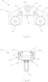
- the support is further provided with rolling means 40 connected to the lower end of the body 10, more precisely to the cover 15 that closes the second chamber 13.
- the rolling means 40 comprise a bracket 41 that includes a first portion 42 hinged on the cover 15 by means of a pin 43 so as to be able to swivel about a substantially horizontal axis X2.
- Said first portion 42 of the bracket 41 supports a second portion 44 mounted on the first portion 42 sliding along a direction parallel to the axis X2.
- At least one pair of wheels 45, aligned along the direction of translation X1 of the equipment along the tunnel, are mounted on the second portion 44.
- the first portion 42 comprises a pair of plates 42a positioned between which are one or more sliding guides 46 connected to the second portion 44.
- said sliding guides 46 are associated, or are integrated, with respective hydraulic, electric or similar actuators, which allow automatic adjustment of the position of the structure 100 with respect to guides or tracks on the ground.
- the first portion 42 and the second portion 44 of the rolling means 40 are shaped so as to have a central housing 47 communicating with the lower end of the body 11, through which the second rod 19 of the second piston 18 can extend and which, in the completely retracted position of the second piston 18, allows the supporting element 30 to remain raised with respect to the bearing plane of the wheels 45.
- the supporting element 30 is preferably in the shape of an arch or a "saddle" so that, when it is resting on the ground, it can remain substantially aligned with the tracks or the guides on which the wheels 45 run.
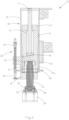
- the free end of the second rod 19 and the supporting element 30 are connected by a centering element 32 which comprises a female seat 33, fixed on the upper part of the supporting element 30, adapted to accommodate a male terminal 34, fixed to the end of the second rod 19.
- the female seat 33 has a partially conical or partially spherical shape and the male terminal 34 has a partially conical or partially spherical shape complementary to the shape of the female seat 33.
- the centering element 32 thus structured allows limited deviations and/or rotations between the second rod 19 and the supporting element 30. In this way the second rod 19, and the support 10 as a whole, can maintain a substantially vertical position regardless of the orientation of the supporting element 30 in the section of ground on which it rests. Moreover, thanks to the centering element 32, lateral or bending forces on the second rod, which could occur due to the arrangement of the supporting element 30 on the ground, are prevented or limited.
- a mechanical locking device 25 comprising a threaded ring nut 26, which can be screwed onto a respective threaded portion 27 produced on a lower end section of the body 11, is provided at the lower end 11a of the body 11.
- Said ring nut 26 is adapted to abut against an abutment area at the lower end 21a of the tube 21 of the guide element 20.
- a sensor is arranged on said tube 21, adapted to detect the contact or proximity of the ring nut 26 with the abutment area of the guide element 20.
- Said sensor is preferably a proximity sensor.
- the position and movement of the first piston 16 are measured preferably by means of a linear transducer 22 comprising two mutually sliding parts 23, 24, respectively fixed to the lower cover 15 and tube 21 of the guide element 20.
- This transducer thus detects the movement of the body 11 with respect to the frame 50, i.e., when the rolling means 40 are resting on the ground, the vertical movement of the frame 50 with respect to the ground.
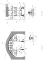
- Figs. 5a, 5b a 7a, 7b illustrate a structure 100 for moving formworks 110 provided with the equipment 1 according to the present invention.
- the structure 100 is represented in different steps during its use in a tunnel G.
- Figs. 5a, 5b the structure 100 and the related formworks 110 are in forming position; the structure is thus in raised position so that the outer surface of the formworks 110 is substantially coincident with the internal surface of the lining R of the tunnel G.
- the casting step has already been carried out and the lining section R has already been formed.
- the first pistons 16 are extended so that the body 11 protrudes at least partly beyond the lower end 21a of the tube 21 of the guide element 20. Moreover, the end 21a of the tube 21 is abutting against the threaded ring nut 26 so that the load is transferred from the frame 50 to the body 11, unloading the first pistons 16.
- Figs. 6a, 6b illustrate the structure 100 in a first stripping step.
- the second pistons 18 are retracted, together with the second rods 19 and with the supporting elements 30, lowering the whole structure 100 by a few millimeters and bringing the wheels 45 into contact with the tracks 120.
- the ring nut 26 is rotated on the thread of the body 11 and is detached from the lower end 21a of the tube 21.
- a second step of complete stripping illustrated in Figs. 7a, 7b , the first pistons 16 are retracted lowering the whole structure 100 by a few tens of centimeters. In this position the structure 100 can be moved along the tracks 120 and be repositioned to produce a new section of the lining R of the tunnel G.
- the forming steps of the structure from the completely lowered position are the opposite of the stripping steps described above.
- the first pistons 16 extend to their maximum stroke or to the predetermined extension position, then the ring nut 16 is taken to abut against the lower end 21a of the tube 21 and, finally, the second pistons 18 extend until the supporting elements 30 are brought into contact with the ground and, continuing their extension, the formworks 110 are taken to the final position, their outer surfaces coincide with the ideal internal surface of the lining of the tunnel which is subsequently cast.
Landscapes
- Engineering & Computer Science (AREA)
- Architecture (AREA)
- Structural Engineering (AREA)
- Mining & Mineral Resources (AREA)
- Civil Engineering (AREA)
- Life Sciences & Earth Sciences (AREA)
- General Life Sciences & Earth Sciences (AREA)
- Geochemistry & Mineralogy (AREA)
- Geology (AREA)
- Lining And Supports For Tunnels (AREA)
Claims (10)
- Vorrichtung (1) zum Abstützen und Bewegen von Schalungen (110), die für den Bau von Tunneln bestimmt sind, wobei besagte Vorrichtung Folgendes umfasst:- mindestens ein Paar Stützen (10), die mit Rollmitteln (40) versehen sind; und- einen Rahmen (50), der auf den besagten Stützen (10) angebracht ist, geeignet, um eine Struktur (100) zu stützen, auf der eine oder mehrere Schalungen (110) installiert sind;wobei jede Stütze (10) einen Körper (11) umfasst, der eine erste Kammer (12) einschließt, in der ein erster Kolben (16) gleitend untergebracht ist, der mit einer ersten, mit dem Rahmen (50) verbundenen Stange (17) ein Ganzes bildet;dadurch gekennzeichnet, dass der besagte Körper (10) ferner Folgendes umfasst:- eine zweite Kammer (13), in der ein zweiter Kolben (18) gleitend untergebracht ist, der mit einer zweiten Stange (19) ein Ganzes bildet; und- ein Stützelement (30), das mit dem Ende der zweiten Stange (19) verbunden ist;wobei die erste Kammer (12) und die zweite Kammer (13) mit einer unter Druck stehenden Hydraulikflüssigkeit versorgt werden können, um die Bewegung der jeweiligen Kolben (17, 19) entlang einer im Wesentlichen vertikalen Achse (Y) zu steuern,wobei der erste Kolben (16) und der zweite Kolben (18) koaxial sind und die jeweiligen Stangen sich vom Körper (11) in entgegengesetzte Richtungen erstrecken,wobei der zweite Kolben (18) zwischen einer eingezogenen Position, in der die Rollmittel (40) der Stütze (10) in Kontakt mit dem Boden sind und das Stützelement (30) angehoben ist, und einer ausgefahrenen Position, in der die besagten Rollmittel (40) angehoben sind und das Stützelement (30) in Kontakt mit dem Boden ist, beweglich ist.
- Die Vorrichtung gemäß Anspruch 1, wobei der erste Kolben (16) mit einer mechanischen Sperrvorrichtung (25) verbunden ist.
- Die Vorrichtung gemäß einem jeden der vorhergehenden Ansprüche, wobei der Körper (11) der Stütze (10) gleitend in einem Führungselement (20) montiert ist, das mit dem Rahmen (50) ein Ganzes bildet.
- Die Vorrichtung gemäß den Ansprüchen 2 und 3, wobei die Sperrvorrichtung (25) eine Gewinderingmutter (26) umfasst, die auf einen Gewindeabschnitt (27) des Körpers (11) aufgeschraubt werden kann, geeignet, um an einem Anschlagbereich (21a) des Führungselements (20) anzuliegen.
- Die Vorrichtung gemäß Anspruch 4, wobei die Sperrvorrichtung (25) einen Sensor umfasst, geeignet, um den Kontakt oder die Nähe der Ringmutter (26) mit dem Anschlagbereich (21a) des Führungselements (20) zu erfassen.
- Die Vorrichtung gemäß einem jeden der vorhergehenden Ansprüche, wobei ein Zentrierelement (32) zwischen der Stange (19) des zweiten Kolbens (18) und dem Stützelement (30) eingefügt ist.
- Die Vorrichtung gemäß einem jeden der vorhergehenden Ansprüche, umfassend einen Sensor, geeignet, um die Bewegung des zweiten Kolbens (18) in der zweiten Kammer (13) zu erfassen, wobei der besagte Sensor im Inneren dieser Kammer oder der Stange (19) des Kolbens (18) untergebracht ist.
- Die Vorrichtung gemäß einem jeden der vorhergehenden Ansprüche, umfassend einen Hydraulikkreislauf zur Versorgung der ersten Kammer (12) und der zweiten Kammer (13) mit einer Hydraulikflüssigkeit und eine Steuereinheit, geeignet, um den besagten Hydraulikkreislaufs zu steuern.
- Die Vorrichtung gemäß Anspruch 8, umfassend Lastsensoren, geeignet, um die Last zu erfassen, die während des Gießschritts auf der Stütze (10) lastet, wobei die Steuereinheit konfiguriert ist, um die von den Lastsensoren gemessenen Daten zu empfangen, den Hydraulikkreislauf zu steuern und gegebenenfalls einen oder mehrere der zweiten Kolben (18) zu betätigen, um ein Absinken des Bodens unter den Stützelementen (30) oder übermäßige Verformungen der Schalungen (110) oder der Struktur (100) auszugleichen.
- Die Vorrichtung gemäß Anspruch 8 oder 9, umfassend weitere Sensoren, geeignet, die Position und/oder Orientierung der Schalungen (110) zu erfassen, wobei die Steuereinheit konfiguriert ist, um die von den vorgenannten Sensoren gemessenen Daten zu empfangen und den Hydraulikkreis zu steuern, um die ersten Kolben (16), die zweiten Kolben (18) oder beide in einer koordinierten Weise zu betätigen, wodurch die Struktur (100) und die Schalungen (110) automatisch zumindest von der Transportposition in Richtung der Formposition bewegt werden.
Applications Claiming Priority (1)
| Application Number | Priority Date | Filing Date | Title |
|---|---|---|---|
| IT102021000025274A IT202100025274A1 (it) | 2021-10-01 | 2021-10-01 | Attrezzatura per il supporto e la movimentazione di casseforme per la realizzazione di gallerie |
Publications (3)
| Publication Number | Publication Date |
|---|---|
| EP4159975A1 EP4159975A1 (de) | 2023-04-05 |
| EP4159975C0 EP4159975C0 (de) | 2024-11-06 |
| EP4159975B1 true EP4159975B1 (de) | 2024-11-06 |
Family
ID=79019178
Family Applications (1)
| Application Number | Title | Priority Date | Filing Date |
|---|---|---|---|
| EP22199018.7A Active EP4159975B1 (de) | 2021-10-01 | 2022-09-30 | Ausrüstung zum stützen und bewegen von schalungen für den bau von tunneln |
Country Status (2)
| Country | Link |
|---|---|
| EP (1) | EP4159975B1 (de) |
| IT (1) | IT202100025274A1 (de) |
Families Citing this family (2)
| Publication number | Priority date | Publication date | Assignee | Title |
|---|---|---|---|---|
| IT202300002424A1 (it) * | 2023-02-13 | 2024-08-13 | Sointek S R L | Attrezzatura per il supporto e la movimentazione di casseforme per la realizzazione di gallerie |
| CN118774134B (zh) * | 2024-09-12 | 2024-12-10 | 安徽建工三建集团有限公司 | 一种用于桩基础工程施工的混凝土浇筑装置 |
Family Cites Families (12)
| Publication number | Priority date | Publication date | Assignee | Title |
|---|---|---|---|---|
| CA757386A (en) * | 1967-04-25 | Pullman Incorporated | Adjustable cushioning arrangement for railroad cars | |
| ATE318991T1 (de) | 1999-10-28 | 2006-03-15 | Zueblin Ag | Verfahren zum verschalen von wandungen eines tunnels und schalung zur durchführung des verfahrens |
| IT1320275B1 (it) | 2000-03-24 | 2003-11-26 | Mecsider S P A | Carro porta-forma a dimensioni regolabili per gallerie. |
| DE102004060753B4 (de) | 2004-12-15 | 2006-11-02 | Muhr Und Bender Kg | Halteelement für eine Federbandschelle |
| DE102004060653B4 (de) | 2004-12-16 | 2007-06-21 | Doka Industrie Gmbh | Schalungsanordnung und Verfahren zum Aufbauen einer Schalungsanordnung |
| FR2895441A1 (fr) * | 2005-12-27 | 2007-06-29 | Robert Parra | Dispositif et procede de coffrage a absorption de poussee, pour tunnel |
| CN102536261B (zh) * | 2012-01-14 | 2014-06-18 | 湖南五新重型装备有限公司 | 一种伸缩式紧急避车带隧道衬砌台车 |
| DE102013104844A1 (de) | 2013-05-10 | 2014-11-13 | Peri Gmbh | Schalungssegment sowie Schalungssystem mit mehreren solchen Schalungssegmenten |
| CN104500102A (zh) * | 2014-12-26 | 2015-04-08 | 山东铁鹰建设工程有限公司 | 一种可伸缩式隧道衬砌台车及该种台车的快速移动方法 |
| ES1144986Y (es) | 2015-09-30 | 2016-04-11 | Amorim Obras Publicas S L | Carro de encofrado auto-portante para el revestimiento de tuneles |
| CN106050271B (zh) * | 2016-08-23 | 2018-03-02 | 中铁十九局集团第七工程有限公司 | 一种隧道用水沟模架装置及其施工方法 |
| DE102016220046A1 (de) | 2016-10-14 | 2018-04-19 | Peri Gmbh | Tragradbaugruppe |
-
2021
- 2021-10-01 IT IT102021000025274A patent/IT202100025274A1/it unknown
-
2022
- 2022-09-30 EP EP22199018.7A patent/EP4159975B1/de active Active
Also Published As
| Publication number | Publication date |
|---|---|
| EP4159975A1 (de) | 2023-04-05 |
| EP4159975C0 (de) | 2024-11-06 |
| IT202100025274A1 (it) | 2023-04-01 |
Similar Documents
| Publication | Publication Date | Title |
|---|---|---|
| EP4159975B1 (de) | Ausrüstung zum stützen und bewegen von schalungen für den bau von tunneln | |
| CN113006829B (zh) | 用于隧道的移动式可调反力临时台架支护系统及支护方法 | |
| EP2231500B1 (de) | Mobile hebeanordnung | |
| US4754713A (en) | Movable platform with adjustable legs | |
| JP4378440B2 (ja) | 橋梁架設用回転装置 | |
| CN107063896B (zh) | 一种可调节压剪综合试验系统技术平台 | |
| WO2023056721A1 (zh) | 高速铁路桥梁支座转角超限病害整治施工工法 | |
| CN111827131A (zh) | 一种模块车架设钢箱梁精确定位施工方法 | |
| CN115382919A (zh) | 一种大型轧机机旁下沉组装主体推移的安装方法 | |
| CN105002919A (zh) | 一种使预制承台与多根固定钢管桩相互定位的系统及其定位工艺 | |
| CN115488154B (zh) | 一种大型宽厚板轧机离线下沉组装整体滑移的安装方法 | |
| LU502085B1 (en) | Intelligent bridge synchronous jacking system and method for high-speed railway | |
| EP1880974A1 (de) | Materialhandhabungsvorrichtung | |
| EP4665951A1 (de) | Vorrichtung zum stützen und bewegen von schalungen für bautunnel | |
| US5562400A (en) | Self-propelled lifting apparatus | |
| CN114720168A (zh) | 一种隧道工程支护结构变形与控制模拟试验系统 | |
| CN221627697U (zh) | 一种装配式建筑定位校准装置 | |
| CN119145631A (zh) | 利用筒体模架系统现浇筒体结构的施工方法 | |
| CN208380117U (zh) | 悬挑钢梁的全自动矫正装置 | |
| CN207727443U (zh) | 一种连续梁顶推及转体装置及系统 | |
| US11851309B2 (en) | Shovel lifting system and method | |
| CN116348408B (zh) | 一种智能吊装机器人 | |
| CN206804451U (zh) | 一种可调节压剪综合试验系统技术平台 | |
| CN107083764A (zh) | 闸门底轴双向小行程调整安装装置 | |
| CN223688804U (zh) | 一种移动式桥梁梁体临时支撑装置 |
Legal Events
| Date | Code | Title | Description |
|---|---|---|---|
| PUAI | Public reference made under article 153(3) epc to a published international application that has entered the european phase |
Free format text: ORIGINAL CODE: 0009012 |
|
| STAA | Information on the status of an ep patent application or granted ep patent |
Free format text: STATUS: THE APPLICATION HAS BEEN PUBLISHED |
|
| AK | Designated contracting states |
Kind code of ref document: A1 Designated state(s): AL AT BE BG CH CY CZ DE DK EE ES FI FR GB GR HR HU IE IS IT LI LT LU LV MC MK MT NL NO PL PT RO RS SE SI SK SM TR |
|
| STAA | Information on the status of an ep patent application or granted ep patent |
Free format text: STATUS: REQUEST FOR EXAMINATION WAS MADE |
|
| RBV | Designated contracting states (corrected) |
Designated state(s): AL AT BE BG CH CY CZ DE DK EE ES FI FR GB GR HR HU IE IS IT LI LT LU LV MC MK MT NL NO PL PT RO RS SE SI SK SM TR |
|
| 17P | Request for examination filed |
Effective date: 20231123 |
|
| GRAP | Despatch of communication of intention to grant a patent |
Free format text: ORIGINAL CODE: EPIDOSNIGR1 |
|
| STAA | Information on the status of an ep patent application or granted ep patent |
Free format text: STATUS: GRANT OF PATENT IS INTENDED |
|
| INTG | Intention to grant announced |
Effective date: 20240424 |
|
| GRAS | Grant fee paid |
Free format text: ORIGINAL CODE: EPIDOSNIGR3 |
|
| GRAA | (expected) grant |
Free format text: ORIGINAL CODE: 0009210 |
|
| STAA | Information on the status of an ep patent application or granted ep patent |
Free format text: STATUS: THE PATENT HAS BEEN GRANTED |
|
| AK | Designated contracting states |
Kind code of ref document: B1 Designated state(s): AL AT BE BG CH CY CZ DE DK EE ES FI FR GB GR HR HU IE IS IT LI LT LU LV MC MK MT NL NO PL PT RO RS SE SI SK SM TR |
|
| REG | Reference to a national code |
Ref country code: GB Ref legal event code: FG4D |
|
| REG | Reference to a national code |
Ref country code: CH Ref legal event code: EP |
|
| REG | Reference to a national code |
Ref country code: IE Ref legal event code: FG4D |
|
| REG | Reference to a national code |
Ref country code: DE Ref legal event code: R096 Ref document number: 602022007451 Country of ref document: DE |
|
| U01 | Request for unitary effect filed |
Effective date: 20241205 |
|
| U07 | Unitary effect registered |
Designated state(s): AT BE BG DE DK EE FI FR IT LT LU LV MT NL PT RO SE SI Effective date: 20241213 |
|
| PG25 | Lapsed in a contracting state [announced via postgrant information from national office to epo] |
Ref country code: IS Free format text: LAPSE BECAUSE OF FAILURE TO SUBMIT A TRANSLATION OF THE DESCRIPTION OR TO PAY THE FEE WITHIN THE PRESCRIBED TIME-LIMIT Effective date: 20250306 Ref country code: HR Free format text: LAPSE BECAUSE OF FAILURE TO SUBMIT A TRANSLATION OF THE DESCRIPTION OR TO PAY THE FEE WITHIN THE PRESCRIBED TIME-LIMIT Effective date: 20241106 |
|
| PG25 | Lapsed in a contracting state [announced via postgrant information from national office to epo] |
Ref country code: ES Free format text: LAPSE BECAUSE OF FAILURE TO SUBMIT A TRANSLATION OF THE DESCRIPTION OR TO PAY THE FEE WITHIN THE PRESCRIBED TIME-LIMIT Effective date: 20241106 |
|
| PG25 | Lapsed in a contracting state [announced via postgrant information from national office to epo] |
Ref country code: NO Free format text: LAPSE BECAUSE OF FAILURE TO SUBMIT A TRANSLATION OF THE DESCRIPTION OR TO PAY THE FEE WITHIN THE PRESCRIBED TIME-LIMIT Effective date: 20250206 |
|
| PG25 | Lapsed in a contracting state [announced via postgrant information from national office to epo] |
Ref country code: GR Free format text: LAPSE BECAUSE OF FAILURE TO SUBMIT A TRANSLATION OF THE DESCRIPTION OR TO PAY THE FEE WITHIN THE PRESCRIBED TIME-LIMIT Effective date: 20250207 |
|
| PG25 | Lapsed in a contracting state [announced via postgrant information from national office to epo] |
Ref country code: PL Free format text: LAPSE BECAUSE OF FAILURE TO SUBMIT A TRANSLATION OF THE DESCRIPTION OR TO PAY THE FEE WITHIN THE PRESCRIBED TIME-LIMIT Effective date: 20241106 |
|
| PG25 | Lapsed in a contracting state [announced via postgrant information from national office to epo] |
Ref country code: RS Free format text: LAPSE BECAUSE OF FAILURE TO SUBMIT A TRANSLATION OF THE DESCRIPTION OR TO PAY THE FEE WITHIN THE PRESCRIBED TIME-LIMIT Effective date: 20250206 |
|
| PG25 | Lapsed in a contracting state [announced via postgrant information from national office to epo] |
Ref country code: SM Free format text: LAPSE BECAUSE OF FAILURE TO SUBMIT A TRANSLATION OF THE DESCRIPTION OR TO PAY THE FEE WITHIN THE PRESCRIBED TIME-LIMIT Effective date: 20241106 |
|
| PG25 | Lapsed in a contracting state [announced via postgrant information from national office to epo] |
Ref country code: SK Free format text: LAPSE BECAUSE OF FAILURE TO SUBMIT A TRANSLATION OF THE DESCRIPTION OR TO PAY THE FEE WITHIN THE PRESCRIBED TIME-LIMIT Effective date: 20241106 |
|
| PG25 | Lapsed in a contracting state [announced via postgrant information from national office to epo] |
Ref country code: CZ Free format text: LAPSE BECAUSE OF FAILURE TO SUBMIT A TRANSLATION OF THE DESCRIPTION OR TO PAY THE FEE WITHIN THE PRESCRIBED TIME-LIMIT Effective date: 20241106 |
|
| PLBE | No opposition filed within time limit |
Free format text: ORIGINAL CODE: 0009261 |
|
| STAA | Information on the status of an ep patent application or granted ep patent |
Free format text: STATUS: NO OPPOSITION FILED WITHIN TIME LIMIT |
|
| 26N | No opposition filed |
Effective date: 20250807 |
|
| U20 | Renewal fee for the european patent with unitary effect paid |
Year of fee payment: 4 Effective date: 20250930 |