EP4159952B1 - Levelling spacing device to facilitate installations of tiles - Google Patents
Levelling spacing device to facilitate installations of tiles Download PDFInfo
- Publication number
- EP4159952B1 EP4159952B1 EP22197958.6A EP22197958A EP4159952B1 EP 4159952 B1 EP4159952 B1 EP 4159952B1 EP 22197958 A EP22197958 A EP 22197958A EP 4159952 B1 EP4159952 B1 EP 4159952B1
- Authority
- EP
- European Patent Office
- Prior art keywords
- flat element
- base
- spacing
- flat
- leveling
- Prior art date
- Legal status (The legal status is an assumption and is not a legal conclusion. Google has not performed a legal analysis and makes no representation as to the accuracy of the status listed.)
- Active
Links
- 238000009434 installation Methods 0.000 title description 27
- 239000000853 adhesive Substances 0.000 description 9
- 230000001070 adhesive effect Effects 0.000 description 9
- 239000000463 material Substances 0.000 description 7
- 238000004519 manufacturing process Methods 0.000 description 5
- 230000000295 complement effect Effects 0.000 description 2
- 230000008878 coupling Effects 0.000 description 2
- 238000010168 coupling process Methods 0.000 description 2
- 238000005859 coupling reaction Methods 0.000 description 2
- 230000000694 effects Effects 0.000 description 2
- 230000007613 environmental effect Effects 0.000 description 2
- 230000005226 mechanical processes and functions Effects 0.000 description 2
- 229920000642 polymer Polymers 0.000 description 2
- 230000015572 biosynthetic process Effects 0.000 description 1
- 230000001419 dependent effect Effects 0.000 description 1
- 238000003912 environmental pollution Methods 0.000 description 1
- 230000002427 irreversible effect Effects 0.000 description 1
- 238000004513 sizing Methods 0.000 description 1
- 239000002699 waste material Substances 0.000 description 1
Images


Classifications
-
- E—FIXED CONSTRUCTIONS
- E04—BUILDING
- E04F—FINISHING WORK ON BUILDINGS, e.g. STAIRS, FLOORS
- E04F21/00—Implements for finishing work on buildings
- E04F21/0092—Separate provisional spacers used between adjacent floor or wall tiles
-
- E—FIXED CONSTRUCTIONS
- E04—BUILDING
- E04F—FINISHING WORK ON BUILDINGS, e.g. STAIRS, FLOORS
- E04F15/00—Flooring
- E04F15/02—Flooring or floor layers composed of a number of similar elements
- E04F15/02005—Construction of joints, e.g. dividing strips
- E04F15/02022—Construction of joints, e.g. dividing strips with means for aligning the outer surfaces of the flooring elements
-
- E—FIXED CONSTRUCTIONS
- E04—BUILDING
- E04F—FINISHING WORK ON BUILDINGS, e.g. STAIRS, FLOORS
- E04F21/00—Implements for finishing work on buildings
- E04F21/18—Implements for finishing work on buildings for setting wall or ceiling slabs or plates
- E04F21/1838—Implements for finishing work on buildings for setting wall or ceiling slabs or plates for setting a plurality of similar elements
- E04F21/1877—Leveling devices
Definitions
- the present invention relates to improvements to leveling spacing devices for facilitating the installation of flat covering elements for horizontal surfaces (floors and ceilings) and vertical surfaces (walls), such as tiles, covering panels and the like.
- leveling spacing devices which are inserted below two, three of four adjacent tiles, is well known.
- the leveling spacing devices comprise, in general, a base adapted to be arranged between the installation surface and the back surface of the tiles.
- a flat element extends from the base, having a thickness equal to the width of the joint to be formed between adjacent tiles.
- the width of the joint is defined by the thickness of the flat element.
- the leveling spacing devices further comprise, or are associated with, a pressing element constrained to the flat element or to an engaging member integral with the flat element.
- the function of the pressing elements is to push the underlying tiles against the installation surface so that the tiles are installed coplanar.
- the pressing elements can be reusable, i.e., used several times, whilst the base and the flat element are for disposable use. Therefore, a certain number of pressing elements can be used several times to apply a high number of bases and corresponding flat elements.
- the base is put under two or more tiles, or other covering elements, so that the flat element, or the engaging member integral therewith, projects from the joint between adjacent tiles, so as to constrain the pressing element to the flat element.
- the pressing element is ada to rest on the two or more adjacent tiles, under which the base of the leveling spacing device is arranged.
- the pressing element and the engaging member are configured to move the pressing element towards the base, generating a push on the visible surfaces of the tiles, on which the pressing element rests. Through the generated push, the adjacent tiles are forced to be arranged coplanar with one another.
- the pressing elements are removed and the flat element is severed from the base. Then, the joints are grouted.
- the base remains in the space between the back surfaces of the tiles and the installation surface, whilst the flat element, or part thereof, is removed and thrown away.
- the pressing elements are recovered and used again for installing further tiles.
- the pressing element is shaped like a wedge that is inserted in a slot formed in the flat element, or between the flat element and the base.
- US2020/0080323 and WO2008/118418 disclose examples of leveling spacing devices of this kind. These devices are not very practical, as a strong effort is required from the operator to insert the wedges. Moreover, these known devices not always ensure coplanarity of tiles, above all in the case of three of four tiles converging on the area where the leveling spacing device is applied, because the surface of the wedge pressing the tiles is very small.
- the pressing element is shaped like a knob or a dome and is configured to be screwed on a threaded stem integral with the flat element, or it has a toothed slot, where the flat element is inserted, having a portion with a toothing complementary to the toothing of the slot.
- US2020/0080323 , WO2020245711 , EP2549030 disclose leveling spacing devices of this kind.
- the leveling spacing devices are single-use devices, except the pressing element, which can be used several times. A part of the leveling spacing device remains inside the covering, between the tiles and the installation surface. The other part of the leveling spacing device, including the flat element, is thrown away after having severed the flat element from the base.
- the dimension (width) of the joints between tiles in a vertical or horizontal covering may vary significantly, according to the desired aesthetic effect.
- the covering elements are installed with very small joints, for instance 1 mm-large joints, in other cases the opposite aesthetic effect is required and the elements are installed with 2 mm-large, or even larger, joints. This requires the use of leveling spacing devices with very thick flat elements.
- the width of the joint increases, the overall dimension of the flat elements increases, as well as the quantity of polymeric material used that, sooner or later, is in large part dispersed in the environment.
- the quantity of polymeric material forming the flat element cannot be reduced by simply reducing the width of the flat element, because a too small flat element has not adequate tensile strength during the leveling step and does not constitute an adequate rest for the tile edges, with a consequent risk of non-parallelism of adjacent tiles and of formation of joints of non-consistent width. From the viewpoint of both the costs and the environmental impact, it would be therefore advantageous to provide a leveling spacing device that at least partially overcomes the drawbacks of the prior art devices, allowing also to reduce the quantity of plastic required for the production, especially for the production of the single-use part of the device.
- a device according to the preamble of claim 1 is disclosed in US 2016/090746 A1 .
- a leveling spacing device is defined in claim 1.
- the dependent claims relate to preferred additional features of the device.
- the device comprises: a base having a lower surface and an upper surface; and a flat element, made in a single piece with the base, extending from the upper surface of the base and having a first plane face and a second plane face parallel to each other and approximately orthogonal to the upper surface of the base.
- the flat element is adapted to be inserted in the joint between two adjacent tiles, and the base is adapted to be arranged between the installation surface and two or more adjacent tiles, inside a layer of adhesive applied between the installation surface and the tiles.
- spacing tabs project from the upper surface of the base, which are coplanar with the flat element and spaced therefrom.
- the spacing tabs being co-planar with the flat element, are adapted, in use, to project in a j oint between adjacent tiles.
- "Coplanar with the flat element” means that the spacing tabs and the flat element have a common lying plane.
- the lying plane of the flat element and the spacing tabs is the median plane parallel to the faces of the flat element and of the spacing tabs, and equidistant therefrom.
- both the flat element and the spacing tabs are co-planar, in use, both the flat element and the spacing tabs extend in a joint between adjacent tiles.
- the flat element provides a connection to a pressing element to level the tiles, while the spacing tabs maintain the tiles at the correct mutual distance, such that a joint of the desired and constant width is obtained.
- the term "tiles" will be used for the covering of both horizontal (floors and ceilings) and vertical (walls) surfaces.
- the leveling spacing device of the invention can be used for any flat covering elements, especially for large covering slabs.
- the leveling spacing device is particularly useful for installing large flat covering slabs. Therefore, the term “tile” shall not be understood as limiting the possible uses of the leveling spacing device disclosed herein.
- the function of the spacing tabs is to keep a constant distance between adjacent tiles, under which the base has been put, to ensure that the width of the joints between the tiles is consistent.
- the thickness of the flat element shall not be necessarily equal to the width of the joint; on the contrary, it can be significantly thinner. This allows to significantly reduce the quantity of polymeric material necessary for producing the leveling spacing device.
- the flat element shall have a height at least equal to the maximum thickness of the tiles and a width sufficient to ensure tensile strength to resist the traction by the pressing element. It is therefore not possible to freely set these two dimensions (height and width) of the flat element to reduce the quantity of plastic used.
- the thickness of the flat element can be significantly smaller than that of the prior art leveling spacing devices, as the correct distance between adjacent tiles (i.e., the width of the joint between adjacent tiles) is ensured by the spacing tabs and not by the flat element.
- the height of the spacing tabs can be significantly smaller than the thickness of the tiles. Spacing tabs of small height can be used also for tiles of large thickness. Therefore, the quantity of plastic necessary to produce the spacing tabs can be significantly reduced. Also, the width of the spacing tabs can be small, especially if two spacing tabs are used, spaced from each other and arranged coplanar with the flat element and on opposite side thereof.
- each leveling spacing device there is also the advantage of keeping the spacing tabs embedded in the joint between two tiles, even after having severed and removed the flat element. This is particularly useful when the flat element accidentally breaks under the traction of the pressing element, i.e., before the adhesive has set.
- the prior art devices in case of accidental breakage of the flat element, no element remains between adjacent tiles to ensure the correct mutual position of the tiles, and therefore the constant width of the j oint.
- the device according to the invention solves this problem too, as the spacing tabs are not integral with the flat element and are not removed therewith in case of accidental breakage.
- the leveling spacing device comprises also a pressing element, adapted to be constrained to an engaging member integral with the flat element; the engaging member and the pressing element are configured to move the pressing element and the base towards each other.
- the pressing element can be used several times, in general the number of leveling spacing devices is often higher than the number of pressing elements. In other words, not each leveling spacing device is necessarily equipped with a corresponding unique pressing element.
- Kits can be provided, comprised of leveling spacing devices and spacing tabs of variable thickness, typically from 1 mm to 5 mm, according to the width of the required joint between adjacent tiles.
- the spacing tabs have a thickness equal to, or greater than, the thickness of the flat element.
- the number of spacing tabs coplanar with one another and with the flat element can be variable.
- two spacing tabs are preferably provided, arranged symmetrically relative to the flat element and spaced from the side edges of the flat element, which extend orthogonally relative to the base.
- the term "coplanar" indicates two elements sharing the same median plane, or lying plane, wherein median plane, or lying plane, refers to the geometrical plane crossing the element parallel to, and equidistant from, the main faces thereof.
- the spacing tabs and the flat element are coplanar, which means that the median geometrical plane of the flat element, parallel to, and equidistant from, the two side faces of the flat element, is also the median plane of the spacing tabs, parallel to opposite faces of the spacing tabs destined to touch the adjacent tiles.
- the upper surface of the base of the leveling spacing device is preferably flat, to completely rest on the back surface of the tiles.
- the engaging member, coupled to the flat element, and the pressing element can be mutually coupled in any manner adapted to ensure the leveling pressure exerted by the pressing element on the underlying tiles that are put over the base of the leveling spacing device.
- the coupling between flat element and pressing element is a screw coupling, with an outer thread integral with the flat element, provided for example on a stem that, in use, remains outside the thickness of the tiles, and engages an inner thread provided in a hole of the pressing element.
- the pressing element can be shaped like a knob or a dome, that a user can easily hold so as to rotate and to screw it on the threaded stem.
- the lower surface of the base has a concave shape defining a central cavity, surrounded by a perimeter edge that preferably lies on a plane.
- the average thickness of the base is essentially reduced, with consequent savings in polymeric material.
- the plane edge surrounding the central cavity of the back surface of the base ensures that the base is correctly laid on the installation surface and that the upper surface of the base is perfectly parallel to the installation surface. This, in turn, ensures the parallelism of the tiles relative to the installation surface.
- the leveling spacing device When the leveling spacing device is put in the joint between two adjacent tiles, it is sufficient to have two spacing tabs parallel to the flat element. However, in some situations it is necessary or useful to put the leveling spacing device in the point where four tiles converge, i.e., where two joints form an X-intersection, or in the midpoint of the edge of a tile, where two adjacent tiles converge, i.e., where two joints form a T-intersection.
- leveling spacing devices comprising, in addition to the flat element and the spacing tabs coplanar with the flat element, one or two auxiliary spacing tabs extending orthogonally to the upper surface of the base and extending according to a plane orthogonal to the plane where the flat element lies.
- each auxiliary spacing tab is advantageously integral with the flat element and projects from one of the two opposite faces thereof, instead of being integral with the base.
- the possibility is not excluded, however, to provide the auxiliary spacing tabs as projections extending from the upper surface of the base, analogously to the main spacing tabs, i.e., the spacing tabs parallel to the plane where the flat element lies.
- each auxiliary spacing tab has a thickness equal to, or greater than, the thickness of the flat element, and preferably equal to the thickness of the spacing tabs.
- a leveling spacing device for installing flat covering elements, comprising: a base having a lower surface and an upper surface; and a flat element extending from the upper surface of the base and having a first plane face and a second plane face parallel to each other and approximately orthogonal to the upper surface of the base.
- the lower surface of the base has a concave shape defining a central cavity surrounded by an edge that lies on a plane.
- Figs. 20-21 show two axonometric views of a leveling spacing device.
- Fig. 22 is a view from the bottom according to XXII-XXII of Fig. 18 .
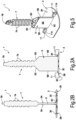
- Figs. 1 to 5 show a first embodiment of the leveling spacing device of the invention.
- the pressing element is not shown, which will be described with reference to Figs. 6 to 10 and can have the same conformation for different embodiments.
- Reference number 1 indicates the whole leveling spacing device. It has a base 3 having two opposite surfaces, referred to, for the sake of practicality, as upper surface 3A and lower surface 3B, respectively. As it will be explained hereunder, in use the lower surface 3B faces the installation surface where the tiles, or other flat covering elements, shall be installed, for instance the surface of a screed, whilst the upper surface 3A faces the tile or flat covering element.
- the base 3 is essentially shaped like a flat sheet.
- the upper surface 3A of the base 3 is preferably flat.
- the lower surface 3B of the base 3 may be concave, as shown in particular in Figs. 2A, 2B and 4 .
- the lower surface 3B has a cross-shaped concavity 3C ( Fig. 4 ) surrounded by a perimeter edge 3D, which preferably has a plane surface, preferably parallel to the upper surface 3A.
- a central concavity 3C of the lower surface 3B of the base 3 allows to reduce the quantity of plastic necessary for producing the leveling spacing device 1.
- the edge 3D surrounding the central concavity 3C and having a plane surface parallel to the upper surface 3A allows to correctly position the leveling spacing device on the installation surface, and gives the base 3 sufficient strength, even when the thickness of the base 3, in the area where the concavity 3C is provided, is very limited.
- a flat element 5 extends from the upper surface 3A of the base 3.
- the flat element 5 has a first plane face and a second plane face parallel to each other and both indicated with reference number 5A, extending approximately orthogonal to the upper surface 3A of the base 3.
- the plane faces 5A are equidistant from a median plane, or lying plane of the flat element 5, indicated with P-P ( Fig. 2 ).
- Reference 5B indicates two side edges connecting the two plane faces 5A.
- the two side edges 5B are rectilinear and parallel to each other, so that the flat element 5 has constant width.
- the reference 5C indicates an edge of the flat element 5, along which the flat element 5 is connected to the upper surface (3A) of the base 3.
- the top of the flat element 5 is connected, along a connection edge 5D, to a threaded stem 7.
- the flat element 5 has an upper portion along the edge 5B, opposite to the edge 5C, of slightly greater thickness forming the area where the flat part of the flat element 5 is connected to the threaded stem 7.
- the reference 7A indicates an outer thread of the threaded stem 7.
- the top of the stem 7 has a flat appendix 7B, coplanar with the flat element 5 or whose median lying plane is parallel to the median lying plane P-P of the flat element 5.
- the flat appendix 7B allows to detect the orientation of the flat element 5 even when this latter is completely contained within the joints defined by the tiles, or other flat covering elements, especially when the leveling spacing device 1 is inserted in an intersection between two joints, in the area where four tiles converge. This is useful to facilitate the removal of the flat element 5 and the stem 7 after the adhesive, through which the tiles are applied to the installation surface, has set.
- the flat element 5 has a very small thickness, compatibly with the mechanical strength required in the tile leveling phase.
- the thickness can be the smaller the greater the width of the flat element 5, i.e., the mutual distance between the edges 5B. This thickness is not bound to the transversal dimension of the joints between tiles, as better described below.
- the leveling spacing device 1 Since the leveling spacing device 1 is used to lay the tiles at the correct mutual distance in order to have joints between adjacent tiles of the desired width, and since the flat element 5 has a small thickness for the reasons outlined above, the leveling spacing device 1 has an independent component physically separated from the flat element 5, to ensure that adjacent tiles are laid at the right mutual distance, i.e., with joints of the desired width.
- the width of the joints can be equal to, or greater, even much greater than, the thickness of the flat element 5.
- the flat element 5 can be 1 mm-thick and the width of the joint can be 2 mm - 5 mm.
- the leveling spacing device 1 has a pair of spacing tabs 11, which project orthogonally from the upper surface 3A of the base 3.
- the spacing tabs 11 have opposite flat faces 11A parallel to each other.
- the lying plane of the spacing tabs 11, i.e., the median plane parallel to the faces 11A and equidistant therefrom, coincides with the lying plane P-P, i.e., the median plane of the flat element 5.
- the thickness of the spacing tabs 11 is slightly greater than the thickness of the flat element 5, but in other embodiments the thickness of the spacing tabs 11 is a multiple of the thickness of the flat element 5.
- the flat element 5 can have a thickness of 1 mm
- the spacing tabs 11 can have thicknesses variable from 1 mm to 5 mm, to provide joints of different widths, based on the user's needs.
- the function of the spacing tabs 11 is to install adjacent tiles at the right distance from one another, the distance being defined by the thickness of the spacing tabs. To this end, it is not necessary that the spacing tabs 11 extend upwards from the base 3 beyond the maximum thickness of the tiles, what is indeed necessary for the flat element 5. Furthermore, the spacing tabs 11 do not have any mechanical function of connection with the stem 7 and therefore the sizing thereof must not satisfy any requirement in terms of tensile strength.
- the spacing tabs 11 can have a width and a height substantially smaller than the width and the height of the flat element 5, and the quantity of plastic material (polymer) required to produce the spacing tabs 11 is thus minimized.
- the leveling spacing device 1 described above is used as illustrated in the operating sequence of Figs. 6 to 10 .
- S indicates a surface on which the tiles, or other flat covering elements, indicated by ER, shall be installed.
- the installation surface S can be the upper surface of a screed M.
- the letter C indicates an adhesive applied to the installation surface S.
- Figs. 6 to 10 illustrates the installation of a tile or other flat covering element ER2 at the side of a covering element ER1, installed in a previous phase.
- a leveling spacing device 1 is firstly inserted arranging a part of the base 3 under the back surface of the first tile ER1, i.e., between the back surface and the installation surface S.
- the leveling spacing device 1 is positioned, relative to the tile ER1, in such a way that the flat element 5, and therefore the spacing tabs 11, are parallel to the edge B1 of the tile ER1.
- the spacing tabs 11 touch, with one of their flat faces 11A, the edge B1 of the tile ER1 ( Fig. 7 ).
- the second tile ER2 is positioned on the installation surface S, with the edge B2 of the tile ER2 arranged parallel to the edge B1 of the tile ER1.
- the tile ER2 is positioned in such a way that the edge B2 thereof touches the flat faces 11A of the spacing tabs 11 opposite the flat faces 11A touching the edge B1 of the tile ER1.
- the second tile ER2 is then pushed against the installation surface S ( Figs. 8 and 9 ) until to adhere thereto thanks to the adhesive C, abutting on the upper surface 3A of the base 3.
- a pressing element 15 is used.
- the pressing element is part of the leveling spacing device 1 during the installation of the tiles, but it is a reusable part thereof, while the elements illustrated in Figs. 1 to 5 are single-use elements.
- the pressing element 15 is generically shaped as a dome or a knob, with a lower plane edge 15A lying on a plane orthogonal to a longitudinal axis of the dome.
- the pressing element 15 further comprises gripping and handling means 15B, which are shaped, in the illustrated example, as a pair of upper appendices, but can have different shapes.
- the pressing element 15 has a cylindrical portion 15C, inside which an inner thread 15D is provided.
- the inner thread 15D is so configured as to screw the pressing element 15 on the threaded stem 7.
- the pressing element 15 is screwed on the stem 7 and brought to abut, with the lower flat edge 15A, on the visible surfaces of the tiles ER1, ER2.
- the operator can screw, with a light effort, the pressing element 15 on the stem 7 so as to press on the underlying tiles ER1, ER2 and to ensure that the visible surfaces of the tiles are coplanar with each other.
- Fig. 9 shows the result of this leveling operation.
- the part of the leveling spacing device 1 projecting from the covering surface can be removed.
- the pressure element 15 is firstly removed by unscrewing it from the stem 7; then, the operator hits the stem 7, thus causing the breakage of the flat element 5 and the detachment thereof from the base 3.
- the base 3 remains, with the spacing tabs 11, under and between the tiles ER1, ER2, while the stem 7 and the flat element 5 are removed (see Fig. 10 ).
- the mutual positioning and spacing of the tiles ER1, ER2 is ensured by the spacing tabs 11 of the leveling spacing device 1, and the flat element 5 can have a thickness substantially smaller than the distance between the edges B1, B2 of the two adjacent tiles ER1, ER2.
- the flat element 5 can be optimally sized for the mechanical function it must perform, without constraints as regards the width of the joint F ( Fig. 10 ) between tiles, thus reducing the waste of material.
- a further advantage of the leveling spacing device 1 of the invention is that it keeps the spacing function even if the flat element 5 breaks while the pressing element 15 is screwed, since the spacing tabs 11 remain in the right position and ensure the correct distance (joint F) between the tiles.
- the thread 7A constitutes a possible engaging member, integral with the flat element 5, adapted to fasten the flat element 5 to the pressing element 15.
- other engaging means can be provided for fastening the pressing element 15 and the flat element 5 together.
- the flat element 5 can have a length greater than that illustrated and approximately equal to the overall length of the component formed by the flat element 5 and the stem 7.
- the flat element 5 may be provided with teeth on one or both faces 5A, at least in the part farthest from the base 3.
- the pressing element 15 may be provided with a slot having a shape complementary to the toothed portion of the flat element 5, in order to couple the pressing element 15 and the flat element 5 in irreversible fashion.
- FIGs. 11 to 14 are views of the leveling spacing device 1 in a second embodiment, particularly adapted for being inserted in the point where three tiles are placed adjacent to one another forming two joints intersecting together in T-fashion.
- Fig. 15 schematically shows a portion of a covering where the leveling spacing device of Figs. 11 to 14 can be used, with tiles arranged according to a staggered pattern; T indicates the area where two joints intersect together.
- the same reference numbers indicate the same or equivalent parts to those described with reference to Figs. 1 to 5 and they will be not described again.
- the leveling spacing device 1 of Figs. 11 to 14 differs from that of Figs. 1 to 5 in that a first auxiliary spacing tab 31 is provided, extending orthogonally to the upper surface 3A of the base 3 and orthogonally to the plane faces 5A of the flat element 5.
- the auxiliary spacing tab 31 is integral with the flat element 5 and projects from a flat face 5A thereof, because this allows a simpler production mold; however, it is also possible that the auxiliary spacing tab 31 is integral with the base 3 and projects from the upper surface 3A thereof.
- the auxiliary spacing tab 31 has advantageously a thickness substantially equal to the thickness of the spacing tabs 11.
- a leveling spacing device it is useful to arrange a leveling spacing device at the point where four tiles converge and where two joints cross in X-fashion.
- a leveling spacing device 1 in a modified embodiment illustrated in Figs. 16, 17 and 18 .
- the same numbers indicate the same or equivalent parts to those of the previous figures, which will be not described again.
- the difference between the leveling spacing device 1 of Figs. 16 to 18 and that of the embodiment of Figs. 11 to 14 is the presence of two auxiliary spacing tabs 31, coplanar with each other and opposite with respect to the median plane, i.e., the lying plane of the flat element 5.
- auxiliary tabs 31 can be made in a single piece with the flat element 5, as illustrated in the attached figures, in order to simplify the mold.
- auxiliary spacing tabs 31 integral with the base 3 and projecting orthogonally from the upper surface 3A thereof.
- a leveling spacing device 1 can be positioned, of the type illustrated in Figs. 16 to 18 , with the spacing tabs 11 inserted in the joint F1 and the auxiliary spacing tabs 31 inserted in the joint F2, or vice versa.
- All the embodiments described above of the leveling spacing device 1 of the invention have the advantage of defining the joints between adjacent tiles by means of spacing tabs 11 and/or auxiliary spacing tabs 31, separate and distinct from the flat element 5, whose residual function is to provide a mechanical connection between the base 3 of the leveling spacing device 1 and the pressing element 15, through which the leveling thrust is exerted on adjacent tiles.
- the use of spacing tabs in addition to, and separate from, the flat element 5 has advantages from many viewpoints, especially the reduction of the quantity of plastic necessary for producing each leveling spacing device 1, with advantages in terms of cost and reduction of environmental pollution.
- This latter advantage is increased by making the base 3 of the leveling spacing device 1 provided with a central concavity 3C, which further reduces the mass of polymer necessary for producing the device.
- a subject of the present disclosure is a leveling spacing device for installing flat tile according to claim 1.
- Such device can comprise a pressing element as described in combination with Figs. 1 to 19 adapted to be constrained to an engaging member integral with the flat element, the engaging member and the pressing element being adapted to move the pressing element and the base towards each other.
- the upper surface of the base can be flat and the edge surrounding the central cavity of the lower surface can be planar and parallel to the upper surface of the base.
Applications Claiming Priority (1)
| Application Number | Priority Date | Filing Date | Title |
|---|---|---|---|
| IT102021000025334A IT202100025334A1 (it) | 2021-10-04 | 2021-10-04 | Dispositivo distanziatore livellante per facilitare la posa in opera di piastrelle e analoghi elementi piani di rivestimento |
Publications (3)
| Publication Number | Publication Date |
|---|---|
| EP4159952A1 EP4159952A1 (en) | 2023-04-05 |
| EP4159952B1 true EP4159952B1 (en) | 2023-10-25 |
| EP4159952C0 EP4159952C0 (en) | 2023-10-25 |
Family
ID=78829576
Family Applications (1)
| Application Number | Title | Priority Date | Filing Date |
|---|---|---|---|
| EP22197958.6A Active EP4159952B1 (en) | 2021-10-04 | 2022-09-27 | Levelling spacing device to facilitate installations of tiles |
Country Status (3)
| Country | Link |
|---|---|
| EP (1) | EP4159952B1 (it) |
| IT (1) | IT202100025334A1 (it) |
| PL (1) | PL4159952T3 (it) |
Citations (2)
| Publication number | Priority date | Publication date | Assignee | Title |
|---|---|---|---|---|
| EP0465394A1 (fr) * | 1990-07-04 | 1992-01-08 | Fulvio Tavoschi | Cale double perfectionnée pour la pose des carreaux d'un carrelage |
| US20160090746A1 (en) * | 2013-06-04 | 2016-03-31 | Raimondi S.P.A. | Levelling spacer device for laying slab products for cladding surfaces |
Family Cites Families (6)
| Publication number | Priority date | Publication date | Assignee | Title |
|---|---|---|---|---|
| GB2459412B (en) | 2007-03-26 | 2011-12-07 | Q E P Co Inc | Device for leveling and aligning tiles and method for leveling and aligning tiles |
| ITPD20110295A1 (it) * | 2011-09-20 | 2013-03-21 | Progress Profiles Spa | Distanziatore livellante per la posa di piastrelle, mattonelle e simili con interposizione di fughe |
| US9487959B2 (en) | 2013-04-09 | 2016-11-08 | Clinton D. Bunch | Device for leveling and aligning tiles and method for leveling and aligning tiles |
| US10577813B2 (en) * | 2018-02-08 | 2020-03-03 | Tti (Macao Commercial Offshore) Limited | Tile leveling device |
| IT201900008349A1 (it) | 2019-06-07 | 2020-12-07 | Raimondi Spa | Dispositivo distanziatore livellante |
| US11105102B2 (en) * | 2019-11-05 | 2021-08-31 | Clinton D. Bunch | Leveling clip and tile leveling device for use of same |
-
2021
- 2021-10-04 IT IT102021000025334A patent/IT202100025334A1/it unknown
-
2022
- 2022-09-27 EP EP22197958.6A patent/EP4159952B1/en active Active
- 2022-09-27 PL PL22197958.6T patent/PL4159952T3/pl unknown
Patent Citations (2)
| Publication number | Priority date | Publication date | Assignee | Title |
|---|---|---|---|---|
| EP0465394A1 (fr) * | 1990-07-04 | 1992-01-08 | Fulvio Tavoschi | Cale double perfectionnée pour la pose des carreaux d'un carrelage |
| US20160090746A1 (en) * | 2013-06-04 | 2016-03-31 | Raimondi S.P.A. | Levelling spacer device for laying slab products for cladding surfaces |
Also Published As
| Publication number | Publication date |
|---|---|
| EP4159952A1 (en) | 2023-04-05 |
| IT202100025334A1 (it) | 2023-04-04 |
| PL4159952T3 (pl) | 2024-03-25 |
| EP4159952C0 (en) | 2023-10-25 |
Similar Documents
| Publication | Publication Date | Title |
|---|---|---|
| EP2573296B1 (en) | Leveling spacer for laying wall tiles, paving tiles and the like with the interposition of gaps | |
| US8800246B2 (en) | Tile levelling device | |
| US9945133B2 (en) | System and method for aligning and leveling tile | |
| EP3695073B1 (en) | Tile spacer | |
| US20040250435A1 (en) | Tile spacer for positioning tiles during installation | |
| CA3044402A1 (en) | Levelling spacer device | |
| US20180100315A1 (en) | Lippage control system with stretchable strap portion | |
| KR20160138449A (ko) | 상호 로킹 가능한 패널의 세트 | |
| EP3421686B1 (en) | Positioning system for covering elements | |
| US20120198789A1 (en) | Tile spacer | |
| EP2762658B1 (en) | Device for installation of tiles | |
| EP3569793A1 (en) | Levelling part for cladding tiles | |
| CA2892352C (en) | Improved wedge system | |
| US10626624B2 (en) | Tile spacer and wedge tool | |
| EP4159952B1 (en) | Levelling spacing device to facilitate installations of tiles | |
| US20190338536A1 (en) | Spacer for laying tiles, bricks and the like with the interposition of gaps | |
| ITMO20110087A1 (it) | Dispositivo ausiliario per la messa in opera di manufatti lastriformi per il rivestimento di pavimenti e/o pareti | |
| US20050247000A1 (en) | Interlocking self-aligning cladding panel for floors, walls, ceilings, or the like | |
| US9663954B1 (en) | Interlocking roof cement paver and method to manufacture | |
| EP3853428B1 (en) | Tile positioning device | |
| KR20190076739A (ko) | 타일 시공용 시트 | |
| TWM542680U (zh) | 磚板 | |
| WO2018190824A1 (en) | Interlocking roof cement paver and method to manufacture | |
| DE202017001746U1 (de) | Flächige Verbundelemente zur Herstellung von Belägen und Bekleidungen | |
| AU2002332961A1 (en) | Tile spacer for positioning tiles during installation |
Legal Events
| Date | Code | Title | Description |
|---|---|---|---|
| STAA | Information on the status of an ep patent application or granted ep patent |
Free format text: STATUS: EXAMINATION IS IN PROGRESS |
|
| PUAI | Public reference made under article 153(3) epc to a published international application that has entered the european phase |
Free format text: ORIGINAL CODE: 0009012 |
|
| 17P | Request for examination filed |
Effective date: 20221102 |
|
| AK | Designated contracting states |
Kind code of ref document: A1 Designated state(s): AL AT BE BG CH CY CZ DE DK EE ES FI FR GB GR HR HU IE IS IT LI LT LU LV MC MK MT NL NO PL PT RO RS SE SI SK SM TR |
|
| REG | Reference to a national code |
Ref country code: DE Ref legal event code: R079 Ref document number: 602022000790 Country of ref document: DE Free format text: PREVIOUS MAIN CLASS: E04F0021000000 Ipc: E04F0015020000 Ref country code: DE Ref legal event code: R079 Free format text: PREVIOUS MAIN CLASS: E04F0021000000 Ipc: E04F0015020000 |
|
| GRAP | Despatch of communication of intention to grant a patent |
Free format text: ORIGINAL CODE: EPIDOSNIGR1 |
|
| STAA | Information on the status of an ep patent application or granted ep patent |
Free format text: STATUS: GRANT OF PATENT IS INTENDED |
|
| RIC1 | Information provided on ipc code assigned before grant |
Ipc: E04F 21/00 20060101ALI20230420BHEP Ipc: E04F 21/18 20060101ALI20230420BHEP Ipc: E04F 15/02 20060101AFI20230420BHEP |
|
| INTG | Intention to grant announced |
Effective date: 20230512 |
|
| GRAS | Grant fee paid |
Free format text: ORIGINAL CODE: EPIDOSNIGR3 |
|
| GRAA | (expected) grant |
Free format text: ORIGINAL CODE: 0009210 |
|
| STAA | Information on the status of an ep patent application or granted ep patent |
Free format text: STATUS: THE PATENT HAS BEEN GRANTED |
|
| AK | Designated contracting states |
Kind code of ref document: B1 Designated state(s): AL AT BE BG CH CY CZ DE DK EE ES FI FR GB GR HR HU IE IS IT LI LT LU LV MC MK MT NL NO PL PT RO RS SE SI SK SM TR |
|
| REG | Reference to a national code |
Ref country code: GB Ref legal event code: FG4D |
|
| REG | Reference to a national code |
Ref country code: CH Ref legal event code: EP |
|
| REG | Reference to a national code |
Ref country code: DE Ref legal event code: R096 Ref document number: 602022000790 Country of ref document: DE |
|
| REG | Reference to a national code |
Ref country code: IE Ref legal event code: FG4D |
|
| U01 | Request for unitary effect filed |
Effective date: 20231031 |
|
| U07 | Unitary effect registered |
Designated state(s): AT BE BG DE DK EE FI FR IT LT LU LV MT NL PT SE SI Effective date: 20231107 |
|
| PG25 | Lapsed in a contracting state [announced via postgrant information from national office to epo] |
Ref country code: GR Free format text: LAPSE BECAUSE OF FAILURE TO SUBMIT A TRANSLATION OF THE DESCRIPTION OR TO PAY THE FEE WITHIN THE PRESCRIBED TIME-LIMIT Effective date: 20240126 |
|
| PG25 | Lapsed in a contracting state [announced via postgrant information from national office to epo] |
Ref country code: IS Free format text: LAPSE BECAUSE OF FAILURE TO SUBMIT A TRANSLATION OF THE DESCRIPTION OR TO PAY THE FEE WITHIN THE PRESCRIBED TIME-LIMIT Effective date: 20240225 |