EP4159926A1 - Verankerungsanordnung - Google Patents
Verankerungsanordnung Download PDFInfo
- Publication number
- EP4159926A1 EP4159926A1 EP21199869.5A EP21199869A EP4159926A1 EP 4159926 A1 EP4159926 A1 EP 4159926A1 EP 21199869 A EP21199869 A EP 21199869A EP 4159926 A1 EP4159926 A1 EP 4159926A1
- Authority
- EP
- European Patent Office
- Prior art keywords
- anchor
- anchor member
- frame
- floating object
- anchoring arrangement
- Prior art date
- Legal status (The legal status is an assumption and is not a legal conclusion. Google has not performed a legal analysis and makes no representation as to the accuracy of the status listed.)
- Withdrawn
Links
Images
Classifications
-
- E—FIXED CONSTRUCTIONS
- E02—HYDRAULIC ENGINEERING; FOUNDATIONS; SOIL SHIFTING
- E02B—HYDRAULIC ENGINEERING
- E02B3/00—Engineering works in connection with control or use of streams, rivers, coasts, or other marine sites; Sealings or joints for engineering works in general
- E02B3/04—Structures or apparatus for, or methods of, protecting banks, coasts, or harbours
- E02B3/06—Moles; Piers; Quays; Quay walls; Groynes; Breakwaters ; Wave dissipating walls; Quay equipment
- E02B3/062—Constructions floating in operational condition, e.g. breakwaters or wave dissipating walls
- E02B3/064—Floating landing-stages
Definitions
- the invention relates to an anchoring arrangement according to the preamble of claim 1.
- Anchoring of floating objects may be costly and time-consuming. Typically, about half of the installation costs of the pier are related to the anchoring.
- the pier may be anchored on vertical piles driven into the bottom of the water body or by means of chains attached to the pier and weights at the bottom of the water body. Both anchoring solutions require a lot of installation work, and the use of auxiliary equipment, such as installation platform and/or pile-driver, may be necessary. Further, piers secured with chains tend to move on the water surface when the water level is low, which may be harmful.
- the object of the present invention is to provide an improved anchoring arrangement for anchoring a floating object to a bottom of water body.
- the object of the invention can be achieved by the anchoring arrangement according to claim 1.
- the anchoring arrangement comprises a first anchor element and a second anchor element configured to be placed on the bottom of water body at a distance from each other, an anchor frame connected to the first anchor element and the second anchor element, a first anchor member having a first end pivotally connectable to the floating object and a second end pivotally connected to the anchor frame, and a second anchor member having a first end pivotally connectable to the floating object and a second end pivotally connected to the anchor frame.
- Vertical distance between the anchor frame and the first ends of the first anchor member and the second anchor member is adjustable.
- the second end of the first anchor member and the second end of the second anchor member are movable/slidable along the anchor frame towards and away from each other.
- the first end of the first anchor member and the first end of the second anchor member are movable towards and away from each other.
- first anchor member and/or the second anchor member are configured to extend and retract in their longitudinal direction.
- the first end of the first anchor member is located horizontally closer to the second end of the second anchor member than the first end of the second anchor member, and the first end of the second anchor member is located horizontally closer to the second end of the first anchor element than the first end of the first anchor element.
- first anchor member and the second anchor member are tilted towards each other so that they intersect each other.
- first end of the first anchor member and the second end of the second anchor member are located on one side of an intersection of the first anchor member and the second anchor member, and the first end of the second anchor member and the second end of the first anchor member are located on the opposite side of the intersection.
- the second end of the first anchor member is pivotally connected to the anchor frame between the second anchor element and the second end of the second anchor member, and the second end of the second anchor member is pivotally connected to the anchor frame between the first anchor element and the second end of the first anchor member.
- the anchor frame comprises at least two parallel connecting bars arranged at a distance from each other, the first ends of the connecting bars being attached to the first anchor element and the seconds ends of the connecting bars being attached to the second anchor element.
- the first anchor member comprises at least two anchor bars arranged at a distance from each other, first ends of the first anchor bars being pivotally connectable to the floating object and the seconds ends of the first anchor bars being pivotally connected to the anchor frame.
- the second anchor member comprises at least two parallel second anchor bars arranged at a distance from each other, first ends of the second anchor bars being pivotally connectable to the floating object and the seconds ends of second the anchor bars being pivotally connected to the anchor frame.
- the anchoring arrangement is provided with a lifting mechanism configured to lift the anchor elements and the anchor frame against the floating object and lower the anchor elements and the anchor frame to the bottom of the water body.
- the anchor frame comprises at least one lower slide along which the second end first anchor member and the second end of the second anchor member are configured to slide toward and away from each other.
- the anchoring arrangement comprises at least one upper slide along which the first end of the first anchor member and the first end of the second anchor member are configured to slide toward and away from each other, the at least one upper slide being connectable to the floating object.
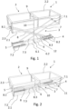
- Figs. 1 and 2 show an anchoring arrangement 3 according to an embodiment of the invention for anchoring a floating object 1 to a bottom of water body.
- the anchoring arrangement 3 is connected to the floating object 1.
- the floating object 1 may be a pier or pier module, as shown in the drawings, that may be used as a mooring and/or a storage platform for boats.
- the pier module 1 may be a part of a pier that comprises a plurality of pier modules 1 connected together.
- the pier module comprises a frame 2 having a lower frame part 2.1 and an upper frame part 2.2.
- the lower and upper frame parts may be rectangular.
- the lower frame part 2.1 and the upper frame part 2.2 are arranged one on top of the other and at a distance from each other in the vertical direction.
- the frame 2 further comprises connecting posts 2.3 that connect the lower frame part 2.1 and the upper frame part 2.2 to each other.
- the connecting posts 2.3 are located at least at the corners of the frame parts 2.1, 2.2.
- the frame 2 comprises at least one float which may be located within the frame 2, for example between the frame parts 2.1, 2.2.
- the pier module may comprise a deck placed above the float (s) . The deck is attached to the frame 2, typically to the upper frame part 2.2.
- the floating object 1, such as the pier module 2 comprises an anchoring arrangement 3 for anchoring the object 1 to the bottom of the water body.
- the anchoring arrangement 3 comprises a first anchor element 4 and a second anchor element 5 configured to be placed on the bottom of the water body at a distance from each other.
- the anchor elements 4,5 may be anchor weights.
- the anchor elements 4, 5 may be made of reinforced concrete or steel.
- the anchor elements 4,5 may comprise friction elements that prevent the sliding of the anchor elements 4,5 along the bottom of the water body.
- the anchoring arrangement 3 further comprises an anchor frame 6 connected to the first anchor element 4 and the second anchor element 5.
- the anchor frame 6 may comprise at least two parallel connecting bars 6.1 that are arranged at a distance from each other.
- the connecting bars 6.1 are connected by at least one transverse bar 6.2.
- the first ends of the connecting bars 6.1 are attached to the first anchor element 4 and the seconds ends of the connecting bars 6.1 are attached to the second anchor element 5.
- the anchoring arrangement 3 further comprises a first anchor member 7 having a first end 7.1 pivotally connectable/connected to the floating object 1, e.g. to the bottom of the floating object 1, and a second end 7.2 pivotally connected to the anchor frame 6.
- the first anchor member 7 may comprise one or more first anchor arms or anchor bars 7.3.
- the first end 7.1 and the second end 7.2 of the first anchor member 7 are arranged to pivot around transverse pivot axes.
- the transverse pivot axes are perpendicular to the longitudinal direction of the first anchor member 7.
- the anchor arrangement 3 further comprises a second anchor member 8 having a first end 8.1 pivotally connectable/connected to the floating object 1, e.g. to the bottom of the floating object 1, and a second end 8.2 pivotally connected to the anchor frame 6.
- the second anchor member 8 may comprise one or more second anchor arms or anchor bars bars 8.3.
- the first end 8.1 and the second end 8.2 of the second anchor member 8 are arranged to pivot around transverse pivot axes.
- the transverse pivot axes are perpendicular to the longitudinal direction of the second anchor member 8.
- the transverse pivot axes of the first anchor member 7 and the second anchor member 8 are parallel.
- the first anchor member 7 and the second anchor member 8 are tilted towards each other so that they intersect each other.
- the first end 7.1 of the first anchor member 7 and the second end 8.2 of the second anchor member 8 are located on one side of the intersection 12 of the first anchor member 7 and the second anchor member 8
- the first end 8.1 of the second anchor member 8 and the second end 7.2 of the first anchor member 7 are located on the opposite side of the intersection 12.
- the first end 7.1 of the first anchor member 7 and the first end 8.1 of the second anchor member 8 are pivotally connected to the floating object 1 at a distance from each other.
- the second end 7.2 of the first anchor member 7 and the second end 8.2 of the second anchor member 8 are pivotally connected to the anchor frame 6 at a distance from each other.
- the vertical distance between the anchor frame 6 and the floating object 1/first ends 7.1, 8.1 of the anchor members 7,8 is automatically adjustable.
- the first end 7.1 of the first anchor member 7 and the first end 8.1 of the second anchor member 8 may be movable, e.g. slidable, along the floating object 1, e.g. the bottom of the floating object 1, toward and away from each other.
- the first end 7.1 of the first anchor member 7 and the first end 8.1 of the second anchor member 8 are configured to move/slide along floating object 1 toward each other when the vertical distance between the anchor frame 6 and the floating object 1 increases.
- first end 7.1 of the first anchor member 7 and the first end 8.1 of the second anchor member 8 are configured to move/slide along floating object 1 away from each other when the vertical distance between the anchor frame 6 and the floating object 1 increases. and decreases. Thus, the vertical distance between the anchor frame 6 and the floating object 1 can be adjusted.
- the anchoring arrangement 3 or the floating object 1 may comprise at least one upper slide along which the first ends 7.1, 8.1 of the first and the second anchoring members are configured to slide.
- the upper slide is attachable/attached to the floating object 1.
- the second end 7.2 of the first anchor member 7 and the second end 8.2 of the second anchor member 8 may be movable, e.g. slidable, along the anchor frame 6 toward and away from each other.
- the second end 7.2 of the first anchor member 7 and the second end 8.2 of the second anchor member 8 are configured to move/slide along anchor frame 6 toward each other when the vertical distance between the anchor frame 6 and the floating object 1 increases.
- the second end 7.2 of the first anchor member 7 and the second end 8.2 of the second anchor member 8 are configured to move/slide along anchor frame 6 away from each other when the vertical distance between the anchor frame 6 and the floating object 1 decreases.
- the anchor frame 6 may comprise at least one lower slide along which the second ends 7.2, 8.2 are configured to slide.
- the first anchor member 7 and the second anchor member 8 may be telescopic.
- the anchor members 7,8 are configured to extend when the vertical distance between the floating object 1 and the anchor frame 6 increases and retract when the vertical distance between the floating object 1 and the anchor frame 6 decreases.
- the first anchor member 7 and the second anchor member 8 are configured to extend and retract in their longitudinal direction.
- the first end 7.1 of the first anchor member 7 is located horizontally closer to the second end 8.2 of the second anchor member 8 than the first end 8.1 of the second anchor member 8. Further, the first end 8.1 of the second anchor member 8 is located horizontally closer to the second end 7.2 of the first anchor member 7 than the first end 7.1 of the first anchor member 7.
- the second end 7.2 of the first anchor member 7 is pivotally connected to the anchor frame 6 between the second anchor element 5 and the second end 8.2 of the second anchor member 8.
- the second end 8.2 of the second anchor member 8 is pivotally connected to the anchor frame 6 between the first anchor element 4 and the second end 7.2 of the first anchor element 7.
- the second end 7.2 of the first anchor member 7 and the second end 8.2 of the second anchor member 8 move/slide along the anchor frame 6 toward each other if the second ends 7.2, 8.2 are configured to move/slide along the anchor frame 6.
- the first end 7.1 of first anchor member 7 and the first end 8.1 of the second anchor member 8 move/slide toward each other if the first ends 7.1, 8.1 are configured to move/slide.
- the anchor members 7, 8 are telescopic, the anchor members 7, 8 extend.
- the vertical distance between the floating object 1 and the anchor frame 6 increases.
- first and/or second ends of the first and second anchor members 7, 8 move/slide in opposite directions, i.e. away from each other. If the anchor members 7, 8 are telescopic, the anchor members 7, 8 retract. Thus, the vertical distance between the floating object 1 and anchor frame 6 decreases.
- the floating object 1 may comprise two anchor spaces 11 configured to receive and store the anchor elements 4, 5.
- the anchor spaces 11 may be located within the floating object 1.
- the floating object 1 or the anchoring arrangement 3 may further comprise a lifting mechanism 9, such as a winch, configured to lift and lower the anchor elements 4,5 and the anchor frame 6.
- the lifting device 9 is configured to lift the anchor elements 4,5 from the bottom of water body against the bottom of the floating object 1, e.g. into the anchor spaces 11, and lower the anchor elements 4,5 to the bottom of the water body.
- the floating object 1 may comprise transport supports by which the anchor elements 4, 5 are supported and held in place in the anchor spaces 11 during the transport and installation of the floating object 1.
- the transport support can comprise a bar that extends over the opening of anchor space 11.
Landscapes
- Engineering & Computer Science (AREA)
- General Engineering & Computer Science (AREA)
- Environmental & Geological Engineering (AREA)
- Ocean & Marine Engineering (AREA)
- Mechanical Engineering (AREA)
- Civil Engineering (AREA)
- Structural Engineering (AREA)
- Bridges Or Land Bridges (AREA)
Priority Applications (1)
| Application Number | Priority Date | Filing Date | Title |
|---|---|---|---|
| EP21199869.5A EP4159926A1 (de) | 2021-09-29 | 2021-09-29 | Verankerungsanordnung |
Applications Claiming Priority (1)
| Application Number | Priority Date | Filing Date | Title |
|---|---|---|---|
| EP21199869.5A EP4159926A1 (de) | 2021-09-29 | 2021-09-29 | Verankerungsanordnung |
Publications (1)
| Publication Number | Publication Date |
|---|---|
| EP4159926A1 true EP4159926A1 (de) | 2023-04-05 |
Family
ID=78179184
Family Applications (1)
| Application Number | Title | Priority Date | Filing Date |
|---|---|---|---|
| EP21199869.5A Withdrawn EP4159926A1 (de) | 2021-09-29 | 2021-09-29 | Verankerungsanordnung |
Country Status (1)
| Country | Link |
|---|---|
| EP (1) | EP4159926A1 (de) |
Citations (3)
| Publication number | Priority date | Publication date | Assignee | Title |
|---|---|---|---|---|
| US5107784A (en) * | 1991-02-19 | 1992-04-28 | Lacy Franklin R | Docking system for boats |
| US20070166110A1 (en) * | 2006-01-17 | 2007-07-19 | Kenady Stephen M | Buoyant building foundation |
| ES2388621A1 (es) * | 2009-06-04 | 2012-10-17 | Universidade De Vigo | Sistema de anclaje para pantalán flotante. |
-
2021
- 2021-09-29 EP EP21199869.5A patent/EP4159926A1/de not_active Withdrawn
Patent Citations (3)
| Publication number | Priority date | Publication date | Assignee | Title |
|---|---|---|---|---|
| US5107784A (en) * | 1991-02-19 | 1992-04-28 | Lacy Franklin R | Docking system for boats |
| US20070166110A1 (en) * | 2006-01-17 | 2007-07-19 | Kenady Stephen M | Buoyant building foundation |
| ES2388621A1 (es) * | 2009-06-04 | 2012-10-17 | Universidade De Vigo | Sistema de anclaje para pantalán flotante. |
Similar Documents
| Publication | Publication Date | Title |
|---|---|---|
| EP1356205B1 (de) | Verfahren und vorrichtung zur anordnung mindestens einer windturbine an offenem wasser | |
| US8267621B1 (en) | Floating boatlift | |
| US4070979A (en) | Floating dry storage facility for small boats | |
| US5107784A (en) | Docking system for boats | |
| US4441449A (en) | Port ramp for access to a roll-on roll-off ship | |
| KR20120120216A (ko) | 유니버설 인양 및 진수 시스템과 작동 방법 | |
| EP4520961A2 (de) | Einrichtung zum laden in das wasser einer schweren last | |
| US4378178A (en) | Offshore platform system and method | |
| GB1565884A (en) | Method of loading and unloading heavy objects from a vessel and an equipment for carrying said method into effect | |
| US4509446A (en) | Drydocking device having a moment resisting arrangement | |
| US5470179A (en) | Widened-base structure for supporting an offshore platform | |
| AU2009332806B2 (en) | Docking bridge for the loading and unloading a roll-on/roll-off ship | |
| JP6890178B2 (ja) | 港湾プラント、及び港湾プラントに浮体を係留するための方法 | |
| EP4159926A1 (de) | Verankerungsanordnung | |
| CN216973154U (zh) | 一种大跨度桥梁拱肋抬浮顶升装船结构 | |
| KR101793231B1 (ko) | 파력저항이 저감된 이동형 수상 구조물 | |
| TWI702327B (zh) | 海港設施以及在該海港設施停泊浮體的方法 | |
| EP1932982A1 (de) | Erhöhter jachthafen | |
| GB2241011A (en) | Offshore platform system | |
| EP4001091A1 (de) | Pfeilermodul und verfahren zur verankerung eines pfeilermoduls | |
| EP4001090A1 (de) | Pfeilermodul und pfeiler | |
| NO142040B (no) | Fremgangsmaate ved montering av dekk paa en understoettelseskonstruksjon | |
| US3005437A (en) | Wharf and berthing system | |
| WO2001054968A1 (en) | Floating lifting device | |
| KR102192138B1 (ko) | 부유식 수상구조물의 수위조절시스템 |
Legal Events
| Date | Code | Title | Description |
|---|---|---|---|
| PUAI | Public reference made under article 153(3) epc to a published international application that has entered the european phase |
Free format text: ORIGINAL CODE: 0009012 |
|
| STAA | Information on the status of an ep patent application or granted ep patent |
Free format text: STATUS: THE APPLICATION HAS BEEN PUBLISHED |
|
| AK | Designated contracting states |
Kind code of ref document: A1 Designated state(s): AL AT BE BG CH CY CZ DE DK EE ES FI FR GB GR HR HU IE IS IT LI LT LU LV MC MK MT NL NO PL PT RO RS SE SI SK SM TR |
|
| STAA | Information on the status of an ep patent application or granted ep patent |
Free format text: STATUS: REQUEST FOR EXAMINATION WAS MADE |
|
| 17P | Request for examination filed |
Effective date: 20231221 |
|
| RBV | Designated contracting states (corrected) |
Designated state(s): AL AT BE BG CH CY CZ DE DK EE ES FI FR GB GR HR HU IE IS IT LI LT LU LV MC MK MT NL NO PL PT RO RS SE SI SK SM TR |
|
| R17P | Request for examination filed (corrected) |
Effective date: 20231221 |
|
| STAA | Information on the status of an ep patent application or granted ep patent |
Free format text: STATUS: THE APPLICATION IS DEEMED TO BE WITHDRAWN |
|
| 18D | Application deemed to be withdrawn |
Effective date: 20250401 |