EP4159671A1 - Hydrogen production apparatus and the method thereof - Google Patents
Hydrogen production apparatus and the method thereof Download PDFInfo
- Publication number
- EP4159671A1 EP4159671A1 EP22159976.4A EP22159976A EP4159671A1 EP 4159671 A1 EP4159671 A1 EP 4159671A1 EP 22159976 A EP22159976 A EP 22159976A EP 4159671 A1 EP4159671 A1 EP 4159671A1
- Authority
- EP
- European Patent Office
- Prior art keywords
- photocatalyst
- pipe
- visible light
- wavelength
- light
- Prior art date
- Legal status (The legal status is an assumption and is not a legal conclusion. Google has not performed a legal analysis and makes no representation as to the accuracy of the status listed.)
- Pending
Links
Images






Classifications
-
- C—CHEMISTRY; METALLURGY
- C01—INORGANIC CHEMISTRY
- C01B—NON-METALLIC ELEMENTS; COMPOUNDS THEREOF; METALLOIDS OR COMPOUNDS THEREOF NOT COVERED BY SUBCLASS C01C
- C01B3/00—Hydrogen; Gaseous mixtures containing hydrogen; Separation of hydrogen from mixtures containing it; Purification of hydrogen; Reversible storage of hydrogen
- C01B3/02—Production of hydrogen; Production of gaseous mixtures containing hydrogen
- C01B3/06—Production of hydrogen; Production of gaseous mixtures containing hydrogen by reaction of inorganic compounds containing electro-positively bound hydrogen with inorganic reducing agents
- C01B3/08—Production of hydrogen; Production of gaseous mixtures containing hydrogen by reaction of inorganic compounds containing electro-positively bound hydrogen with inorganic reducing agents by reaction of inorganic compounds with metals
-
- B—PERFORMING OPERATIONS; TRANSPORTING
- B01—PHYSICAL OR CHEMICAL PROCESSES OR APPARATUS IN GENERAL
- B01J—CHEMICAL OR PHYSICAL PROCESSES, e.g. CATALYSIS OR COLLOID CHEMISTRY; THEIR RELEVANT APPARATUS
- B01J19/00—Chemical, physical or physico-chemical processes in general; Their relevant apparatus
- B01J19/08—Processes employing the direct application of electric or wave energy, or particle radiation; Apparatus therefor
- B01J19/12—Processes employing the direct application of electric or wave energy, or particle radiation; Apparatus therefor employing electromagnetic waves
- B01J19/122—Incoherent waves
- B01J19/127—Sunlight; Visible light
-
- B—PERFORMING OPERATIONS; TRANSPORTING
- B01—PHYSICAL OR CHEMICAL PROCESSES OR APPARATUS IN GENERAL
- B01J—CHEMICAL OR PHYSICAL PROCESSES, e.g. CATALYSIS OR COLLOID CHEMISTRY; THEIR RELEVANT APPARATUS
- B01J35/00—Catalysts, in general, characterised by their form or physical properties
- B01J35/30—Catalysts, in general, characterised by their form or physical properties characterised by their physical properties
- B01J35/39—Photocatalytic properties
-
- C—CHEMISTRY; METALLURGY
- C01—INORGANIC CHEMISTRY
- C01B—NON-METALLIC ELEMENTS; COMPOUNDS THEREOF; METALLOIDS OR COMPOUNDS THEREOF NOT COVERED BY SUBCLASS C01C
- C01B13/00—Oxygen; Ozone; Oxides or hydroxides in general
- C01B13/02—Preparation of oxygen
- C01B13/0203—Preparation of oxygen from inorganic compounds
- C01B13/0207—Water
-
- C—CHEMISTRY; METALLURGY
- C01—INORGANIC CHEMISTRY
- C01B—NON-METALLIC ELEMENTS; COMPOUNDS THEREOF; METALLOIDS OR COMPOUNDS THEREOF NOT COVERED BY SUBCLASS C01C
- C01B3/00—Hydrogen; Gaseous mixtures containing hydrogen; Separation of hydrogen from mixtures containing it; Purification of hydrogen; Reversible storage of hydrogen
- C01B3/02—Production of hydrogen; Production of gaseous mixtures containing hydrogen
- C01B3/04—Production of hydrogen; Production of gaseous mixtures containing hydrogen by decomposition of inorganic compounds
- C01B3/042—Decomposition of water
-
- C—CHEMISTRY; METALLURGY
- C01—INORGANIC CHEMISTRY
- C01B—NON-METALLIC ELEMENTS; COMPOUNDS THEREOF; METALLOIDS OR COMPOUNDS THEREOF NOT COVERED BY SUBCLASS C01C
- C01B3/00—Hydrogen; Gaseous mixtures containing hydrogen; Separation of hydrogen from mixtures containing it; Purification of hydrogen; Reversible storage of hydrogen
- C01B3/50—Separation of hydrogen or hydrogen-containing gases from gaseous mixtures, e.g. purification
-
- C—CHEMISTRY; METALLURGY
- C25—ELECTROLYTIC OR ELECTROPHORETIC PROCESSES; APPARATUS THEREFOR
- C25B—ELECTROLYTIC OR ELECTROPHORETIC PROCESSES FOR THE PRODUCTION OF COMPOUNDS OR NON-METALS; APPARATUS THEREFOR
- C25B1/00—Electrolytic production of inorganic compounds or non-metals
- C25B1/01—Products
- C25B1/02—Hydrogen or oxygen
- C25B1/04—Hydrogen or oxygen by electrolysis of water
-
- C—CHEMISTRY; METALLURGY
- C25—ELECTROLYTIC OR ELECTROPHORETIC PROCESSES; APPARATUS THEREFOR
- C25B—ELECTROLYTIC OR ELECTROPHORETIC PROCESSES FOR THE PRODUCTION OF COMPOUNDS OR NON-METALS; APPARATUS THEREFOR
- C25B1/00—Electrolytic production of inorganic compounds or non-metals
- C25B1/50—Processes
- C25B1/55—Photoelectrolysis
-
- C—CHEMISTRY; METALLURGY
- C25—ELECTROLYTIC OR ELECTROPHORETIC PROCESSES; APPARATUS THEREFOR
- C25B—ELECTROLYTIC OR ELECTROPHORETIC PROCESSES FOR THE PRODUCTION OF COMPOUNDS OR NON-METALS; APPARATUS THEREFOR
- C25B15/00—Operating or servicing cells
- C25B15/08—Supplying or removing reactants or electrolytes; Regeneration of electrolytes
- C25B15/083—Separating products
-
- C—CHEMISTRY; METALLURGY
- C25—ELECTROLYTIC OR ELECTROPHORETIC PROCESSES; APPARATUS THEREFOR
- C25B—ELECTROLYTIC OR ELECTROPHORETIC PROCESSES FOR THE PRODUCTION OF COMPOUNDS OR NON-METALS; APPARATUS THEREFOR
- C25B9/00—Cells or assemblies of cells; Constructional parts of cells; Assemblies of constructional parts, e.g. electrode-diaphragm assemblies; Process-related cell features
- C25B9/17—Cells comprising dimensionally-stable non-movable electrodes; Assemblies of constructional parts thereof
- C25B9/19—Cells comprising dimensionally-stable non-movable electrodes; Assemblies of constructional parts thereof with diaphragms
- C25B9/23—Cells comprising dimensionally-stable non-movable electrodes; Assemblies of constructional parts thereof with diaphragms comprising ion-exchange membranes in or on which electrode material is embedded
-
- G—PHYSICS
- G02—OPTICS
- G02B—OPTICAL ELEMENTS, SYSTEMS OR APPARATUS
- G02B27/00—Optical systems or apparatus not provided for by any of the groups G02B1/00 - G02B26/00, G02B30/00
- G02B27/10—Beam splitting or combining systems
- G02B27/1086—Beam splitting or combining systems operating by diffraction only
-
- G—PHYSICS
- G02—OPTICS
- G02B—OPTICAL ELEMENTS, SYSTEMS OR APPARATUS
- G02B5/00—Optical elements other than lenses
- G02B5/20—Filters
- G02B5/208—Filters for use with infrared or ultraviolet radiation, e.g. for separating visible light from infrared and/or ultraviolet radiation
-
- C—CHEMISTRY; METALLURGY
- C01—INORGANIC CHEMISTRY
- C01B—NON-METALLIC ELEMENTS; COMPOUNDS THEREOF; METALLOIDS OR COMPOUNDS THEREOF NOT COVERED BY SUBCLASS C01C
- C01B2203/00—Integrated processes for the production of hydrogen or synthesis gas
- C01B2203/02—Processes for making hydrogen or synthesis gas
- C01B2203/0266—Processes for making hydrogen or synthesis gas containing a decomposition step
- C01B2203/0277—Processes for making hydrogen or synthesis gas containing a decomposition step containing a catalytic decomposition step
-
- C—CHEMISTRY; METALLURGY
- C01—INORGANIC CHEMISTRY
- C01B—NON-METALLIC ELEMENTS; COMPOUNDS THEREOF; METALLOIDS OR COMPOUNDS THEREOF NOT COVERED BY SUBCLASS C01C
- C01B2203/00—Integrated processes for the production of hydrogen or synthesis gas
- C01B2203/04—Integrated processes for the production of hydrogen or synthesis gas containing a purification step for the hydrogen or the synthesis gas
-
- G—PHYSICS
- G02—OPTICS
- G02B—OPTICAL ELEMENTS, SYSTEMS OR APPARATUS
- G02B19/00—Condensers, e.g. light collectors or similar non-imaging optics
- G02B19/0033—Condensers, e.g. light collectors or similar non-imaging optics characterised by the use
- G02B19/0038—Condensers, e.g. light collectors or similar non-imaging optics characterised by the use for use with ambient light
- G02B19/0042—Condensers, e.g. light collectors or similar non-imaging optics characterised by the use for use with ambient light for use with direct solar radiation
-
- Y—GENERAL TAGGING OF NEW TECHNOLOGICAL DEVELOPMENTS; GENERAL TAGGING OF CROSS-SECTIONAL TECHNOLOGIES SPANNING OVER SEVERAL SECTIONS OF THE IPC; TECHNICAL SUBJECTS COVERED BY FORMER USPC CROSS-REFERENCE ART COLLECTIONS [XRACs] AND DIGESTS
- Y02—TECHNOLOGIES OR APPLICATIONS FOR MITIGATION OR ADAPTATION AGAINST CLIMATE CHANGE
- Y02E—REDUCTION OF GREENHOUSE GAS [GHG] EMISSIONS, RELATED TO ENERGY GENERATION, TRANSMISSION OR DISTRIBUTION
- Y02E60/00—Enabling technologies; Technologies with a potential or indirect contribution to GHG emissions mitigation
- Y02E60/30—Hydrogen technology
- Y02E60/36—Hydrogen production from non-carbon containing sources, e.g. by water electrolysis
-
- Y—GENERAL TAGGING OF NEW TECHNOLOGICAL DEVELOPMENTS; GENERAL TAGGING OF CROSS-SECTIONAL TECHNOLOGIES SPANNING OVER SEVERAL SECTIONS OF THE IPC; TECHNICAL SUBJECTS COVERED BY FORMER USPC CROSS-REFERENCE ART COLLECTIONS [XRACs] AND DIGESTS
- Y02—TECHNOLOGIES OR APPLICATIONS FOR MITIGATION OR ADAPTATION AGAINST CLIMATE CHANGE
- Y02P—CLIMATE CHANGE MITIGATION TECHNOLOGIES IN THE PRODUCTION OR PROCESSING OF GOODS
- Y02P20/00—Technologies relating to chemical industry
- Y02P20/10—Process efficiency
- Y02P20/133—Renewable energy sources, e.g. sunlight
Definitions
- the present invention relates to a hydrogen production apparatus decomposing water with light and producing a hydrogen gas.
- the present invention is to provide a hydrogen production apparatus solving the problem of the prior art described above, highly efficiently utilizing wavelength components of a wide range from the ultraviolet light to the infrared light of the sunlight including the visible light, and improving the total light utilization efficiency compared to a prior art.
- a hydrogen production apparatus including a photocatalyst and generating hydrogen from water is configured to include a wavelength separation unit separating sunlight by wavelength, an infrared light conversion unit converting infrared light separated by the wavelength separation unit to visible light, and an ultraviolet light conversion unit converting ultraviolet light separated by the wavelength separation unit to visible light.
- a hydrogen production apparatus is configured to include a photocatalyst generating a hydrogen gas from water by irradiating light, a pipe allowing water to flow through the inside, a wavelength separation unit separating sunlight by wavelength, a first optical system condensing on the photocatalyst and irradiating visible light obtained by separating sunlight by wavelength using the wavelength separation unit, a second optical system converting ultraviolet light obtained by separating sunlight by wavelength using the wavelength separation unit to visible light and condensing on and irradiating the visible light to the photocatalyst, and a third optical system converting infrared light obtained by separating sunlight by wavelength using the wavelength separation unit to visible light and condensing on and irradiating the visible light to the photocatalyst.
- a hydrogen production apparatus is configured to include a photocatalyst generating a hydrogen gas in water by irradiating visible light, a light irradiation unit irradiating visible light included in sunlight and visible light generated from light other than the visible light of the sunlight to the photocatalyst, and a water/gas separation mechanism unit separating a hydrogen gas from water, the hydrogen gas being generated by the photocatalyst, the visible light included in the sunlight and the generated visible light being irradiated to the photocatalyst from the light irradiation unit.
- a hydrogen production method for generating hydrogen from water by using a photocatalyst is comprising the steps of separating wavelength of sunlight to infrared light, visible light, and ultraviolet light with a wavelength separation unit, and condensing on and irradiating the lights separated by the wavelength of the sunlight with an optical unit to the photocatalyst disposed inside a pipe in which a water is flowing.
- the present invention it is possible to provide a hydrogen production apparatus highly efficiently utilizing wavelength components of a wide range from the ultraviolet light to the infrared light of the sunlight including the visible light and improving the total light utilization efficiency compared to a prior art.
- the present invention relates to a hydrogen production apparatus capable of efficiently separating and refining hydrogen from water by employing a configuration of solving a problem in combining an optical system and various functions with each other, the optical system efficiently converting the wavelength spectrum of the sunlight to an active region of the photocatalyst and condensing on the photocatalyst.
- a hydrogen production apparatus is enabled to efficiently separate and refine hydrogen from water by using a photocatalyst (TiO 2 , LaTiO 2 , TaON, Y 2 Ti 2 O 5 S 2 , Rh-doped SrTiO 3 , ZnRh 2 O 4 , Sm 2 Ti 2 O 2 S 5 , CuAgZnSnS 4 , and so on for example) having an active region in the visible light region (wavelength: 400 nm to 700 nm) where the energy level of the sunlight comes to a peak, and respectively converting the wavelength of light having a wavelength component of the ultraviolet light region and light having a wavelength component of the infrared light region out of the sunlight to light having a wavelength of the visible light region to irradiate to the photocatalyst along with the visible light from the sunlight.
- a photocatalyst TiO 2 , LaTiO 2 , TaON, Y 2 Ti 2 O 5 S 2 , Rh-doped SrT
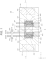
- FIG. 1 shows a plan view related to an overall configuration of a hydrogen production apparatus 10 related to the first embodiment
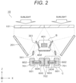
- FIG. 2 shows a cross-sectional view as seen along the line A-A' of FIG. 1 .
- 101 is a lens A
- 201 is a reflecting mirror
- 301 is a wavelength separation filter
- 401 is an infrared light conversion unit
- 402 is a lens B
- 501 is an ultraviolet light conversion unit
- 601 is a photocatalyst
- 602 is an auxiliary catalyst (for hydrogen)
- 603 is an auxiliary catalyst (for oxygen)
- 604 is a substrate
- 701 is a pipe on the hydrogen gas generation side
- 702 is a pipe on the oxygen gas generation side
- 703 is a water/gas separation mechanism unit separating water from a hydrogen gas or an oxygen gas.
- the hydrogen production apparatus 10 related to the present embodiment has a configuration symmetric in the left and right portions with respect to the center line M-M' shown in FIG. 1 .
- explanation will be given mainly with respect to a configuration on the left side of FIG. 1 and FIG. 2 in the explanation hereinafter, the same will be applicable with respect to a configuration on the right side.
- the lens A: 101 is a quartz Fresnel lens having a wide wavelength transmittivity.
- the lens A: 101 is not limited to the quartz Fresnel lens, and may be configured by a convex lens or a lens having a nonlinear curved surface, and so on.
- the sunlight having entered the lens A: 101 is condensed on the surface of the reflecting mirror 201 that has a smaller surface area than the lens A: 101 and is disposed to incline with respect to the lens A: 101.
- the reflecting mirror 201 is a concave mirror or a reflecting mirror, the reflecting mirror 21 being formed by a nonlinear curved surface, reflects the sunlight condensed by the lens A: 101, and condenses the same on the surface of the wavelength separation filter 301.
- the wavelength separation filter 301 allows the infrared light to transmit therethrough, and reflects the visible light and the ultraviolet light having a shorter wavelength than the infrared light.
- the infrared light having transmitted the wavelength separation filter 301 enters the infrared light conversion unit 401.
- the infrared light conversion unit 401 is formed by a configuration of forming a material emitting the visible light having a shorter wavelength than the infrared light when the infrared light enters (for example, the surface of a photonic crystalline body obtained by parallel arrangement of a number of quadrangular nanopillars with approximately 200 nm length of one side and approximately 500 nm height formed of Si and the like on a plane at 400 nm interval, the surface of one obtained by spreading circular nanoholes with approximately 500 nm diameter in a similar manner or a photonic crystalline body having a structure capable of changing the property of the semiconductor by applying voltage to the circular nanoholes and adjusting the wavelength of the reflected light, or a fluorescent agent emitting visible light by irradiation of the infrared light (light upconversion material), and so on) on the substrate. That is to say, by entering of the infrared light
- the infrared light conversion unit 401 when it is required to heat the infrared light conversion unit 401 in order to generate the visible light from the infrared light having entered, the infrared light conversion unit 401 can be configured to include a heating unit inside it.
- FIG. 3 shows an enlarged region surrounded by the dotted line B in FIG. 2 .
- the infrared light having transmitted the wavelength separation filter 301 enters the infrared light conversion unit 401, and the visible light generated in the infrared light conversion unit 401 enters the lens B: 402, and is condensed on the surface of the photocatalyst 601 and the auxiliary catalyst (for hydrogen) 602 and the auxiliary catalyst (for oxygen) 603, the auxiliary catalyst (for hydrogen) 602 and the auxiliary catalyst (for oxygen) 603 being formed at both ends of the photocatalyst 601.
- the infrared light conversion unit 401 is disposed to incline with respect to the wavelength separation filter 301 and the lens B: 402.
- the visible light and the ultraviolet light having not transmitted the wavelength separation filter 301 out of the sunlight having entered the wavelength separation filter 301 are reflected by the wavelength separation filter 301 and enter the ultraviolet light conversion unit 501.
- a fluorescent agent emitting a fluorescent light (visible light) when the ultraviolet light is irradiated is coated on the surface of the base material.
- the visible light out of the visible light and the ultraviolet light having entered the ultraviolet light conversion unit 501 is reflected at the surface of the ultraviolet light conversion unit 501 with the optical path being converted, and is condensed by the ultraviolet light conversion unit 501 on the surface of the photocatalyst 601 and the auxiliary catalyst (for hydrogen) 602 and the auxiliary catalyst (for oxygen) 603, the auxiliary catalyst (for hydrogen) 602 and the auxiliary catalyst (for oxygen) 603 being formed on both ends of the photocatalyst 601.
- a fluorescent light (visible light) is generated from the fluorescent agent coated on the surface of the base material of the ultraviolet light conversion unit 501, and a part of the fluorescent light (visible light) is condensed on the surface of the photocatalyst 601 and the auxiliary catalyst (for hydrogen) 602 and the auxiliary catalyst (for oxygen) 603, the auxiliary catalyst (for hydrogen) 602 and the auxiliary catalyst (for oxygen) 603 being formed on both ends of the photocatalyst 601.
- FIG. 4 shows the detail of a portion including the photocatalyst 601 surrounded by the dotted line C in FIG. 2 .
- the photocatalyst 601, the auxiliary catalyst (for hydrogen) 602 formed at one end of the photocatalyst 601, and the auxiliary catalyst (for oxygen) 603 formed at the other end of the photocatalyst 601 are formed on the substrate 604.
- the end of the photocatalyst 601 on a side where the auxiliary catalyst (for hydrogen) 602 is formed is placed inside the pipe 701 on the hydrogen gas generation side along with the substrate 604, water flowing through the inside of the pipe 701 on the hydrogen gas generation side.
- the end of the photocatalyst 601 on a side where the auxiliary catalyst (for oxygen) 603 is formed is placed inside of the pipe 702 on the oxygen gas generation side along with the substrate 604, water flowing through the inside of the pipe 702 on the oxygen gas generation side.
- an electric potential difference is generated between the auxiliary catalyst (for hydrogen) 602 and the auxiliary catalyst (for oxygen) 603, an electric potential difference is generated.
- Gaps between the photocatalyst 601 and the substrate 604 and the pipe 701 on the hydrogen gas generation side and the pipe 702 on the oxygen gas generation side are sealed by seal members not illustrated in order that water flowing through the inside of the pipe 701 on the hydrogen gas generation side or the pipe 702 on the oxygen gas generation side does not leak to the outside.
- Material of the auxiliary catalyst is determined by combination with the photocatalyst.
- IrO 3 , BiVO 4 , CoO, CoOOH, and the like are used on the cathode pole side generating oxygen, and the photocatalyst material itself may be used on the anode side generating hydrogen.
- WO 3 PO 3 is used on the cathode side, and WO 3 is used on the anode side.
- TaON NiO is used on the cathode side, and WO 3 -supported TaON is used on the anode side.
- LaTiO 2 is used on the cathode side, and Pt-supported LaTiO 2 is used on the anode side.
- Y 2 Ti 2 O 2 S 5 IrO 2 is used on the cathode side, and Rh or Rh coated with Cr 2 O 3 is used on the anode side. Above are examples and appropriate combinations other than the above are to be selected and used.
- the visible light converted from the infrared light and condensed by the lens B: 402 out of the sunlight having entered the lens A: 101 and the visible light converted from the ultraviolet light by the ultraviolet light conversion unit 501 and the visible light reflected by the ultraviolet light conversion unit 501 out of the sunlight having entered the lens A: 101 enter the photocatalyst 601 and the auxiliary catalyst (for hydrogen) 602 and the auxiliary catalyst (for oxygen) 603 which are irradiated by these visible lights, the auxiliary catalyst (for hydrogen) 602 and the auxiliary catalyst (for oxygen) 603 being formed at both ends of the photocatalyst 601.
- the auxiliary catalyst (for hydrogen) 602 and the auxiliary catalyst (for oxygen) 603 being formed at both ends of the photocatalyst 601, water is decomposed and a hydrogen gas is generated in the inside of the pipe 701 on the hydrogen gas generation side, and water is decomposed and an oxygen gas is generated in the inside of the pipe 702 on the oxygen gas generation side.
- the hydrogen gas generated inside of the pipe 701 on the hydrogen gas generation side flows along with the water, the hydrogen gas is separated from the water in the water/gas separation mechanism unit 703, and the hydrogen gas is recovered.
- the oxygen gas generated inside of the pipe 702 on the oxygen gas generation side flows along with water, the oxygen gas is separated from the water in the water/gas separation mechanism unit 703, and the oxygen gas is recovered.
- the present embodiment is to include a case of arranging a mechanism applying a weak external voltage less than 0.5 V. Further, the present embodiment is to include also a case water is made an electrolyte solution by an additive in order to promote the reaction.
- the utilization efficiency of the sunlight in the hydrogen production apparatus 10 could be improved by converting to the visible light and using respective components of the infrared light and the ultraviolet light not capable of activating the photocatalyst as it is and not contributing to generation of the hydrogen gas out of the sunlight entering the hydrogen production apparatus 10.
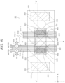
- FIG. 5 is a plan view showing an overall configuration of a hydrogen production apparatus 20 related to the second embodiment.
- the configuration of the hydrogen production apparatus 20 related to the present embodiment since the configuration of the optical system irradiating the sunlight having entered the lens A: 101 to the photocatalyst 601 through the lens B: 402 and the configuration of the optical system irradiating the sunlight having entered the lens A: 101 to the photocatalyst 601 through the ultraviolet light conversion unit 501 are same with the configuration of the hydrogen production apparatus 10 explained in the first embodiment, explanation thereof will be omitted.
- the configuration of a portion including the photocatalyst 601 corresponding to the portion surrounded by the dotted line C of FIG. 2 in the first embodiment is different from the first embodiment.
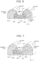
- the detail of the portion including the photocatalyst 601 corresponding to the portion surrounded by the dotted line C of FIG. 2 in the cross section D-D' of FIG. 5 and related to the present embodiment will be shown in the perspective view of FIG. 6 .
- the pipe 701 on the hydrogen gas generation side and the pipe 702 on the oxygen gas generation side on both sides of the photocatalyst 601 are disposed to be apart from each other.
- the present embodiment is configured such that a pipe 701-1 on the hydrogen gas generation side and a pipe 702-1 on the oxygen gas generation side are connected to each other by an intermediate section 710 and the entirety of the photocatalyst 601 is placed in water.
- water flowing through the pipe 701-1 on the hydrogen gas generation side and water flowing through the pipe 702-1 on the oxygen gas generation side come to be mixed with each other.
- the gap between the intermediate section 710 and the photocatalyst 601 therebeneath to be narrow the mixed volume of the water flowing through each pipe is reduced.
- the amount of the oxygen gas flowing in to the side of the pipe 701-1 on the hydrogen gas generation side and the amount of the hydrogen gas flowing in to the side of the water flowing through the pipe 702-1 on the oxygen gas generation side can be reduced, and reduction in yield of the hydrogen gas and the oxygen gas separated by the water/gas separation mechanism unit 703 can be made small to an ignorable degree.
- the configuration can be simplified by dispensing with such configuration of preventing water leakage in the gaps between the photocatalyst 601 and the pipe 701 on the hydrogen gas generation side and the pipe 702 on the oxygen gas generation side as the configuration of the first embodiment.
- FIG. 7 A modification of the second embodiment is shown in FIG. 7 .
- the configuration on the side of a pipe 702-2 on the oxygen gas generation side and the configuration of connecting a pipe 701-2 on the hydrogen gas generation side and the pipe 702-2 on the oxygen gas generation side to each other by the intermediate section 710 are same, the configuration of the inside of the pipe 701-2 on the hydrogen gas generation side is different.
- the present embodiment is configured such that, in the inside of the pipe 701-2 on the hydrogen gas generation side, the auxiliary catalyst (for hydrogen) 602 of FIG. 6 is eliminated, an opposite electrode 606 formed of Pt and the like is arranged instead of the auxiliary catalyst (for hydrogen) 602, and an ion-exchanging membrane 607 is disposed between the opposite electrode 606 and the photocatalyst 601 and the substrate 604.
- the ion-exchanging membrane 607 has a property of allowing a counter-ion to transmit therethrough.
- an auxiliary catalyst (the auxiliary catalyst (for oxygen) 603 in the example of FIG. 7 ) only has to be formed only on one end side of the photocatalyst 601 (on the side of the pipe 702-2 on the oxygen gas generation side in the configuration shown in FIG. 7 )
- the working man-hour is reduced and the manufacturing method is simplified compared to such configuration of forming the photocatalysts respectively in both ends of the photocatalyst 601 as shown in FIG. 6 .
- auxiliary catalyst combined with the photocatalyst 601 is reduced to one kind from two kinds of the case of FIG. 6 , selection of the material of the photocatalyst 601 and the auxiliary catalyst becomes easy.
- FIG. 8 A third embodiment of the present invention will be explained using FIG. 8 to FIG. 11 .
- the first and second embodiments are configured such that the visible light and the ultraviolet light having been reflected by the wavelength separation filter 301 are allowed to enter the ultraviolet light conversion unit 501, the visible light is reflected, and the ultraviolet light is converted to a fluorescent light.
- the present embodiment is configured such that conversion of the wavelength of the ultraviolet light is not exerted, and a diffracted light according to the wavelength is generated using a wavelength separation plate.
- FIG. 8 shows a plan view of a hydrogen production apparatus 30 related to the present embodiment
- FIG. 9 shows a cross-sectional view as seen along the line E-E' in FIG. 8 .
- the configuration of the hydrogen production apparatus 30 related to the present embodiment is different from the configuration explained in the first and second embodiments in terms of processing of the light having the wavelength region from the visible light to the ultraviolet light separated by the wavelength separation filter 301 out of the sunlight having entered the lens A: 101 and having been reflected by the reflecting mirror 201.
- the configuration of the optical system that the visible light generated from the infrared light conversion unit 401 where the infrared light having transmitted the wavelength separation filter 301 out of the sunlight having entered the lens A: 101 and having been reflected by the reflecting mirror 201 entered is irradiated to the photocatalyst 601 through the lens B: 402 is same with the configuration of the hydrogen production apparatus 10 explained in the first embodiment, and therefore explanation thereof will be omitted.
- the light having been reflected by the wavelength separation filter 301 and having the wavelength region from the visible light to the ultraviolet light enters a wavelength separation unit (monochromater) 502 at a diffraction angle.
- FIG. 10 shows an enlarged view of a portion surrounded by the dotted line F in FIG. 9 .
- the light having been reflected by the wavelength separation filter 301 and having the wavelength region from the visible light to the ultraviolet light enters the wavelength separation unit (monochromater) 502, is emitted from the wavelength separation unit (monochromater) 502 at a diffraction angle according to the wavelength, and enters the surface of a photocatalyst 601-1.
- the angle between the wavelength separation filter 301 and the surface of the photocatalyst 601-1 is adjusted so that the diffracted light generated by the light having entered from the wavelength separation filter 301 advances in the direction of the surface of the photocatalyst 601-1.
- the emission angle from the wavelength separation unit (monochromater) 502 changes according to the wavelength, the light having a comparatively short wavelength (ultraviolet light) enters the upper side of the photocatalyst 601-1 in the example of FIG. 10 , and the light having a comparatively long wavelength (visible light) enters the lower side of the photocatalyst 601-1.
- the photocatalyst 601-1 is formed of material having sensitivity to the visible light.
- a wavelength conversion layer 503 configured of material converting the ultraviolet light to the visible light is formed at a portion on the upper side where the light having a comparatively short wavelength (ultraviolet light) enters.
- the ultraviolet light having entered the wavelength conversion layer 503 is converted to the visible light, and reaches the photocatalyst 601-1 below the wavelength conversion layer 503.
- the light having a comparatively long wavelength visible light enters a portion on the lower side and formed of material having sensitivity to the visible light.
- the ultraviolet light out of the sunlight having entered the lens A: 101 is irradiated to the photocatalyst 601-1 along with the visible light without converting the wavelength, and therefore reduction of the light quantity irradiated to the photocatalyst 601-1 out of the sunlight having entered the lens A: 101 can be suppressed.
- a layer of an ultraviolet light-sensitive photocatalyst is formed instead of the wavelength conversion layer 503 at a portion of FIG. 10 where the wavelength conversion layer 503 is formed and the photocatalyst reaction is generated directly by the ultraviolet light having entered the portion in the relevant part.
- the portion of the wavelength conversion layer 503 where the ultraviolet light enters by a photocatalyst formed of material having sensitivity to the ultraviolet light by substituting the portion of the wavelength conversion layer 503 where the ultraviolet light enters by a photocatalyst formed of material having sensitivity to the ultraviolet light, the ultraviolet light having been diffracted by the wavelength separation unit (monochromater) 502 and having entered the portion on the upper side of the photocatalyst 601-1 can be detected as it is without converting the wavelength.
- the portion on the lower side where the light having a comparatively long wavelength (visible light) enters is formed of material having sensitivity to the visible light similarly to the photocatalyst 601 explained in the third embodiment.
- the ultraviolet light out of the sunlight having entered the lens A: 101 is irradiated to the photocatalyst 601-1 along with the visible light without converting the wavelength, and therefore reduction of the light quantity irradiated to the photocatalyst 601-1 out of the sunlight having entered the lens A: 101 can be suppressed.
- FIG. 11 shows a plan view of a hydrogen production apparatus 40 related to the present modification as a second modification of the third embodiment.
- the configuration of the photocatalyst 601-1 and its surroundings in FIG. 9 of the third embodiment corresponding to G-G' cross section of FIG. 11 is made such that the pipe 701-1 on the hydrogen gas generation side and the pipe 702-1 on the oxygen gas generation side are connected to each other by the intermediate section 710 and the entirety of the photocatalyst 601-1 is placed in water similarly to those explained using FIG. 6 in the second embodiment.
- the present modification is configured such that the entirety of the photocatalyst 601 is placed in water
- the configuration can be simplified by a portion that such configuration of preventing water leakage in the gaps between the photocatalyst 601-1 and the pipe 701 on the hydrogen gas generation side and the pipe 702 on the oxygen gas generation side as the configuration of the third embodiment is not required.
- auxiliary catalyst combined with the photocatalyst 601-1 is reduced to one kind as shown in FIG. 7 from two kinds of the case of FIG. 6 , selection of the material of the photocatalyst 601-1 and the auxiliary catalyst becomes easy.
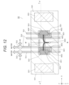
- FIG. 12 A fourth embodiment of the present invention will be explained using FIG. 12 to FIG. 14 .
- the present embodiment is different from the configuration explained in the first to third embodiments in that the visible light emitted from the infrared light conversion unit 401 is configured to be irradiated to the photocatalyst 601 using an optical fiber.
- FIG. 12 shows a plan view of a hydrogen production apparatus 50 related to the present embodiment
- FIG. 13 shows a cross-sectional view as seen along the line H-H' in FIG. 12 .
- the configuration of the optical system allowing the light having the wavelength range from the visible light to the ultraviolet light separated by the wavelength separation filter 301 out of the sunlight having entered the lens A: 101 and having been reflected by the reflecting mirror 201 to enter the ultraviolet light conversion unit 501 and irradiating the visible light emitted from the ultraviolet light conversion unit 501 to the photocatalyst 601 and the configuration of the optical system up to allowing the infrared light having transmitted the wavelength separation filter 301 out of the sunlight having entered the lens A: 101 and having been reflected by the reflecting mirror 201 to enter the lens B: 402 from the infrared light conversion unit 401 are same to the configuration of the hydrogen production apparatus 10 explained in the first embodiment, and therefore explanation thereof will be omitted.
- the hydrogen production apparatus 50 related to the present embodiment is different from the configuration of the first to third embodiments in terms of the positional relation of the lens B: 402 with respect to the infrared light conversion unit 401, and a tip portion 403 of an optical fiber 404 is disposed on the opposite side of the infrared light conversion unit 401 across the lens B: 402.
- the optical fiber 404 is disposed between the lens B: 402 and the photocatalyst 601.
- the visible light generated by the infrared light conversion unit 401 by the infrared light having transmitted the wavelength separation filter 301 and having entered the infrared light conversion unit 401 enters the lens B: 402, and the visible light having emitted from the lens B: 402 is condensed on the tip portion 403 of the optical fiber 404.
- the light condensed on the tip portion 403 is emitted to the photocatalyst 601 side from the opposite side end through the optical fiber 404.
- the optical fiber 404 is branched in the middle as shown in FIG. 13 and emits the visible light also to the side of the other photocatalyst 601, however, illustration thereof is omitted in FIG. 14 .
- an optical path can be set without been affected by a structure between the lens B: 402 and the photocatalyst 601, and the visible light generated by the infrared light conversion unit 401 can be irradiated surely to the photocatalyst 601.
- the pipe 701 on the hydrogen gas generation side and the pipe 702 on the oxygen gas generation side can employ such configuration that the pipe 701-1 on the hydrogen gas generation side and the pipe 702-1 on the oxygen gas generation side are connected to each other by the intermediate section 710 and the entirety of the photocatalyst 601 is placed in water as explained in the second embodiment using FIG. 6 , or such configuration as shown in FIG. 7 as explained in the modification of the second embodiment.
- the ultraviolet light conversion unit 501 may be substituted by such wavelength separation unit (monochromater) 502 as explained in the third embodiment and may be combined to such configuration of forming the wavelength conversion layer 503 in a part of the photocatalyst 601-1 as explained in FIG. 10 .
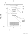
- FIG. 15 and FIG. 16 A fifth embodiment of the present invention will be explained using FIG. 15 and FIG. 16 .
- FIG. 15 is a plan view of a hydrogen production apparatus 60 related to the present embodiment
- FIG. 16 is a cross-sectional view as seen along the line J-J' in FIG. 15 .
- the hydrogen production apparatus 60 related to the present embodiment is common with the hydrogen production apparatus 10 explained in the first embodiment in terms of using the lens A: 101, but is different from the hydrogen production apparatus 10 explained in the first embodiment with respect to the route of the light having been emitted from the lens A: 101.
- the hydrogen production apparatus 60 related to the present embodiment includes a wavelength separation mechanism (monochromater type) 202, a lens C (infrared light) 302, a lens D (visible light) 303, a lens E (ultraviolet light) 304, the infrared light conversion unit 401, a condensing mirror B: 406, an ultraviolet light conversion unit 504, a condensing mirror D: 505, the photocatalyst 601, the auxiliary catalyst (for hydrogen) 602, the auxiliary catalyst (for oxygen) 603, the substrate 604, the pipe 701 on the hydrogen gas generation side, and the pipe 702 on the oxygen gas generation side.
- a wavelength separation mechanism monochromater type
- the pipe 701 on the hydrogen gas generation side and the pipe 702 on the oxygen gas generation side are connected to the water/gas separation mechanism unit 703 and the hydrogen gas and the oxygen gas are taken out in as similar manner to the hydrogen production apparatus 10 of the first embodiment explained in FIG. 1 .
- the sunlight having entered the lens A: 101 is condensed on and irradiated to the wavelength separation mechanism 202.
- the sunlight having been condensed on and irradiated to the wavelength separation mechanism 202 is emitted by the wavelength separation mechanism 202 at an angle according to the wavelength.
- the infrared light having a long wavelength is emitted to the direction of the lens C (infrared light) 302
- the visible light is emitted to the direction of the lens D (visible light) 303
- the ultraviolet light is emitted to the direction of the lens E (ultraviolet light) 304.
- the infrared light having entered the lens C (infrared light) 302 is emitted and converged to the direction of the infrared light conversion unit 401, and enters the infrared light conversion unit 401.
- Visible light is generated from the infrared light conversion unit 401 by entering of the infrared light, and the generated visible light is emitted to the direction of the condensing mirror B: 406, and is condensed on and irradiated to the surface of the photocatalyst 601 by the condensing mirror B: 406.
- the visible light having entered the lens D (visible light) 303 is emitted and converged to the direction of the photocatalyst 601, and enters the photocatalyst 601.
- the ultraviolet light having entered the lens E (ultraviolet light) 304 is emitted and converged to the direction of the ultraviolet light conversion unit 504, and enters the ultraviolet light conversion unit 504. Visible light is generated from the ultraviolet light conversion unit 504 by entering of the ultraviolet light, and the generated visible light is emitted to the direction of the condensing mirror D: 505, and is condensed on and irradiated to the surface of the photocatalyst 601 by the condensing mirror D: 505.
- the auxiliary catalyst (for hydrogen) 602 and the auxiliary catalyst (for oxygen) 603 being formed at both ends of the photocatalyst 601, water is decomposed and a hydrogen gas is generated inside of the pipe 701 on the hydrogen gas generation side, and water is decomposed and an oxygen gas is generated inside of the pipe 702 on the oxygen gas generation side.
- the hydrogen gas generated inside of the pipe 701 on the hydrogen gas generation side flows along with water, the hydrogen gas is separated from the water in the water/gas separation mechanism unit 703 explained in the first embodiment using FIG. 1 , and the hydrogen gas is recovered.
- the oxygen gas generated inside of the pipe 702 on the oxygen gas generation side flows along with water, the oxygen gas is separated from the water in the water/gas separation mechanism unit 703, and the oxygen gas is recovered.
- the utilization efficiency of the sunlight in the hydrogen production apparatus 10 can be improved by converting the infrared light and the ultraviolet light to the visible light out of the sunlight entering the hydrogen production apparatus 10 and using respective components which are not capable of activating the photocatalyst as it is and not contributing to generation of a hydrogen gas.
- the pipe 701 on the hydrogen gas generation side and the pipe 702 on the oxygen gas generation side can employ such configuration that the pipe 701-1 on the hydrogen gas generation side and the pipe 702-1 on the oxygen gas generation side are connected to each other by the intermediate section 710 and the entirety of the photocatalyst 601 is placed in water as explained in the second embodiment using FIG. 6 , or such configuration as shown in FIG. 7 as explained in the modification of the second embodiment.
- the ultraviolet light conversion unit 504 may be substituted by such wavelength separation unit (monochromater) 502 as explained in the third embodiment, the ultraviolet light is condensed on and irradiated to the region where the ultraviolet light-sensitive photocatalyst having sensitivity to the ultraviolet light is coated on the surface of the photocatalyst 601 by the condensing mirror D: 505, and such configuration of forming the wavelength conversion layer 503 in a part of the photocatalyst 601-1 as explained in FIG. 10 may be combined.
- wavelength separation unit monochromater
- a reflecting mirror reflecting the ultraviolet light is used instead of the ultraviolet light conversion unit 504, and the ultraviolet light is condensed on and irradiated to the region where the ultraviolet light-sensitive photocatalyst having sensitivity to the ultraviolet light is coated on the surface of the photocatalyst 601 by the condensing mirror D: 505.
Landscapes
- Chemical & Material Sciences (AREA)
- Organic Chemistry (AREA)
- Engineering & Computer Science (AREA)
- Chemical Kinetics & Catalysis (AREA)
- Inorganic Chemistry (AREA)
- Materials Engineering (AREA)
- Health & Medical Sciences (AREA)
- Electrochemistry (AREA)
- Metallurgy (AREA)
- Physics & Mathematics (AREA)
- Combustion & Propulsion (AREA)
- General Health & Medical Sciences (AREA)
- Toxicology (AREA)
- General Physics & Mathematics (AREA)
- Optics & Photonics (AREA)
- Electromagnetism (AREA)
- Catalysts (AREA)
Abstract
A hydrogen production apparatus including a photocatalyst and generating hydrogen from water includes a wavelength separation unit separating sunlight by wavelength, an infrared light conversion unit converting infrared light separated by the wavelength separation unit to visible light, and an ultraviolet light conversion unit converting ultraviolet light separated by the wavelength separation unit to visible light.
Description
- The present invention relates to a hydrogen production apparatus decomposing water with light and producing a hydrogen gas.
- With respect to the technology of decomposing water with the sunlight and producing hydrogen highly efficiently represented by a photocatalyst, it is desired to be applied as a renewable energy business and an environment business addressed to achievement of the ecosocialism infrastructure such as the hydrogen power generation and the hydrogen-fueled car achieving non-fossil fuel as a production technology for an inexpensive accumulable energy carrier not involving emission of CO2.
- Also, when a highly efficiently utilizing technology for the sunlight is developed, since it can be applied to production of useful material and so on by applying a photocatalyst decomposing a chemical substance having a large environmental effect, it is also expected that the technology is spread to surrounding industries such as a substance generation system.
- As a technology related to decomposing of water by the sunlight to generate hydrogen, in
Japanese Unexamined Patent Application Publication No. 2013-180245 - As a highly efficiently utilizing technology for the sunlight energy required in decomposing water by the sunlight and generating hydrogen, there has been in progress the development of a material having an active region in a visible light region (400 to 700 nm) with a higher light intensity of the sunlight spectrum instead of a material of a prior art (NaTaO3: 280 nm, TiO2: around 400 nm) becoming active in an ultraviolet light region with respect to the frequency region of the irradiation light where the photocatalyst reaction becomes active.
- However, the spectrum of the sunlight is spread largely not only to the ultraviolet light but also to the infrared light, and such energy has not been utilized. Also, since the energy of the infrared light of 1,000 nm or above is less than 1.23 V that is required for decomposition of water, it cannot be utilized for decomposition of water as it is. Thus, in a hydrogen production apparatus including a photocatalyst, it has not been possible to improve the light utilization efficiency.
- Even in
Japanese Unexamined Patent Application Publication No. 2013-180245 - The present invention is to provide a hydrogen production apparatus solving the problem of the prior art described above, highly efficiently utilizing wavelength components of a wide range from the ultraviolet light to the infrared light of the sunlight including the visible light, and improving the total light utilization efficiency compared to a prior art.
- In order to solve the problem described above, in the present invention, a hydrogen production apparatus including a photocatalyst and generating hydrogen from water is configured to include a wavelength separation unit separating sunlight by wavelength, an infrared light conversion unit converting infrared light separated by the wavelength separation unit to visible light, and an ultraviolet light conversion unit converting ultraviolet light separated by the wavelength separation unit to visible light.
- Also, in order to solve the problem described above, in the present invention, a hydrogen production apparatus is configured to include a photocatalyst generating a hydrogen gas from water by irradiating light, a pipe allowing water to flow through the inside, a wavelength separation unit separating sunlight by wavelength, a first optical system condensing on the photocatalyst and irradiating visible light obtained by separating sunlight by wavelength using the wavelength separation unit, a second optical system converting ultraviolet light obtained by separating sunlight by wavelength using the wavelength separation unit to visible light and condensing on and irradiating the visible light to the photocatalyst, and a third optical system converting infrared light obtained by separating sunlight by wavelength using the wavelength separation unit to visible light and condensing on and irradiating the visible light to the photocatalyst.
- Also, in order to solve the problem described above, in the present invention, a hydrogen production apparatus is configured to include a photocatalyst generating a hydrogen gas in water by irradiating visible light, a light irradiation unit irradiating visible light included in sunlight and visible light generated from light other than the visible light of the sunlight to the photocatalyst, and a water/gas separation mechanism unit separating a hydrogen gas from water, the hydrogen gas being generated by the photocatalyst, the visible light included in the sunlight and the generated visible light being irradiated to the photocatalyst from the light irradiation unit.
- And further, in order to solve the problem described above, in the present invention, a hydrogen production method for generating hydrogen from water by using a photocatalyst is comprising the steps of separating wavelength of sunlight to infrared light, visible light, and ultraviolet light with a wavelength separation unit, and condensing on and irradiating the lights separated by the wavelength of the sunlight with an optical unit to the photocatalyst disposed inside a pipe in which a water is flowing.
- According to the present invention, it is possible to provide a hydrogen production apparatus highly efficiently utilizing wavelength components of a wide range from the ultraviolet light to the infrared light of the sunlight including the visible light and improving the total light utilization efficiency compared to a prior art.
-
-
FIG. 1 is a plan view of a hydrogen production apparatus related to a first embodiment of the present invention; -
FIG. 2 is a cross-sectional view as seen along the line A-A' ofFIG. 1 ; -
FIG. 3 is a perspective view enlarging the section B ofFIG. 2 ; -
FIG. 4 is a perspective view enlarging the section C ofFIG. 2 ; -
FIG. 5 is a plan view of a hydrogen production apparatus related to a second embodiment of the present invention; -
FIG. 6 is a perspective view equivalent to the detail of the section C ofFIG. 4 of the first embodiment in the hydrogen production apparatus related to the second embodiment; -
FIG. 7 is a perspective view corresponding toFIG. 6 in a modification of the second embodiment; -
FIG. 8 is a plan view of a hydrogen production apparatus related to a third embodiment of the present invention; -
FIG. 9 is a cross-sectional view as seen along the line E-E' ofFIG. 8 ; -
FIG. 10 is a perspective view enlarging the section F ofFIG. 9 ; -
FIG. 11 is a plan view of a hydrogen production apparatus related to the second modification of the third embodiment; -
FIG. 12 is a plan view of a hydrogen production apparatus related to a fourth embodiment of the present invention; -
FIG. 13 is a cross-sectional view as seen along the line H-H' ofFIG. 12 ; -
FIG. 14 is a perspective view enlarging the section I ofFIG. 13 ; -
FIG. 15 is a plan view of a hydrogen production apparatus related to a fifth embodiment of the present invention; and -
FIG. 16 is a cross-sectional view as seen along the line J-J' ofFIG. 15 . - The present invention relates to a hydrogen production apparatus capable of efficiently separating and refining hydrogen from water by employing a configuration of solving a problem in combining an optical system and various functions with each other, the optical system efficiently converting the wavelength spectrum of the sunlight to an active region of the photocatalyst and condensing on the photocatalyst.
- That is to say, according to the present invention, a hydrogen production apparatus is enabled to efficiently separate and refine hydrogen from water by using a photocatalyst (TiO2, LaTiO2, TaON, Y2Ti2O5S2, Rh-doped SrTiO3, ZnRh2O4, Sm2Ti2O2S5, CuAgZnSnS4, and so on for example) having an active region in the visible light region (wavelength: 400 nm to 700 nm) where the energy level of the sunlight comes to a peak, and respectively converting the wavelength of light having a wavelength component of the ultraviolet light region and light having a wavelength component of the infrared light region out of the sunlight to light having a wavelength of the visible light region to irradiate to the photocatalyst along with the visible light from the sunlight.
- Embodiments of the present invention will be hereinafter explained in detail based on the drawings. In all drawings for explaining the present embodiment, those having a same function will be marked with a same reference sign, and repeated explanation thereof will be omitted in principle.
- However, the present invention is not to be interpreted to be limited to the description content of the embodiments hereinafter shown. A person with an ordinary skill in the art is to easily understand that the concrete configuration of the present invention can be altered within a range not departing from the thought or the gist of the present invention.
- A hydrogen production apparatus related to a first embodiment of the present invention will be explained using
FIG. 1 to FIG. 4 .FIG. 1 shows a plan view related to an overall configuration of ahydrogen production apparatus 10 related to the first embodiment, andFIG. 2 shows a cross-sectional view as seen along the line A-A' ofFIG. 1 . - In the configuration shown in
FIG. 1 andFIG. 2 , 101 is a lens A, 201 is a reflecting mirror, 301 is a wavelength separation filter, 401 is an infrared light conversion unit, 402 is a lens B, 501 is an ultraviolet light conversion unit, 601 is a photocatalyst, 602 is an auxiliary catalyst (for hydrogen), 603 is an auxiliary catalyst (for oxygen), 604 is a substrate, 701 is a pipe on the hydrogen gas generation side, 702 is a pipe on the oxygen gas generation side, and 703 is a water/gas separation mechanism unit separating water from a hydrogen gas or an oxygen gas. - The
hydrogen production apparatus 10 related to the present embodiment has a configuration symmetric in the left and right portions with respect to the center line M-M' shown inFIG. 1 . Although explanation will be given mainly with respect to a configuration on the left side ofFIG. 1 andFIG. 2 in the explanation hereinafter, the same will be applicable with respect to a configuration on the right side. - In the configuration shown in
FIG. 1 andFIG. 2 , the lens A: 101 is a quartz Fresnel lens having a wide wavelength transmittivity. However, the lens A: 101 is not limited to the quartz Fresnel lens, and may be configured by a convex lens or a lens having a nonlinear curved surface, and so on. The sunlight having entered the lens A: 101 is condensed on the surface of the reflectingmirror 201 that has a smaller surface area than the lens A: 101 and is disposed to incline with respect to the lens A: 101. - The reflecting
mirror 201 is a concave mirror or a reflecting mirror, the reflecting mirror 21 being formed by a nonlinear curved surface, reflects the sunlight condensed by the lens A: 101, and condenses the same on the surface of thewavelength separation filter 301. Thewavelength separation filter 301 allows the infrared light to transmit therethrough, and reflects the visible light and the ultraviolet light having a shorter wavelength than the infrared light. - The infrared light having transmitted the
wavelength separation filter 301 enters the infraredlight conversion unit 401. The infraredlight conversion unit 401 is formed by a configuration of forming a material emitting the visible light having a shorter wavelength than the infrared light when the infrared light enters (for example, the surface of a photonic crystalline body obtained by parallel arrangement of a number of quadrangular nanopillars with approximately 200 nm length of one side and approximately 500 nm height formed of Si and the like on a plane at 400 nm interval, the surface of one obtained by spreading circular nanoholes with approximately 500 nm diameter in a similar manner or a photonic crystalline body having a structure capable of changing the property of the semiconductor by applying voltage to the circular nanoholes and adjusting the wavelength of the reflected light, or a fluorescent agent emitting visible light by irradiation of the infrared light (light upconversion material), and so on) on the substrate. That is to say, by entering of the infrared light, visible light is generated from the infraredlight conversion unit 401. - Also, in the infrared
light conversion unit 401, when it is required to heat the infraredlight conversion unit 401 in order to generate the visible light from the infrared light having entered, the infraredlight conversion unit 401 can be configured to include a heating unit inside it. - The visible light generated in the infrared
light conversion unit 401 where the infrared light entered enters the lens B: 402.FIG. 3 shows an enlarged region surrounded by the dotted line B inFIG. 2 . The infrared light having transmitted thewavelength separation filter 301 enters the infraredlight conversion unit 401, and the visible light generated in the infraredlight conversion unit 401 enters the lens B: 402, and is condensed on the surface of thephotocatalyst 601 and the auxiliary catalyst (for hydrogen) 602 and the auxiliary catalyst (for oxygen) 603, the auxiliary catalyst (for hydrogen) 602 and the auxiliary catalyst (for oxygen) 603 being formed at both ends of thephotocatalyst 601. - In order that the infrared light having transmitted the
wavelength separation filter 301 enters more and that the visible light having been generated enters the lens B: 402 more, the infraredlight conversion unit 401 is disposed to incline with respect to thewavelength separation filter 301 and the lens B: 402. - On the other hand, the visible light and the ultraviolet light having not transmitted the
wavelength separation filter 301 out of the sunlight having entered thewavelength separation filter 301 are reflected by thewavelength separation filter 301 and enter the ultravioletlight conversion unit 501. In the ultravioletlight conversion unit 501, a fluorescent agent emitting a fluorescent light (visible light) when the ultraviolet light is irradiated is coated on the surface of the base material. - The visible light out of the visible light and the ultraviolet light having entered the ultraviolet
light conversion unit 501 is reflected at the surface of the ultravioletlight conversion unit 501 with the optical path being converted, and is condensed by the ultravioletlight conversion unit 501 on the surface of thephotocatalyst 601 and the auxiliary catalyst (for hydrogen) 602 and the auxiliary catalyst (for oxygen) 603, the auxiliary catalyst (for hydrogen) 602 and the auxiliary catalyst (for oxygen) 603 being formed on both ends of thephotocatalyst 601. On the other hand, by that the ultraviolet light enters the ultravioletlight conversion unit 501, a fluorescent light (visible light) is generated from the fluorescent agent coated on the surface of the base material of the ultravioletlight conversion unit 501, and a part of the fluorescent light (visible light) is condensed on the surface of thephotocatalyst 601 and the auxiliary catalyst (for hydrogen) 602 and the auxiliary catalyst (for oxygen) 603, the auxiliary catalyst (for hydrogen) 602 and the auxiliary catalyst (for oxygen) 603 being formed on both ends of thephotocatalyst 601. -
FIG. 4 shows the detail of a portion including thephotocatalyst 601 surrounded by the dotted line C inFIG. 2 . Thephotocatalyst 601, the auxiliary catalyst (for hydrogen) 602 formed at one end of thephotocatalyst 601, and the auxiliary catalyst (for oxygen) 603 formed at the other end of thephotocatalyst 601 are formed on thesubstrate 604. The end of thephotocatalyst 601 on a side where the auxiliary catalyst (for hydrogen) 602 is formed is placed inside thepipe 701 on the hydrogen gas generation side along with thesubstrate 604, water flowing through the inside of thepipe 701 on the hydrogen gas generation side. On the other hand, the end of thephotocatalyst 601 on a side where the auxiliary catalyst (for oxygen) 603 is formed is placed inside of thepipe 702 on the oxygen gas generation side along with thesubstrate 604, water flowing through the inside of thepipe 702 on the oxygen gas generation side. In this state, between the auxiliary catalyst (for hydrogen) 602 and the auxiliary catalyst (for oxygen) 603, an electric potential difference is generated. - Gaps between the
photocatalyst 601 and thesubstrate 604 and thepipe 701 on the hydrogen gas generation side and thepipe 702 on the oxygen gas generation side are sealed by seal members not illustrated in order that water flowing through the inside of thepipe 701 on the hydrogen gas generation side or thepipe 702 on the oxygen gas generation side does not leak to the outside. - Material of the auxiliary catalyst is determined by combination with the photocatalyst. For example, with respect to SrTiO3 having been doped, IrO3, BiVO4, CoO, CoOOH, and the like are used on the cathode pole side generating oxygen, and the photocatalyst material itself may be used on the anode side generating hydrogen. Also, with respect to WO3, PO3 is used on the cathode side, and WO3 is used on the anode side. Also, with respect to TaON, NiO is used on the cathode side, and WO3-supported TaON is used on the anode side. With respect to LaTiON, LaTiO2 is used on the cathode side, and Pt-supported LaTiO2 is used on the anode side. With respect to Y2Ti2O2S5, IrO2 is used on the cathode side, and Rh or Rh coated with Cr2O3 is used on the anode side. Above are examples and appropriate combinations other than the above are to be selected and used.
- In the configuration shown in
FIG. 4 , the visible light converted from the infrared light and condensed by the lens B: 402 out of the sunlight having entered the lens A: 101 and the visible light converted from the ultraviolet light by the ultravioletlight conversion unit 501 and the visible light reflected by the ultravioletlight conversion unit 501 out of the sunlight having entered the lens A: 101 enter thephotocatalyst 601 and the auxiliary catalyst (for hydrogen) 602 and the auxiliary catalyst (for oxygen) 603 which are irradiated by these visible lights, the auxiliary catalyst (for hydrogen) 602 and the auxiliary catalyst (for oxygen) 603 being formed at both ends of thephotocatalyst 601. - In the
photocatalyst 601 and the auxiliary catalyst (for hydrogen) 602 and the auxiliary catalyst (for oxygen) 603 where these visible lights have entered, the auxiliary catalyst (for hydrogen) 602 and the auxiliary catalyst (for oxygen) 603 being formed at both ends of thephotocatalyst 601, water is decomposed and a hydrogen gas is generated in the inside of thepipe 701 on the hydrogen gas generation side, and water is decomposed and an oxygen gas is generated in the inside of thepipe 702 on the oxygen gas generation side. - The hydrogen gas generated inside of the
pipe 701 on the hydrogen gas generation side flows along with the water, the hydrogen gas is separated from the water in the water/gasseparation mechanism unit 703, and the hydrogen gas is recovered. On the other hand, the oxygen gas generated inside of thepipe 702 on the oxygen gas generation side flows along with water, the oxygen gas is separated from the water in the water/gasseparation mechanism unit 703, and the oxygen gas is recovered. - Although the potential on the hydrogen generation electrode side is approximately zero, according to the kind of the catalyst, there is a case where the reaction becomes extremely slow or stops when the potential on the hydrogen generation electrode side is lower than the potential of water. Therefore, the present embodiment is to include a case of arranging a mechanism applying a weak external voltage less than 0.5 V. Further, the present embodiment is to include also a case water is made an electrolyte solution by an additive in order to promote the reaction.
- According to the present embodiment, the utilization efficiency of the sunlight in the
hydrogen production apparatus 10 could be improved by converting to the visible light and using respective components of the infrared light and the ultraviolet light not capable of activating the photocatalyst as it is and not contributing to generation of the hydrogen gas out of the sunlight entering thehydrogen production apparatus 10. - A second embodiment of the present invention will be explained using
FIG. 5 andFIG. 6 .
FIG. 5 is a plan view showing an overall configuration of ahydrogen production apparatus 20 related to the second embodiment. Of the configuration of thehydrogen production apparatus 20 related to the present embodiment, since the configuration of the optical system irradiating the sunlight having entered the lens A: 101 to thephotocatalyst 601 through the lens B: 402 and the configuration of the optical system irradiating the sunlight having entered the lens A: 101 to thephotocatalyst 601 through the ultravioletlight conversion unit 501 are same with the configuration of thehydrogen production apparatus 10 explained in the first embodiment, explanation thereof will be omitted. - In the present embodiment, the configuration of a portion including the
photocatalyst 601 corresponding to the portion surrounded by the dotted line C ofFIG. 2 in the first embodiment is different from the first embodiment. The detail of the portion including thephotocatalyst 601 corresponding to the portion surrounded by the dotted line C ofFIG. 2 in the cross section D-D' ofFIG. 5 and related to the present embodiment will be shown in the perspective view ofFIG. 6 . - In the first embodiment, the
pipe 701 on the hydrogen gas generation side and thepipe 702 on the oxygen gas generation side on both sides of thephotocatalyst 601 are disposed to be apart from each other. On the other hand, the present embodiment is configured such that a pipe 701-1 on the hydrogen gas generation side and a pipe 702-1 on the oxygen gas generation side are connected to each other by anintermediate section 710 and the entirety of thephotocatalyst 601 is placed in water. - With such configuration, water flowing through the pipe 701-1 on the hydrogen gas generation side and water flowing through the pipe 702-1 on the oxygen gas generation side come to be mixed with each other. However, according to the present embodiment, by setting the gap between the
intermediate section 710 and thephotocatalyst 601 therebeneath to be narrow, the mixed volume of the water flowing through each pipe is reduced. Thus, the amount of the oxygen gas flowing in to the side of the pipe 701-1 on the hydrogen gas generation side and the amount of the hydrogen gas flowing in to the side of the water flowing through the pipe 702-1 on the oxygen gas generation side can be reduced, and reduction in yield of the hydrogen gas and the oxygen gas separated by the water/gasseparation mechanism unit 703 can be made small to an ignorable degree. - Since the present embodiment is configured such that the entirety of the
photocatalyst 601 is placed in water, the configuration can be simplified by dispensing with such configuration of preventing water leakage in the gaps between thephotocatalyst 601 and thepipe 701 on the hydrogen gas generation side and thepipe 702 on the oxygen gas generation side as the configuration of the first embodiment. - A modification of the second embodiment is shown in
FIG. 7 . Compared to the configuration shown inFIG. 6 , with respect to the configuration shown inFIG. 7 , although the configuration on the side of a pipe 702-2 on the oxygen gas generation side and the configuration of connecting a pipe 701-2 on the hydrogen gas generation side and the pipe 702-2 on the oxygen gas generation side to each other by theintermediate section 710 are same, the configuration of the inside of the pipe 701-2 on the hydrogen gas generation side is different. - That is to say, the present embodiment is configured such that, in the inside of the pipe 701-2 on the hydrogen gas generation side, the auxiliary catalyst (for hydrogen) 602 of
FIG. 6 is eliminated, anopposite electrode 606 formed of Pt and the like is arranged instead of the auxiliary catalyst (for hydrogen) 602, and an ion-exchangingmembrane 607 is disposed between theopposite electrode 606 and thephotocatalyst 601 and thesubstrate 604. - The ion-exchanging
membrane 607 has a property of allowing a counter-ion to transmit therethrough. By separating the pipe 701-2 on the hydrogen gas generation side and the pipe 702-2 on the oxygen gas generation side from each other by this ion-exchangingmembrane 607, oxygen gas and hydrogen gas can be separately generated in the pipe 701-2 on the hydrogen gas generation side and the pipe 702-2 on the oxygen gas generation side. - According to the present modification, in addition to the effect explained in the second embodiment, since an auxiliary catalyst (the auxiliary catalyst (for oxygen) 603 in the example of
FIG. 7 ) only has to be formed only on one end side of the photocatalyst 601 (on the side of the pipe 702-2 on the oxygen gas generation side in the configuration shown inFIG. 7 ), the working man-hour is reduced and the manufacturing method is simplified compared to such configuration of forming the photocatalysts respectively in both ends of thephotocatalyst 601 as shown inFIG. 6 . - Also, since the auxiliary catalyst combined with the
photocatalyst 601 is reduced to one kind from two kinds of the case ofFIG. 6 , selection of the material of thephotocatalyst 601 and the auxiliary catalyst becomes easy. - A third embodiment of the present invention will be explained using
FIG. 8 to FIG. 11 . - The first and second embodiments are configured such that the visible light and the ultraviolet light having been reflected by the
wavelength separation filter 301 are allowed to enter the ultravioletlight conversion unit 501, the visible light is reflected, and the ultraviolet light is converted to a fluorescent light. On the other hand, the present embodiment is configured such that conversion of the wavelength of the ultraviolet light is not exerted, and a diffracted light according to the wavelength is generated using a wavelength separation plate. -
FIG. 8 shows a plan view of ahydrogen production apparatus 30 related to the present embodiment, andFIG. 9 shows a cross-sectional view as seen along the line E-E' inFIG. 8 . - The configuration of the
hydrogen production apparatus 30 related to the present embodiment is different from the configuration explained in the first and second embodiments in terms of processing of the light having the wavelength region from the visible light to the ultraviolet light separated by thewavelength separation filter 301 out of the sunlight having entered the lens A: 101 and having been reflected by the reflectingmirror 201. - On the other hand, the configuration of the optical system that the visible light generated from the infrared
light conversion unit 401 where the infrared light having transmitted thewavelength separation filter 301 out of the sunlight having entered the lens A: 101 and having been reflected by the reflectingmirror 201 entered is irradiated to thephotocatalyst 601 through the lens B: 402 is same with the configuration of thehydrogen production apparatus 10 explained in the first embodiment, and therefore explanation thereof will be omitted. - In the configuration shown in
FIG. 9 , the light having been reflected by thewavelength separation filter 301 and having the wavelength region from the visible light to the ultraviolet light enters a wavelength separation unit (monochromater) 502 at a diffraction angle. -
FIG. 10 shows an enlarged view of a portion surrounded by the dotted line F inFIG. 9 . The light having been reflected by thewavelength separation filter 301 and having the wavelength region from the visible light to the ultraviolet light enters the wavelength separation unit (monochromater) 502, is emitted from the wavelength separation unit (monochromater) 502 at a diffraction angle according to the wavelength, and enters the surface of a photocatalyst 601-1. Here, with respect to the wavelength separation unit (monochromater) 502, the angle between thewavelength separation filter 301 and the surface of the photocatalyst 601-1 is adjusted so that the diffracted light generated by the light having entered from thewavelength separation filter 301 advances in the direction of the surface of the photocatalyst 601-1. - With respect to the diffracted light generated in the wavelength separation unit (monochromater) 502, the emission angle from the wavelength separation unit (monochromater) 502 changes according to the wavelength, the light having a comparatively short wavelength (ultraviolet light) enters the upper side of the photocatalyst 601-1 in the example of
FIG. 10 , and the light having a comparatively long wavelength (visible light) enters the lower side of the photocatalyst 601-1. - Here, in a similar manner to the
photocatalyst 601 explained in the first and second embodiments, the photocatalyst 601-1 is formed of material having sensitivity to the visible light. In a part of the photocatalyst 601-1, as enlargingly illustrated on the right side ofFIG. 10 , awavelength conversion layer 503 configured of material converting the ultraviolet light to the visible light is formed at a portion on the upper side where the light having a comparatively short wavelength (ultraviolet light) enters. The ultraviolet light having entered thewavelength conversion layer 503 is converted to the visible light, and reaches the photocatalyst 601-1 below thewavelength conversion layer 503. On the other hand, the light having a comparatively long wavelength (visible light) enters a portion on the lower side and formed of material having sensitivity to the visible light. - Thus, by configuring the position for entering the photocatalyst 601-1 to be differentiated according to the wavelength and forming the
wavelength conversion layer 503 at a portion where the ultraviolet light enters out of the surface of the photocatalyst 601-1, the ultraviolet light out of the sunlight having entered the lens A: 101 is irradiated to the photocatalyst 601-1 along with the visible light without converting the wavelength, and therefore reduction of the light quantity irradiated to the photocatalyst 601-1 out of the sunlight having entered the lens A: 101 can be suppressed. - Further, it is also possible to configure that a layer of an ultraviolet light-sensitive photocatalyst is formed instead of the
wavelength conversion layer 503 at a portion ofFIG. 10 where thewavelength conversion layer 503 is formed and the photocatalyst reaction is generated directly by the ultraviolet light having entered the portion in the relevant part. - Explanation will be made on an example of substituting the
wavelength conversion layer 503 of the photocatalyst 601-1 shown inFIG. 10 by a material having sensitivity to the ultraviolet light as a first modification of the third embodiment. - In the configuration of the photocatalyst 601-1 enlargingly shown on the right side of
FIG. 10 , by substituting the portion of thewavelength conversion layer 503 where the ultraviolet light enters by a photocatalyst formed of material having sensitivity to the ultraviolet light, the ultraviolet light having been diffracted by the wavelength separation unit (monochromater) 502 and having entered the portion on the upper side of the photocatalyst 601-1 can be detected as it is without converting the wavelength. On the other hand, the portion on the lower side where the light having a comparatively long wavelength (visible light) enters is formed of material having sensitivity to the visible light similarly to thephotocatalyst 601 explained in the third embodiment. - Thus, by configuring the surface of the photocatalyst 601-1 with the material having sensitivity according to the wavelength of the entering light, the ultraviolet light out of the sunlight having entered the lens A: 101 is irradiated to the photocatalyst 601-1 along with the visible light without converting the wavelength, and therefore reduction of the light quantity irradiated to the photocatalyst 601-1 out of the sunlight having entered the lens A: 101 can be suppressed.
-
FIG. 11 shows a plan view of ahydrogen production apparatus 40 related to the present modification as a second modification of the third embodiment. - With respect to the
hydrogen production apparatus 40 related to the present modification, the configuration of the photocatalyst 601-1 and its surroundings inFIG. 9 of the third embodiment corresponding to G-G' cross section ofFIG. 11 is made such that the pipe 701-1 on the hydrogen gas generation side and the pipe 702-1 on the oxygen gas generation side are connected to each other by theintermediate section 710 and the entirety of the photocatalyst 601-1 is placed in water similarly to those explained usingFIG. 6 in the second embodiment. - Since the present modification is configured such that the entirety of the
photocatalyst 601 is placed in water, the configuration can be simplified by a portion that such configuration of preventing water leakage in the gaps between the photocatalyst 601-1 and thepipe 701 on the hydrogen gas generation side and thepipe 702 on the oxygen gas generation side as the configuration of the third embodiment is not required. - Further, it is also possible to be configured as explained using
FIG. 7 as a modification of the third embodiment. - By such configuration as shown in
FIG. 7 , the working man-hour is reduced and the manufacturing method is simplified compared to such configuration of forming theauxiliary catalysts FIG. 9 . - Also, since the auxiliary catalyst combined with the photocatalyst 601-1 is reduced to one kind as shown in
FIG. 7 from two kinds of the case ofFIG. 6 , selection of the material of the photocatalyst 601-1 and the auxiliary catalyst becomes easy. - A fourth embodiment of the present invention will be explained using
FIG. 12 to FIG. 14 . - The present embodiment is different from the configuration explained in the first to third embodiments in that the visible light emitted from the infrared
light conversion unit 401 is configured to be irradiated to thephotocatalyst 601 using an optical fiber. -
FIG. 12 shows a plan view of ahydrogen production apparatus 50 related to the present embodiment, andFIG. 13 shows a cross-sectional view as seen along the line H-H' inFIG. 12 . - In the configuration of the
hydrogen production apparatus 50 shown inFIG. 12 andFIG. 13 , the configuration of the optical system allowing the light having the wavelength range from the visible light to the ultraviolet light separated by thewavelength separation filter 301 out of the sunlight having entered the lens A: 101 and having been reflected by the reflectingmirror 201 to enter the ultravioletlight conversion unit 501 and irradiating the visible light emitted from the ultravioletlight conversion unit 501 to thephotocatalyst 601 and the configuration of the optical system up to allowing the infrared light having transmitted thewavelength separation filter 301 out of the sunlight having entered the lens A: 101 and having been reflected by the reflectingmirror 201 to enter the lens B: 402 from the infraredlight conversion unit 401 are same to the configuration of thehydrogen production apparatus 10 explained in the first embodiment, and therefore explanation thereof will be omitted. - As shown in
FIG. 12 , thehydrogen production apparatus 50 related to the present embodiment is different from the configuration of the first to third embodiments in terms of the positional relation of the lens B: 402 with respect to the infraredlight conversion unit 401, and atip portion 403 of anoptical fiber 404 is disposed on the opposite side of the infraredlight conversion unit 401 across the lens B: 402. - As shown in the cross-sectional view of
FIG. 13 , in thehydrogen production apparatus 50 related to the present embodiment, theoptical fiber 404 is disposed between the lens B: 402 and thephotocatalyst 601. In such configuration, as shown inFIG. 14 enlargingly illustrating the portion surrounded by the dotted line I ofFIG. 13 , the visible light generated by the infraredlight conversion unit 401 by the infrared light having transmitted thewavelength separation filter 301 and having entered the infraredlight conversion unit 401 enters the lens B: 402, and the visible light having emitted from the lens B: 402 is condensed on thetip portion 403 of theoptical fiber 404. The light condensed on thetip portion 403 is emitted to thephotocatalyst 601 side from the opposite side end through theoptical fiber 404. In fact, theoptical fiber 404 is branched in the middle as shown inFIG. 13 and emits the visible light also to the side of theother photocatalyst 601, however, illustration thereof is omitted inFIG. 14 . - According to the present embodiment, by employing the configuration of irradiating the visible light to the
photocatalyst 601 using theoptical fiber 404, an optical path can be set without been affected by a structure between the lens B: 402 and thephotocatalyst 601, and the visible light generated by the infraredlight conversion unit 401 can be irradiated surely to thephotocatalyst 601. - Further, in the present embodiment also, the
pipe 701 on the hydrogen gas generation side and thepipe 702 on the oxygen gas generation side can employ such configuration that the pipe 701-1 on the hydrogen gas generation side and the pipe 702-1 on the oxygen gas generation side are connected to each other by theintermediate section 710 and the entirety of thephotocatalyst 601 is placed in water as explained in the second embodiment usingFIG. 6 , or such configuration as shown inFIG. 7 as explained in the modification of the second embodiment. - Also, the ultraviolet
light conversion unit 501 may be substituted by such wavelength separation unit (monochromater) 502 as explained in the third embodiment and may be combined to such configuration of forming thewavelength conversion layer 503 in a part of the photocatalyst 601-1 as explained inFIG. 10 . - A fifth embodiment of the present invention will be explained using
FIG. 15 andFIG. 16 . -
FIG. 15 is a plan view of ahydrogen production apparatus 60 related to the present embodiment, andFIG. 16 is a cross-sectional view as seen along the line J-J' inFIG. 15 . - The
hydrogen production apparatus 60 related to the present embodiment is common with thehydrogen production apparatus 10 explained in the first embodiment in terms of using the lens A: 101, but is different from thehydrogen production apparatus 10 explained in the first embodiment with respect to the route of the light having been emitted from the lens A: 101. - The
hydrogen production apparatus 60 related to the present embodiment includes a wavelength separation mechanism (monochromater type) 202, a lens C (infrared light) 302, a lens D (visible light) 303, a lens E (ultraviolet light) 304, the infraredlight conversion unit 401, a condensing mirror B: 406, an ultravioletlight conversion unit 504, a condensing mirror D: 505, thephotocatalyst 601, the auxiliary catalyst (for hydrogen) 602, the auxiliary catalyst (for oxygen) 603, thesubstrate 604, thepipe 701 on the hydrogen gas generation side, and thepipe 702 on the oxygen gas generation side. - The
pipe 701 on the hydrogen gas generation side and thepipe 702 on the oxygen gas generation side are connected to the water/gasseparation mechanism unit 703 and the hydrogen gas and the oxygen gas are taken out in as similar manner to thehydrogen production apparatus 10 of the first embodiment explained inFIG. 1 . - In the configuration shown in
FIG. 15 andFIG. 16 , the sunlight having entered the lens A: 101 is condensed on and irradiated to thewavelength separation mechanism 202. The sunlight having been condensed on and irradiated to thewavelength separation mechanism 202 is emitted by thewavelength separation mechanism 202 at an angle according to the wavelength. In the configuration shown inFIG. 16 , the infrared light having a long wavelength is emitted to the direction of the lens C (infrared light) 302, the visible light is emitted to the direction of the lens D (visible light) 303, and the ultraviolet light is emitted to the direction of the lens E (ultraviolet light) 304. - The infrared light having entered the lens C (infrared light) 302 is emitted and converged to the direction of the infrared
light conversion unit 401, and enters the infraredlight conversion unit 401. Visible light is generated from the infraredlight conversion unit 401 by entering of the infrared light, and the generated visible light is emitted to the direction of the condensing mirror B: 406, and is condensed on and irradiated to the surface of thephotocatalyst 601 by the condensing mirror B: 406. - The visible light having entered the lens D (visible light) 303 is emitted and converged to the direction of the
photocatalyst 601, and enters thephotocatalyst 601. - The ultraviolet light having entered the lens E (ultraviolet light) 304 is emitted and converged to the direction of the ultraviolet
light conversion unit 504, and enters the ultravioletlight conversion unit 504. Visible light is generated from the ultravioletlight conversion unit 504 by entering of the ultraviolet light, and the generated visible light is emitted to the direction of the condensing mirror D: 505, and is condensed on and irradiated to the surface of thephotocatalyst 601 by the condensing mirror D: 505. - In the
photocatalyst 601 and the auxiliary catalyst (for hydrogen) 602 and the auxiliary catalyst (for oxygen) 603 where the visible light has entered, the auxiliary catalyst (for hydrogen) 602 and the auxiliary catalyst (for oxygen) 603 being formed at both ends of thephotocatalyst 601, water is decomposed and a hydrogen gas is generated inside of thepipe 701 on the hydrogen gas generation side, and water is decomposed and an oxygen gas is generated inside of thepipe 702 on the oxygen gas generation side. - The hydrogen gas generated inside of the
pipe 701 on the hydrogen gas generation side flows along with water, the hydrogen gas is separated from the water in the water/gasseparation mechanism unit 703 explained in the first embodiment usingFIG. 1 , and the hydrogen gas is recovered. On the other hand, the oxygen gas generated inside of thepipe 702 on the oxygen gas generation side flows along with water, the oxygen gas is separated from the water in the water/gasseparation mechanism unit 703, and the oxygen gas is recovered. - According to the present embodiment, the utilization efficiency of the sunlight in the
hydrogen production apparatus 10 can be improved by converting the infrared light and the ultraviolet light to the visible light out of the sunlight entering thehydrogen production apparatus 10 and using respective components which are not capable of activating the photocatalyst as it is and not contributing to generation of a hydrogen gas. - Further, in the present embodiment also, the
pipe 701 on the hydrogen gas generation side and thepipe 702 on the oxygen gas generation side can employ such configuration that the pipe 701-1 on the hydrogen gas generation side and the pipe 702-1 on the oxygen gas generation side are connected to each other by theintermediate section 710 and the entirety of thephotocatalyst 601 is placed in water as explained in the second embodiment usingFIG. 6 , or such configuration as shown inFIG. 7 as explained in the modification of the second embodiment. - Also, the ultraviolet
light conversion unit 504 may be substituted by such wavelength separation unit (monochromater) 502 as explained in the third embodiment, the ultraviolet light is condensed on and irradiated to the region where the ultraviolet light-sensitive photocatalyst having sensitivity to the ultraviolet light is coated on the surface of thephotocatalyst 601 by the condensing mirror D: 505, and such configuration of forming thewavelength conversion layer 503 in a part of the photocatalyst 601-1 as explained inFIG. 10 may be combined. - Also, such configuration similar to one explained in the first modification of the third embodiment is also possible that a reflecting mirror reflecting the ultraviolet light is used instead of the ultraviolet
light conversion unit 504, and the ultraviolet light is condensed on and irradiated to the region where the ultraviolet light-sensitive photocatalyst having sensitivity to the ultraviolet light is coated on the surface of thephotocatalyst 601 by the condensing mirror D: 505. - Further, although an example of allowing water to flow through the inside of the
pipe 701 or 701-1 on the hydrogen gas generation side and thepipe 702 or 702-1 on the oxygen gas generation side to generate a hydrogen gas and an oxygen gas has been explained in the embodiments described above, it is also possible to allow a mixed liquid of ammonia (NH3) and water instead of water. When such mixed liquid is used, a hydrogen gas and a nitrogen gas can be separated and recovered in the water/gasseparation mechanism unit 703. - Also, by allowing a mixed liquid of water and carbon dioxide to flow instead of water, a hydrogen gas is recovered and formic acid can be recovered as liquid in the water/gas
separation mechanism unit 703. - Although the invention achieved by the present inventor has been explained above specifically based on the embodiments, it is needles to mention that the present invention is not to be limited to the embodiments described above and can be changed variously within a range not departing from the gist of the present invention. For example, the embodiments described above have been explained in detail for the purpose of easy understanding of the present invention, and they are not necessarily limited to those including all configurations having been explained. Also, with respect to a part of the configuration of each embodiment, it is possible to effect addition, deletion, and substitution of other configurations.
-
- 10, 20, 30, 40, 50, 60...
Hydrogen production apparatus 101... Lens A - 201... Reflecting mirror
- 202... Wavelength separation mechanism
- 301... Wavelength separation filter
- 302... Lens C (infrared light)
- 303... Lens D (visible light)
- 304... Lens E (ultraviolet light)
- 401... Infrared light conversion unit
- 402... Lens B
- 404... Optical fiber
- 406... Condensing mirror B
- 501, 504... Ultraviolet light conversion unit
- 502... Wavelength separation unit (monochromater)
- 503... Wavelength conversion layer
- 505... Condensing mirror D
- 601... Photocatalyst
- 602... Auxiliary catalyst (for hydrogen)
- 603... Auxiliary catalyst (for oxygen)
- 701, 701-1... Pipe on the hydrogen gas generation side
- 702, 702-1... Pipe on the oxygen gas generation side
- 703... Water/gas separation mechanism unit
- 710... Intermediate section
Claims (15)
- A hydrogen production apparatus including a photocatalyst and generating hydrogen from water, the hydrogen production apparatus comprising:a wavelength separation unit separating wavelength of sunlight to infrared light, visible light, and ultraviolet lightan infrared light conversion unit converting infrared light separated by the wavelength separation unit to visible light; andan ultraviolet light conversion unit converting ultraviolet light separated by the wavelength separation unit to visible light.
- The hydrogen production apparatus according to Claim 1, wherein the wavelength separation unit transmits infrared light out of the sunlight and reflects visible light and ultraviolet light.
- The hydrogen production apparatus according to Claim 2, wherein the ultraviolet light conversion unit reflects the visible light, converts the ultraviolet light to visible light by wavelength, and emits the visible light out of the visible light and the ultraviolet light reflected by the wavelength separation unit.
- The hydrogen production apparatus according to Claim 2, wherein the ultraviolet light conversion unit separates wavelength of the visible light and the ultraviolet light reflected by the wavelength separation unit and emits the visible light and the ultraviolet light.
- The hydrogen production apparatus according to Claim 1, further comprising:a pipe allowing water to flow inside the pipe;a first optical system condensing on and irradiating to the photocatalyst visible light obtained by separating sunlight by wavelength using the wavelength separation unit;a second optical system converting infrared light obtained by separating sunlight by wavelength using the wavelength separation unit to visible light and condensing on and irradiating the visible light to the photocatalyst; anda third optical system converting ultraviolet light obtained by separating sunlight by wavelength using the wavelength separation unit to visible light and condensing on and irradiating the visible light to the photocatalyst.
- The hydrogen production apparatus according to Claim 5, whereinthe pipe including a first pipe allowing water to flow in the inside and a second pipe allowing water to flow in the inside,an auxiliary catalyst for hydrogen gas is formed in a part of the photocatalyst,an auxiliary catalyst for oxygen gas is formed in another part of the photocatalyst,the photocatalyst on a side of forming the auxiliary catalyst for hydrogen gas is disposed inside the first pipe, andthe photocatalyst on a side of forming the auxiliary catalyst for oxygen gas is disposed inside the second pipe.
- The hydrogen production apparatus according to Claim 5, wherein the photocatalyst is disposed inside the pipe.
- The hydrogen production apparatus according to Claim 7,wherein an auxiliary catalyst for hydrogen gas is formed in a part of the photocatalyst disposed inside the pipe, andan auxiliary catalyst for oxygen gas is formed in another part of the photocatalyst.
- The hydrogen production apparatus according to Claim 7,wherein an auxiliary catalyst for hydrogen gas is formed in a part of the photocatalyst disposed inside the pipe,an opposite electrode is disposed at a position inside the pipe and apart from the photocatalyst, andthe photocatalyst and the opposite electrode are separated from each other inside the pipe by an ion-exchanging membrane.
- The hydrogen production apparatus according to Claim 5, further comprising:
a water/gas separation mechanism unit separating a hydrogen gas from the water, the hydrogen gas being generated by the photocatalyst by the irradiation of the visible light from the first optical system, the visible light converted from infrared light component of sunlight by the second optical system and the visible light converted from ultraviolet light component of sunlight by the third optical system. - The hydrogen production apparatus according to Claim 10,wherein the pipe including a first pipe allowing water to flow inside the first pipe and a second pipe allowing water to flow inside the second pipe,wherein an auxiliary catalyst for hydrogen gas is formed in a part of the photocatalyst,an auxiliary catalyst for oxygen gas is formed in another part of the photocatalyst,the photocatalyst on a side of forming the auxiliary catalyst for hydrogen gas is disposed inside the first pipe, andthe photocatalyst on a side of forming the auxiliary catalyst for oxygen gas is disposed inside the second pipe.
- The hydrogen production apparatus according to Claim 5,wherein the photocatalyst is disposed inside the pipe,an auxiliary catalyst for hydrogen gas is formed in a part of the photocatalyst disposed inside the pipe,an opposite electrode is disposed at a position inside the pipe and apart from the photocatalyst, andthe photocatalyst and the opposite electrode are separated from each other by an ion-exchanging membrane in the inside of the pipe.
- A hydrogen production method for generating hydrogen from water by using a photocatalyst comprising:separating wavelength of sunlight to infrared light, visible light, and ultraviolet light with a wavelength separation unit; andcondensing on and irradiating the lights separated by the wavelength of the sunlight with an optical unit to the photocatalyst disposed inside a pipe in which a water is flowing.
- The hydrogen production method according to Claim 13, wherein the infrared light separated from the sunlight is converted to visible light and condensed and irradiated to the photocatalyst.
- The hydrogen production method according to Claim 13, wherein the ultraviolet light separated from the sunlight is converted to visible light and condensed and irradiated to the photocatalyst.
Applications Claiming Priority (1)
| Application Number | Priority Date | Filing Date | Title |
|---|---|---|---|
| JP2021161361A JP7709882B2 (en) | 2021-09-30 | 2021-09-30 | Hydrogen Production Equipment |
Publications (1)
| Publication Number | Publication Date |
|---|---|
| EP4159671A1 true EP4159671A1 (en) | 2023-04-05 |
Family
ID=80937083
Family Applications (1)
| Application Number | Title | Priority Date | Filing Date |
|---|---|---|---|
| EP22159976.4A Pending EP4159671A1 (en) | 2021-09-30 | 2022-03-03 | Hydrogen production apparatus and the method thereof |
Country Status (3)
| Country | Link |
|---|---|
| US (1) | US12434964B2 (en) |
| EP (1) | EP4159671A1 (en) |
| JP (1) | JP7709882B2 (en) |
Families Citing this family (2)
| Publication number | Priority date | Publication date | Assignee | Title |
|---|---|---|---|---|
| CN117285004B (en) * | 2023-11-27 | 2024-02-20 | 中国科学院过程工程研究所 | Device, method and application for preparing hydrogen by condensing and catalyzing with ultraviolet light |
| CN118405658A (en) * | 2024-04-18 | 2024-07-30 | 北京理工大学 | A method for producing hydrogen by infrared photocatalysis |
Citations (6)
| Publication number | Priority date | Publication date | Assignee | Title |
|---|---|---|---|---|
| US20090188783A1 (en) * | 2003-03-26 | 2009-07-30 | Panasonic Corporation | Water photolysis system and process |
| US20090321244A1 (en) * | 2008-06-25 | 2009-12-31 | Hydrogen Generation Inc. | Process for producing hydrogen |
| JP2013180245A (en) | 2012-03-01 | 2013-09-12 | Toyota Motor Corp | Photocatalyst for water decomposition and hydrogen production method |
| US20140301904A1 (en) * | 2013-03-11 | 2014-10-09 | Sunpower Technologies Llc | System for Harvesting Oriented Light - Water Splitting |
| US20180243727A1 (en) * | 2015-08-28 | 2018-08-30 | Sabic Global Technologies B.V. | Hydrogen production using hybrid photonic-electronic materials |
| WO2020206883A1 (en) * | 2019-04-09 | 2020-10-15 | 西安交通大学 | Solar photothermal coupling hydrogen-production device based on frequency division technology |
Family Cites Families (10)
| Publication number | Priority date | Publication date | Assignee | Title |
|---|---|---|---|---|
| JPS58183940A (en) * | 1982-04-21 | 1983-10-27 | Toshiba Corp | Photochemical reaction using solar rays |
| JPS594436A (en) * | 1982-06-29 | 1984-01-11 | Toshiba Corp | Photochemical reaction method using solar light |
| JPH06233929A (en) * | 1992-03-02 | 1994-08-23 | Sumitomo Electric Ind Ltd | Photolysis method and device |
| JP2001213608A (en) | 2000-01-31 | 2001-08-07 | Sharp Corp | Chemical conversion equipment |
| US20060196777A1 (en) * | 2005-03-04 | 2006-09-07 | World Hydrogen, Inc. | Apparatus and method for producing hydrogen from hydrogen sulfide |
| JP2006264992A (en) | 2005-03-22 | 2006-10-05 | Taiyoko Kenkyusho:Kk | Hydrogen production apparatus utilizing condensation of sunlight |
| US20080289951A1 (en) * | 2005-06-27 | 2008-11-27 | Cunping Huang | Thermochemical Cycle for Production of Hydrogen and/or Oxygen Via Water Splitting Processes |
| US8389958B2 (en) * | 2009-03-18 | 2013-03-05 | Duke University | Up and down conversion systems for production of emitted light from various energy sources |
| US20130168228A1 (en) * | 2011-04-12 | 2013-07-04 | Geoffrey A. Ozin | Photoactive Material Comprising Nanoparticles of at Least Two Photoactive Constituents |
| JP2023183940A (en) | 2022-06-17 | 2023-12-28 | キヤノン株式会社 | Sheet conveyance device and image forming system |
-
2021
- 2021-09-30 JP JP2021161361A patent/JP7709882B2/en active Active
-
2022
- 2022-02-28 US US17/682,046 patent/US12434964B2/en active Active
- 2022-03-03 EP EP22159976.4A patent/EP4159671A1/en active Pending
Patent Citations (6)
| Publication number | Priority date | Publication date | Assignee | Title |
|---|---|---|---|---|
| US20090188783A1 (en) * | 2003-03-26 | 2009-07-30 | Panasonic Corporation | Water photolysis system and process |
| US20090321244A1 (en) * | 2008-06-25 | 2009-12-31 | Hydrogen Generation Inc. | Process for producing hydrogen |
| JP2013180245A (en) | 2012-03-01 | 2013-09-12 | Toyota Motor Corp | Photocatalyst for water decomposition and hydrogen production method |
| US20140301904A1 (en) * | 2013-03-11 | 2014-10-09 | Sunpower Technologies Llc | System for Harvesting Oriented Light - Water Splitting |
| US20180243727A1 (en) * | 2015-08-28 | 2018-08-30 | Sabic Global Technologies B.V. | Hydrogen production using hybrid photonic-electronic materials |
| WO2020206883A1 (en) * | 2019-04-09 | 2020-10-15 | 西安交通大学 | Solar photothermal coupling hydrogen-production device based on frequency division technology |
Also Published As
| Publication number | Publication date |
|---|---|
| US12434964B2 (en) | 2025-10-07 |
| JP2023050965A (en) | 2023-04-11 |
| JP7709882B2 (en) | 2025-07-17 |
| US20230094287A1 (en) | 2023-03-30 |
Similar Documents
| Publication | Publication Date | Title |
|---|---|---|
| Raziq et al. | Isolated Ni atoms enable near-unity CH4 selectivity for photothermal CO2 hydrogenation | |
| Liu et al. | Linkage-engineered donor–acceptor covalent organic frameworks for optimal photosynthesis of hydrogen peroxide from water and air | |
| EP4159671A1 (en) | Hydrogen production apparatus and the method thereof | |
| Wilson et al. | Light-induced voltages in catalysis by plasmonic nanostructures | |
| Duncan et al. | Early events in decatungstate photocatalyzed oxidations: a nanosecond laser transient absorbance reinvestigation | |
| Tschierlei et al. | Photochemical fate: the first step determines efficiency of H2 formation with a supramolecular photocatalyst | |
| Wang et al. | Achieving solar overall water splitting with hybrid photosystems of photosystem II and artificial photocatalysts | |
| Martin et al. | Visible light-driven pure water splitting by a nature-inspired organic semiconductor-based system | |
| Nazemi et al. | Managing the nitrogen cycle via plasmonic (photo) electrocatalysis: toward circular economy | |
| Navarrete et al. | Harvesting renewable energy for carbon dioxide catalysis | |
| Baldovi et al. | Understanding the origin of the photocatalytic CO2 reduction by Au-and Cu-loaded TiO2: a microsecond transient absorption spectroscopy study | |
| Zhang et al. | Towards a molecular level understanding of the multi-electron catalysis of water oxidation on metal oxide surfaces | |
| US20030136661A1 (en) | Apparatus and methods for direct conversion of gaseous hydrocarbons to liquids | |
| Baniasadi et al. | Hybrid photocatalytic water splitting for an expanded range of the solar spectrum with cadmium sulfide and zinc sulfide catalysts | |
| Toe et al. | Identifying key design criteria for large-scale photocatalytic hydrogen generation from engineering and economic perspectives | |
| Ogasawara et al. | Operando x-ray photoelectron spectroscopy studies of aqueous electrocatalytic systems | |
| Varapragasam et al. | Photocatalytic reduction of aqueous nitrate with hybrid Ag/g-C3N4 under ultraviolet and visible light | |
| Wan et al. | Hot carrier lifetimes and electrochemical water dissociation enhanced by nickel doping of a plasmonic electrocatalyst | |
| Wang et al. | Visible-light-active iodide-doped BiOBr coatings for sustainable infrastructure | |
| Obondi et al. | Charge stabilization in high-potential zinc porphyrin-fullerene via axial ligation of tetrathiafulvalene | |
| US20050226808A1 (en) | Laser photo-catalytic process for the production of hydrogen | |
| Okamoto et al. | Modulated III–V triple-junction solar cell wireless device for efficient water splitting | |
| Potter et al. | Combining photocatalysis and optical fiber technology toward improved microreactor design for hydrogen generation with metallic nanoparticles | |
| Bo et al. | High-resolution mapping of photocatalytic activity by diffusion-based and tunneling modes of photo-scanning electrochemical microscopy | |
| Taştan et al. | Getting the most out of solar irradiation: efficient use of polychromatic light for water splitting |
Legal Events
| Date | Code | Title | Description |
|---|---|---|---|
| PUAI | Public reference made under article 153(3) epc to a published international application that has entered the european phase |
Free format text: ORIGINAL CODE: 0009012 |
|
| STAA | Information on the status of an ep patent application or granted ep patent |
Free format text: STATUS: REQUEST FOR EXAMINATION WAS MADE |
|
| 17P | Request for examination filed |
Effective date: 20220303 |
|
| AK | Designated contracting states |
Kind code of ref document: A1 Designated state(s): AL AT BE BG CH CY CZ DE DK EE ES FI FR GB GR HR HU IE IS IT LI LT LU LV MC MK MT NL NO PL PT RO RS SE SI SK SM TR |
|
| STAA | Information on the status of an ep patent application or granted ep patent |
Free format text: STATUS: EXAMINATION IS IN PROGRESS |
|
| 17Q | First examination report despatched |
Effective date: 20250205 |