EP4159546A1 - Front structure of vehicle - Google Patents
Front structure of vehicle Download PDFInfo
- Publication number
- EP4159546A1 EP4159546A1 EP22196523.9A EP22196523A EP4159546A1 EP 4159546 A1 EP4159546 A1 EP 4159546A1 EP 22196523 A EP22196523 A EP 22196523A EP 4159546 A1 EP4159546 A1 EP 4159546A1
- Authority
- EP
- European Patent Office
- Prior art keywords
- vehicle
- bumper
- stay
- support member
- face
- Prior art date
- Legal status (The legal status is an assumption and is not a legal conclusion. Google has not performed a legal analysis and makes no representation as to the accuracy of the status listed.)
- Pending
Links
Images


Classifications
-
- B—PERFORMING OPERATIONS; TRANSPORTING
- B60—VEHICLES IN GENERAL
- B60R—VEHICLES, VEHICLE FITTINGS, OR VEHICLE PARTS, NOT OTHERWISE PROVIDED FOR
- B60R19/00—Wheel guards; Radiator guards, e.g. grilles; Obstruction removers; Fittings damping bouncing force in collisions
- B60R19/02—Bumpers, i.e. impact receiving or absorbing members for protecting vehicles or fending off blows from other vehicles or objects
- B60R19/04—Bumpers, i.e. impact receiving or absorbing members for protecting vehicles or fending off blows from other vehicles or objects formed from more than one section in a side-by-side arrangement
- B60R19/12—Bumpers, i.e. impact receiving or absorbing members for protecting vehicles or fending off blows from other vehicles or objects formed from more than one section in a side-by-side arrangement vertically spaced
-
- B—PERFORMING OPERATIONS; TRANSPORTING
- B60—VEHICLES IN GENERAL
- B60R—VEHICLES, VEHICLE FITTINGS, OR VEHICLE PARTS, NOT OTHERWISE PROVIDED FOR
- B60R19/00—Wheel guards; Radiator guards, e.g. grilles; Obstruction removers; Fittings damping bouncing force in collisions
- B60R19/02—Bumpers, i.e. impact receiving or absorbing members for protecting vehicles or fending off blows from other vehicles or objects
- B60R19/24—Arrangements for mounting bumpers on vehicles
- B60R19/26—Arrangements for mounting bumpers on vehicles comprising yieldable mounting means
- B60R19/34—Arrangements for mounting bumpers on vehicles comprising yieldable mounting means destroyed upon impact, e.g. one-shot type
-
- B—PERFORMING OPERATIONS; TRANSPORTING
- B62—LAND VEHICLES FOR TRAVELLING OTHERWISE THAN ON RAILS
- B62D—MOTOR VEHICLES; TRAILERS
- B62D21/00—Understructures, i.e. chassis frame on which a vehicle body may be mounted
- B62D21/15—Understructures, i.e. chassis frame on which a vehicle body may be mounted having impact absorbing means, e.g. a frame designed to permanently or temporarily change shape or dimension upon impact with another body
-
- B—PERFORMING OPERATIONS; TRANSPORTING
- B60—VEHICLES IN GENERAL
- B60R—VEHICLES, VEHICLE FITTINGS, OR VEHICLE PARTS, NOT OTHERWISE PROVIDED FOR
- B60R19/00—Wheel guards; Radiator guards, e.g. grilles; Obstruction removers; Fittings damping bouncing force in collisions
- B60R19/02—Bumpers, i.e. impact receiving or absorbing members for protecting vehicles or fending off blows from other vehicles or objects
- B60R19/18—Bumpers, i.e. impact receiving or absorbing members for protecting vehicles or fending off blows from other vehicles or objects characterised by the cross-section; Means within the bumper to absorb impact
- B60R2019/186—Additional energy absorbing means supported on bumber beams, e.g. cellular structures or material
-
- B—PERFORMING OPERATIONS; TRANSPORTING
- B60—VEHICLES IN GENERAL
- B60R—VEHICLES, VEHICLE FITTINGS, OR VEHICLE PARTS, NOT OTHERWISE PROVIDED FOR
- B60R19/00—Wheel guards; Radiator guards, e.g. grilles; Obstruction removers; Fittings damping bouncing force in collisions
- B60R19/02—Bumpers, i.e. impact receiving or absorbing members for protecting vehicles or fending off blows from other vehicles or objects
- B60R19/18—Bumpers, i.e. impact receiving or absorbing members for protecting vehicles or fending off blows from other vehicles or objects characterised by the cross-section; Means within the bumper to absorb impact
- B60R2019/1886—Bumper fascias and fastening means therefor
-
- B—PERFORMING OPERATIONS; TRANSPORTING
- B60—VEHICLES IN GENERAL
- B60R—VEHICLES, VEHICLE FITTINGS, OR VEHICLE PARTS, NOT OTHERWISE PROVIDED FOR
- B60R21/00—Arrangements or fittings on vehicles for protecting or preventing injuries to occupants or pedestrians in case of accidents or other traffic risks
- B60R21/34—Protecting non-occupants of a vehicle, e.g. pedestrians
- B60R2021/343—Protecting non-occupants of a vehicle, e.g. pedestrians using deformable body panel, bodywork or components
Definitions
- the present invention relates to a front structure of a vehicle which comprises a bumper face provided at a vehicle front portion and a vehicle-body member supporting the bumper face from behind at a vehicle-body front portion.
- Japanese Patent Laid-Open Publication No. 2015-196443 discloses a bumper attachment structure in which a bumper face is attached to a protrusion piece portion protruding forwardly from a radiator upper support as a vehicle-body member (a shroud upper provided at an upper portion of a radiator shroud).
- vehicles having a high vehicle-height are generally configured such that a front end portion of a bonnet (engine hood) provided at a front upper end of the vehicle is located at the same level as a thigh portion of a pedestrian. Accordingly, a structure in which the front end portion of the bonnet is retreated from a foremost portion of the vehicle so as to meet the pedestrian protection requirement, such as reduction of an influence on a knee's ligament of the pedestrian, in a vehicle collision against the pedestrian is known among the vehicles having the high vehicle-height.
- a latch which is configured to engage with a striker protruding downwardly from the bonnet in a bonnet's closed state and lock the bonnet is generally provided at the vehicle-body member, such as the shroud upper. Therefore, many of the vehicles having the high vehicle-height tend to have a structure in which the vehicle-body member, such as the shroud upper, is also retreated together with the bonnet according to the above-described retreat of the front end portion of the bonnet.
- the bumper face is supported by a bumper beam provided just below the bumper face or the like from below via a stay.
- the present invention has been devised in view of the above-described problems, and an object of the present invention is to provide a front structure of a vehicle which can compatibly improve the support rigidity and the assembling accuracy of the bumper face in a normal state and the pedestrian's protection performance in a vehicle frontal collision even if the vehicle has the high vehicle-height.
- the front structure of the vehicle of the present invention comprises a vehicle-body member provided at a vehicle-body front portion, a bumper-face support member extending in a vehicle width direction in front of the vehicle-body member and having an attachment portion where a bumper face is attached, plural brackets fixedly connecting the vehicle-body member and the bumper-face support member, a bumper beam extending in the vehicle width direction below the bumper-face support member, and a stay connecting the bumper-face support member and the bumper beam in a vertical direction, wherein the stay has a deformation promotion portion configured to be bent so as to promote deformation of the stay when a collision load is downwardly inputted to the bumper-face support member.
- the bumper-face support member is suppressed from being deformed downwardly, so that the support rigidity and the assembling accuracy of the bumper face in the normal state can be improved.
- the deformation promotion portion is bent and deformed in a case where the downward collision load is inputted to the bumper-face support member, the damage degree of a collision object can be reduced, so that the pedestrian's protection performance in the vehicle frontal collision can be improved.
- the bracket may comprise an indirect bracket to fixedly connect a shroud upper as the vehicle-body member and the bumper-face support member via the stay, and the indirect bracket may be configured to fixedly connect the shroud upper and the stay therebetween.
- the stay can support the bumper-face support member in a state where the stay is supported by the indirect bracket, the support rigidity and the assembling accuracy of the bumper face in the normal state can be further improved.
- the stay may comprise a first extension portion extending downwardly and a second extension portion extending obliquely downwardly-and-forwardly from a lower end of the first extension portion via a bending portion as the deformation promotion portion.
- the stay can be bent and deformed securely by making the bending portion be a bending causing point, and the deformation promotion portion can be constituted with a simple structure in which a part of the stay is formed in a bending shape.
- the stay may be connected to the bumper-face support member via a gusset, and the gusset may comprise a lateral plate portion extending in a vehicle longitudinal direction and supporting the bumper-face support member and a vertical plate portion downwardly extending from the lateral plate portion and fixed to a point of the stay which is located above the deformation promotion portion.
- this collision load when the downward collision load is inputted to the bumper-face support member, this collision load can be firmly received by the lateral plate portion and also efficiently transmitted to the lower-located deformation promotion portion of the stay via the vertical plate portion.
- the stay can be prevented from being improperly deformed at any other point than the deformation promotion portion, which may be caused by some unexpected bending moment applied to the stay during the above-described load's transmission to the stay from the bumper-face support member.
- the stay can be securely deformed at a target point (i.e., the deformation promotion portion).
- the vertical plate portion may extend downwardly from a rear end of the lateral plate portion, and the lateral plate portion may support the bumper-face support member in front of the vertical plate portion.
- the lateral plate portion is configured to support the bumper-face support member from a forward side of the vertical plate portion. Therefore, the bumper-face support member can be supported by the lateral plate portion at a properly front-side vehicle's end position without arranging the stay itself at the forward position.
- the length, in the vehicle longitudinal direction, of the indirect bracket can be properly suppressed, allowing a situation where the distance, in the vehicle longitudinal direction, between the bumper-face support member (bumper face) and the shroud upper becomes long according to the retreat of the front end of the bonnet, so that the support rigidity and the assembling accuracy of the bumper face in the normal state can be improved.
- a front end of the indirect bracket extending in the vehicle longitudinal direction may be attached to a point of the stay which is located above the deformation promotion portion in the vertical direction.
- the support rigidity and the assembling accuracy of the bumper face in the normal state can be improved.
- an attachment position of the indirect bracket to the stay may be located below the lateral plate portion.
- an upper portion of the stay can be supported by the indirect bracket at a lower position which is closer to the deformation promotion portion than the lateral plate portion.
- the stay may have a stay-reinforcing ridgeline which extends, in an extension direction of the stay, continuously over a range of the deformation promotion portion and a gusset-reinforcing ridgeline which extends, in an extension direction of the gusset, continuously over a range of the vertical plate portion and the lateral plate portion, and the stay-reinforcing ridgeline and the gusset-reinforcing ridgeline may be located substantially at the same position in the vehicle width direction in a state where the vertical plate portion is fixed to the stay.
- the stay-reinforcing ridgeline is formed at the stay, the stay is prevented from being deformed unexpectedly at the deformation promotion portion by a load applied from below in the normal state, so that the bending rigidity can be secured.
- this load can be efficiently transmitted to the lateral plate, the vertical plate portion, and the stay in order along the gusset-reinforcing ridgeline and the stay-reinforcing ridgeline. Accordingly, the stay can be securely deformed at the deformation promotion portion when the downward collision load is inputted to the bumper-face support member.
- the support rigidity and the assembling accuracy of the bumper face in the normal state and the pedestrian's protection performance in the vehicle frontal collision can be compatibly improved even if the vehicle has the high vehicle-height.
- an arrow F shows a vehicle forward side
- an arrow U shows a vehicle upward side
- an arrow R shows a vehicle rightward side
- an arrow L shows a vehicle leftward side.
- a vehicle to which a front structure of the present invention is applied is an automobile, such as Sports Utility Vehicle (SUV) or minivan, which has a relatively high vehicle-height compared with a sedan type or a hutch-back type.
- the front structure of the vehicle of the present embodiment may be configured to be substantially symmetrical laterally.
- a front portion of the vehicle is provided with a bonnet 2 which covers over a power-unit room (or a power-unit compartment) 1 (see FIG. 2 ) where a power unit (not illustrated), such as an engine, is installed and a bumper face 3 which is made of synthetic resin and arranged at a foremost position of the vehicle.
- a front-face opening portion 4 to take in flesh air (traveling air) into a vehicle body may be formed at the bumper face 3 .
- the front-face opening portion 4 may be formed at a portion of the bumper face 3 which is located at an upper-and-central side, in a vehicle width direction, of the bumper face 3 , which is an outside-air induction port to introduce outside air for cooling into the power-unit room 1 in order to assist heat radiation of a radiator 19 (see FIG. 8 ) which is arranged at a front side of the power-unit room 1 located and in back of the bumper face 3 .
- the front-face opening port 4 may be covered with a front grille 5 in a state where the air permeability of the power-unit room 1 is secured.
- a pair of headlight opening portions 6 for arranging headlamps 6a are formed at right-and-left upper portions of the bumper face 3 .
- the front grille 5 may extend laterally up to an inside portion, in the vehicle width direction, of each of the headlight opening portions 6 at a position which corresponds, in a front view, to the front-face opening portion 4 provided at a central portion, in the vehicle width direction, of the bumper face 3 , and may be attached to the bumper face 3 .
- a bumper face upper 7 which constitutes an upper end portion of the bumper face 3 and is continuous to a front end 2f of the bonnet 2 .
- the bumper face upper 7 is a portion which is integrally formed at a body portion 3a (lower portion) of the bumper face 3 , which forms respective upper-side parts of the front-face opening portion 4 and the right-and-left headlight opening portions 6 .
- the bumper face upper 7 is a flat-plate member with an upper face which has an inclination corresponding to a front-lowering inclination of an upper face of the bonnet 2 .
- the bonnet 2 is pivotally supported at the vehicle body via a hinge (not illustrated) through its rear end so that it is openable over the power-unit room 1 .
- the bonnet 2 may be comprised of a bonnet outer panel 2a and a bonnet inner panel 2b which may be integrated by means of hemming joint, and a bonnet reinforcement, not illustrated, may be adhesively fixed to a lower-face side of the bonnet outer panel 2a .
- a striker (not illustrated) which protrudes downwardly.
- This striker is configured to engage with a latch (not illustrated) provided at a vehicle-body side in a closed state of the bonnet 2 for locking.
- a front side frame 8 extending in a vehicle longitudinal direction is provided at each of right-and-left both sides of the power-unit room 1 .
- a crash can 11 extending forwardly is attached to a front end of the front side frame 8 via a set plate 9 (see FIGS. 2 and 3 ).
- a bumper beam 12 (bumper reinforcement) which extends in the vehicle width direction so as to interconnect respective front ends of the right-and-left crash cans 11 may be provided at a front-side position of the power unit room 1 which is located below and behind the bumper face 3 .
- the bumper beam 12 is primarily composed of a bumper-beam body portion 12a which has a nearly hat-shaped cross section opened forwardly and a closing plate portion 12b which closes a forwardly-opened portion of the bumper-beam body portion 12a , and a closed-cross section 12c extending in the vehicle width direction is formed between the bumper-beam body portion 12a and the closing plate portion 12b .
- the bumper beam 12 is positioned at the front end 2f of the bonnet 2 in the vehicle longitudinal direction.
- a pair of right-and-left apron reinforcements 13 extending in the vehicle longitudinal direction are provided at upward-side positions inside the vehicle front portion which are located on the outward side, in the vehicle width direction, of the front side fames 8 .
- reference character 14 denotes a fender panel which forms an outside face of a vehicle-body front portion, which is supported at the apron reinforcement 13 .
- a shroud upper panel 15 extending straightly in the vehicle width direction may be connected to each front end of the pair of right-and-left apron reinforcements 13 via a shroud member 16 .
- An engaging latch (not illustrated) to engage with a striker (not illustrated) provided at a side of the bonnet 2 as a lock device may be arranged at the above-described shroud member 16.
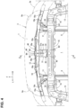
- an area LR enclosed by an imaginary line in FIG. 4 corresponds to a latch arrangement point.
- each front portion of the right-and-left front side frames 8 is located just below an end-outside portion of the shroud upper panel 15. Further, as shown in FIGS. 2 , 3 , 5 and 6 , the shroud member 16 and the front portion of the front side frame 8 are connected by a shroud-upper support frame 17 extending in a vertical direction.
- the shroud upper panel 15 is, as described above, supported by the pair of right-and-left apron reinforcements 13 via the shroud members 16 and supported by the pair of right-and-left front side frames 8 via the shroud members 16 and the shroud-upper support frames 17.
- the shroud-upper support frame 17 may be integrally formed by a vehicle-width-direction inner face portion 17a which is of a vertical wall shape and has its plate thickness in the vehicle width direction and a front face portion 17b which is of the vertical wall shape, extends outwardly, in the vehicle width direction, from a front end of the vehicle-width-direction inner face portion 17a, and has its plate thickness in the vehicle longitudinal direction.
- each of the apron reinforcement 13, the shroud upper panel 15, the front side frame 8, the shroud-upper support frame 17, the shroud member 16, and the bumper beam 12 is a vehicle-body member.
- the bumper-face support member 18 extends in the vehicle width direction having a shorter, particularly a slightly shorter extension length than the bumper beam 12 (see FIG. 4 ), and is arranged substantially at the same level as the shroud upper panel 15 at a position which nearly corresponds to the front portion of the bonnet 2 in the vehicle longitudinal direction, in other words, substantially at the same position as the bumper beam 12 in the vehicle longitudinal direction (see FIG. 6 ).
- the bumper-face attachment hole 18a may be comprised of one or plural holes which are arranged in the vehicle width direction at the bumper-face support member 18, and four holes are particularly provided at each side of the member 18 except the center, in total eight holes, in the present embodiment (see FIGS. 2 and 4 ).
- a face-upper support member 71 to support the bumper face upper 7 provided at the bumper face 3 from just below as shown in FIG. 6 .
- the face-upper support member 71 extends in the vehicle width direction so as to support the bumper face 3.
- the face-upper support member 71 may comprise primarily two members, an upper-side member 71a which has a nearly hat-shaped cross section opened downwardly and a lower-side member 71b which closes a downwardly-opened portion of the upper-side member 71a, and a closed-cross section 71c extending in the vehicle width direction is formed between the upper-side member 71a and the lower-side member 71b .
- a rear flange portion 71d which extends rearwardly so as to contact the bumper-face support member 18 from above may be formed at a rear end of a lower portion of the face-upper support member 71 (see FIGS. 6 and 8 ).
- the rear flange portion 71d extends in the vehicle width direction having substantially the same extension length as the bumper-face support member 18, and has bumper-face support member holes (not illustrated) at its plural points which correspond to the bumper-face attachment holes 18a.
- the bumper-face support member holes (not illustrated) and the bumper-face attachment holes 18a may be joined together by using fastening means, such as bolts and nuts (not illustrated) in a state where the rear flange portion 71d is supported by the bumper-face support member 18.
- fastening means such as bolts and nuts (not illustrated) in a state where the rear flange portion 71d is supported by the bumper-face support member 18.
- the bumper face 3 is supported by the bumper-face support member 18.
- a radiator shroud 10 is arranged in a front area of the power unit room 1 at a position behind the bumper-face support member 18.
- the radiator shroud 10 is supported at the vehicle-body member (e.g., the shroud upper panel 15, the front side frame 8 and the like).
- the radiator shroud 10 may be configured to be substantially rectangular, in an elevational view, and arranged in the front area of the power unit room 1 at a position between the front side frames 8, and supports the radiator 19 and others.
- the radiator shroud 10 and the radiator 19 are provided to stand and face the front-face opening 4 from behind, respectively.
- brackets 20, 30 which fixedly connect the vehicle-body member 15, 17 and the bumper-face support member 18 and a stay 40 which connects the bumper-face support member 18 and the bumper beam 12 in the vertical direction at the front portion of the vehicle body.
- the brackets 20, 30 may comprise the outside brackets 20 which are arranged at both outsides, in the vehicle width direction, of the vehicle body and/or the center bracket 30 which is arranged at the middle, in the vehicle width direction, of the vehicle body (i.e., the position corresponding to the stay 40 in the vehicle width direction). Thus, there are three brackets in total.
- the outside brackets 20 are configured to be laterally symmetrical, and each of these comprises a side wall portion 21 which extends in the vertical direction and in the vehicle longitudinal direction and an eaves-shaped flange portion 22 which protrudes inwardly, in the vehicle width direction, from an upper end of the side wall portion 21 via a corner portion 23, which is made of a metal plate which is bent through pressing process or the like.
- the outside bracket 20 comprises a fixation portion 24 for fixation to the shroud-upper support frame 17 as a vehicle-body member, a base portion 25 which extends forwardly from the fixation portion 24, and an inclination portion 26 which is inclined relative to the base portion 25.
- the outside bracket 20 may comprise high-rigidity portions 63U, 63D and fragile portions 62, 61f, 61r. At least part of each of the high-rigidity portions 63U, 63D is positioned at the inclination portion 26, and each of the high-rigidity portions 63U, 63D is configured to have the high rigidity (or the higher rigidity) against an input of a load applied in the vehicle longitudinal direction. Each of the fragile portions 62, 61f, 61r is configured to be deformable by receiving the input of the load applied in the vehicle longitudinal direction.
- the high-rigidity portions 63U, 63D and the fragile portions 62, 61f, 61r are provided adjacently to each other in the vehicle longitudinal direction.
- the middle bracket 30 may comprise a bracket body portion 31 which extends straightly in the vehicle longitudinal direction, in a vehicle plane view, between the stay 40 and the shroud upper panel 15 and a front flange portion 32 and a rear flange portion 33, which are formed integrally.
- the middle bracket 30 is made of a plate member extending in the vehicle longitudinal direction and in the vehicle width direction which is bent through pressing process or the like.
- the bracket body portion 31 may be arranged to be inclined or slightly inclined relative to a horizontal line such that its front side is located at a lower level, and the bracket body portion 31 may extend straightly in the vehicle longitudinal direction such that its front end is located slightly above an upper end of the stay 40 and its rear end is located at a lower end of a lower flange portion 15a which extends downwardly from a front end of the shroud upper panel 15.
- a striker of a safety lock device may be provided to stand upwardly at an upper face portion 31a of the bracket body portion 31.
- an engaging lever 55 of the safety lock device may be provided at a front central portion of the bonnet 2 so as to engage with or disengage from a striker 34.
- the safety lock device is a known device which is configured to restrain an opening move of the bonnet 2 even if a lock of a lock device (not illustrated) is released unexpectedly, thereby keeping a slightly-opened state of the bonnet 2, in order that the bonnet 2 is prevented from opening improperly because of a traveling-air pressure or the like during vehicle traveling.
- the safety lock device is arranged at a different position from the lock device (see the area LR enclosed by the imaginary line in FIG. 4 ) as described above (see FIG. 4 ).
- the front flange portion 32 extends downwardly from a front end of the bracket body portion 31, and the bracket body portion 31 extends forwardly from a vehicle rearward side such that its front portion straddles an upper end of the stay 40 from above. Thereby, the front flange portion 32 contacts an upper portion of the stay 40 (an upper portion of an upper flange portion 41 described later) from a vehicle forward side.
- the front flange portion 32 may be configured to have the nearly same length, in the vehicle width direction, as the upper flange portion 41 (see FIG. 5 ). Accordingly, the front flange portion 32 and the upper flange portion 41 may be provided to contact each other over a whole length, in the vehicle width direction, thereof.
- the upper flange portion 41 and the front flange portion 32 may be joined together by spot welding.
- the upper flange portion 41 and the front flange portion 32 are spot-welded at, in total, three points of a central point Sa and both-side points Sb, Sc .
- An "X" mark in FIG. 5 shows a spot-welding application point. That is, the joint points (Sa, Sb, Sc) of the middle bracket 30 and the stay 40 are located at an upper level than (i.e., above) a first bending portion 43 which will be described later as a deformation promotion of the stay 40.
- the rear flange portion 33 extends upwardly from a rear end of the bracket body portion 31, and contacts the lower flange portion 15a of the shroud upper panel 15 from the vehicle forward side.
- the rear flange portion 33 of the middle bracket 30 and the lower flange portion 15a of the shroud upper panel 15 are fastened together by a bolt B2 and a nut N2 as fastening means (see FIG. 6 ).
- the middle bracket 30 connects the shroud upper panel 15 and the stay 40.
- the stay 40 connects the bumper-face support member 18 and the bumper beam 12 in the vertical direction particularly at the nearly center, in the vehicle width direction, of the vehicle body at the front side of the power-unit room 1. Thereby, the bumper-face support member 18 is supported at the bumper beam 12 via the stay 40.
- the stay 40 is made of a meal member which has a width in the vehicle width direction and is long in the vertical direction.
- the stay 40 may comprise the upper flange portion 41, a first extension portion 42 which straightly extends downwardly from a lower end of the upper flange portion 41 in the vertical direction, a second extension portion 44 which straightly extends from a lower end of the first extension portion 42 via the first bending portion 43 in an inclined shape such that its lower side is located on the vehicle forward side, and a lower flange portion 46 which extends downwardly from a lower end of the second extension portion 44 via a second bending portion 45.
- the above-described first bending portion 43 is a deformation promotion portion which is configured to be bent when a collision load applied downwardly is inputted to the bumper-face support member 18, and this first bending portion 43 of the present embodiment is configured such that an angle between the first extension portion 42 and the second extension portion 44 becomes about 150 degrees, for example.
- the upper flange portion 41 and the lower flange portion 46 are configured to be longer or slightly longer than a middle part, in the vertical direction, of the stay 40 (i.e., the first extension portion 42 and the second extension portion 44) in the vehicle width direction.
- a lower part of the upper flange portion 41 may be configured such that its width becomes wider or gradually wider from the upper end of the first extension portion 42 toward the upper side.
- An upper part of the lower flange portion 46 may be configured such that its width becomes wider or gradually wider from the lower end of the second extension portion 44 toward the lower side.
- the stay 40 may be configured such that its cross section perpendicular to the vertical direction (its extension direction) is nearly horizontal in the vehicle width direction over its whole length. However, as shown in FIGS. 5 - 7 , the stay 40 may have a step portion 143 extending in the vehicle longitudinal direction at a position between its outward-side portion 141 and its central-side portion 142 such that the outward-side portion 141 is located on the vehicle rearward side of the central-side portion 142.
- the step portion 143 continuously extends in the vertical direction at a part of the stay 40 except an upper part of the upper flange portion 41 (see FIG. 5 ).
- a stay-reinforcing ridgeline 144 is formed at a corner portion between the step portion 143 and the central-side portion 142
- a stay-reinforcing ridgeline 145 is formed at a corner portion between the step portion 143 and the outward-side portion 141.
- These stay-reinforcing ridgelines 144 , 145 extend continuously in the extension direction of the stay 40 (in the vertical direction), including the first bending portion 43 and the second bending portion 45.
- the lower flange portion 46 may be fixed to a central portion, in the vehicle width direction, of the bumper beam 12 by a bolt B3 and a nut N3 in a state where it contacts an upper part of the closing plate portion 12b from behind.
- an engaging hook 48 which protrudes forwardly and has its tip projecting downwardly may be formed at a base portion (upper portion) of the lower flange portion 46.
- the engaging hook 48 engages with an upper end of the closing plate portion 12b at the bumper beam 12 in a state where the lower flange portion 46 contacts the upper part of the closing plate portion 12b from behind as described above.
- the stay 40 is connected to the bumper-face support member 18 via a gusset 50.
- the gusset 50 may comprise a lateral plate portion 51 which extends horizontally in the vehicle longitudinal direction and supports a lower side of the bumper-face support member 18 and a vertical plate portion 52 which extends downwardly from a rear end of the lateral plate portion 51, which is made of a metal plate extending in an inverse-L shape in a vehicle side view and has its width in the vehicle width direction.
- the gusset 50 may be located at the central portion, in the vehicle width direction, of the bumper-face support member 18, and the bumper-face support member 18 and the lateral plate portion 51 located just below the bumper-face support member 18 are fixedly fastened by fastening means (a bolt B4 and a nut N4). That is, the bumper-face support member 18 is supported by the lateral plate portion 51 extending forwardly from an upper end of the vertical plate portion 52 in a cantilever shape at a position located in front of the vertical plate portion 52.
- fastening means a bolt B4 and a nut N4
- the gusset 50 may be configured such that it has the same width over its whole length in the its extension direction and it has substantially the same length as the central-side portion 142 of the stay 40 in the vehicle width direction.
- a bending portion 151 which is configured to be bent in such a manner that it stands toward one direction in the plate-thick direction over its whole length in the extension direction is formed at each of both-side potions, in the vehicle width direction, of the gusset 50.
- the bending portion 151 is configured such that it is bent downwardly at the lateral plate portion 51 and it is bent forwardly at the vertical plate portion 52, and the bending portion 151 is formed continuously along its extension direction.
- the gusset-reinforcing ridgeline 153 which extending continuously over the whole length of the gusset 50 (the vertical plate portion 52 and the lateral plate portion 51 ) may be formed at a base end portion of the bending portion 151 (a border portion between the bending portion 151 and a flat-plate shaped vehicle-width-direction central portion) (see FIG. 7 ).
- the vertical plate portion 52 may be fixed to a point of the stay 40 which is located above the first bending portion 43, i.e., the upper flange portion 41.
- the vertical plate portion 52 may be made to contact the central-side portion 142 of the upper flange portion 41 from the vehicle forward side, and in this state, this portion 52 is fastened to the base portion (lower portion) of the upper flange portion 41 by fastening means (a bolt B5 and a nut N5) (see a major enlarged part in FIG. 6 and FIG. 7 ).
- the front flange portion 32 of the middle bracket 30 may be made to contact a tip portion (upper portion) of the upper flange portion 41 over a whole length, in the vehicle width direction, of the upper flange portion 41 from the vehicle forward side.
- deference character 54 in the major enlarged part in FIGS. 5 and 6 denotes an opening portion which is formed at a portion of the vertical plate portion 52 which covers the above-described spot-welding point (the spot-welding point Sb at the central portion in the vehicle width direction) from the vehicle forward side in order to allow the spot welding applied to the upper flange portion 41 and the front flange portion 32.
- the vertical plate portion 52 of the gusset 50 may be fixed to the stay 40 such that the lateral plate portion 51 extends forwardly from an upper end of the vertical plate portion 52 which extends upwardly from the upper end of the stay 40 and the middle bracket 30. Therefore, the gusset 50 is attached to the stay 40 such that the lateral plate portion 51 is located above the attachment position of the middle bracket 30 to the stay 40.
- the stay-reinforcing ridgeline 144 and the gusset-reinforcing ridgeline 153 may be located at the same position in the vehicle width direction in a state where the vertical plate portion 52 is fixed to the stay 40.
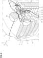
- FIG. 8 is a perspective sectional view taken along line A-A in FIG. 4 , which shows a situation just before the collision object 100 hits against the vehicle front portion
- FIG. 9 is a perspective sectional view similar to FIG. 8 , which shows results of a simulation analysis of the move of the vehicle front portion just after the hitting of the collision object 100.
- FIG. 9 shows a distribution of stresses of the collision load inputted to the stay 40 is shown based on dots density, wherein a portion with a higher density of dots shows an area where a larger bending-stress is generated.
- the collision load inputted to the upper flange portion 41 of the stay 40 is transmitted further downwardly, i.e., to the first bending portion 43 as the deformation promotion portion via the first extension portion 42, where the stress focus as shown in FIG. 9 .
- the stay 40 can be securely deformed at the first bending portion 43 without being stretched against the downward collision load.
- the front structure of the vehicle of the above-described resent invention comprises, as shown in FIGS. 2 - 6 , the vehicle-body member (15, 17) provided at the vehicle-body front portion, the bumper-face support member 18 (see FIGS. 1 - 4 and 6) extending in the vehicle width direction in front of the vehicle-body member (15, 17) and having the bumper-face attachment hole 18a (attachment portion) where the bumper face 3 (see FIG.
- the plural brackets 20, 30 (the outside bracket 20 and the middle bracket 30) fixedly connecting the vehicle-body member (15, 17) and the bumper-face support member 18, the bumper beam 12 extending in the vehicle width direction below the bumper-face support member 18, and the stay 40 connecting the bumper-face support member 18 and the bumper beam 12 in the vertical direction, wherein the stay 40 has the deformation promotion portion (the first bending portion 43) configured to be bent so as to promote deformation of the stay 40 when the collision load is downwardly inputted to the bumper-face support member 18 as shown in FIGS. 5 and 6 .
- the support rigidity and the assembling accuracy of the bumper face 3 in the normal state and the pedestrian's protection performance in the vehicle frontal collision can be compatibly improved even if the vehicle has the high vehicle-height.
- the downward load is inputted to the bumper-face support member 18 even in the normal state because of each weight of the bumper face 3 and the bumper-face support member 18, a pressing-down force by a person's hand applied to the bonnet 2 for closing the bonnet 2, or the like.
- the front end portion of the bonnet is generally located at the level of the pedestrian's thigh portion in the vehicle having the high vehicle-height, there exists a structure in which the front end portion of the bonnet is retreated from a foremost portion of the vehicle in order to reduce an influence on a knee's ligament of the pedestrian in the vehicle collision like the vehicle of the present invention (see FIG. 6 ).
- this vehicle is configured such that the vehicle-body member, such as the shroud member 16 or the shroud upper panel 15 which are provided with the latch as a lock device of the bonnet 2, is retreated together width the bonnet's front end portion.
- the vehicle-body member such as the shroud member 16 or the shroud upper panel 15 which are provided with the latch as a lock device of the bonnet 2
- the length, in the vehicle longitudinal length, between the bumper-face support member 18 supporting the bumper face 3 and the vehicle-body member (15, 17), such as the shroud upper panel 15 supporting the bumper-face support member 18 in the cantilever shape from behind becomes long. Therefore, in particular, in the vehicle having the high vehicle-height, when the above-described downward load is inputted to the bumper-face support member 18, there is a concern that a load applied to the brackets 20, 30 connecting the bumper-face support member 18 and the vehicle-body member (15, 17) in the vehicle longitudinal direction may become improperly large.
- the stay 40 is stretched against the downward load inputted to the bumper-face support member 18 in the normal state as described above, so that the bumper-face support member 18 is suppressed from being deformed downwardly. Consequently, the support rigidity and the assembling accuracy of the bumper face 3 in the normal state can be improved.
- the deformation promotion portion (the first bending portion 43) of the stay 40 is bent and deformed in a case where the downward collision load is inputted to the bumper-face support member 18, the damage degree of the collision object can be reduced, so that the pedestrian's protection performance in the vehicle collision can be improved.
- the support rigidity and the assembling accuracy of the bumper face 3 in the normal state and the pedestrian's protection performance in the vehicle frontal collision can be compatibly improved even if the vehicle has the high vehicle-height.
- the bracket (20, 30) comprises the middle bracket 30 (indirect bracket) to fixedly connect the shroud upper panel 15 as the vehicle-body member and the bumper-face support member 18 via the stay 40, and the middle bracket 30 is configured to fixedly connect the shroud upper panel 15 and the stay 40 therebetween.
- the stay 40 can support the bumper-face support member 18 in a state where the stay 40 is supported by the middle bracket 3, the support rigidity and the assembling accuracy of the bumper face 3 in the normal state can be further improved.
- the stay 40 comprises the first extension portion 42 extending downwardly and the second extension portion 44 extending obliquely downwardly-and-forwardly from the lower end of the first extension portion 42 via the first bending portion 43 (bending portion) as the deformation promotion portion.
- the stay 40 can be bent and deformed securely by making the first bending portion 43 be a bending causing point, and the deformation promotion portion can be constituted with a simple structure in which a part of the stay 40 is formed in a bending shape.
- the stay 40 is connected to the bumper-face support member 18 (see FIGS. 4 and 6 ) via the gusset 50, and the gusset 50 comprises the lateral plate portion 51 extending in the vehicle longitudinal direction and supporting the bumper-face support member 18 and the vertical plate portion 52 downwardly extending from the lateral plate portion 51 and fixed to a point of the stay 40 which is located above the first bending portion 43.
- this collision load when the downward collision load is inputted to the bumper-face support member 18, this collision load can be firmly received by the lateral plate portion 51 and also efficiently transmitted to the lower-located first bending portion 43 of the stay 40 via the vertical plate portion 52.
- the stay 40 can be prevented from being improperly deformed at any other point than the first bending portion 43, which may be caused by some unexpected bending moment applied to the stay 40 during the above-described load's transmission to the stay 40 from the bumper-face support member 18.
- the stay 40 can be securely deformed at a target point (i.e., the first bending promotion portion 43).
- the assembling level (height) of the bumper-face support member 18 can be adjusted precisely and easily by using the gusset 50 differently from a case where the stay 40 is directly connected to the bumper-face support member 18.
- the vertical plate portion 52 extends downwardly from the rear end of the lateral plate portion 51, and the lateral plate portion 51 supports the bumper-face support member 18 (see FIGS. 4 and 6 ) in front of the vertical plate portion 52.
- the lateral plate portion 51 is configured to support the bumper-face support member 18 from the forward side of the vertical plate portion 52.
- the bumper-face support member 18 can be supported by the lateral plate portion 51 at a properly front-side vehicle's end position without arranging the stay 40 itself at the forward position, and the length, in the vehicle longitudinal direction, of the middle bracket 30 can be made as short as possible.
- the length, in the vehicle longitudinal direction, of the middle bracket 30 can be suppressed, allowing a situation where the distance, in the vehicle longitudinal direction, between the bumper face 3 and the shroud upper panel 15 becomes long according to the retreat of the front end 2f of the bonnet 2 , so that the support rigidity and the assembling accuracy of the bumper face 3 in the normal state can be further improved.
- the front flange portion 32 (front end) of the middle bracket 30 extending in the vehicle longitudinal direction is attached to the point of the stay 40 which is located above the first bending portion 43 in the vertical direction.
- the support rigidity and the assembling accuracy of the bumper face 3 in the normal state can be improved. Further, when the downward collision load is inputted to the bumper-face support member 18, it can be extremely suppressed that an auxiliary component, such as the radiator 19, is damaged by the stay.
- the bumper-face support member 18 when the downward collision load is inputted to the bumper-face support member 18, a bending stress to make the first extension portion 42 (the portion located above the first bending portion 43 ) of the stay 40 be bent forwardly (lean forwardly) together with the lateral plate portion 51 is applied to the first bending portion 43.
- the stay 40 tends to be bent easily by the downward load input even in the normal state at the first bending portion 43, which is not preferable.
- the first extension portion 42 of the stay 40 is bent forwardly (leans forwardly)
- the first bending portion 43 is bent such that it protrudes rearwardly, so that the auxiliary component, such as the radiator 19, may be damaged by the stay 40, which is not preferable either.
- the front flange portion 32 of the middle bracket 30 extending in the vehicle longitudinal direction is attached to the point of the stay 40 which is located above the first bending portion 43, it can be suppressed that the upper portion of the stay 40 is unexpectedly deformed in a forwardly-leaning shape when the downward load is inputted to the bumper-face support member 18 in the normal state, so that the support rigidity and the assembling accuracy of the bumper face 3 in the normal state can be improved.
- the stay 40 can be securely deformed at the first bending portion 43 without making the upper portion of the stay 40 be deformed in the forwardly-leaning shape when the downward load is inputted to the bumper-face support member 18 in the normal state, the auxiliary component, such as the radiator 19, can be suppressed from being damaged as much as possible.
- the attachment position of the middle bracket 30 to the stay 40 is located below the lateral plate portion 15.
- the upper portion of the stay 40 can be supported by the middle bracket 30 at a lower position which is closer to the first bending portion 43 than the lateral plate portion 51 so that it can be prevented that the first bending portion 43 as the deformation promotion portion of the stay 40 is bent and thereby the first bending portion 43 moves toward a side of the auxiliary component, such as the radiator 19 (rearwardly) in a vehicle light collision.
- a lower end of the first extension portion 42 is prevented from protruding downwardly in the vehicle light collision, so that it can be suppressed that the auxiliary component, such as the radiator 19, is damaged by the stay 40.
- the stay 40 has the stay-reinforcing ridgelines 144, 145 which extends in the extension direction of the stay 40, continuously over a range of the first bending portion 43 and the gusset-reinforcing ridgeline 153 which extends, in the extension direction of the gusset 50, continuously over a range of the vertical plate portion 52 and the lateral plate portion 51, and the stay-reinforcing ridgeline 144 and the gusset-reinforcing ridgeline 153 are located substantially at the same position in the vehicle width direction in a state where the vertical plate portion 52 is fixed to the stay 40 as shown in FIG. 7 .
- the stay 40 is prevented by the stay-reinforcing ridgelines 144, 145 from being deformed unexpectedly at the first bending portion 43 by the downward load in the normal state, so that the bending rigidity can be properly secured.
- this load can be efficiently transmitted to the lateral plate 51, the vertical plate portion 52, and the stay 40 in order along the ridgelines (153,144). That is, when the downward collision load is inputted to the bumper-face support member 18, the impact load is efficiently transmitted between different members, such as from the lateral plate portion 51 to the vertical plate portion 52, or from the vertical plate portion 52 to the stay 40, so that the stay 40 can be securely deformed at the first bending portion 43.
- the present invention is not limited to the above-described embodiment, but can be materialized by various modifications.
Abstract
Description
- The present invention relates to a front structure of a vehicle which comprises a bumper face provided at a vehicle front portion and a vehicle-body member supporting the bumper face from behind at a vehicle-body front portion.
-
Japanese Patent Laid-Open Publication No. 2015-196443 - As disclosed in the above-described patent document, a structure in which the bumper face is supported in a cantilever shape by the vehicle-body member, such as the shroud upper provided at the vehicle-body front portion is known.
- Meanwhile, vehicles having a high vehicle-height are generally configured such that a front end portion of a bonnet (engine hood) provided at a front upper end of the vehicle is located at the same level as a thigh portion of a pedestrian. Accordingly, a structure in which the front end portion of the bonnet is retreated from a foremost portion of the vehicle so as to meet the pedestrian protection requirement, such as reduction of an influence on a knee's ligament of the pedestrian, in a vehicle collision against the pedestrian is known among the vehicles having the high vehicle-height.
- Further, a latch which is configured to engage with a striker protruding downwardly from the bonnet in a bonnet's closed state and lock the bonnet is generally provided at the vehicle-body member, such as the shroud upper. Therefore, many of the vehicles having the high vehicle-height tend to have a structure in which the vehicle-body member, such as the shroud upper, is also retreated together with the bonnet according to the above-described retreat of the front end portion of the bonnet.
- In this structure, however, since a length, in a vehicle longitudinal direction, between the bumper face and the vehicle-body member, such as the shroud upper supporting the bumper face in the cantilever shape from behind, becomes improperly long, a burden applied to a bracket which connects the bumper face and the vehicle-body member in the vehicle longitudinal direction becomes large, so that there is a concern that the support rigidity and the assembling accuracy of the bumper face may deteriorate.
- For this problem, it may be considered that the bumper face is supported by a bumper beam provided just below the bumper face or the like from below via a stay.
- In the vehicle collision against the pedestrian, it has been conventionally tried to sweep pedestrian's legs and make an pedestrian's upper body fall down onto the bonnet for the protection of a pedestrian's head portion, expecting the damping effect by the bonnet. However, since a collision area where the pedestrian's head portion hits against the bonnet moves forwardly more as the vehicle-height of the vehicle becomes higher, if the front portion of the bonnet becomes harder because the stay supporting the bumper face from just below is provided as described above, there occurs a new problem that the pedestrian's protection performance may deteriorate.
- The present invention has been devised in view of the above-described problems, and an object of the present invention is to provide a front structure of a vehicle which can compatibly improve the support rigidity and the assembling accuracy of the bumper face in a normal state and the pedestrian's protection performance in a vehicle frontal collision even if the vehicle has the high vehicle-height.
- The front structure of the vehicle of the present invention comprises a vehicle-body member provided at a vehicle-body front portion, a bumper-face support member extending in a vehicle width direction in front of the vehicle-body member and having an attachment portion where a bumper face is attached, plural brackets fixedly connecting the vehicle-body member and the bumper-face support member, a bumper beam extending in the vehicle width direction below the bumper-face support member, and a stay connecting the bumper-face support member and the bumper beam in a vertical direction, wherein the stay has a deformation promotion portion configured to be bent so as to promote deformation of the stay when a collision load is downwardly inputted to the bumper-face support member.
- According to the present invention, since the stay is stretched against the downward load inputted to the bumper-face support member in the normal state, the bumper-face support member is suppressed from being deformed downwardly, so that the support rigidity and the assembling accuracy of the bumper face in the normal state can be improved. Meanwhile, since the deformation promotion portion is bent and deformed in a case where the downward collision load is inputted to the bumper-face support member, the damage degree of a collision object can be reduced, so that the pedestrian's protection performance in the vehicle frontal collision can be improved.
- In an embodiment of the present invention, the bracket may comprise an indirect bracket to fixedly connect a shroud upper as the vehicle-body member and the bumper-face support member via the stay, and the indirect bracket may be configured to fixedly connect the shroud upper and the stay therebetween.
- According to this embodiment, since the stay can support the bumper-face support member in a state where the stay is supported by the indirect bracket, the support rigidity and the assembling accuracy of the bumper face in the normal state can be further improved.
- In another embodiment of the present invention, the stay may comprise a first extension portion extending downwardly and a second extension portion extending obliquely downwardly-and-forwardly from a lower end of the first extension portion via a bending portion as the deformation promotion portion.
- According to this embodiment, since when the downward collision load is inputted to the bumper-face support member, the load transmitted to the stay from the bumper-face support member focuses on the bending portion, the stay can be bent and deformed securely by making the bending portion be a bending causing point, and the deformation promotion portion can be constituted with a simple structure in which a part of the stay is formed in a bending shape.
- In another embodiment of the present invention, the stay may be connected to the bumper-face support member via a gusset, and the gusset may comprise a lateral plate portion extending in a vehicle longitudinal direction and supporting the bumper-face support member and a vertical plate portion downwardly extending from the lateral plate portion and fixed to a point of the stay which is located above the deformation promotion portion.
- According to this embodiment, when the downward collision load is inputted to the bumper-face support member, this collision load can be firmly received by the lateral plate portion and also efficiently transmitted to the lower-located deformation promotion portion of the stay via the vertical plate portion.
- That is, the stay can be prevented from being improperly deformed at any other point than the deformation promotion portion, which may be caused by some unexpected bending moment applied to the stay during the above-described load's transmission to the stay from the bumper-face support member. Thus, the stay can be securely deformed at a target point (i.e., the deformation promotion portion).
- In another embodiment of the present invention, the vertical plate portion may extend downwardly from a rear end of the lateral plate portion, and the lateral plate portion may support the bumper-face support member in front of the vertical plate portion.
- According to this embodiment, since the vertical plate portion extends downwardly from the rear end of the lateral plate portion, the lateral plate portion is configured to support the bumper-face support member from a forward side of the vertical plate portion. Thereby, the bumper-face support member can be supported by the lateral plate portion at a properly front-side vehicle's end position without arranging the stay itself at the forward position.
- Accordingly, the length, in the vehicle longitudinal direction, of the indirect bracket can be properly suppressed, allowing a situation where the distance, in the vehicle longitudinal direction, between the bumper-face support member (bumper face) and the shroud upper becomes long according to the retreat of the front end of the bonnet, so that the support rigidity and the assembling accuracy of the bumper face in the normal state can be improved.
- In another embodiment of the present invention, a front end of the indirect bracket extending in the vehicle longitudinal direction may be attached to a point of the stay which is located above the deformation promotion portion in the vertical direction.
- According to this embodiment, even in the structure in which the bumper-face support member is arranged in front of the vehicle-body member, the support rigidity and the assembling accuracy of the bumper face in the normal state can be improved.
- In another embodiment of the present invention, an attachment position of the indirect bracket to the stay may be located below the lateral plate portion.
- According to this embodiment, an upper portion of the stay can be supported by the indirect bracket at a lower position which is closer to the deformation promotion portion than the lateral plate portion. Thereby, a lower end of the upper portion (first extension portion) is prevented from protruding downwardly when the stay is bent at the deformation promotion portion in a vehicle light collision, so that it can be suppressed that an auxiliary component, such as a radiator, is damaged by the stay.
- In another embodiment of the present invention, the stay may have a stay-reinforcing ridgeline which extends, in an extension direction of the stay, continuously over a range of the deformation promotion portion and a gusset-reinforcing ridgeline which extends, in an extension direction of the gusset, continuously over a range of the vertical plate portion and the lateral plate portion, and the stay-reinforcing ridgeline and the gusset-reinforcing ridgeline may be located substantially at the same position in the vehicle width direction in a state where the vertical plate portion is fixed to the stay.
- According to this embodiment, since the stay-reinforcing ridgeline is formed at the stay, the stay is prevented from being deformed unexpectedly at the deformation promotion portion by a load applied from below in the normal state, so that the bending rigidity can be secured.
- Further, when the downward collision load is inputted to the bumper-face support member, this load can be efficiently transmitted to the lateral plate, the vertical plate portion, and the stay in order along the gusset-reinforcing ridgeline and the stay-reinforcing ridgeline. Accordingly, the stay can be securely deformed at the deformation promotion portion when the downward collision load is inputted to the bumper-face support member.
- As described above, according to the present invention, the support rigidity and the assembling accuracy of the bumper face in the normal state and the pedestrian's protection performance in the vehicle frontal collision can be compatibly improved even if the vehicle has the high vehicle-height.
- The present invention will become apparent from the following description which refers to the accompanying drawings.
-
-
FIG. 1 is an exterior perspective view of a front portion of a vehicle of the present embodiment. -
FIG. 2 is a perspective view of the front portion of the vehicle of the present embodiment. -
FIG. 3 is an enlarged perspective view of the front portion of the vehicle, when viewed from a further front side inFIG. 2 . -
FIG. 4 is a plan view showing a major part of the front portion of the vehicle of the present embodiment. -
FIG. 5 is an enlarged perspective view of a central part, in a vehicle width direction, of the front portion of the vehicle in a state where a bumper-face support member is removed inFIG. 3 . -
FIG. 6 is a sectional view taken along line A-A inFIG. 4 . -
FIG. 7 is an enlarged sectional view taken along line B-B inFIG. 5 . -
FIG. 8 is a perspective sectional view taken along line A-A inFIG. 4 , which shows a situation just before a collision object hits against a front end of a bonnet from above. -
FIG. 9 is a perspective sectional view similar toFIG. 8 , which shows a distribution of stresses applied to a stay just after the collision object hits against the front end of the bonnet from above. - Hereafter, an embodiment of the present invention will be described referring to the drawings. All of the features as shown in the drawing may not necessary be essential. In the drawings, an arrow F shows a vehicle forward side, an arrow U shows a vehicle upward side, an arrow R shows a vehicle rightward side, and an arrow L shows a vehicle leftward side.
- A vehicle to which a front structure of the present invention is applied is an automobile, such as Sports Utility Vehicle (SUV) or minivan, which has a relatively high vehicle-height compared with a sedan type or a hutch-back type. The front structure of the vehicle of the present embodiment may be configured to be substantially symmetrical laterally.
- As shown in
FIG. 1 , a front portion of the vehicle is provided with abonnet 2 which covers over a power-unit room (or a power-unit compartment) 1 (seeFIG. 2 ) where a power unit (not illustrated), such as an engine, is installed and abumper face 3 which is made of synthetic resin and arranged at a foremost position of the vehicle. A front-face openingportion 4 to take in flesh air (traveling air) into a vehicle body may be formed at thebumper face 3. - The front-
face opening portion 4 may be formed at a portion of thebumper face 3 which is located at an upper-and-central side, in a vehicle width direction, of thebumper face 3, which is an outside-air induction port to introduce outside air for cooling into the power-unit room 1 in order to assist heat radiation of a radiator 19 (seeFIG. 8 ) which is arranged at a front side of the power-unit room 1 located and in back of thebumper face 3. - The front-
face opening port 4 may be covered with afront grille 5 in a state where the air permeability of the power-unit room 1 is secured. A pair ofheadlight opening portions 6 for arrangingheadlamps 6a (seeFIG. 4 ) are formed at right-and-left upper portions of thebumper face 3. - The
front grille 5 may extend laterally up to an inside portion, in the vehicle width direction, of each of theheadlight opening portions 6 at a position which corresponds, in a front view, to the front-face opening portion 4 provided at a central portion, in the vehicle width direction, of thebumper face 3, and may be attached to thebumper face 3. - At an upper-end side of the
bumper face 3 is provided a bumper face upper 7 which constitutes an upper end portion of thebumper face 3 and is continuous to afront end 2f of thebonnet 2. The bumper face upper 7 is a portion which is integrally formed at abody portion 3a (lower portion) of thebumper face 3, which forms respective upper-side parts of the front-face openingportion 4 and the right-and-leftheadlight opening portions 6. The bumper face upper 7 is a flat-plate member with an upper face which has an inclination corresponding to a front-lowering inclination of an upper face of thebonnet 2. - The
bonnet 2 is pivotally supported at the vehicle body via a hinge (not illustrated) through its rear end so that it is openable over the power-unit room 1. - As shown in
FIG. 6 , thebonnet 2 may be comprised of a bonnetouter panel 2a and a bonnetinner panel 2b which may be integrated by means of hemming joint, and a bonnet reinforcement, not illustrated, may be adhesively fixed to a lower-face side of the bonnetouter panel 2a. - Herein, at a front portion of a central portion, in the vehicle width direction, of the bonnet
inner panel 2b is provided a striker (not illustrated) which protrudes downwardly. This striker is configured to engage with a latch (not illustrated) provided at a vehicle-body side in a closed state of thebonnet 2 for locking. - As shown in
FIGS. 2 - 4 , afront side frame 8 extending in a vehicle longitudinal direction is provided at each of right-and-left both sides of the power-unit room 1. A crash can 11 extending forwardly is attached to a front end of thefront side frame 8 via a set plate 9 (seeFIGS. 2 and3 ). - As shown in
FIGS. 2 - 4 , a bumper beam 12 (bumper reinforcement) which extends in the vehicle width direction so as to interconnect respective front ends of the right-and-leftcrash cans 11 may be provided at a front-side position of thepower unit room 1 which is located below and behind thebumper face 3. - As shown in
FIGS. 2 and3 , thebumper beam 12 is primarily composed of a bumper-beam body portion 12a which has a nearly hat-shaped cross section opened forwardly and aclosing plate portion 12b which closes a forwardly-opened portion of the bumper-beam body portion 12a, and a closed-cross section 12c extending in the vehicle width direction is formed between the bumper-beam body portion 12a and theclosing plate portion 12b. As shown inFIG. 6 , thebumper beam 12 is positioned at thefront end 2f of thebonnet 2 in the vehicle longitudinal direction. - Further, a pair of right-and-left
apron reinforcements 13 extending in the vehicle longitudinal direction are provided at upward-side positions inside the vehicle front portion which are located on the outward side, in the vehicle width direction, of thefront side fames 8. Herein, inFIGS. 2 and3 ,reference character 14 denotes a fender panel which forms an outside face of a vehicle-body front portion, which is supported at theapron reinforcement 13. - As shown in
FIGS. 2 - 4 , a shroudupper panel 15 extending straightly in the vehicle width direction may be connected to each front end of the pair of right-and-leftapron reinforcements 13 via ashroud member 16. - An engaging latch (not illustrated) to engage with a striker (not illustrated) provided at a side of the
bonnet 2 as a lock device may be arranged at the above-describedshroud member 16. Herein, an area LR enclosed by an imaginary line inFIG. 4 corresponds to a latch arrangement point. - As shown in
FIG. 4 , each front portion of the right-and-left front side frames 8 is located just below an end-outside portion of the shroudupper panel 15. Further, as shown inFIGS. 2 ,3 ,5 and6 , theshroud member 16 and the front portion of thefront side frame 8 are connected by a shroud-upper support frame 17 extending in a vertical direction. - That is, the shroud
upper panel 15 is, as described above, supported by the pair of right-and-leftapron reinforcements 13 via theshroud members 16 and supported by the pair of right-and-left front side frames 8 via theshroud members 16 and the shroud-upper support frames 17. - As shown in
FIGS. 2 ,3 ,5 and6 , the shroud-upper support frame 17 may be integrally formed by a vehicle-width-directioninner face portion 17a which is of a vertical wall shape and has its plate thickness in the vehicle width direction and afront face portion 17b which is of the vertical wall shape, extends outwardly, in the vehicle width direction, from a front end of the vehicle-width-directioninner face portion 17a, and has its plate thickness in the vehicle longitudinal direction. - Herein, each of the
apron reinforcement 13, the shroudupper panel 15, thefront side frame 8, the shroud-upper support frame 17, theshroud member 16, and thebumper beam 12 is a vehicle-body member. - Further, as shown in
FIGS. 2 - 4 , at a position inside the vehicle front portion which is located in front of the shroudupper panel 15 is arranged a bumper-face support member 18 with a bumper-face attachment hole 18a where the bumper face 3 (seeFIG. 1 ) is attached by a fastening means (bolt and nut), not illustrated. - The bumper-
face support member 18 extends in the vehicle width direction having a shorter, particularly a slightly shorter extension length than the bumper beam 12 (seeFIG. 4 ), and is arranged substantially at the same level as the shroudupper panel 15 at a position which nearly corresponds to the front portion of thebonnet 2 in the vehicle longitudinal direction, in other words, substantially at the same position as thebumper beam 12 in the vehicle longitudinal direction (seeFIG. 6 ). - The bumper-
face attachment hole 18a may be comprised of one or plural holes which are arranged in the vehicle width direction at the bumper-face support member 18, and four holes are particularly provided at each side of themember 18 except the center, in total eight holes, in the present embodiment (seeFIGS. 2 and4 ). - Meanwhile, inside the above-described
bumper face 3 is provided a face-upper support member 71 to support the bumper face upper 7 provided at thebumper face 3 from just below as shown inFIG. 6 . The face-upper support member 71 extends in the vehicle width direction so as to support thebumper face 3. - Further, as shown in
FIG. 6 , the face-upper support member 71 may comprise primarily two members, an upper-side member 71a which has a nearly hat-shaped cross section opened downwardly and a lower-side member 71b which closes a downwardly-opened portion of the upper-side member 71a, and a closed-cross section 71c extending in the vehicle width direction is formed between the upper-side member 71a and the lower-side member 71b. - A
rear flange portion 71d which extends rearwardly so as to contact the bumper-face support member 18 from above may be formed at a rear end of a lower portion of the face-upper support member 71 (seeFIGS. 6 and8 ). Therear flange portion 71d extends in the vehicle width direction having substantially the same extension length as the bumper-face support member 18, and has bumper-face support member holes (not illustrated) at its plural points which correspond to the bumper-face attachment holes 18a. - The bumper-face support member holes (not illustrated) and the bumper-
face attachment holes 18a may be joined together by using fastening means, such as bolts and nuts (not illustrated) in a state where therear flange portion 71d is supported by the bumper-face support member 18. Thus, thebumper face 3 is supported by the bumper-face support member 18. - Moreover, as shown in
FIG. 8 , aradiator shroud 10 is arranged in a front area of thepower unit room 1 at a position behind the bumper-face support member 18. Theradiator shroud 10 is supported at the vehicle-body member (e.g., the shroudupper panel 15, thefront side frame 8 and the like). - The
radiator shroud 10 may be configured to be substantially rectangular, in an elevational view, and arranged in the front area of thepower unit room 1 at a position between the front side frames 8, and supports theradiator 19 and others. Theradiator shroud 10 and theradiator 19 are provided to stand and face the front-face opening 4 from behind, respectively. - Further, as shown in
FIGS. 2 - 6 , at the front portion of the vehicle body are providedplural brackets body member face support member 18 and astay 40 which connects the bumper-face support member 18 and thebumper beam 12 in the vertical direction at the front portion of the vehicle body. - The
brackets outside brackets 20 which are arranged at both outsides, in the vehicle width direction, of the vehicle body and/or thecenter bracket 30 which is arranged at the middle, in the vehicle width direction, of the vehicle body (i.e., the position corresponding to thestay 40 in the vehicle width direction). Thus, there are three brackets in total. - As shown in
FIG. 5 , theoutside brackets 20 are configured to be laterally symmetrical, and each of these comprises aside wall portion 21 which extends in the vertical direction and in the vehicle longitudinal direction and an eaves-shapedflange portion 22 which protrudes inwardly, in the vehicle width direction, from an upper end of theside wall portion 21 via acorner portion 23, which is made of a metal plate which is bent through pressing process or the like. - In other words, the
outside bracket 20 comprises afixation portion 24 for fixation to the shroud-upper support frame 17 as a vehicle-body member, abase portion 25 which extends forwardly from thefixation portion 24, and aninclination portion 26 which is inclined relative to thebase portion 25. - The
outside bracket 20 may comprise high-rigidity portions fragile portions rigidity portions inclination portion 26, and each of the high-rigidity portions fragile portions rigidity portions fragile portions - As shown in
FIGS. 4 - 6 , themiddle bracket 30 may comprise abracket body portion 31 which extends straightly in the vehicle longitudinal direction, in a vehicle plane view, between thestay 40 and the shroudupper panel 15 and afront flange portion 32 and arear flange portion 33, which are formed integrally. In the present embodiment, themiddle bracket 30 is made of a plate member extending in the vehicle longitudinal direction and in the vehicle width direction which is bent through pressing process or the like. - As shown in
FIG. 6 , thebracket body portion 31 may be arranged to be inclined or slightly inclined relative to a horizontal line such that its front side is located at a lower level, and thebracket body portion 31 may extend straightly in the vehicle longitudinal direction such that its front end is located slightly above an upper end of thestay 40 and its rear end is located at a lower end of alower flange portion 15a which extends downwardly from a front end of the shroudupper panel 15. Herein, as shown inFIGS. 5 and6 , a striker of a safety lock device may be provided to stand upwardly at anupper face portion 31a of thebracket body portion 31. - Herein, an engaging
lever 55 of the safety lock device (seeFIG. 8 ) may be provided at a front central portion of thebonnet 2 so as to engage with or disengage from astriker 34. The safety lock device is a known device which is configured to restrain an opening move of thebonnet 2 even if a lock of a lock device (not illustrated) is released unexpectedly, thereby keeping a slightly-opened state of thebonnet 2, in order that thebonnet 2 is prevented from opening improperly because of a traveling-air pressure or the like during vehicle traveling. In the present embodiment, the safety lock device is arranged at a different position from the lock device (see the area LR enclosed by the imaginary line inFIG. 4 ) as described above (seeFIG. 4 ). - As shown in
FIGS. 5 and6 , thefront flange portion 32 extends downwardly from a front end of thebracket body portion 31, and thebracket body portion 31 extends forwardly from a vehicle rearward side such that its front portion straddles an upper end of thestay 40 from above. Thereby, thefront flange portion 32 contacts an upper portion of the stay 40 (an upper portion of anupper flange portion 41 described later) from a vehicle forward side. - The
front flange portion 32 may be configured to have the nearly same length, in the vehicle width direction, as the upper flange portion 41 (seeFIG. 5 ). Accordingly, thefront flange portion 32 and theupper flange portion 41 may be provided to contact each other over a whole length, in the vehicle width direction, thereof. - The
upper flange portion 41 and thefront flange portion 32 may be joined together by spot welding. In the present embodiment, theupper flange portion 41 and thefront flange portion 32 are spot-welded at, in total, three points of a central point Sa and both-side points Sb, Sc. An "X" mark inFIG. 5 shows a spot-welding application point. That is, the joint points (Sa, Sb, Sc) of themiddle bracket 30 and thestay 40 are located at an upper level than (i.e., above) afirst bending portion 43 which will be described later as a deformation promotion of thestay 40. - Meanwhile, the
rear flange portion 33 extends upwardly from a rear end of thebracket body portion 31, and contacts thelower flange portion 15a of the shroudupper panel 15 from the vehicle forward side. Therear flange portion 33 of themiddle bracket 30 and thelower flange portion 15a of the shroudupper panel 15 are fastened together by a bolt B2 and a nut N2 as fastening means (seeFIG. 6 ). - Thus, the
middle bracket 30 connects the shroudupper panel 15 and thestay 40. As shown inFIGS. 2 ,3 and6 , thestay 40 connects the bumper-face support member 18 and thebumper beam 12 in the vertical direction particularly at the nearly center, in the vehicle width direction, of the vehicle body at the front side of the power-unit room 1. Thereby, the bumper-face support member 18 is supported at thebumper beam 12 via thestay 40. - The
stay 40 is made of a meal member which has a width in the vehicle width direction and is long in the vertical direction. Specifically, as shown inFIGS. 5 and6 , thestay 40 may comprise theupper flange portion 41, afirst extension portion 42 which straightly extends downwardly from a lower end of theupper flange portion 41 in the vertical direction, asecond extension portion 44 which straightly extends from a lower end of thefirst extension portion 42 via thefirst bending portion 43 in an inclined shape such that its lower side is located on the vehicle forward side, and alower flange portion 46 which extends downwardly from a lower end of thesecond extension portion 44 via asecond bending portion 45. The above-described first bendingportion 43 is a deformation promotion portion which is configured to be bent when a collision load applied downwardly is inputted to the bumper-face support member 18, and this first bendingportion 43 of the present embodiment is configured such that an angle between thefirst extension portion 42 and thesecond extension portion 44 becomes about 150 degrees, for example. - The
upper flange portion 41 and thelower flange portion 46 are configured to be longer or slightly longer than a middle part, in the vertical direction, of the stay 40 (i.e., thefirst extension portion 42 and the second extension portion 44) in the vehicle width direction. - A lower part of the
upper flange portion 41 may be configured such that its width becomes wider or gradually wider from the upper end of thefirst extension portion 42 toward the upper side. An upper part of thelower flange portion 46 may be configured such that its width becomes wider or gradually wider from the lower end of thesecond extension portion 44 toward the lower side. - The
stay 40 may be configured such that its cross section perpendicular to the vertical direction (its extension direction) is nearly horizontal in the vehicle width direction over its whole length. However, as shown inFIGS. 5 - 7 , thestay 40 may have astep portion 143 extending in the vehicle longitudinal direction at a position between its outward-side portion 141 and its central-side portion 142 such that the outward-side portion 141 is located on the vehicle rearward side of the central-side portion 142. - The
step portion 143 continuously extends in the vertical direction at a part of thestay 40 except an upper part of the upper flange portion 41 (seeFIG. 5 ). Thereby, as shown inFIGS. 5 and7 , a stay-reinforcingridgeline 144 is formed at a corner portion between thestep portion 143 and the central-side portion 142, and a stay-reinforcingridgeline 145 is formed at a corner portion between thestep portion 143 and the outward-side portion 141. These stay-reinforcingridgelines first bending portion 43 and thesecond bending portion 45. - The
lower flange portion 46 may be fixed to a central portion, in the vehicle width direction, of thebumper beam 12 by a bolt B3 and a nut N3 in a state where it contacts an upper part of theclosing plate portion 12b from behind. - Further, an engaging
hook 48 which protrudes forwardly and has its tip projecting downwardly may be formed at a base portion (upper portion) of thelower flange portion 46. The engaginghook 48 engages with an upper end of theclosing plate portion 12b at thebumper beam 12 in a state where thelower flange portion 46 contacts the upper part of theclosing plate portion 12b from behind as described above. - As shown in
FIG. 5 and6 , thestay 40 is connected to the bumper-face support member 18 via agusset 50. - The
gusset 50 may comprise alateral plate portion 51 which extends horizontally in the vehicle longitudinal direction and supports a lower side of the bumper-face support member 18 and avertical plate portion 52 which extends downwardly from a rear end of thelateral plate portion 51, which is made of a metal plate extending in an inverse-L shape in a vehicle side view and has its width in the vehicle width direction. - The
gusset 50 may be located at the central portion, in the vehicle width direction, of the bumper-face support member 18, and the bumper-face support member 18 and thelateral plate portion 51 located just below the bumper-face support member 18 are fixedly fastened by fastening means (a bolt B4 and a nut N4). That is, the bumper-face support member 18 is supported by thelateral plate portion 51 extending forwardly from an upper end of thevertical plate portion 52 in a cantilever shape at a position located in front of thevertical plate portion 52. - The
gusset 50 may be configured such that it has the same width over its whole length in the its extension direction and it has substantially the same length as the central-side portion 142 of thestay 40 in the vehicle width direction. In particular, inFIG. 7 , a bendingportion 151 which is configured to be bent in such a manner that it stands toward one direction in the plate-thick direction over its whole length in the extension direction is formed at each of both-side potions, in the vehicle width direction, of thegusset 50. In the present embodiment, the bendingportion 151 is configured such that it is bent downwardly at thelateral plate portion 51 and it is bent forwardly at thevertical plate portion 52, and the bendingportion 151 is formed continuously along its extension direction. - Thus, the gusset-reinforcing
ridgeline 153 which extending continuously over the whole length of the gusset 50 (thevertical plate portion 52 and the lateral plate portion 51) may be formed at a base end portion of the bending portion 151 (a border portion between the bendingportion 151 and a flat-plate shaped vehicle-width-direction central portion) (seeFIG. 7 ). - As shown in
FIGS. 5 and6 , thevertical plate portion 52 may be fixed to a point of thestay 40 which is located above thefirst bending portion 43, i.e., theupper flange portion 41. - The
vertical plate portion 52 may be made to contact the central-side portion 142 of theupper flange portion 41 from the vehicle forward side, and in this state, thisportion 52 is fastened to the base portion (lower portion) of theupper flange portion 41 by fastening means (a bolt B5 and a nut N5) (see a major enlarged part inFIG. 6 andFIG. 7 ). - Herein, as described above, the
front flange portion 32 of themiddle bracket 30 may be made to contact a tip portion (upper portion) of theupper flange portion 41 over a whole length, in the vehicle width direction, of theupper flange portion 41 from the vehicle forward side. - Therefore, as shown in
FIGS. 5 and6 , by fastening thevertical plate portion 52 and theupper flange portion 41 together in a state where thevertical plate portion 52 contacts theupper flange portion 41 from the vehicle forward side as described above, thefront flange portion 32 of themiddle bracket 30 is held in a state where it is interposed between thevertical plate portion 52 and theupper flange portion 41 in the vehicle longitudinal direction. - Further, the
upper flange portion 41 and thefront flange portion 32 may be joined together by spot welding as described above in the above-described state. Herein,deference character 54 in the major enlarged part inFIGS. 5 and6 denotes an opening portion which is formed at a portion of thevertical plate portion 52 which covers the above-described spot-welding point (the spot-welding point Sb at the central portion in the vehicle width direction) from the vehicle forward side in order to allow the spot welding applied to theupper flange portion 41 and thefront flange portion 32. - The
vertical plate portion 52 of thegusset 50 may be fixed to thestay 40 such that thelateral plate portion 51 extends forwardly from an upper end of thevertical plate portion 52 which extends upwardly from the upper end of thestay 40 and themiddle bracket 30. Therefore, thegusset 50 is attached to thestay 40 such that thelateral plate portion 51 is located above the attachment position of themiddle bracket 30 to thestay 40. - Further, as shown in
FIG. 7 , the stay-reinforcingridgeline 144 and the gusset-reinforcingridgeline 153 may be located at the same position in the vehicle width direction in a state where thevertical plate portion 52 is fixed to thestay 40. - Subsequently, a move of the
stay 40 in a case where acollision object 100 hits against the vehicle front portion from above will be described referring toFIGS. 8 and9 .FIG. 8 is a perspective sectional view taken along line A-A inFIG. 4 , which shows a situation just before thecollision object 100 hits against the vehicle front portion, andFIG. 9 is a perspective sectional view similar toFIG. 8 , which shows results of a simulation analysis of the move of the vehicle front portion just after the hitting of thecollision object 100.FIG. 9 shows a distribution of stresses of the collision load inputted to thestay 40 is shown based on dots density, wherein a portion with a higher density of dots shows an area where a larger bending-stress is generated. - In a case where the
collision object 100 hits against the vehicle front portion shown inFIG. 8 from above, the collision load inputted to an upper face of the vehicle front portion is transmitted downwardly through the bumper face upper 7, the face-upper support member 71, thegusset 50, and thestay 40 in this order (seeFIG. 9 ). - The collision load inputted to the
upper flange portion 41 of thestay 40 is transmitted further downwardly, i.e., to thefirst bending portion 43 as the deformation promotion portion via thefirst extension portion 42, where the stress focus as shown inFIG. 9 . As apparent from this, thestay 40 can be securely deformed at thefirst bending portion 43 without being stretched against the downward collision load. - The front structure of the vehicle of the above-described resent invention comprises, as shown in
FIGS. 2 - 6 , the vehicle-body member (15, 17) provided at the vehicle-body front portion, the bumper-face support member 18 (seeFIGS. 1 - 4 and 6) extending in the vehicle width direction in front of the vehicle-body member (15, 17) and having the bumper-face attachment hole 18a (attachment portion) where the bumper face 3 (seeFIG. 1 ) is attached, theplural brackets 20, 30 (theoutside bracket 20 and the middle bracket 30) fixedly connecting the vehicle-body member (15, 17) and the bumper-face support member 18, thebumper beam 12 extending in the vehicle width direction below the bumper-face support member 18, and thestay 40 connecting the bumper-face support member 18 and thebumper beam 12 in the vertical direction, wherein thestay 40 has the deformation promotion portion (the first bending portion 43) configured to be bent so as to promote deformation of thestay 40 when the collision load is downwardly inputted to the bumper-face support member 18 as shown inFIGS. 5 and6 . - According to this structure, the support rigidity and the assembling accuracy of the
bumper face 3 in the normal state and the pedestrian's protection performance in the vehicle frontal collision can be compatibly improved even if the vehicle has the high vehicle-height. - Specifically, the downward load is inputted to the bumper-
face support member 18 even in the normal state because of each weight of thebumper face 3 and the bumper-face support member 18, a pressing-down force by a person's hand applied to thebonnet 2 for closing thebonnet 2, or the like. - Herein, since the front end portion of the bonnet is generally located at the level of the pedestrian's thigh portion in the vehicle having the high vehicle-height, there exists a structure in which the front end portion of the bonnet is retreated from a foremost portion of the vehicle in order to reduce an influence on a knee's ligament of the pedestrian in the vehicle collision like the vehicle of the present invention (see
FIG. 6 ). - Thereby, this vehicle is configured such that the vehicle-body member, such as the
shroud member 16 or the shroudupper panel 15 which are provided with the latch as a lock device of thebonnet 2, is retreated together width the bonnet's front end portion. - Accordingly, the length, in the vehicle longitudinal length, between the bumper-
face support member 18 supporting thebumper face 3 and the vehicle-body member (15, 17), such as the shroudupper panel 15 supporting the bumper-face support member 18 in the cantilever shape from behind becomes long. Therefore, in particular, in the vehicle having the high vehicle-height, when the above-described downward load is inputted to the bumper-face support member 18, there is a concern that a load applied to thebrackets face support member 18 and the vehicle-body member (15, 17) in the vehicle longitudinal direction may become improperly large. - However, according to the above-described structure, by connecting the bumper-
face support member 18 and thebumper beam 12 with thestay 40 in the vertical direction, thestay 40 is stretched against the downward load inputted to the bumper-face support member 18 in the normal state as described above, so that the bumper-face support member 18 is suppressed from being deformed downwardly. Consequently, the support rigidity and the assembling accuracy of thebumper face 3 in the normal state can be improved. - Meanwhile, if the vehicle-height of the vehicle is higher, an input point of the collision load inputted to the upper face of the vehicle front portion from above close moves more forwardly in a case where the collision object hits against the vehicle from the front side. Herein, in the structure in which there is provided the stay supporting the
bumper face 3 positioned at the upper face of the vehicle's foremost portion from just below as described above, the vehicle-body front portion which becomes the load input point of the collision object from above becomes so hard, so that there is a concern that reduction of the damage degree of the collision object may become difficult. - However, according to the above-described structure, since the deformation promotion portion (the first bending portion 43) of the
stay 40 is bent and deformed in a case where the downward collision load is inputted to the bumper-face support member 18, the damage degree of the collision object can be reduced, so that the pedestrian's protection performance in the vehicle collision can be improved. - Thus, according to this structure, the support rigidity and the assembling accuracy of the
bumper face 3 in the normal state and the pedestrian's protection performance in the vehicle frontal collision can be compatibly improved even if the vehicle has the high vehicle-height. - In the embodiment of the present invention, as shown in
FIGS. 2 - 6 , the bracket (20, 30) comprises the middle bracket 30 (indirect bracket) to fixedly connect the shroudupper panel 15 as the vehicle-body member and the bumper-face support member 18 via thestay 40, and themiddle bracket 30 is configured to fixedly connect the shroudupper panel 15 and thestay 40 therebetween. - According to this structure, since the
stay 40 can support the bumper-face support member 18 in a state where thestay 40 is supported by themiddle bracket 3, the support rigidity and the assembling accuracy of thebumper face 3 in the normal state can be further improved. - In the embodiment of the present invention, as shown in
FIGS. 5 and6 , thestay 40 comprises thefirst extension portion 42 extending downwardly and thesecond extension portion 44 extending obliquely downwardly-and-forwardly from the lower end of thefirst extension portion 42 via the first bending portion 43 (bending portion) as the deformation promotion portion. - According to this structure, since when the downward collision load is inputted to the bumper-
face support member 18, the load transmitted to thestay 40 from the bumper-face support member 18 focuses on thefirst bending portion 43, thestay 40 can be bent and deformed securely by making thefirst bending portion 43 be a bending causing point, and the deformation promotion portion can be constituted with a simple structure in which a part of thestay 40 is formed in a bending shape. - In the embodiment of the present invention, as shown in
FIGS. 5 and6 , thestay 40 is connected to the bumper-face support member 18 (seeFIGS. 4 and6 ) via thegusset 50, and thegusset 50 comprises thelateral plate portion 51 extending in the vehicle longitudinal direction and supporting the bumper-face support member 18 and thevertical plate portion 52 downwardly extending from thelateral plate portion 51 and fixed to a point of thestay 40 which is located above thefirst bending portion 43. - According to this structure, when the downward collision load is inputted to the bumper-
face support member 18, this collision load can be firmly received by thelateral plate portion 51 and also efficiently transmitted to the lower-located first bendingportion 43 of thestay 40 via thevertical plate portion 52. - That is, the
stay 40 can be prevented from being improperly deformed at any other point than thefirst bending portion 43, which may be caused by some unexpected bending moment applied to thestay 40 during the above-described load's transmission to thestay 40 from the bumper-face support member 18. Thus, thestay 40 can be securely deformed at a target point (i.e., the first bending promotion portion 43). - Further, since an overlapping part of the
stay 40 and thevertical plate portion 52 is made strong by fixing thestay 40 and thevertical plate portion 52, when the downward collision load is inputted to the bumper-face support member 18, this load can be efficiently transmitted to the portions below thestay 40 and also the upper portion of thestay 40 can be securely prevented from being bent (broken). - Additionally, by connecting the
stay 40 to the bumper-face support member 18 via thegusset 50, the assembling level (height) of the bumper-face support member 18 can be adjusted precisely and easily by using thegusset 50 differently from a case where thestay 40 is directly connected to the bumper-face support member 18. - In the embodiment of the present invention, as shown in
FIGS. 5 and6 , thevertical plate portion 52 extends downwardly from the rear end of thelateral plate portion 51, and thelateral plate portion 51 supports the bumper-face support member 18 (seeFIGS. 4 and6 ) in front of thevertical plate portion 52. - According to this structure, since the
vertical plate portion 52 extends downwardly from the rear end of thelateral plate portion 51, thelateral plate portion 51 is configured to support the bumper-face support member 18 from the forward side of thevertical plate portion 52. Thereby, the bumper-face support member 18 can be supported by thelateral plate portion 51 at a properly front-side vehicle's end position without arranging thestay 40 itself at the forward position, and the length, in the vehicle longitudinal direction, of themiddle bracket 30 can be made as short as possible. - Accordingly, the length, in the vehicle longitudinal direction, of the
middle bracket 30 can be suppressed, allowing a situation where the distance, in the vehicle longitudinal direction, between thebumper face 3 and the shroudupper panel 15 becomes long according to the retreat of thefront end 2f of thebonnet 2, so that the support rigidity and the assembling accuracy of thebumper face 3 in the normal state can be further improved. - In the embodiment of the present invention, as shown in
FIGS. 5 and6 , the front flange portion 32 (front end) of themiddle bracket 30 extending in the vehicle longitudinal direction is attached to the point of thestay 40 which is located above thefirst bending portion 43 in the vertical direction. - According to this structure, even in the structure in which the bumper-
face support member 18 is arranged in front of the shroudupper panel 15 as the vehicle-body member, the support rigidity and the assembling accuracy of thebumper face 3 in the normal state can be improved. Further, when the downward collision load is inputted to the bumper-face support member 18, it can be extremely suppressed that an auxiliary component, such as theradiator 19, is damaged by the stay. - Specifically, in the structure in which the bumper-
face support member 18 is supported in the cultivate shape from the front side of thevertical plate portion 52, when the downward collision load is inputted to the bumper-face support member 18, a bending stress to make the first extension portion 42 (the portion located above the first bending portion 43) of thestay 40 be bent forwardly (lean forwardly) together with thelateral plate portion 51 is applied to thefirst bending portion 43. - Thereby, the
stay 40 tends to be bent easily by the downward load input even in the normal state at thefirst bending portion 43, which is not preferable. - Further, if the
first extension portion 42 of thestay 40 is bent forwardly (leans forwardly), thefirst bending portion 43 is bent such that it protrudes rearwardly, so that the auxiliary component, such as theradiator 19, may be damaged by thestay 40, which is not preferable either. - Herein, according to the present embodiment, since the
front flange portion 32 of themiddle bracket 30 extending in the vehicle longitudinal direction is attached to the point of thestay 40 which is located above thefirst bending portion 43, it can be suppressed that the upper portion of thestay 40 is unexpectedly deformed in a forwardly-leaning shape when the downward load is inputted to the bumper-face support member 18 in the normal state, so that the support rigidity and the assembling accuracy of thebumper face 3 in the normal state can be improved. - Meanwhile, since the
stay 40 can be securely deformed at thefirst bending portion 43 without making the upper portion of thestay 40 be deformed in the forwardly-leaning shape when the downward load is inputted to the bumper-face support member 18 in the normal state, the auxiliary component, such as theradiator 19, can be suppressed from being damaged as much as possible. - In the embodiment of the present invention, as shown in
FIGS. 5 and6 , the attachment position of themiddle bracket 30 to thestay 40 is located below thelateral plate portion 15. - According to this structure, the upper portion of the
stay 40 can be supported by themiddle bracket 30 at a lower position which is closer to thefirst bending portion 43 than thelateral plate portion 51 so that it can be prevented that thefirst bending portion 43 as the deformation promotion portion of thestay 40 is bent and thereby thefirst bending portion 43 moves toward a side of the auxiliary component, such as the radiator 19 (rearwardly) in a vehicle light collision. Thereby, a lower end of thefirst extension portion 42 is prevented from protruding downwardly in the vehicle light collision, so that it can be suppressed that the auxiliary component, such as theradiator 19, is damaged by thestay 40. - In the embodiment of the present invention, as shown in
FIGS. 5 - 7 , thestay 40 has the stay-reinforcingridgelines stay 40, continuously over a range of thefirst bending portion 43 and the gusset-reinforcingridgeline 153 which extends, in the extension direction of thegusset 50, continuously over a range of thevertical plate portion 52 and thelateral plate portion 51, and the stay-reinforcingridgeline 144 and the gusset-reinforcingridgeline 153 are located substantially at the same position in the vehicle width direction in a state where thevertical plate portion 52 is fixed to thestay 40 as shown inFIG. 7 . - According to this structure, the
stay 40 is prevented by the stay-reinforcingridgelines first bending portion 43 by the downward load in the normal state, so that the bending rigidity can be properly secured. - Further, when the downward collision load is inputted to the bumper-
face support member 18, this load can be efficiently transmitted to thelateral plate 51, thevertical plate portion 52, and thestay 40 in order along the ridgelines (153,144). That is, when the downward collision load is inputted to the bumper-face support member 18, the impact load is efficiently transmitted between different members, such as from thelateral plate portion 51 to thevertical plate portion 52, or from thevertical plate portion 52 to thestay 40, so that thestay 40 can be securely deformed at thefirst bending portion 43. - The present invention is not limited to the above-described embodiment, but can be materialized by various modifications.
Claims (9)
- A front structure of a vehicle, comprising:a vehicle-body member (15, 17) provided at a vehicle-body front portion;a bumper-face support member (18) extending in a vehicle width direction in front of the vehicle-body member (15, 17) and having an attachment portion (18a) where a bumper face (3) is attached;plural brackets (20, 30) fixedly connecting the vehicle-body member (15, 17) and the bumper-face support member (18);a bumper beam (12) extending in the vehicle width direction below the bumper-face support member (18); anda stay (40) connecting the bumper-face support member (18) and the bumper beam (12) in a vertical direction,wherein said stay (40) has a deformation promotion portion (43) configured to be bent so as to promote deformation of the stay (40) when a collision load is downwardly inputted to said bumper-face support member (18).
- The front structure of the vehicle of claim 1, wherein said bracket (20, 30) comprises an indirect bracket (30) to fixedly connect a shroud upper as said vehicle-body member (15, 17) and said bumper-face support member (18) via said stay (40), and said indirect bracket (30) is configured to fixedly connect said shroud upper and said stay (40) therebetween.
- The front structure of the vehicle of claim 2, wherein said stay (40) comprises a first extension portion (42) extending downwardly and a second extension portion (44) extending obliquely downwardly-and-forwardly from a lower end of said first extension portion (42) via a bending portion as said deformation promotion portion (43).
- The front structure of the vehicle of claim 2 or 3, wherein said stay (40) is connected to said bumper-face support member (18) via a gusset (50), and said gusset (50) comprises a lateral plate portion (51) extending in a vehicle longitudinal direction and supporting said bumper-face support member (18) and a vertical plate portion (52) downwardly extending from said lateral plate portion (51) and fixed to a point of said stay (40) which is located above said deformation promotion portion (43).
- The front structure of the vehicle of claim 4, wherein said vertical plate portion (52) extends downwardly from a rear end of said lateral plate portion (51), and said lateral plate portion (51) supports said bumper-face support member (18) in front of said vertical plate portion (52).
- The front structure of the vehicle of claim 5, wherein a front end of said indirect bracket (30) extending in the vehicle longitudinal direction is attached to a point of said stay (40) which is located above said deformation promotion portion (43) in the vertical direction.
- The front structure of the vehicle of any one of claims 4 to 6, wherein an attachment position of said indirect bracket (30) to said stay (40) is located below said lateral plate portion (51).
- The front structure of the vehicle of any one of claims 4 to 7, wherein said stay (40) has a stay-reinforcing ridgeline (144, 145) which extends, in an extension direction of the stay (40), continuously over a range of said deformation promotion portion (43) and a gusset-reinforcing ridgeline (153) which extends, in an extension direction of said gusset (50), continuously over a range of said vertical plate portion (52) and said lateral plate portion (51), and said stay-reinforcing ridgeline (144, 145) and said gusset-reinforcing ridgeline (153) are located substantially at the same position in the vehicle width direction in a state where the vertical plate portion (52) is fixed to the stay (40).
- A vehicle comprising the front structure of any one of the preceding claims.
Applications Claiming Priority (1)
| Application Number | Priority Date | Filing Date | Title |
|---|---|---|---|
| JP2021162534A JP2023053477A (en) | 2021-10-01 | 2021-10-01 | Front structure of vehicle |
Publications (1)
| Publication Number | Publication Date |
|---|---|
| EP4159546A1 true EP4159546A1 (en) | 2023-04-05 |
Family
ID=83398182
Family Applications (1)
| Application Number | Title | Priority Date | Filing Date |
|---|---|---|---|
| EP22196523.9A Pending EP4159546A1 (en) | 2021-10-01 | 2022-09-20 | Front structure of vehicle |
Country Status (4)
| Country | Link |
|---|---|
| US (1) | US20230105286A1 (en) |
| EP (1) | EP4159546A1 (en) |
| JP (1) | JP2023053477A (en) |
| CN (1) | CN115923703A (en) |
Citations (7)
| Publication number | Priority date | Publication date | Assignee | Title |
|---|---|---|---|---|
| US20050017520A1 (en) * | 2003-07-22 | 2005-01-27 | Darin Evans | Integrated bumper energy absorber and fascia support component |
| US20050087999A1 (en) * | 2003-10-22 | 2005-04-28 | Campbell Mark H. | Integrated bumper and upper fascia components of a motor vehicle |
| US20070182174A1 (en) * | 2006-02-02 | 2007-08-09 | Mazda Motor Corporation | Vehicle front end structure |
| US20150274211A1 (en) * | 2012-12-07 | 2015-10-01 | Bayerische Motoren Werke Aktiengesellschaft | Front-End Body |
| JP2015196443A (en) | 2014-03-31 | 2015-11-09 | ダイハツ工業株式会社 | Bumper attachment structure |
| DE102015119269A1 (en) * | 2014-11-17 | 2016-05-19 | Suzuki Motor Corporation | Vehicle body front structure |
| US20180347238A1 (en) * | 2017-05-30 | 2018-12-06 | Honda Motor Co., Ltd. | Vehicle body front structure |
-
2021
- 2021-10-01 JP JP2021162534A patent/JP2023053477A/en active Pending
-
2022
- 2022-07-13 US US17/812,353 patent/US20230105286A1/en active Pending
- 2022-07-27 CN CN202210891234.4A patent/CN115923703A/en active Pending
- 2022-09-20 EP EP22196523.9A patent/EP4159546A1/en active Pending
Patent Citations (7)
| Publication number | Priority date | Publication date | Assignee | Title |
|---|---|---|---|---|
| US20050017520A1 (en) * | 2003-07-22 | 2005-01-27 | Darin Evans | Integrated bumper energy absorber and fascia support component |
| US20050087999A1 (en) * | 2003-10-22 | 2005-04-28 | Campbell Mark H. | Integrated bumper and upper fascia components of a motor vehicle |
| US20070182174A1 (en) * | 2006-02-02 | 2007-08-09 | Mazda Motor Corporation | Vehicle front end structure |
| US20150274211A1 (en) * | 2012-12-07 | 2015-10-01 | Bayerische Motoren Werke Aktiengesellschaft | Front-End Body |
| JP2015196443A (en) | 2014-03-31 | 2015-11-09 | ダイハツ工業株式会社 | Bumper attachment structure |
| DE102015119269A1 (en) * | 2014-11-17 | 2016-05-19 | Suzuki Motor Corporation | Vehicle body front structure |
| US20180347238A1 (en) * | 2017-05-30 | 2018-12-06 | Honda Motor Co., Ltd. | Vehicle body front structure |
Also Published As
| Publication number | Publication date |
|---|---|
| JP2023053477A (en) | 2023-04-13 |
| US20230105286A1 (en) | 2023-04-06 |
| CN115923703A (en) | 2023-04-07 |
Similar Documents
| Publication | Publication Date | Title |
|---|---|---|
| US9868472B2 (en) | Bonnet structure of automotive vehicle | |
| JP4762444B2 (en) | Vehicle front-end structure | |
| US8857902B2 (en) | Front vehicle body structure | |
| JPH0750301Y2 (en) | Front body structure of automobile | |
| US7429076B2 (en) | Vehicle rear body structure of automotive vehicle | |
| EP1580097A2 (en) | Vehicle front-part structure | |
| JP6237863B1 (en) | Front subframe structure | |
| JP2007030535A (en) | Radar unit mounting structure | |
| JP2009006902A (en) | Vehicle body structure for automobile | |
| US9327675B2 (en) | Vehicle-body front structure of vehicle | |
| EP1389575B1 (en) | Vehicle front-end body structure | |
| JP2010000866A5 (en) | ||
| EP3628545B1 (en) | Vehicle-body structure, and vehicle | |
| JP2010000866A (en) | Front body structure of vehicle | |
| EP4159546A1 (en) | Front structure of vehicle | |
| JP2016141282A (en) | Automobile body structure | |
| EP4159547A1 (en) | Front structure of vehicle | |
| US11535302B2 (en) | Front vehicle-body structure of vehicle | |
| JP4905678B2 (en) | Body structure at the front of the vehicle | |
| JP7107176B2 (en) | vehicle underbody structure | |
| JP4958215B2 (en) | Body structure at the front of the vehicle | |
| JP6052310B2 (en) | Auto body structure | |
| US11312195B2 (en) | Front suspension device for vehicle | |
| KR20190068129A (en) | Front vehicle body reinforcing structure | |
| KR20190040793A (en) | Front vehicle body reinforcing structure |
Legal Events
| Date | Code | Title | Description |
|---|---|---|---|
| PUAI | Public reference made under article 153(3) epc to a published international application that has entered the european phase |
Free format text: ORIGINAL CODE: 0009012 |
|
| STAA | Information on the status of an ep patent application or granted ep patent |
Free format text: STATUS: THE APPLICATION HAS BEEN PUBLISHED |
|
| AK | Designated contracting states |
Kind code of ref document: A1 Designated state(s): AL AT BE BG CH CY CZ DE DK EE ES FI FR GB GR HR HU IE IS IT LI LT LU LV MC MK MT NL NO PL PT RO RS SE SI SK SM TR |
|
| STAA | Information on the status of an ep patent application or granted ep patent |
Free format text: STATUS: REQUEST FOR EXAMINATION WAS MADE |
|
| 17P | Request for examination filed |
Effective date: 20230907 |
|
| RBV | Designated contracting states (corrected) |
Designated state(s): AL AT BE BG CH CY CZ DE DK EE ES FI FR GB GR HR HU IE IS IT LI LT LU LV MC MK MT NL NO PL PT RO RS SE SI SK SM TR |