EP4159323A1 - Dual-slot die coater - Google Patents
Dual-slot die coater Download PDFInfo
- Publication number
- EP4159323A1 EP4159323A1 EP21915450.7A EP21915450A EP4159323A1 EP 4159323 A1 EP4159323 A1 EP 4159323A1 EP 21915450 A EP21915450 A EP 21915450A EP 4159323 A1 EP4159323 A1 EP 4159323A1
- Authority
- EP
- European Patent Office
- Prior art keywords
- die
- block
- slot
- die block
- dual
- Prior art date
- Legal status (The legal status is an assumption and is not a legal conclusion. Google has not performed a legal analysis and makes no representation as to the accuracy of the status listed.)
- Granted
Links
Images

Classifications
-
- B—PERFORMING OPERATIONS; TRANSPORTING
- B05—SPRAYING OR ATOMISING IN GENERAL; APPLYING FLUENT MATERIALS TO SURFACES, IN GENERAL
- B05C—APPARATUS FOR APPLYING FLUENT MATERIALS TO SURFACES, IN GENERAL
- B05C5/00—Apparatus in which liquid or other fluent material is projected, poured or allowed to flow on to the surface of the work
- B05C5/02—Apparatus in which liquid or other fluent material is projected, poured or allowed to flow on to the surface of the work the liquid or other fluent material being discharged through an outlet orifice by pressure, e.g. from an outlet device in contact or almost in contact, with the work
- B05C5/0254—Coating heads with slot-shaped outlet
-
- B—PERFORMING OPERATIONS; TRANSPORTING
- B05—SPRAYING OR ATOMISING IN GENERAL; APPLYING FLUENT MATERIALS TO SURFACES, IN GENERAL
- B05C—APPARATUS FOR APPLYING FLUENT MATERIALS TO SURFACES, IN GENERAL
- B05C5/00—Apparatus in which liquid or other fluent material is projected, poured or allowed to flow on to the surface of the work
- B05C5/02—Apparatus in which liquid or other fluent material is projected, poured or allowed to flow on to the surface of the work the liquid or other fluent material being discharged through an outlet orifice by pressure, e.g. from an outlet device in contact or almost in contact, with the work
- B05C5/0254—Coating heads with slot-shaped outlet
- B05C5/0262—Coating heads with slot-shaped outlet adjustable in width, i.e. having lips movable relative to each other in order to modify the slot width, e.g. to close it
-
- B—PERFORMING OPERATIONS; TRANSPORTING
- B05—SPRAYING OR ATOMISING IN GENERAL; APPLYING FLUENT MATERIALS TO SURFACES, IN GENERAL
- B05C—APPARATUS FOR APPLYING FLUENT MATERIALS TO SURFACES, IN GENERAL
- B05C9/00—Apparatus or plant for applying liquid or other fluent material to surfaces by means not covered by any preceding group, or in which the means of applying the liquid or other fluent material is not important
- B05C9/06—Apparatus or plant for applying liquid or other fluent material to surfaces by means not covered by any preceding group, or in which the means of applying the liquid or other fluent material is not important for applying two different liquids or other fluent materials, or the same liquid or other fluent material twice, to the same side of the work
-
- H—ELECTRICITY
- H01—ELECTRIC ELEMENTS
- H01M—PROCESSES OR MEANS, e.g. BATTERIES, FOR THE DIRECT CONVERSION OF CHEMICAL ENERGY INTO ELECTRICAL ENERGY
- H01M10/00—Secondary cells; Manufacture thereof
- H01M10/04—Construction or manufacture in general
- H01M10/0404—Machines for assembling batteries
-
- H—ELECTRICITY
- H01—ELECTRIC ELEMENTS
- H01M—PROCESSES OR MEANS, e.g. BATTERIES, FOR THE DIRECT CONVERSION OF CHEMICAL ENERGY INTO ELECTRICAL ENERGY
- H01M4/00—Electrodes
- H01M4/02—Electrodes composed of, or comprising, active material
- H01M4/04—Processes of manufacture in general
-
- H—ELECTRICITY
- H01—ELECTRIC ELEMENTS
- H01M—PROCESSES OR MEANS, e.g. BATTERIES, FOR THE DIRECT CONVERSION OF CHEMICAL ENERGY INTO ELECTRICAL ENERGY
- H01M4/00—Electrodes
- H01M4/02—Electrodes composed of, or comprising, active material
- H01M4/04—Processes of manufacture in general
- H01M4/0402—Methods of deposition of the material
- H01M4/0404—Methods of deposition of the material by coating on electrode collectors
-
- Y—GENERAL TAGGING OF NEW TECHNOLOGICAL DEVELOPMENTS; GENERAL TAGGING OF CROSS-SECTIONAL TECHNOLOGIES SPANNING OVER SEVERAL SECTIONS OF THE IPC; TECHNICAL SUBJECTS COVERED BY FORMER USPC CROSS-REFERENCE ART COLLECTIONS [XRACs] AND DIGESTS
- Y02—TECHNOLOGIES OR APPLICATIONS FOR MITIGATION OR ADAPTATION AGAINST CLIMATE CHANGE
- Y02E—REDUCTION OF GREENHOUSE GAS [GHG] EMISSIONS, RELATED TO ENERGY GENERATION, TRANSMISSION OR DISTRIBUTION
- Y02E60/00—Enabling technologies; Technologies with a potential or indirect contribution to GHG emissions mitigation
- Y02E60/10—Energy storage using batteries
Definitions
- the present disclosure relates to a dual-slot die coater capable of simultaneously forming two or more layers by wetting.
- the present disclosure relates to a dual-slot die coater having a means for controlling a width-direction deviation of a coating gap.
- Such secondary batteries essentially include an electrode assembly which is a power generation element.
- the electrode assembly has a form in which a positive electrode, a separator, and a negative electrode are stacked at least once, and the positive electrode and the negative electrode are prepared by coating and drying a positive electrode active material slurry and a negative electrode active material slurry on current collectors made of aluminum foil and copper foil, respectively.
- the positive electrode active material slurry and the negative electrode active material slurry should be uniformly coated on the current collectors, and a slot die coater is conventionally used therefor.
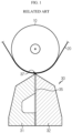
- FIG. 1 is a cross-sectional view of a conventional slot die coater.
- an active material slurry discharged from a slot die coater 30 is coated on an current collector 20 transferred by a coating roll 10.
- the active material slurry discharged from the slot die coater 30 is widely coated on one surface of the current collector 20 to form an active material layer.
- the slot die coater 30 includes two die blocks 31 and 32 and forms a single slot 35 between the two die blocks 31 and 32, and may form the active material layer of one layer by discharging one type of active material slurry through a discharge port 37 communicatively connected to the single slot 35.
- a slot die coater enables fast coating as compared with bar coating or comma coating, and thus has been widely applied in terms of high productivity.
- the slot die coater exemplified in FIG. 1 is a vertical die type in which an active material slurry is discharged in a direction opposite to gravity.
- the thickness of the active material layer which was about 130 ⁇ m gradually increased to reach 300 ⁇ m.
- the thick active material layer is formed with the conventional slot die coater 30
- coating is performed two times such as coating thinly and drying the active material layer and then coating and drying the active material layer, it takes a long time.
- a dual slot die coater capable of simultaneously coating two types of electrode active material slurries is required.
- a slot die coater constitutes a slot on a coupling surface of die blocks, basically three die blocks are required to include two slots like the dual slot die coater. Since a process using the dual slot die coater should use active material slurries simultaneously discharged from different discharge ports, it is quite difficult to form each active material layer to a desired thickness.
- a separation distance from a discharge port to the surface of a current collector is a coating gap, which is a very important variable in determining the coating quality of an active material layer.
- the thickness of each active material layer is affected by the discharge amount of each of the active material slurries through the discharge ports, the types of the active material slurries, and the coating gap.
- TD transverse direction
- the thickness of an active material layer is a very small value of several tens to several hundreds of ⁇ m, and should be very strictly controlled because even a change of only several ⁇ m in the thickness seriously affects the coating quality.
- the thickness of the active material layer needs to be very strictly controlled so as to exhibit uniform dimensional accuracy in the width direction in order to stably perform uniform coating in the width direction of the current collector.
- the width of the dual-slot die coater increases in order to use a long-width current collector to increase production, it becomes more difficult to perform uniform coating in the width direction, and precise control of the coating gap becomes more necessary.
- an appropriate coating gap range is determined according to the type of active material slurry.
- this coating gap is not only a variable that is adjusted sensitively enough to change even according to the fastening strength of bolts used for assembling between the die blocks, but also may be changed even by the force through which the active material slurry is discharged.
- the present disclosure is designed to solve the problems of the related art, and therefore the present disclosure is directed to providing a dual-slot die coater capable of easy coating gap adjustment and control of a width direction deviation of a coating gap.
- a dual-slot die coater including a first slot and a second slot for discharging a coating solution in a direction opposite to gravity
- the dual-slot die coater including a first die block vertically installed on a rear portion of an upper surface of a base, a second die block arranged on a front surface of the first die block to form the first slot between the second die block and the first die block, and a third die block arranged on a front surface of the second die block to form the second slot between the third die block and the second die block, and further including an alignment block provided between a front portion of the upper surface of the base and a lower surface of the second die block and fastened and coupled to the lower surface of the second die block and a lower surface of the first die block by bolts.
- the base and the first die block are integrated with each other.
- the first slot may be perpendicular to the base.
- a cross-section of the second die block may be a right triangle.
- a vertical length of each of the second die block and the third die block may be less than a vertical length of the first die block.
- the alignment block may include a stepped portion seated on the front portion of the upper surface of the base and a front surface of the base.
- the bolts may include a bolt fastened to the alignment block and the second die block by penetrating through a lower surface of the base, and a bolt fastened to the third die block by penetrating through the alignment block.
- the bolts may further include a bolt fastened to the base by penetrating through a front surface of the alignment block.
- the lower surface of the second die block and a lower surface of the third die block may closely contact an upper surface of the alignment block and may be arranged with each other.
- the first die block, the second die block, and the third die block may include a first die lip, a second die lip, and a third die lip as respective front end portions, respectively, and the first die lip, the second die lip, and the third die lip may be located on a same straight line.
- a first discharge port communicatively connected to the first slot may be formed between the first die lip and the second die lip, and a second discharge port communicatively connected to the second slot may be formed between the second die lip and the third die lip,the dual-slot die coater may extrude and coat an active material slurry through at least one of the first slot and the second slot on a surface of a continuously running substrate, and a step may be formed between the first discharge port and the second discharge port.
- the alignment block may be provided in plural in a width direction of the dual-slot die coater.
- a vertical cross-section of the alignment block may include a first cross-section portion and a second cross-section portion extending vertically from the first cross-section portion.
- the vertical cross-section may have a ' ⁇ ' or 'L' shape.
- the alignment block may be a single monolithic component rather than being divided into several components.
- respective lower surfaces of die blocks are aligned with each other through an alignment block.
- the respective lower surfaces of the die blocks may be naturally aligned with each other by a combination of the die blocks with respect to the alignment block. Then, misalignment between the die blocks may be prevented, and a distance between respective front end portions of the die blocks and a substrate, that is, a coating gap, may be always maintained at a desired degree. Since the die blocks are fixed through the alignment block, a once-determined coating gap is not easily changed during a process and is maintained, thereby suppressing occurrence of a variation in the coating gap in a width direction.
- the alignment block securely controls a uniform width direction gap through a large surface contact of a block.
- a coating product of uniform quality in particular, an electrode for a secondary battery, may be obtained using a dual-slot die coater with a uniform coating gap.
- the effect of maintaining the once adjusted coating gap is excellent. This has the effect of securing coating process ability and securing reproducibility.
- a dual-slot die coater it is possible to uniformly form a coating layer, in particular, an active material layer, to a desired thickness, and preferably, simultaneous coating of two types of active material slurries is possible, and thus there are effects that both performance and productivity are excellent.
- a plurality of alignment blocks may be arranged in the width direction of a dual-slot die coater. Then, precise control is possible without deviation of the coating gap in the width direction. Therefore, control may be made to exhibit uniform dimensional accuracy in order to stably perform uniform coating in the width direction even on a large-width current collector.
- An appropriate coating gap range may be determined according to the type of active material slurry.
- several types of alignment blocks having appropriate thicknesses are prepared, and a process is performed by replacing alignment blocks necessary for production processes, and thus, in order to use various active material slurries, a dual-slot die coater may be used universally even when a dual-slot die coater dedicated to each active material slurry is not individually provided.
- a quick response may be made to such dispersion by adjusting the coating gap by immediately replacing only the alignment block.
- the dual-slot die coater of the present disclosure when used to manufacture an electrode of a secondary battery by applying the active material slurry on a current collector while allowing the current collector to travel, there is an advantage that uniform coating is possible even under high-speed traveling or wide-width coating conditions.
- a dual-slot die coater is an apparatus that includes a first slot and a second slot for discharging a coating solution in a direction opposite to gravity and coats a coating solution in a double layer on a substrate.
- the 'substrate' described below is a current collector and the coating solution is an 'active material slurry'.
- Both a first coating solution and a second coating solution are active material slurries, and may refer to active material slurries that have the same or different composition (types of an active material, a conductive material, and a binder), content (an amount of each of the active material, the conductive material, and the binder), or physical properties.
- the dual-slot die coater according to an embodiment of the present disclosure is optimized for electrodes manufactured by applying at least two types of electrode active material slurries at the same time, or by applying at least two types of electrode active material slurries in an alternating manner to perform pattern coating.
- the substrate may be a porous support constituting a separator
- the first coating solution and the second coating solution may be organic materials having different compositions or physical properties. In other words, when thin film coating is required, any substrate, any first coating solution, and any second coating solution may be good.
- FIG. 2 is a schematic cross-sectional view of a dual-slot die coater according to an embodiment of the present disclosure
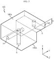
- FIG. 3 is a perspective view of an alignment block included in the dual-slot die coater of FIG. 2
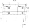
- FIG. 4 is a plan view of a lower surface of a dual-slot die coater according to an embodiment of the present disclosure.
- a dual-slot die coater 100 is an apparatus including a first slot 101 and a second slot 102 and capable of simultaneously or alternately coating two types of same or different coating solutions on a substrate 300 through the first slot 101 and the second slot 102.
- the dual-slot die coater 100 includes a base A, a first die block 110, a second die block 120, and a third die block 130.
- the dual-slot die coater 100 is installed in a substantially vertical direction (X direction) in which an active material slurry which is a coating solution is discharged (approximately: ⁇ 5 degrees).
- the base A may be viewed as a rectangular parallelepiped having a predetermined length in the left and right directions and extending in a direction (Z direction) perpendicular to the paper as shown in the drawings.
- the first die block 110 is vertically installed in a rear portion of an upper surface of the base A.
- the base A and the first die block 110 are integrally formed with each other.
- the first die block 110 has a plate-shaped structure in which the direction (Z direction) perpendicular to the paper is a width direction and the first die block 110 extends along this direction.
- the first die block 110 is put on the base A and assembled therewith.
- the second die block 120 is a block located in the middle of blocks constituting the dual-slot die coater 100, and is a block disposed between the first die block 110 and the second die block 130 to form a dual slot.
- a cross-section of the second die block 120 of the present embodiment is a right triangle, but is not necessarily limited to this shape.
- the cross section may be provided as an isosceles triangle.
- the second die block 120 is disposed on a front surface of the first die block 110.
- the second die block 120 has a plate-shaped structure in which the direction (Z direction) perpendicular to the paper is a width direction and the second die block 120 extends along this direction.
- a first surface 120a of the second die block 120 facing the first die block 110 lies almost perpendicular to the base A.
- the first surface 120a of the second die block 120 is a vertical surface.
- a second surface 110b of the first die block 110 facing the first surface 120a of the second die block 120, and the first surface 120a (that is, a surface forming a rear surface of an outer circumferential surface of the dual-slot die coater 100) opposite to the second surface 110b also lie almost perpendicular to the base A.
- the first and second surfaces 120a and 120b of the first die block 110 are vertical surfaces.
- the first surface 120a of the second die block 120 and a first surface 110a of the first die block 110, and the second surface 110b are almost parallel to each other.
- a forwardly-inclined inclined surface 110a' is formed above the first surface 110a, and accordingly a cross section of an upper portion of the first die block 110 is substantially triangular.
- the third die block 130 is disposed on a front surface of the second die block 120.
- the third die block 130 also has a plate-shaped structure in which the direction (Z direction) perpendicular to the paper is a width direction and the second die block 120 extends along this direction.
- the second surface 120b of the second die block 120 facing the third die block 130, the first surface 130a of the third die block 130 facing the second surface 120b of the second die block 120, and the second surface 130b i.e., a surface that forms a front surface of the outer circumferential surface of the dual-slot die coater 100), which is opposite to the first surface 130a, are almost parallel to one another.
- a rearwardly inclined inclined surface 130b' is formed above the second surface 130b.
- a cross section of an upper portion of the third die block 130 is also substantially triangular.
- a surface 130b" below the second surface 130b of the third die block 130 lies almost perpendicular to the base A. In other words, the surface 130b" is also a vertical surface.
- first die block 110, the second die block 120, and the third die block 130 which are opposite to a direction in which the active material slurry is discharged, namely, lower surfaces 110c, 120c, and 130c, lie almost horizontally (Y direction).
- Y direction a direction in which the active material slurry is discharged
- corners formed by surfaces have portions formed at right angles, there is a right angle portion in the cross section, and since a vertical or horizontal surface is used as a reference surface, manufacturing or handling of the die blocks 110, 120, and 130 is easy and the precision thereof is guaranteed.
- the first die block 110, the second die block 120, and the third die block 130 are not necessarily limited to shapes taken as the above examples, and may be configured, for example, as horizontal dies with the direction in which the active material slurry is discharged as a horizontal direction and the lower surfaces 110c, 120c, and 130c as rear surfaces.
- the die blocks 110, 120, and 130 are made of, for example, a SUS material.
- Materials that are easy to process such as SUS420J2, SUS630, SUS440C, SUS304, and SUS316L, may be used.
- SUS has advantages in that it is easy to process, inexpensive, has high corrosion resistance, and may be manufactured in a desired shape at low cost.
- the first die block 110 is a block located behind and on the right side in FIG. 2 , from among the blocks constituting the dual-slot die coater 100, and, because the second surface 110b facing the second die block 120 is perpendicular to the base A, the first slot 101 may be perpendicular to the base A.
- the first slot 101 may be formed where the first die block 110 and the second die block 120 face each other.
- the first slot 101 is formed by a combination of the first die block 110 and the second die block 120.
- a first spacer 113 is interposed between the first die block 110 and the second die block 120 to provide a gap therebetween, so that the first slot 101 corresponding to a passage through which a first coating solution 50 may flow may be formed.
- a thickness of the first spacer 113 determines a vertical width (slot gap) of the first slot 101.
- the first spacer 113 includes an opening portion in which one area is cut, and may be interposed in a remaining portion except for one side of a border area of an opposite surface of each of the first die block 110 and the second die block 120. Accordingly, a first discharge port 101a through which the first coating solution 50 may be discharged to the outside is formed only between a front end portion of the first die block 110 and a front end portion of the second die block 120.
- the front end portion of the first die block 110 and the front end portion of the second die block 120 are defined as a first die lip 111 and a second die lip 121, respectively.
- the first discharge port 101a may be formed by making the first die lip 111 and the second die lip 121 spaced apart from each other.
- Each of the first die lip 111 and the second die lip 121 extends in the width direction, and may be a rectangular parallelepiped having a flat upper surface.
- the first spacer 113 functions as a gasket to prevent the first coating solution 50 from leaking into a gap between the first die block 110 and the second die block 120 except for the area where the first discharge port 101a is formed, and thus the first spacer 113 is preferably made of a material having sealing properties.
- the first die block 110 includes a first manifold 112 having a predetermined depth on the second surface 110b facing the second die block 120 and communicatively connected to the first slot 101.
- the first manifold 112 is a space provided from the second surface 110b of the first die block 110 facing the second die block 120 toward the first surface 110a opposite to the second surface 110b.
- the first manifold 112 is connected to a first coating solution supply chamber (not shown) installed outside through a supply pipe to receive the first coating solution 50. When the first coating solution 50 is filled in the first manifold 112, the flow of the first coating solution 50 is induced along the first slot 101 and discharged to the outside through the first discharge port 101a.
- the third die block 130 is arranged in front of the second die block 120 and forms the second slot 102 between the third die block 130 and the second die block 120.
- the second slot 102 is thus formed where the second die block 120 and the third die block 130 face to each other.
- the second slot 102 is formed by a combination of the third die block 130 and the second die block 120.
- a second spacer 133 may be interposed between the second die block 120 and the third die block 130 to provide a gap therebetween. Accordingly, the second slot 102 corresponding to a passage through which a second coating solution 60 may flow is formed. In this case, a vertical width (slot gap) of the second slot 102 is determined by the second spacer 133.
- the second spacer 133 which also has a structure similar to that of the above-described first spacer 113, includes an opening portion in which one area is cut, and may be interposed in the remaining portion except for one side of a border area of an opposite surface of each of the second die block 120 and the third die block 130.
- a circumferential direction of the second spacer 133 except for the front of the second slot 102 is blocked, and the second discharge port 102a is formed only between the front end portion of the second die block 120 and a front end portion of the third die block 130.
- the front end portion of the third die block 130 is defined as a third die lip 131.
- the second discharge port 102a may be formed by making the second die lip 121 and the third die lip 131 spaced apart from each other.
- the third die lip 131 also extends in the width direction, and may be a rectangular parallelepiped having a flat upper surface.
- the third die block 130 includes a second manifold 132 having a predetermined depth on the first surface 130a facing the second die block 120 and communicatively connected to the second slot 102.
- the second manifold 132 is a space provided from the first surface 130a toward the second surface 130b opposite to the first surface 130a.
- the second manifold 132 is connected to a supply chamber of the second coating solution 60 installed outside through a supply pipe to receive the second coating solution 60.
- the flow of the second coating solution 60 is induced along the second slot 102 communicatively connected to the second manifold 132 and discharged to the outside through the second discharge port 102a.
- the second slot 102 and the first slot 101 form a certain angle, and the angle may be approximately 20 degrees to 70 degrees.
- the second slot 102 and the first slot 101 may intersect each other at one point, and the second discharge port 102a and the first discharge port 101a may be provided near the intersection. Accordingly, discharge points of the first coating solution 50 and the second coating solution 60 may be concentrated approximately at one point.
- the first and second manifolds 112 and 132 form the first die block 110 and the third die block 130, respectively. This may less affect deformation of the second die block 120, which is structurally weakest.
- the second die block 120 when the second die block 120 is divided into a left die and a right die, the left die is configured to move integrally with the third die block 130, and the right die is configured to move integrally with the first die block 110, the second die block 120 may be implemented as a structure in which a left die block and a right die block are slidable at an interface between a left die and a right die, and thus may be implemented as a structure facilitating location changes in the first slot 101 and the second slot 102.
- An angle ⁇ between the second surface 120b of the second die block 120 facing the third die block 130 and the first surface 120a of the second die block 120 facing the first die block 110 may be preferably determined within a range in which an active material slurry discharged from the second discharge port 102a and an active material slurry discharged from the first discharge port 101a do not form a vortex immediately after being simultaneously discharged.
- the angle ⁇ is too small, the second die block 120 is too thin to be very vulnerable to deformation and torsion.
- a rotatably provided coating roll 200 is disposed over the dual-slot die coater 100, and, while the substrate 300 to be coated by rotating the coating roll 200 is being driven, the first coating solution 50 and the second coating solution 60 are continuously contacted with the surface of the substrate 300 so that the substrate 300 may be coated in a double layer.
- supply and interruption of the first coating solution 50 and supply and interruption of the second coating solution 60 are alternately performed so that pattern-coating may be intermittently performed on the substrate 300.
- the dual-slot die coater 100 further includes an alignment block 140 that is fastened to the lower surfaces 120c and 130c of the die blocks 120 and 130, which are opposite to the front end portions of the die blocks 120 and 130, by bolts 141 and 142 to bond the two die blocks 120 and 130 together.
- the alignment block 140 is included between a front portion of the upper surface of the base A and the lower surface 120c of the second die block 120.
- a vertical length h1 of each of the second die block 120 and the third die block 130 is less than a vertical length h2 of the first die block 110 is taken.
- a vertical length indicates a vertical distance from the lower surface of each die block to a die lip.
- This space may be a space in which an upper surface is formed on the lower surface 120c of the second die block 120, an upper portion is formed by the upper surface of the base A, a front surface is open, a rear surface is formed by the front surface of the first die block 110, and left and right side portions are open.
- the alignment block 140 is installed in this space.
- the alignment block 140 may include a stepped portion 140' seated on the front portion of the upper surface of the base A and the front surface of the base A.
- the thickness D of the stepped portion 140' may correspond to a difference between the vertical length h1 of each of the second die block 120 and the third die block 130 and the vertical length h2 of the first die block 110.
- the bolt 141 penetrates through the lower surface of the base A and is fastened to the alignment block 140 and the second die block 120 in a vertical direction.
- the bolt 142 penetrates through the alignment block 140 and is fastened to the third die block 130 in a vertical direction.
- a bolt 143 penetrates through the front surface of the alignment block 140 and is fastened to the base A in a horizontal direction.
- the bolts 141, 142, and 143 may be fastened at locations where they do not interfere with one another.
- the lower surface 120c of the second die block 120 and the lower surface 130c of the third die block 130 may be in contact with the upper surface of the alignment block 140 and aligned with each other, and the lower surface 120c of the second die block 120 and the lower surface 130c of the third die block 130 may have a step with the lower surface 110c of the first die block 110.
- the alignment block 140 has an upper surface 140a that is in contact with the lower surface 120c of the second die block 120 and the lower surface 130c of the third die block 130.
- the lower surface 140b includes the stepped portion 140' having the thickness D, which is less than a thickness of the other portion.
- the stepped portion 140' has a structure capable of being seated on the front portion of the upper surface of the base A and the front surface of the base A.
- holes H through which the bolts 141, 142, and 143 penetrate may be further formed to fasten the bolts 141, 142, and 143. The number of holes H and the locations of the holes H may be changed from those shown in the drawings.
- a vertical cross-section of the alignment block 140 that passes through all of the upper surface 140a, the lower surface 140b, and the stepped portion 140' includes a first cross-section portion and a second cross-section portion extending vertically from the first cross-section portion.
- the vertical cross-section has a ' ⁇ ' or 'L' shape. In this way, processing of a simple block shape is not cumbersome, and precise processing is possible. By doing this, similar to the die blocks 110, 120, and 130, since corners formed by surfaces of the alignment block 140 are at right angles, there is a right angle portion in the cross section, and since a vertical or horizontal surface is used as a reference surface, manufacturing or handling of the alignment block 140 is easy and the precision thereof is guaranteed.
- facing portions thereof may be supported by one another with a high degree of surface contact, and thus may be fastened and fixed and may be maintained very well.
- the dual-slot die coater may be generally formed of an SUS material.
- a rubber ring or other soft material is placed between components and sealed to suppress leakage.
- this sealing method is not suitable for controlling a uniform assembly shape (e.g., an assembly deviation of less than 10 ⁇ m), and thus is difficult to apply to a dual-slot die coater.
- a die block processed with a very high precision needs to be assembled by bolting.
- bolting is at a high pressure of about 200 to 350N.
- this high-pressure bolting cause a minute stress imbalance, block die deformation may be accordingly induced, and deformation or twisting of die blocks occur due to the pressure of a coating solution supplied during coating.
- the alignment block 140 having a cross section of a ' ⁇ ' or 'L' shape is a structure that may withstand such high-pressure bolting.
- the alignment block 140 may be a single monolithic component rather than being divided into several components. In other words, the alignment block 140 is an integral, seamless component. Accordingly, not only accuracy of the alignment block 140 is improved during assembly, but also the structure of the alignment block 140 is robust, so the alignment block 140 has excellent stability against external shocks during handling and use.
- the alignment block 140 bonds the third die block 130 and the second die block 120 together. Because the lower surface 130c of the third die block 130 and the lower surface 120c of the second die block 120 are bonded in parallel, when the respective vertical lengths h1 of the second die block 120 and the third die block 130 are identical to each other, the third die lip 131 and the second die lip 121, which are respectively the front end portions of the die blocks 130 and 120, may be located on the same straight line. In other words, the third die lip 131 and the second die lip 121 may be at the same height from the base A, and a lower circumferential surface of the coating roll 200 is located with a coating gap over the third die lip 131 and the second die lip 121. In this way, the alignment block 140 determines locations of the third die lip 131 and the second die lip 121, thereby affecting the coating gap.
- alignment blocks 140 may be arranged in the width direction of the dual-slot die coater 100.
- the alignment block 140 securely controls a uniform width direction gap through a large surface contact of a block.
- the third die block 130 and the second die block 120 are combined to move integrally, and relative locations of the second discharge port 102a and the first discharge port 101a may be adjusted.
- the degree of location adjustment varies according to the thickness D of the stepped portion 140' of the alignment block 140, and the coating gap is determined accordingly.
- location misalignment between the die blocks 110, 120, and 130 may be prevented.
- the coating gap is easily determined through a combination of the die blocks 130 and 120 with the alignment block 140. Therefore, inconvenience of adjusting the coating gap while dismantling the die blocks 130, 120, and 110 and adjusting the positions thereof may be greatly addressed, and assembly precision may be improved.
- the present embodiment illustrates an example in which the vertical length h1 of the third die block 130 (vertical distance from the lower surface 130c to the third die lip 131) and the vertical length of the second die block 120 (vertical distance from the lower surface 120c to the second die lip 121) is less than the vertical length h2 of the first die block 110 (vertical distance from the lower surface 110c to the first die lip 111).
- the alignment block 140 including the stepped portion 140' having the thickness D corresponding to a difference between the vertical lengths h1 and h2 is fastened to the third die block 130 and the second die block 120, the first die lip 111, the second die lip 121, and the third die lip 131 may be located on the same straight line.
- the entirety of the dual-slot die coater 100 may be coated with various layers while moving forwards or backwards with respect to the substrate 300.
- fastening of the alignment block 140 may make the second die lip 121 and the third die lip 131 protrude toward the substrate 300 farther than the first die lip 111. Then, a step is formed between the first discharge port 101a and the second discharge port 102a.
- a distance between the third die lip 131, the second die lip 121, and the first die lip 111, which are the respective front end portions of the die blocks 130, 120, and 110, and the substrate 300, namely, the coating gap, may be always maintained at a desired level, and the die blocks 130 and 120 are fixed to each other, and accordingly a once-determined coating gap is maintained without changing during a process.
- a coating product of uniform quality in particular, an electrode for a secondary battery, may be obtained using a dual-slot die coater with a uniform coating gap.
- a dual-slot die coater it is possible to uniformly form a coating layer, in particular, an active material layer, to a desired thickness, and preferably, simultaneous coating of two types of active material slurries is possible, and thus there are effects that both performance and productivity are excellent.
- inclusion of a plurality of alignment blocks 140 in the width direction of the dual-slot die coater 100 enables precise control without a deviation of the coating gap even in the width direction.
- An appropriate coating gap range is determined according to the type of active material slurry.
- several types of alignment blocks having stepped portions with appropriate thicknesses are prepared, and a process is performed by replacing an alignment block necessary for each production process, and thus, in order to use various active material slurries, a dual-slot die coater may be used universally even when a dual-slot die coater dedicated to each active material slurry is not individually provided. Moreover, even when dispersion exists in an active material slurry, a quick response may be made to such dispersion by immediately replacing only the alignment block.
- the dual-slot die coater of the present disclosure when used to manufacture an electrode of a secondary battery by applying the active material slurry on a current collector while allowing the current collector to travel, there is an advantage that uniform coating is possible even under high-speed traveling or wide-width application conditions.
- a case of coating a coating solution in two layers or a case of pattern-coating by alternately supplying a coating solution has been described as an example.
- the present disclosure is applicable to a case where three or more layers are simultaneously coated by providing three or more slots.
Landscapes
- Engineering & Computer Science (AREA)
- Manufacturing & Machinery (AREA)
- Chemical & Material Sciences (AREA)
- Chemical Kinetics & Catalysis (AREA)
- Electrochemistry (AREA)
- General Chemical & Material Sciences (AREA)
- Coating Apparatus (AREA)
- Battery Electrode And Active Subsutance (AREA)
Abstract
Description
- The present disclosure relates to a dual-slot die coater capable of simultaneously forming two or more layers by wetting. In particular, the present disclosure relates to a dual-slot die coater having a means for controlling a width-direction deviation of a coating gap. The present application claims priority to
Korean Patent Application No. 10-2020-0185693 filed on December 29, 2020 - As technology development and demand for mobile devices increase, the demand for secondary batteries as an energy source is rapidly increasing, and such secondary batteries essentially include an electrode assembly which is a power generation element. The electrode assembly has a form in which a positive electrode, a separator, and a negative electrode are stacked at least once, and the positive electrode and the negative electrode are prepared by coating and drying a positive electrode active material slurry and a negative electrode active material slurry on current collectors made of aluminum foil and copper foil, respectively. In order to equalize charging/discharging features of secondary batteries, the positive electrode active material slurry and the negative electrode active material slurry should be uniformly coated on the current collectors, and a slot die coater is conventionally used therefor.
-
FIG. 1 is a cross-sectional view of a conventional slot die coater. - Referring to
FIG. 1 , in an electrode manufacturing method using the slot die coater, an active material slurry discharged from aslot die coater 30 is coated on ancurrent collector 20 transferred by acoating roll 10. The active material slurry discharged from theslot die coater 30 is widely coated on one surface of thecurrent collector 20 to form an active material layer. Theslot die coater 30 includes twodie blocks single slot 35 between the twodie blocks discharge port 37 communicatively connected to thesingle slot 35. A slot die coater enables fast coating as compared with bar coating or comma coating, and thus has been widely applied in terms of high productivity. The slot die coater exemplified inFIG. 1 is a vertical die type in which an active material slurry is discharged in a direction opposite to gravity. - In order to manufacture a secondary battery of high energy density, the thickness of the active material layer which was about 130 µm gradually increased to reach 300 µm. When the thick active material layer is formed with the conventional
slot die coater 30, since migration of a binder and a conductive material in the active material slurry deepens during drying, a final electrode is manufactured non-uniformly. In order to solve this problem, when coating is performed two times such as coating thinly and drying the active material layer and then coating and drying the active material layer, it takes a long time. In order to simultaneously improve electrode performance and productivity, a dual slot die coater capable of simultaneously coating two types of electrode active material slurries is required. - Since a slot die coater constitutes a slot on a coupling surface of die blocks, basically three die blocks are required to include two slots like the dual slot die coater. Since a process using the dual slot die coater should use active material slurries simultaneously discharged from different discharge ports, it is quite difficult to form each active material layer to a desired thickness.
- A separation distance from a discharge port to the surface of a current collector is a coating gap, which is a very important variable in determining the coating quality of an active material layer. In general, the thickness of each active material layer is affected by the discharge amount of each of the active material slurries through the discharge ports, the types of the active material slurries, and the coating gap. When the coating gap is uniform in a width direction (transverse direction (TD)) of the current collector, stable coating is possible, and, when there is a coating gap deviation in the width direction, a coating width and the shape of a non-coated portion boundary have a lot of influence. The thickness of an active material layer is a very small value of several tens to several hundreds of µm, and should be very strictly controlled because even a change of only several µm in the thickness seriously affects the coating quality. The thickness of the active material layer needs to be very strictly controlled so as to exhibit uniform dimensional accuracy in the width direction in order to stably perform uniform coating in the width direction of the current collector. However, when the width of the dual-slot die coater increases in order to use a long-width current collector to increase production, it becomes more difficult to perform uniform coating in the width direction, and precise control of the coating gap becomes more necessary.
- In addition, an appropriate coating gap range is determined according to the type of active material slurry. In a production process, it is necessary to manufacture various products using several types of active material slurries instead of using one type of active material slurry. In order to use various active material slurries, it is difficult to individually provide a dual-slot die coater dedicated to each active material slurry. Therefore, it is necessary to coat a certain type of active material slurry by using one dual-slot die coater and then coat another type of active material slurry by using the dual-slot die coater. In this case, a previously set coating gap needs to be changed. In addition, since it is difficult to always uniformly manufacture the same type of active material slurries, there is dispersion in physical properties of the active material slurries depending on a manufacturing time point, so it is necessary to respond to such dispersion. Moreover, coating gap control becomes more important because fast coating reveals great coating quality variations due to dispersion in the physical properties of active material slurries.
- In the conventional art, in order to produce a desired coating gap, it is necessary to repeat a task of disassembling and reassembling each die block while experimentally performing a coating process several times to adjust and check the coating gap. However, this coating gap is not only a variable that is adjusted sensitively enough to change even according to the fastening strength of bolts used for assembling between the die blocks, but also may be changed even by the force through which the active material slurry is discharged.
- In order to configure a device having a foot print and volume similar to the conventional
slot die coater 30 including one slot, the thickness of each of the die blocks must be thin, and for this reason, there is a problem of being structurally vulnerable to deformation and torsion inevitably. When deformation or torsion occurs, the painstakingly adjusted coating gap is twisted, which is a serious problem of causing defects in an electrode process. - The present disclosure is designed to solve the problems of the related art, and therefore the present disclosure is directed to providing a dual-slot die coater capable of easy coating gap adjustment and control of a width direction deviation of a coating gap.
- These and other objects and advantages of the present disclosure may be understood from the following detailed description and will become more fully apparent from the exemplary embodiments of the present disclosure. Also, it will be easily understood that the objects and advantages of the present disclosure may be realized by the means shown in the appended claims and combinations thereof.
- In one aspect of the present disclosure, there is provided a dual-slot die coater including a first slot and a second slot for discharging a coating solution in a direction opposite to gravity, the dual-slot die coater including a first die block vertically installed on a rear portion of an upper surface of a base, a second die block arranged on a front surface of the first die block to form the first slot between the second die block and the first die block, and a third die block arranged on a front surface of the second die block to form the second slot between the third die block and the second die block, and further including an alignment block provided between a front portion of the upper surface of the base and a lower surface of the second die block and fastened and coupled to the lower surface of the second die block and a lower surface of the first die block by bolts.
- According to an embodiment of the present disclosure, the base and the first die block are integrated with each other.
- The first slot may be perpendicular to the base.
- A cross-section of the second die block may be a right triangle.
- A vertical length of each of the second die block and the third die block may be less than a vertical length of the first die block.
- The alignment block may include a stepped portion seated on the front portion of the upper surface of the base and a front surface of the base.
- The bolts may include a bolt fastened to the alignment block and the second die block by penetrating through a lower surface of the base, and a bolt fastened to the third die block by penetrating through the alignment block.
- The bolts may further include a bolt fastened to the base by penetrating through a front surface of the alignment block.
- The lower surface of the second die block and a lower surface of the third die block may closely contact an upper surface of the alignment block and may be arranged with each other.
- The first die block, the second die block, and the third die block may include a first die lip, a second die lip, and a third die lip as respective front end portions, respectively, and the first die lip, the second die lip, and the third die lip may be located on a same straight line.
- A first discharge port communicatively connected to the first slot may be formed between the first die lip and the second die lip, and a second discharge port communicatively connected to the second slot may be formed between the second die lip and the third die lip,the dual-slot die coater may extrude and coat an active material slurry through at least one of the first slot and the second slot on a surface of a continuously running substrate, and a step may be formed between the first discharge port and the second discharge port.
- The alignment block may be provided in plural in a width direction of the dual-slot die coater.
- A vertical cross-section of the alignment block may include a first cross-section portion and a second cross-section portion extending vertically from the first cross-section portion. In other words, the vertical cross-section may have a '¬' or 'L' shape.
- The alignment block may be a single monolithic component rather than being divided into several components.
- According to the present disclosure, respective lower surfaces of die blocks are aligned with each other through an alignment block. The respective lower surfaces of the die blocks may be naturally aligned with each other by a combination of the die blocks with respect to the alignment block. Then, misalignment between the die blocks may be prevented, and a distance between respective front end portions of the die blocks and a substrate, that is, a coating gap, may be always maintained at a desired degree. Since the die blocks are fixed through the alignment block, a once-determined coating gap is not easily changed during a process and is maintained, thereby suppressing occurrence of a variation in the coating gap in a width direction.
- Therefore, according to the present disclosure, there is no need to adjust the coating gap while disassembling and reassembling the die blocks which are structurally weak because of their small thicknesses, and a constant coating gap may be maintained all the time by a simple operation of coupling the die blocks to the alignment block. The alignment block securely controls a uniform width direction gap through a large surface contact of a block.
- According to the present disclosure, even considering that a die block is deformed by the pressure of a discharged active material slurry, there is an effect of uniformly controlling the coating amount and a coating quality by maintaining a uniform (±2%) coating gap. Thus, a coating product of uniform quality, in particular, an electrode for a secondary battery, may be obtained using a dual-slot die coater with a uniform coating gap.
- As described above, according to the present disclosure, even when the discharge pressure of the active material slurry increases and thin die blocks are used, the effect of maintaining the once adjusted coating gap is excellent. This has the effect of securing coating process ability and securing reproducibility.
- Using such a dual-slot die coater, it is possible to uniformly form a coating layer, in particular, an active material layer, to a desired thickness, and preferably, simultaneous coating of two types of active material slurries is possible, and thus there are effects that both performance and productivity are excellent.
- According to the present disclosure, a plurality of alignment blocks may be arranged in the width direction of a dual-slot die coater. Then, precise control is possible without deviation of the coating gap in the width direction. Therefore, control may be made to exhibit uniform dimensional accuracy in order to stably perform uniform coating in the width direction even on a large-width current collector.
- An appropriate coating gap range may be determined according to the type of active material slurry. In the present disclosure, several types of alignment blocks having appropriate thicknesses are prepared, and a process is performed by replacing alignment blocks necessary for production processes, and thus, in order to use various active material slurries, a dual-slot die coater may be used universally even when a dual-slot die coater dedicated to each active material slurry is not individually provided. Moreover, even when dispersion exists in an active material slurry, a quick response may be made to such dispersion by adjusting the coating gap by immediately replacing only the alignment block.
- As described above, when the dual-slot die coater of the present disclosure is used to manufacture an electrode of a secondary battery by applying the active material slurry on a current collector while allowing the current collector to travel, there is an advantage that uniform coating is possible even under high-speed traveling or wide-width coating conditions.
- The accompanying drawings illustrate a preferred embodiment of the present disclosure and together with the foregoing disclosure, serve to provide further understanding of the technical features of the present disclosure, and thus, the present disclosure is not construed as being limited to the drawing.
-
FIG. 1 is a schematic cross-sectional view of a conventional slot die coater. -
FIG. 2 is a schematic cross-sectional view of a dual-slot die coater according to an embodiment of the present disclosure. -
FIG. 3 is a perspective view of an alignment block included in the dual-slot die coater ofFIG. 2 . -
FIG. 4 is a plan view of a lower surface of a dual-slot die coater according to an embodiment of the present disclosure. - Hereinafter, preferred embodiments of the present disclosure will be described in detail with reference to the accompanying drawings. Prior to the description, it should be understood that the terms used in the specification and the appended claims should not be construed as limited to general and dictionary meanings, but interpreted based on the meanings and concepts corresponding to technical aspects of the present disclosure on the basis of the principle that the inventor is allowed to define terms appropriately for the best explanation. Therefore, the description proposed herein is just a preferable example for the purpose of illustrations only, not intended to limit the scope of the disclosure, so it should be understood that other equivalents and modifications could be made thereto without departing from the scope of the disclosure.
- A dual-slot die coater according to an embodiment of the present disclosure is an apparatus that includes a first slot and a second slot for discharging a coating solution in a direction opposite to gravity and coats a coating solution in a double layer on a substrate. The 'substrate' described below is a current collector and the coating solution is an 'active material slurry'. Both a first coating solution and a second coating solution are active material slurries, and may refer to active material slurries that have the same or different composition (types of an active material, a conductive material, and a binder), content (an amount of each of the active material, the conductive material, and the binder), or physical properties. The dual-slot die coater according to an embodiment of the present disclosure is optimized for electrodes manufactured by applying at least two types of electrode active material slurries at the same time, or by applying at least two types of electrode active material slurries in an alternating manner to perform pattern coating. However, the scope of the present disclosure is not limited thereto. For example, the substrate may be a porous support constituting a separator, and the first coating solution and the second coating solution may be organic materials having different compositions or physical properties. In other words, when thin film coating is required, any substrate, any first coating solution, and any second coating solution may be good.
-
FIG. 2 is a schematic cross-sectional view of a dual-slot die coater according to an embodiment of the present disclosure, andFIG. 3 is a perspective view of an alignment block included in the dual-slot die coater ofFIG. 2 .FIG. 4 is a plan view of a lower surface of a dual-slot die coater according to an embodiment of the present disclosure. - A dual-
slot die coater 100 according to an embodiment of the present disclosure is an apparatus including afirst slot 101 and asecond slot 102 and capable of simultaneously or alternately coating two types of same or different coating solutions on asubstrate 300 through thefirst slot 101 and thesecond slot 102. Referring toFIG. 2 , the dual-slot die coater 100 includes a base A, afirst die block 110, asecond die block 120, and athird die block 130. - In
FIG. 2 , the dual-slot die coater 100 is installed in a substantially vertical direction (X direction) in which an active material slurry which is a coating solution is discharged (approximately: ± 5 degrees). - The base A may be viewed as a rectangular parallelepiped having a predetermined length in the left and right directions and extending in a direction (Z direction) perpendicular to the paper as shown in the drawings. The
first die block 110 is vertically installed in a rear portion of an upper surface of the base A. Preferably, the base A and thefirst die block 110 are integrally formed with each other. Thefirst die block 110 has a plate-shaped structure in which the direction (Z direction) perpendicular to the paper is a width direction and thefirst die block 110 extends along this direction. Thefirst die block 110 is put on the base A and assembled therewith. When the base A and thefirst die block 110 are integrally formed with each other in this way, alignment with respect to the base A is not necessary, and the base A and thefirst die block 110 may be integrally handled, and thus handling is convenient. - The
second die block 120 is a block located in the middle of blocks constituting the dual-slot die coater 100, and is a block disposed between thefirst die block 110 and thesecond die block 130 to form a dual slot. A cross-section of thesecond die block 120 of the present embodiment is a right triangle, but is not necessarily limited to this shape. For example, the cross section may be provided as an isosceles triangle. - The
second die block 120 is disposed on a front surface of thefirst die block 110. Thesecond die block 120 has a plate-shaped structure in which the direction (Z direction) perpendicular to the paper is a width direction and thesecond die block 120 extends along this direction. Afirst surface 120a of thesecond die block 120 facing thefirst die block 110 lies almost perpendicular to the base A. In other words, thefirst surface 120a of thesecond die block 120 is a vertical surface. Asecond surface 110b of thefirst die block 110 facing thefirst surface 120a of thesecond die block 120, and thefirst surface 120a (that is, a surface forming a rear surface of an outer circumferential surface of the dual-slot die coater 100) opposite to thesecond surface 110b also lie almost perpendicular to the base A. In other words, the first andsecond surfaces first die block 110 are vertical surfaces. In this way, thefirst surface 120a of thesecond die block 120 and afirst surface 110a of thefirst die block 110, and thesecond surface 110b are almost parallel to each other. In thefirst die block 110, a forwardly-inclinedinclined surface 110a' is formed above thefirst surface 110a, and accordingly a cross section of an upper portion of thefirst die block 110 is substantially triangular. - The
third die block 130 is disposed on a front surface of thesecond die block 120. Thethird die block 130 also has a plate-shaped structure in which the direction (Z direction) perpendicular to the paper is a width direction and thesecond die block 120 extends along this direction. Thesecond surface 120b of thesecond die block 120 facing thethird die block 130, thefirst surface 130a of thethird die block 130 facing thesecond surface 120b of thesecond die block 120, and thesecond surface 130b (i.e., a surface that forms a front surface of the outer circumferential surface of the dual-slot die coater 100), which is opposite to thefirst surface 130a, are almost parallel to one another. In thethird die block 130, a rearwardly inclinedinclined surface 130b' is formed above thesecond surface 130b. A cross section of an upper portion of thethird die block 130 is also substantially triangular. Asurface 130b" below thesecond surface 130b of thethird die block 130 lies almost perpendicular to the base A. In other words, thesurface 130b" is also a vertical surface. - Surfaces of the
first die block 110, thesecond die block 120, and thethird die block 130 which are opposite to a direction in which the active material slurry is discharged, namely,lower surfaces - The
first die block 110, thesecond die block 120, and thethird die block 130 are not necessarily limited to shapes taken as the above examples, and may be configured, for example, as horizontal dies with the direction in which the active material slurry is discharged as a horizontal direction and thelower surfaces - The die blocks 110, 120, and 130 are made of, for example, a SUS material. Materials that are easy to process, such as SUS420J2, SUS630, SUS440C, SUS304, and SUS316L, may be used. SUS has advantages in that it is easy to process, inexpensive, has high corrosion resistance, and may be manufactured in a desired shape at low cost.
- The
first die block 110 is a block located behind and on the right side inFIG. 2 , from among the blocks constituting the dual-slot die coater 100, and, because thesecond surface 110b facing thesecond die block 120 is perpendicular to the base A, thefirst slot 101 may be perpendicular to the base A. Thefirst slot 101 may be formed where thefirst die block 110 and thesecond die block 120 face each other. Thefirst slot 101 is formed by a combination of thefirst die block 110 and thesecond die block 120. For example, afirst spacer 113 is interposed between thefirst die block 110 and thesecond die block 120 to provide a gap therebetween, so that thefirst slot 101 corresponding to a passage through which afirst coating solution 50 may flow may be formed. In this case, a thickness of thefirst spacer 113 determines a vertical width (slot gap) of thefirst slot 101. - The
first spacer 113 includes an opening portion in which one area is cut, and may be interposed in a remaining portion except for one side of a border area of an opposite surface of each of thefirst die block 110 and thesecond die block 120. Accordingly, afirst discharge port 101a through which thefirst coating solution 50 may be discharged to the outside is formed only between a front end portion of thefirst die block 110 and a front end portion of thesecond die block 120. The front end portion of thefirst die block 110 and the front end portion of thesecond die block 120 are defined as afirst die lip 111 and asecond die lip 121, respectively. In other words, thefirst discharge port 101a may be formed by making thefirst die lip 111 and thesecond die lip 121 spaced apart from each other. Each of thefirst die lip 111 and thesecond die lip 121 extends in the width direction, and may be a rectangular parallelepiped having a flat upper surface. - For reference, the
first spacer 113 functions as a gasket to prevent thefirst coating solution 50 from leaking into a gap between thefirst die block 110 and thesecond die block 120 except for the area where thefirst discharge port 101a is formed, and thus thefirst spacer 113 is preferably made of a material having sealing properties. - The
first die block 110 includes afirst manifold 112 having a predetermined depth on thesecond surface 110b facing thesecond die block 120 and communicatively connected to thefirst slot 101. Thefirst manifold 112 is a space provided from thesecond surface 110b of thefirst die block 110 facing thesecond die block 120 toward thefirst surface 110a opposite to thesecond surface 110b. Thefirst manifold 112 is connected to a first coating solution supply chamber (not shown) installed outside through a supply pipe to receive thefirst coating solution 50. When thefirst coating solution 50 is filled in thefirst manifold 112, the flow of thefirst coating solution 50 is induced along thefirst slot 101 and discharged to the outside through thefirst discharge port 101a. - The
third die block 130 is arranged in front of thesecond die block 120 and forms thesecond slot 102 between thethird die block 130 and thesecond die block 120. Thesecond slot 102 is thus formed where thesecond die block 120 and thethird die block 130 face to each other. In other words, thesecond slot 102 is formed by a combination of thethird die block 130 and thesecond die block 120. - Like the
first slot 101 described above, asecond spacer 133 may be interposed between thesecond die block 120 and thethird die block 130 to provide a gap therebetween. Accordingly, thesecond slot 102 corresponding to a passage through which asecond coating solution 60 may flow is formed. In this case, a vertical width (slot gap) of thesecond slot 102 is determined by thesecond spacer 133. - In addition, the
second spacer 133, which also has a structure similar to that of the above-describedfirst spacer 113, includes an opening portion in which one area is cut, and may be interposed in the remaining portion except for one side of a border area of an opposite surface of each of thesecond die block 120 and thethird die block 130. Similarly, a circumferential direction of thesecond spacer 133 except for the front of thesecond slot 102 is blocked, and thesecond discharge port 102a is formed only between the front end portion of thesecond die block 120 and a front end portion of thethird die block 130. The front end portion of thethird die block 130 is defined as athird die lip 131. In other words, thesecond discharge port 102a may be formed by making thesecond die lip 121 and thethird die lip 131 spaced apart from each other. Thethird die lip 131 also extends in the width direction, and may be a rectangular parallelepiped having a flat upper surface. - The
third die block 130 includes asecond manifold 132 having a predetermined depth on thefirst surface 130a facing thesecond die block 120 and communicatively connected to thesecond slot 102. Thesecond manifold 132 is a space provided from thefirst surface 130a toward thesecond surface 130b opposite to thefirst surface 130a. Although not shown in the drawings, thesecond manifold 132 is connected to a supply chamber of thesecond coating solution 60 installed outside through a supply pipe to receive thesecond coating solution 60. When thesecond coating solution 60 is supplied from the outside along the supply pipe in the shape of a pipe and filled in thesecond manifold 132, the flow of thesecond coating solution 60 is induced along thesecond slot 102 communicatively connected to thesecond manifold 132 and discharged to the outside through thesecond discharge port 102a. - The
second slot 102 and thefirst slot 101 form a certain angle, and the angle may be approximately 20 degrees to 70 degrees. Thesecond slot 102 and thefirst slot 101 may intersect each other at one point, and thesecond discharge port 102a and thefirst discharge port 101a may be provided near the intersection. Accordingly, discharge points of thefirst coating solution 50 and thesecond coating solution 60 may be concentrated approximately at one point. - The first and
second manifolds first die block 110 and thethird die block 130, respectively. This may less affect deformation of thesecond die block 120, which is structurally weakest. In addition, when thesecond die block 120 is divided into a left die and a right die, the left die is configured to move integrally with thethird die block 130, and the right die is configured to move integrally with thefirst die block 110, thesecond die block 120 may be implemented as a structure in which a left die block and a right die block are slidable at an interface between a left die and a right die, and thus may be implemented as a structure facilitating location changes in thefirst slot 101 and thesecond slot 102. - An angle θ between the
second surface 120b of thesecond die block 120 facing thethird die block 130 and thefirst surface 120a of thesecond die block 120 facing thefirst die block 110 may be preferably determined within a range in which an active material slurry discharged from thesecond discharge port 102a and an active material slurry discharged from thefirst discharge port 101a do not form a vortex immediately after being simultaneously discharged. When the angle θ is too small, thesecond die block 120 is too thin to be very vulnerable to deformation and torsion. - According to the dual-
slot die coater 100 having such a configuration, a rotatably providedcoating roll 200 is disposed over the dual-slot die coater 100, and, while thesubstrate 300 to be coated by rotating thecoating roll 200 is being driven, thefirst coating solution 50 and thesecond coating solution 60 are continuously contacted with the surface of thesubstrate 300 so that thesubstrate 300 may be coated in a double layer. Alternatively, supply and interruption of thefirst coating solution 50 and supply and interruption of thesecond coating solution 60 are alternately performed so that pattern-coating may be intermittently performed on thesubstrate 300. - The dual-
slot die coater 100 further includes analignment block 140 that is fastened to thelower surfaces bolts blocks alignment block 140 is included between a front portion of the upper surface of the base A and thelower surface 120c of thesecond die block 120. - Here, an example in which a vertical length h1 of each of the
second die block 120 and thethird die block 130 is less than a vertical length h2 of thefirst die block 110 is taken. A vertical length indicates a vertical distance from the lower surface of each die block to a die lip. In this state, when the front end portion of thesecond die block 120 is aligned with that of thefirst die block 110, a space may be formed between thelower surface 120c of thesecond die block 120 and the upper surface of the base A. This space may be a space in which an upper surface is formed on thelower surface 120c of thesecond die block 120, an upper portion is formed by the upper surface of the base A, a front surface is open, a rear surface is formed by the front surface of thefirst die block 110, and left and right side portions are open. - The
alignment block 140 is installed in this space. In particular, thealignment block 140 may include a stepped portion 140' seated on the front portion of the upper surface of the base A and the front surface of the base A. For example, the thickness D of the stepped portion 140' may correspond to a difference between the vertical length h1 of each of thesecond die block 120 and thethird die block 130 and the vertical length h2 of thefirst die block 110. - The
bolt 141 penetrates through the lower surface of the base A and is fastened to thealignment block 140 and thesecond die block 120 in a vertical direction. Thebolt 142 penetrates through thealignment block 140 and is fastened to thethird die block 130 in a vertical direction. A bolt 143 penetrates through the front surface of thealignment block 140 and is fastened to the base A in a horizontal direction. Thebolts lower surface 120c of thesecond die block 120 and thelower surface 130c of thethird die block 130 may be in contact with the upper surface of thealignment block 140 and aligned with each other, and thelower surface 120c of thesecond die block 120 and thelower surface 130c of thethird die block 130 may have a step with thelower surface 110c of thefirst die block 110. - As shown in
FIG. 3 , thealignment block 140 has anupper surface 140a that is in contact with thelower surface 120c of thesecond die block 120 and thelower surface 130c of thethird die block 130. In contrast with theupper surface 140a, thelower surface 140b includes the stepped portion 140' having the thickness D, which is less than a thickness of the other portion. The stepped portion 140' has a structure capable of being seated on the front portion of the upper surface of the base A and the front surface of the base A. In thealignment block 140, holes H through which thebolts bolts alignment block 140 that passes through all of theupper surface 140a, thelower surface 140b, and the stepped portion 140' includes a first cross-section portion and a second cross-section portion extending vertically from the first cross-section portion. In other words, the vertical cross-section has a '¬' or 'L' shape. In this way, processing of a simple block shape is not cumbersome, and precise processing is possible. By doing this, similar to the die blocks 110, 120, and 130, since corners formed by surfaces of thealignment block 140 are at right angles, there is a right angle portion in the cross section, and since a vertical or horizontal surface is used as a reference surface, manufacturing or handling of thealignment block 140 is easy and the precision thereof is guaranteed. When thefirst die block 110, thesecond die block 120, and thethird die block 130 are combined and thealignment block 140 is fastened to the combination, facing portions thereof may be supported by one another with a high degree of surface contact, and thus may be fastened and fixed and may be maintained very well. - The dual-slot die coater may be generally formed of an SUS material. In general, since liquid leakage easily occurs on a bonding surface of an SUS assembly, a rubber ring or other soft material is placed between components and sealed to suppress leakage. However, this sealing method is not suitable for controlling a uniform assembly shape (e.g., an assembly deviation of less than 10 µm), and thus is difficult to apply to a dual-slot die coater.
- For this reason, in the dual slot die coater, a die block processed with a very high precision (straightness, flatness ±5µm) needs to be assembled by bolting. To prevent liquid leakage, bolting is at a high pressure of about 200 to 350N. However, this high-pressure bolting cause a minute stress imbalance, block die deformation may be accordingly induced, and deformation or twisting of die blocks occur due to the pressure of a coating solution supplied during coating. The
alignment block 140 having a cross section of a '¬' or 'L' shape is a structure that may withstand such high-pressure bolting. - The
alignment block 140 may be a single monolithic component rather than being divided into several components. In other words, thealignment block 140 is an integral, seamless component. Accordingly, not only accuracy of thealignment block 140 is improved during assembly, but also the structure of thealignment block 140 is robust, so thealignment block 140 has excellent stability against external shocks during handling and use. - According to the present embodiment, the
alignment block 140 bonds thethird die block 130 and thesecond die block 120 together. Because thelower surface 130c of thethird die block 130 and thelower surface 120c of thesecond die block 120 are bonded in parallel, when the respective vertical lengths h1 of thesecond die block 120 and thethird die block 130 are identical to each other, thethird die lip 131 and thesecond die lip 121, which are respectively the front end portions of the die blocks 130 and 120, may be located on the same straight line. In other words, thethird die lip 131 and thesecond die lip 121 may be at the same height from the base A, and a lower circumferential surface of thecoating roll 200 is located with a coating gap over thethird die lip 131 and thesecond die lip 121. In this way, thealignment block 140 determines locations of thethird die lip 131 and thesecond die lip 121, thereby affecting the coating gap. - As shown in
FIG. 4 ,several alignment blocks 140 may be arranged in the width direction of the dual-slot die coater 100. Thealignment block 140 securely controls a uniform width direction gap through a large surface contact of a block. - According to this structure of the
alignment block 140, thethird die block 130 and thesecond die block 120 are combined to move integrally, and relative locations of thesecond discharge port 102a and thefirst discharge port 101a may be adjusted. The degree of location adjustment varies according to the thickness D of the stepped portion 140' of thealignment block 140, and the coating gap is determined accordingly. In addition, location misalignment between the die blocks 110, 120, and 130 may be prevented. In contrast with the conventional art, the coating gap is easily determined through a combination of the die blocks 130 and 120 with thealignment block 140. Therefore, inconvenience of adjusting the coating gap while dismantling the die blocks 130, 120, and 110 and adjusting the positions thereof may be greatly addressed, and assembly precision may be improved. - The present embodiment illustrates an example in which the vertical length h1 of the third die block 130 (vertical distance from the
lower surface 130c to the third die lip 131) and the vertical length of the second die block 120 (vertical distance from thelower surface 120c to the second die lip 121) is less than the vertical length h2 of the first die block 110 (vertical distance from thelower surface 110c to the first die lip 111). In this state, when thealignment block 140 including the stepped portion 140' having the thickness D corresponding to a difference between the vertical lengths h1 and h2 is fastened to thethird die block 130 and thesecond die block 120, thefirst die lip 111, thesecond die lip 121, and thethird die lip 131 may be located on the same straight line. In this case, the entirety of the dual-slot die coater 100 may be coated with various layers while moving forwards or backwards with respect to thesubstrate 300. - If the vertical length of each of the
third die block 130 and thesecond die block 120 is equal to the vertical length of thefirst die block 110, fastening of thealignment block 140 may make thesecond die lip 121 and thethird die lip 131 protrude toward thesubstrate 300 farther than thefirst die lip 111. Then, a step is formed between thefirst discharge port 101a and thesecond discharge port 102a. When a step is formed between thefirst discharge port 101a and thesecond discharge port 102a as such and thefirst discharge port 101a and thesecond discharge port 102a are arranged apart from each other in a vertical direction, thesecond coating solution 60 discharged from thesecond discharge port 102a is not transferred to thefirst discharge port 101a, and thefirst coating solution 50 discharged from thefirst discharge port 101a is neither transferred to thesecond discharge port 102a. In other words, a coating solution discharged through thefirst discharge port 101a or thesecond discharge port 102a is blocked by a surface forming the step formed between thefirst discharge port 101a and thesecond discharge port 102a so that the coating solution has no fear of flowing into other discharge ports. Thus, a smoother multi-layer active material coating process may be conducted. - Through this fastening with the
alignment block 140, a distance between thethird die lip 131, thesecond die lip 121, and thefirst die lip 111, which are the respective front end portions of the die blocks 130, 120, and 110, and thesubstrate 300, namely, the coating gap, may be always maintained at a desired level, and the die blocks 130 and 120 are fixed to each other, and accordingly a once-determined coating gap is maintained without changing during a process. - Therefore, there is no need to adjust the coating gap while disassembling and reassembling the die blocks 130, 120, and 110 which are structurally weak because of their small thicknesses, and a constant coating gap may be maintained all the time by a simple operation of coupling the die blocks 130 and 120 to the
alignment block 140. - According to the present disclosure, even considering that a die block is deformed by the pressure of a discharged active material slurry, there is an effect of uniformly controlling the coating amount and a coating quality by maintaining a uniform (±2%) coating gap. Thus, a coating product of uniform quality, in particular, an electrode for a secondary battery, may be obtained using a dual-slot die coater with a uniform coating gap.
- As described above, according to the present disclosure, even when the discharge pressure of the active material slurry increases, the effect of maintaining the once adjusted coating gap is excellent. This has the effect of securing coating process ability and securing reproducibility.
- Using such a dual-slot die coater, it is possible to uniformly form a coating layer, in particular, an active material layer, to a desired thickness, and preferably, simultaneous coating of two types of active material slurries is possible, and thus there are effects that both performance and productivity are excellent.
- In particular, inclusion of a plurality of alignment blocks 140 in the width direction of the dual-
slot die coater 100 enables precise control without a deviation of the coating gap even in the width direction. - An appropriate coating gap range is determined according to the type of active material slurry. In the present disclosure, several types of alignment blocks having stepped portions with appropriate thicknesses are prepared, and a process is performed by replacing an alignment block necessary for each production process, and thus, in order to use various active material slurries, a dual-slot die coater may be used universally even when a dual-slot die coater dedicated to each active material slurry is not individually provided. Moreover, even when dispersion exists in an active material slurry, a quick response may be made to such dispersion by immediately replacing only the alignment block.
- As described above, when the dual-slot die coater of the present disclosure is used to manufacture an electrode of a secondary battery by applying the active material slurry on a current collector while allowing the current collector to travel, there is an advantage that uniform coating is possible even under high-speed traveling or wide-width application conditions.
- In the present embodiment, a case of coating a coating solution in two layers or a case of pattern-coating by alternately supplying a coating solution has been described as an example. However, the present disclosure is applicable to a case where three or more layers are simultaneously coated by providing three or more slots.
- The present disclosure has been described in detail. However, it should be understood that the detailed description and specific examples, while indicating preferred embodiments of the disclosure, are given by way of illustration only, since various changes and modifications within the scope of the disclosure will become apparent to those skilled in the art from this detailed description.
- Meanwhile, although terms indicating directions such as up, down, left, and right are used in the present specification, these terms are only for convenience of description, and it is apparent to those skilled in the art that these terms may vary depending on a position of a target object or a position of an observer.
Claims (13)
- A dual-slot die coater including a first slot and a second slot for discharging a coating solution in a direction opposite to gravity, the dual-slot die coater comprising:a first die block vertically installed on a rear portion of an upper surface of a base, a second die block arranged on a front surface of the first die block to form the first slot between the second die block and the first die block, and a third die block arranged on a front surface of the second die block to form the second slot between the third die block and the second die block; andan alignment block provided between a front portion of the upper surface of the base and a lower surface of the second die block and fastened and coupled to the lower surface of the second die block and a lower surface of the first die block by bolts.
- The dual-slot die coater of claim 1, wherein the base and the first die block are integrated with each other.
- The dual-slot die coater of claim 1, wherein the first slot is perpendicular to the base.
- The dual-slot die coater of claim 1, wherein a cross-section of the second die block is a right triangle.
- The dual-slot die coater of claim 1, wherein a vertical length of each of the second die block and the third die block is less than a vertical length of the first die block.
- The dual-slot die coater of claim 1, wherein the alignment block comprises a stepped portion seated on the front portion of the upper surface of the base and a front surface of the base.
- The dual-slot die coater of claim 6, wherein the bolts comprise a bolt fastened to the alignment block and the second die block by penetrating through a lower surface of the base, and a bolt fastened to the third die block by penetrating through the alignment block.
- The dual-slot die coater of claim 6, wherein the bolts further comprise a bolt fastened to the base by penetrating through a front surface of the alignment block.
- The dual-slot die coater of claim 1, wherein the lower surface of the second die block and a lower surface of the third die block closely contact an upper surface of the alignment block and are arranged with each other.
- The dual-slot die coater of claim 1, wherein the first die block, the second die block, and the third die block comprise a first die lip, a second die lip, and a third die lip, as respective front end portions, respectively, and the first die lip, the second die lip, and the third die lip are located on a same straight line.
- The dual-slot die coater of claim 1, wherein the first die block, the second die block, and the third die block comprise a first die lip, a second die lip, and a third die lip, as respective front end portions, respectively,a first discharge port communicatively connected to the first slot is formed between the first die lip and the second die lip, and a second discharge port communicatively connected to the second slot is formed between the second die lip and the third die lip,the dual-slot die coater extrudes and coats an active material slurry through at least one of the first slot and the second slot on a surface of a continuously running substrate, anda step is formed between the first discharge port and the second discharge port.
- The dual-slot die coater of claim 1, wherein the alignment block is provided in plural in a width direction of the dual-slot die coater.
- The dual-slot die coater of claim 1, wherein a vertical cross-section of the alignment block comprises a first cross-section portion and a second cross-section portion extending vertically from the first cross-section portion.
Applications Claiming Priority (2)
| Application Number | Priority Date | Filing Date | Title |
|---|---|---|---|
| KR1020200185693A KR20220094459A (en) | 2020-12-29 | 2020-12-29 | Dual slot die coater |
| PCT/KR2021/014247 WO2022145652A1 (en) | 2020-12-29 | 2021-10-14 | Dual-slot die coater |
Publications (3)
| Publication Number | Publication Date |
|---|---|
| EP4159323A1 true EP4159323A1 (en) | 2023-04-05 |
| EP4159323A4 EP4159323A4 (en) | 2024-03-20 |
| EP4159323B1 EP4159323B1 (en) | 2025-09-03 |
Family
ID=82259353
Family Applications (1)
| Application Number | Title | Priority Date | Filing Date |
|---|---|---|---|
| EP21915450.7A Active EP4159323B1 (en) | 2020-12-29 | 2021-10-14 | Dual-slot die coater |
Country Status (7)
| Country | Link |
|---|---|
| US (1) | US12515235B2 (en) |
| EP (1) | EP4159323B1 (en) |
| KR (1) | KR20220094459A (en) |
| CN (1) | CN115461163B (en) |
| ES (1) | ES3042534T3 (en) |
| HU (1) | HUE073141T2 (en) |
| WO (1) | WO2022145652A1 (en) |
Families Citing this family (8)
| Publication number | Priority date | Publication date | Assignee | Title |
|---|---|---|---|---|
| CN115551649A (en) * | 2020-09-28 | 2022-12-30 | 株式会社Lg新能源 | Double Slot Die Coater |
| KR20220094459A (en) * | 2020-12-29 | 2022-07-06 | 주식회사 엘지에너지솔루션 | Dual slot die coater |
| KR102865379B1 (en) * | 2021-11-12 | 2025-09-25 | 주식회사 엘지에너지솔루션 | Apparatus and method for electrode coating |
| EP4260949B1 (en) * | 2021-11-29 | 2025-12-24 | LG Energy Solution, Ltd. | Dual slot die coater |
| CN218945476U (en) * | 2022-11-29 | 2023-05-02 | 宁德时代新能源科技股份有限公司 | Coating dies and coating equipment |
| KR20240100991A (en) * | 2022-12-23 | 2024-07-02 | 주식회사 엘지에너지솔루션 | Electrode assembly, manufacturing method thereof, secondary battery, battery pack and means of transportation |
| EP4446018A1 (en) | 2023-04-12 | 2024-10-16 | LG Energy Solution, Ltd. | Die coater system, method for operatng a die coater system, and electrode for a battery |
| EP4599943A1 (en) | 2024-02-08 | 2025-08-13 | LG Energy Solution, Ltd. | System for coating an web-type electrode substrate and method of manufacturing an electrode web |
Family Cites Families (50)
| Publication number | Priority date | Publication date | Assignee | Title |
|---|---|---|---|---|
| DE4234608C2 (en) * | 1992-08-07 | 1997-08-07 | Basf Magnetics Gmbh | Process for producing a magnetic recording medium |
| JP2524484B2 (en) * | 1994-07-28 | 1996-08-14 | 中外炉工業株式会社 | Coating width adjustment die coater |
| JP2547972B2 (en) * | 1994-08-17 | 1996-10-30 | 中外炉工業株式会社 | 2-layer die coater |
| US6410094B2 (en) * | 1998-02-19 | 2002-06-25 | Fuji Photo Film Co., Ltd. | Extrusion coating head and coating method for flexible support |
| EP1120281B1 (en) * | 2000-01-28 | 2006-05-24 | Oji Paper Company Limited | Ink jet recording material |
| US6813820B2 (en) * | 2001-12-19 | 2004-11-09 | 3M Innovative Properties Company | Method of improving coating uniformity |
| US20030157252A1 (en) | 2002-01-09 | 2003-08-21 | Yasuhiko Tokimasa | Apparatus and method for applying coating solution, die and method for assembling thereof |
| JP3899485B2 (en) * | 2002-03-22 | 2007-03-28 | 富士フイルム株式会社 | Application method and apparatus |
| JP4389607B2 (en) | 2003-03-03 | 2009-12-24 | 東レ株式会社 | Slit die, and method and apparatus for producing substrate having coating film |
| US7622004B2 (en) | 2003-03-03 | 2009-11-24 | Toray Industries, Inc. | Slit die, and method and device for producing base material with coating film |
| JP4358010B2 (en) | 2004-03-25 | 2009-11-04 | 富士フイルム株式会社 | Coating apparatus and coating method |
| JP2008043875A (en) * | 2006-08-15 | 2008-02-28 | Dainippon Printing Co Ltd | Die head |
| BRPI0819558A2 (en) * | 2007-12-31 | 2015-05-05 | 3M Innovative Properties Co | "method of applying a coating material" |
| US20110027493A1 (en) * | 2008-03-26 | 2011-02-03 | Yapel Robert A | Methods of slide coating fluids containing multi unit polymeric precursors |
| KR102190114B1 (en) * | 2017-08-17 | 2020-12-11 | 주식회사 엘지화학 | Slot Die Coater Changing Coating Formation of Electrode Active Material Slurry by Movement of Slots |
| JP6835696B2 (en) | 2017-10-24 | 2021-02-24 | 株式会社ヒラノテクシード | Coating equipment |
| JP6936134B2 (en) * | 2017-12-18 | 2021-09-15 | 株式会社ヒラノテクシード | Coating equipment |
| JP7025291B2 (en) * | 2018-06-19 | 2022-02-24 | 株式会社ヒラノテクシード | Coating equipment and how to disassemble the die in the coating equipment |
| KR102677503B1 (en) | 2018-09-27 | 2024-06-20 | 주식회사 엘지에너지솔루션 | Slot Die Coater Changing Coating Formation of Electrode Active Material Slurry by Movement of Slots |
| KR102362174B1 (en) * | 2018-10-01 | 2022-02-10 | 주식회사 엘지에너지솔루션 | Slot die coater adjusting device for adjusting the distance between the upper discharge port and the lower discharge port of the slot die coater and Electrode active material coating system comprising the same |
| JP7255053B2 (en) * | 2019-02-15 | 2023-04-11 | 株式会社ヒラノテクシード | Coating equipment |
| JP7255051B2 (en) * | 2019-02-15 | 2023-04-11 | 株式会社ヒラノテクシード | Coating equipment |
| JP6788234B2 (en) | 2019-02-20 | 2020-11-25 | 株式会社タンガロイ | Die coater |
| KR102368359B1 (en) * | 2019-05-14 | 2022-02-25 | 주식회사 엘지에너지솔루션 | Slot die coating device having air vent |
| KR20210147306A (en) * | 2020-05-28 | 2021-12-07 | 주식회사 엘지에너지솔루션 | Slot die coating device |
| KR102891881B1 (en) * | 2020-07-16 | 2025-11-26 | 주식회사 엘지에너지솔루션 | Dual slot die coater |
| CN115210003B (en) * | 2020-08-03 | 2024-07-02 | 株式会社Lg新能源 | Multi-slot die coater |
| WO2022030901A1 (en) * | 2020-08-03 | 2022-02-10 | 주식회사 엘지에너지솔루션 | Multiple slot die coater |
| PL4147790T3 (en) * | 2020-08-20 | 2025-07-07 | Lg Energy Solution, Ltd. | MULTI-SLOT MATRIX COATING MACHINE |
| WO2022045684A1 (en) * | 2020-08-26 | 2022-03-03 | 주식회사 엘지에너지솔루션 | Multiple slot die coater |
| WO2022060174A1 (en) * | 2020-09-17 | 2022-03-24 | 주식회사 엘지에너지솔루션 | Dual-slot die coater, electrode active material slurry coating method using same, and electrode prepared by means of same |
| US12420303B2 (en) * | 2020-09-17 | 2025-09-23 | Lg Energy Solution, Ltd. | Dual slot die coater and method for coating electrode active material slurry using the same |
| KR102646381B1 (en) * | 2020-09-25 | 2024-03-08 | 주식회사 엘지에너지솔루션 | Dual slot die coater |
| KR102677579B1 (en) * | 2020-09-25 | 2024-06-20 | 주식회사 엘지에너지솔루션 | Dual slot die coater with improved manifold |
| CN115551648A (en) * | 2020-09-28 | 2022-12-30 | 株式会社Lg新能源 | Multi-slot die coater |
| CN115605295A (en) * | 2020-09-28 | 2023-01-13 | 株式会社Lg新能源(Kr) | Multi-slit die coating machine |
| CN115551649A (en) * | 2020-09-28 | 2022-12-30 | 株式会社Lg新能源 | Double Slot Die Coater |
| US12377435B2 (en) * | 2020-11-13 | 2025-08-05 | Lg Energy Solution, Ltd. | Dual slot die coater including air vent |
| KR102891883B1 (en) * | 2020-11-24 | 2025-11-26 | 주식회사 엘지에너지솔루션 | Slot die coater with improved coating fluid flow |
| KR102638268B1 (en) * | 2020-11-24 | 2024-02-16 | 주식회사 엘지에너지솔루션 | Slot die coater with improved coating fluid flow |
| KR20220094459A (en) * | 2020-12-29 | 2022-07-06 | 주식회사 엘지에너지솔루션 | Dual slot die coater |
| KR102865379B1 (en) * | 2021-11-12 | 2025-09-25 | 주식회사 엘지에너지솔루션 | Apparatus and method for electrode coating |
| KR102748260B1 (en) * | 2021-11-18 | 2024-12-27 | 주식회사 엘지에너지솔루션 | Supply device for electrode slurry and supply method for the same |
| HUE071858T2 (en) * | 2021-11-26 | 2025-09-28 | Lg Energy Solution Ltd | Slot die coater |
| ES3040213T3 (en) * | 2021-11-26 | 2025-10-29 | Lg Energy Solution Ltd | Slot die coater |
| EP4260949B1 (en) * | 2021-11-29 | 2025-12-24 | LG Energy Solution, Ltd. | Dual slot die coater |
| JP7739438B2 (en) * | 2021-12-08 | 2025-09-16 | エルジー エナジー ソリューション リミテッド | Slot die shim and slot die including same |
| KR102864423B1 (en) * | 2021-12-21 | 2025-09-24 | 주식회사 엘지에너지솔루션 | slot die coater and multi-lane double coating apparatus including the same |
| KR102936588B1 (en) * | 2022-07-27 | 2026-03-06 | 주식회사 엘지에너지솔루션 | Slot die coater and electrode coating device including same |
| ES3049410T3 (en) * | 2022-07-29 | 2025-12-16 | Lg Energy Solution Ltd | Slot die coater |
-
2020
- 2020-12-29 KR KR1020200185693A patent/KR20220094459A/en active Pending
-
2021
- 2021-10-14 ES ES21915450T patent/ES3042534T3/en active Active
- 2021-10-14 CN CN202180030693.7A patent/CN115461163B/en active Active
- 2021-10-14 HU HUE21915450A patent/HUE073141T2/en unknown
- 2021-10-14 EP EP21915450.7A patent/EP4159323B1/en active Active
- 2021-10-14 US US17/922,878 patent/US12515235B2/en active Active
- 2021-10-14 WO PCT/KR2021/014247 patent/WO2022145652A1/en not_active Ceased
Also Published As
| Publication number | Publication date |
|---|---|
| KR20220094459A (en) | 2022-07-06 |
| CN115461163B (en) | 2025-10-03 |
| US20230158539A1 (en) | 2023-05-25 |
| EP4159323B1 (en) | 2025-09-03 |
| ES3042534T3 (en) | 2025-11-21 |
| CN115461163A (en) | 2022-12-09 |
| WO2022145652A1 (en) | 2022-07-07 |
| HUE073141T2 (en) | 2025-12-28 |
| EP4159323A4 (en) | 2024-03-20 |
| US12515235B2 (en) | 2026-01-06 |
Similar Documents
| Publication | Publication Date | Title |
|---|---|---|
| EP4159323B1 (en) | Dual-slot die coater | |
| US12539524B2 (en) | Multi-slot die coater | |
| US12103036B2 (en) | Multi-slot die coater | |
| US12134107B2 (en) | Multi-slot die coater | |
| KR20220043035A (en) | Dual slot die coater | |
| US20230085121A1 (en) | Multi-Slot Die Coater | |
| EP4147790B1 (en) | Multi-slot die coater | |
| EP4134169B1 (en) | Multi-slot die coater | |
| EP4147792B1 (en) | Slot die coater with improved coating solution flow | |
| KR20220041648A (en) | Dual slot die coater | |
| EP4169623A1 (en) | Slot die coater having improved coating solution flow | |
| KR102646380B1 (en) | Multiple slot die coater | |
| KR102677581B1 (en) | Multiple slot die coater | |
| KR102666187B1 (en) | Dual slot die coater | |
| KR102666575B1 (en) | Dual slot die coater | |
| KR102646379B1 (en) | Multiple slot die coater | |
| KR102643728B1 (en) | Multiple slot die coater |
Legal Events
| Date | Code | Title | Description |
|---|---|---|---|
| STAA | Information on the status of an ep patent application or granted ep patent |
Free format text: STATUS: THE INTERNATIONAL PUBLICATION HAS BEEN MADE |
|
| PUAI | Public reference made under article 153(3) epc to a published international application that has entered the european phase |
Free format text: ORIGINAL CODE: 0009012 |
|
| STAA | Information on the status of an ep patent application or granted ep patent |
Free format text: STATUS: REQUEST FOR EXAMINATION WAS MADE |
|
| 17P | Request for examination filed |
Effective date: 20230102 |
|
| AK | Designated contracting states |
Kind code of ref document: A1 Designated state(s): AL AT BE BG CH CY CZ DE DK EE ES FI FR GB GR HR HU IE IS IT LI LT LU LV MC MK MT NL NO PL PT RO RS SE SI SK SM TR |
|
| A4 | Supplementary search report drawn up and despatched |
Effective date: 20240215 |
|
| RIC1 | Information provided on ipc code assigned before grant |
Ipc: H01M 4/04 20060101ALI20240209BHEP Ipc: B05C 5/02 20060101AFI20240209BHEP |
|
| DAV | Request for validation of the european patent (deleted) | ||
| DAX | Request for extension of the european patent (deleted) | ||
| GRAP | Despatch of communication of intention to grant a patent |
Free format text: ORIGINAL CODE: EPIDOSNIGR1 |
|
| STAA | Information on the status of an ep patent application or granted ep patent |
Free format text: STATUS: GRANT OF PATENT IS INTENDED |
|
| RIC1 | Information provided on ipc code assigned before grant |
Ipc: H01M 10/04 20060101ALI20250414BHEP Ipc: H01M 4/04 20060101ALI20250414BHEP Ipc: B05C 9/06 20060101ALI20250414BHEP Ipc: B05C 5/02 20060101AFI20250414BHEP |
|
| INTG | Intention to grant announced |
Effective date: 20250512 |
|
| P01 | Opt-out of the competence of the unified patent court (upc) registered |
Free format text: CASE NUMBER: APP_26054/2025 Effective date: 20250602 |
|
| GRAS | Grant fee paid |
Free format text: ORIGINAL CODE: EPIDOSNIGR3 |
|
| GRAA | (expected) grant |
Free format text: ORIGINAL CODE: 0009210 |
|
| STAA | Information on the status of an ep patent application or granted ep patent |
Free format text: STATUS: THE PATENT HAS BEEN GRANTED |
|
| AK | Designated contracting states |
Kind code of ref document: B1 Designated state(s): AL AT BE BG CH CY CZ DE DK EE ES FI FR GB GR HR HU IE IS IT LI LT LU LV MC MK MT NL NO PL PT RO RS SE SI SK SM TR |
|
| REG | Reference to a national code |
Ref country code: CH Ref legal event code: EP |
|
| REG | Reference to a national code |
Ref country code: DE Ref legal event code: R096 Ref document number: 602021038053 Country of ref document: DE |
|
| REG | Reference to a national code |
Ref country code: IE Ref legal event code: FG4D |
|
| PGFP | Annual fee paid to national office [announced via postgrant information from national office to epo] |
Ref country code: BE Payment date: 20250922 Year of fee payment: 5 Ref country code: GB Payment date: 20250922 Year of fee payment: 5 |
|
| PGFP | Annual fee paid to national office [announced via postgrant information from national office to epo] |
Ref country code: FR Payment date: 20250925 Year of fee payment: 5 |
|
| REG | Reference to a national code |
Ref country code: ES Ref legal event code: FG2A Ref document number: 3042534 Country of ref document: ES Kind code of ref document: T3 Effective date: 20251121 |
|
| PGFP | Annual fee paid to national office [announced via postgrant information from national office to epo] |
Ref country code: HU Payment date: 20251127 Year of fee payment: 5 |
|
| REG | Reference to a national code |
Ref country code: HU Ref legal event code: AG4A Ref document number: E073141 Country of ref document: HU |
|
| REG | Reference to a national code |
Ref country code: NL Ref legal event code: MP Effective date: 20250903 |
|
| PGFP | Annual fee paid to national office [announced via postgrant information from national office to epo] |
Ref country code: DE Payment date: 20250922 Year of fee payment: 5 |
|
| PG25 | Lapsed in a contracting state [announced via postgrant information from national office to epo] |
Ref country code: NO Free format text: LAPSE BECAUSE OF FAILURE TO SUBMIT A TRANSLATION OF THE DESCRIPTION OR TO PAY THE FEE WITHIN THE PRESCRIBED TIME-LIMIT Effective date: 20251203 |
|
| REG | Reference to a national code |
Ref country code: LT Ref legal event code: MG9D |
|
| PG25 | Lapsed in a contracting state [announced via postgrant information from national office to epo] |
Ref country code: FI Free format text: LAPSE BECAUSE OF FAILURE TO SUBMIT A TRANSLATION OF THE DESCRIPTION OR TO PAY THE FEE WITHIN THE PRESCRIBED TIME-LIMIT Effective date: 20250903 |
|
| PG25 | Lapsed in a contracting state [announced via postgrant information from national office to epo] |
Ref country code: HR Free format text: LAPSE BECAUSE OF FAILURE TO SUBMIT A TRANSLATION OF THE DESCRIPTION OR TO PAY THE FEE WITHIN THE PRESCRIBED TIME-LIMIT Effective date: 20250903 |
|
| PG25 | Lapsed in a contracting state [announced via postgrant information from national office to epo] |
Ref country code: GR Free format text: LAPSE BECAUSE OF FAILURE TO SUBMIT A TRANSLATION OF THE DESCRIPTION OR TO PAY THE FEE WITHIN THE PRESCRIBED TIME-LIMIT Effective date: 20251204 |
|
| PG25 | Lapsed in a contracting state [announced via postgrant information from national office to epo] |
Ref country code: SE Free format text: LAPSE BECAUSE OF FAILURE TO SUBMIT A TRANSLATION OF THE DESCRIPTION OR TO PAY THE FEE WITHIN THE PRESCRIBED TIME-LIMIT Effective date: 20250903 |
|
| PG25 | Lapsed in a contracting state [announced via postgrant information from national office to epo] |
Ref country code: LV Free format text: LAPSE BECAUSE OF FAILURE TO SUBMIT A TRANSLATION OF THE DESCRIPTION OR TO PAY THE FEE WITHIN THE PRESCRIBED TIME-LIMIT Effective date: 20250903 |
|
| PG25 | Lapsed in a contracting state [announced via postgrant information from national office to epo] |
Ref country code: BG Free format text: LAPSE BECAUSE OF FAILURE TO SUBMIT A TRANSLATION OF THE DESCRIPTION OR TO PAY THE FEE WITHIN THE PRESCRIBED TIME-LIMIT Effective date: 20250903 Ref country code: PL Free format text: LAPSE BECAUSE OF FAILURE TO SUBMIT A TRANSLATION OF THE DESCRIPTION OR TO PAY THE FEE WITHIN THE PRESCRIBED TIME-LIMIT Effective date: 20250903 |
|
| PG25 | Lapsed in a contracting state [announced via postgrant information from national office to epo] |
Ref country code: RS Free format text: LAPSE BECAUSE OF FAILURE TO SUBMIT A TRANSLATION OF THE DESCRIPTION OR TO PAY THE FEE WITHIN THE PRESCRIBED TIME-LIMIT Effective date: 20251203 |
|
| PGFP | Annual fee paid to national office [announced via postgrant information from national office to epo] |
Ref country code: ES Payment date: 20251117 Year of fee payment: 5 |
|
| REG | Reference to a national code |
Ref country code: AT Ref legal event code: MK05 Ref document number: 1832393 Country of ref document: AT Kind code of ref document: T Effective date: 20250903 |
|
| PG25 | Lapsed in a contracting state [announced via postgrant information from national office to epo] |
Ref country code: NL Free format text: LAPSE BECAUSE OF FAILURE TO SUBMIT A TRANSLATION OF THE DESCRIPTION OR TO PAY THE FEE WITHIN THE PRESCRIBED TIME-LIMIT Effective date: 20250903 |
|
| PG25 | Lapsed in a contracting state [announced via postgrant information from national office to epo] |
Ref country code: SM Free format text: LAPSE BECAUSE OF FAILURE TO SUBMIT A TRANSLATION OF THE DESCRIPTION OR TO PAY THE FEE WITHIN THE PRESCRIBED TIME-LIMIT Effective date: 20250903 |
|
| PG25 | Lapsed in a contracting state [announced via postgrant information from national office to epo] |
Ref country code: AT Free format text: LAPSE BECAUSE OF FAILURE TO SUBMIT A TRANSLATION OF THE DESCRIPTION OR TO PAY THE FEE WITHIN THE PRESCRIBED TIME-LIMIT Effective date: 20250903 |
|
| PG25 | Lapsed in a contracting state [announced via postgrant information from national office to epo] |
Ref country code: RO Free format text: LAPSE BECAUSE OF FAILURE TO SUBMIT A TRANSLATION OF THE DESCRIPTION OR TO PAY THE FEE WITHIN THE PRESCRIBED TIME-LIMIT Effective date: 20250903 Ref country code: IT Free format text: LAPSE BECAUSE OF FAILURE TO SUBMIT A TRANSLATION OF THE DESCRIPTION OR TO PAY THE FEE WITHIN THE PRESCRIBED TIME-LIMIT Effective date: 20250903 |
|
| PG25 | Lapsed in a contracting state [announced via postgrant information from national office to epo] |
Ref country code: IS Free format text: LAPSE BECAUSE OF FAILURE TO SUBMIT A TRANSLATION OF THE DESCRIPTION OR TO PAY THE FEE WITHIN THE PRESCRIBED TIME-LIMIT Effective date: 20260103 |
|
| PG25 | Lapsed in a contracting state [announced via postgrant information from national office to epo] |
Ref country code: CZ Free format text: LAPSE BECAUSE OF FAILURE TO SUBMIT A TRANSLATION OF THE DESCRIPTION OR TO PAY THE FEE WITHIN THE PRESCRIBED TIME-LIMIT Effective date: 20250903 Ref country code: PT Free format text: LAPSE BECAUSE OF FAILURE TO SUBMIT A TRANSLATION OF THE DESCRIPTION OR TO PAY THE FEE WITHIN THE PRESCRIBED TIME-LIMIT Effective date: 20260105 |
|
| PG25 | Lapsed in a contracting state [announced via postgrant information from national office to epo] |
Ref country code: EE Free format text: LAPSE BECAUSE OF FAILURE TO SUBMIT A TRANSLATION OF THE DESCRIPTION OR TO PAY THE FEE WITHIN THE PRESCRIBED TIME-LIMIT Effective date: 20250903 Ref country code: SK Free format text: LAPSE BECAUSE OF FAILURE TO SUBMIT A TRANSLATION OF THE DESCRIPTION OR TO PAY THE FEE WITHIN THE PRESCRIBED TIME-LIMIT Effective date: 20250903 |