EP4159113A1 - Oxygen measurement device - Google Patents
Oxygen measurement device Download PDFInfo
- Publication number
- EP4159113A1 EP4159113A1 EP22204794.6A EP22204794A EP4159113A1 EP 4159113 A1 EP4159113 A1 EP 4159113A1 EP 22204794 A EP22204794 A EP 22204794A EP 4159113 A1 EP4159113 A1 EP 4159113A1
- Authority
- EP
- European Patent Office
- Prior art keywords
- oxygen
- urine
- shaft
- lumen
- main body
- Prior art date
- Legal status (The legal status is an assumption and is not a legal conclusion. Google has not performed a legal analysis and makes no representation as to the accuracy of the status listed.)
- Granted
Links
- QVGXLLKOCUKJST-UHFFFAOYSA-N atomic oxygen Chemical compound [O] QVGXLLKOCUKJST-UHFFFAOYSA-N 0.000 title claims abstract description 680
- 229910052760 oxygen Inorganic materials 0.000 title claims abstract description 680
- 239000001301 oxygen Substances 0.000 title claims abstract description 680
- 238000005259 measurement Methods 0.000 title claims abstract description 264
- 210000002700 urine Anatomy 0.000 claims abstract description 497
- 230000002485 urinary effect Effects 0.000 claims abstract description 265
- 238000012546 transfer Methods 0.000 claims description 110
- 230000010339 dilation Effects 0.000 claims description 35
- 239000012530 fluid Substances 0.000 claims description 8
- 239000013307 optical fiber Substances 0.000 description 229
- 238000012986 modification Methods 0.000 description 86
- 230000004048 modification Effects 0.000 description 86
- 239000000758 substrate Substances 0.000 description 78
- 230000000903 blocking effect Effects 0.000 description 73
- 239000000853 adhesive Substances 0.000 description 54
- 230000005284 excitation Effects 0.000 description 33
- 239000000463 material Substances 0.000 description 33
- 238000003780 insertion Methods 0.000 description 29
- 230000037431 insertion Effects 0.000 description 29
- 230000008859 change Effects 0.000 description 20
- 230000006870 function Effects 0.000 description 20
- 230000000694 effects Effects 0.000 description 19
- 238000006073 displacement reaction Methods 0.000 description 15
- 210000003734 kidney Anatomy 0.000 description 15
- 238000005192 partition Methods 0.000 description 12
- 238000000034 method Methods 0.000 description 9
- 238000012544 monitoring process Methods 0.000 description 9
- 230000027939 micturition Effects 0.000 description 8
- 238000003860 storage Methods 0.000 description 8
- 239000000470 constituent Substances 0.000 description 7
- 239000011521 glass Substances 0.000 description 5
- 238000001802 infusion Methods 0.000 description 5
- 238000012545 processing Methods 0.000 description 5
- 230000037396 body weight Effects 0.000 description 4
- 230000008602 contraction Effects 0.000 description 4
- 238000010586 diagram Methods 0.000 description 4
- 239000000835 fiber Substances 0.000 description 4
- 239000011347 resin Substances 0.000 description 4
- 229920005989 resin Polymers 0.000 description 4
- 210000003708 urethra Anatomy 0.000 description 4
- 238000005452 bending Methods 0.000 description 3
- 238000004519 manufacturing process Methods 0.000 description 3
- 230000003287 optical effect Effects 0.000 description 3
- 229920001296 polysiloxane Polymers 0.000 description 3
- 230000008569 process Effects 0.000 description 3
- 239000000523 sample Substances 0.000 description 3
- CURLTUGMZLYLDI-UHFFFAOYSA-N Carbon dioxide Chemical compound O=C=O CURLTUGMZLYLDI-UHFFFAOYSA-N 0.000 description 2
- 239000004698 Polyethylene Substances 0.000 description 2
- 230000001154 acute effect Effects 0.000 description 2
- 239000008280 blood Substances 0.000 description 2
- 210000004369 blood Anatomy 0.000 description 2
- 239000011248 coating agent Substances 0.000 description 2
- 238000000576 coating method Methods 0.000 description 2
- 230000006735 deficit Effects 0.000 description 2
- 229920001971 elastomer Polymers 0.000 description 2
- 230000005283 ground state Effects 0.000 description 2
- 239000002184 metal Substances 0.000 description 2
- 229910052751 metal Inorganic materials 0.000 description 2
- 239000004033 plastic Substances 0.000 description 2
- 229920003023 plastic Polymers 0.000 description 2
- 239000013308 plastic optical fiber Substances 0.000 description 2
- -1 polyethylene Polymers 0.000 description 2
- 229920000573 polyethylene Polymers 0.000 description 2
- 238000002360 preparation method Methods 0.000 description 2
- 238000007789 sealing Methods 0.000 description 2
- 206010065929 Cardiovascular insufficiency Diseases 0.000 description 1
- MYMOFIZGZYHOMD-UHFFFAOYSA-N Dioxygen Chemical compound O=O MYMOFIZGZYHOMD-UHFFFAOYSA-N 0.000 description 1
- 239000012327 Ruthenium complex Substances 0.000 description 1
- BZHJMEDXRYGGRV-UHFFFAOYSA-N Vinyl chloride Chemical compound ClC=C BZHJMEDXRYGGRV-UHFFFAOYSA-N 0.000 description 1
- NPRDEIDCAUHOJU-UHFFFAOYSA-N [Pt].N1C(C=C2N=C(C=C3NC(=C4)C=C3)C=C2)=CC=C1C=C1C=CC4=N1 Chemical compound [Pt].N1C(C=C2N=C(C=C3NC(=C4)C=C3)C=C2)=CC=C1C=C1C=CC4=N1 NPRDEIDCAUHOJU-UHFFFAOYSA-N 0.000 description 1
- 239000012491 analyte Substances 0.000 description 1
- 230000036760 body temperature Effects 0.000 description 1
- 229910002092 carbon dioxide Inorganic materials 0.000 description 1
- 239000001569 carbon dioxide Substances 0.000 description 1
- 238000012790 confirmation Methods 0.000 description 1
- 238000011109 contamination Methods 0.000 description 1
- 238000005520 cutting process Methods 0.000 description 1
- 230000007423 decrease Effects 0.000 description 1
- 238000007599 discharging Methods 0.000 description 1
- 239000000806 elastomer Substances 0.000 description 1
- 239000007789 gas Substances 0.000 description 1
- 210000004907 gland Anatomy 0.000 description 1
- 230000002440 hepatic effect Effects 0.000 description 1
- 230000003993 interaction Effects 0.000 description 1
- 230000001678 irradiating effect Effects 0.000 description 1
- 235000015110 jellies Nutrition 0.000 description 1
- 239000008274 jelly Substances 0.000 description 1
- 229920000126 latex Polymers 0.000 description 1
- 239000004816 latex Substances 0.000 description 1
- 239000004973 liquid crystal related substance Substances 0.000 description 1
- 239000000314 lubricant Substances 0.000 description 1
- 229920002635 polyurethane Polymers 0.000 description 1
- 239000004814 polyurethane Substances 0.000 description 1
- 210000003689 pubic bone Anatomy 0.000 description 1
- 150000003220 pyrenes Chemical class 0.000 description 1
- 238000010791 quenching Methods 0.000 description 1
- 230000000171 quenching effect Effects 0.000 description 1
- 239000012088 reference solution Substances 0.000 description 1
- 230000000717 retained effect Effects 0.000 description 1
- 230000002441 reversible effect Effects 0.000 description 1
- 210000005070 sphincter Anatomy 0.000 description 1
- 230000002123 temporal effect Effects 0.000 description 1
- 210000001519 tissue Anatomy 0.000 description 1
- 230000007704 transition Effects 0.000 description 1
- 210000003462 vein Anatomy 0.000 description 1
- 230000009278 visceral effect Effects 0.000 description 1
Images


Classifications
-
- G—PHYSICS
- G01—MEASURING; TESTING
- G01N—INVESTIGATING OR ANALYSING MATERIALS BY DETERMINING THEIR CHEMICAL OR PHYSICAL PROPERTIES
- G01N33/00—Investigating or analysing materials by specific methods not covered by groups G01N1/00 - G01N31/00
- G01N33/48—Biological material, e.g. blood, urine; Haemocytometers
- G01N33/483—Physical analysis of biological material
- G01N33/487—Physical analysis of biological material of liquid biological material
- G01N33/493—Physical analysis of biological material of liquid biological material urine
-
- A—HUMAN NECESSITIES
- A61—MEDICAL OR VETERINARY SCIENCE; HYGIENE
- A61B—DIAGNOSIS; SURGERY; IDENTIFICATION
- A61B5/00—Measuring for diagnostic purposes; Identification of persons
- A61B5/01—Measuring temperature of body parts ; Diagnostic temperature sensing, e.g. for malignant or inflamed tissue
-
- A—HUMAN NECESSITIES
- A61—MEDICAL OR VETERINARY SCIENCE; HYGIENE
- A61B—DIAGNOSIS; SURGERY; IDENTIFICATION
- A61B5/00—Measuring for diagnostic purposes; Identification of persons
- A61B5/145—Measuring characteristics of blood in vivo, e.g. gas concentration, pH value; Measuring characteristics of body fluids or tissues, e.g. interstitial fluid, cerebral tissue
- A61B5/14507—Measuring characteristics of blood in vivo, e.g. gas concentration, pH value; Measuring characteristics of body fluids or tissues, e.g. interstitial fluid, cerebral tissue specially adapted for measuring characteristics of body fluids other than blood
-
- A—HUMAN NECESSITIES
- A61—MEDICAL OR VETERINARY SCIENCE; HYGIENE
- A61B—DIAGNOSIS; SURGERY; IDENTIFICATION
- A61B5/00—Measuring for diagnostic purposes; Identification of persons
- A61B5/145—Measuring characteristics of blood in vivo, e.g. gas concentration, pH value; Measuring characteristics of body fluids or tissues, e.g. interstitial fluid, cerebral tissue
- A61B5/1455—Measuring characteristics of blood in vivo, e.g. gas concentration, pH value; Measuring characteristics of body fluids or tissues, e.g. interstitial fluid, cerebral tissue using optical sensors, e.g. spectral photometrical oximeters
- A61B5/14551—Measuring characteristics of blood in vivo, e.g. gas concentration, pH value; Measuring characteristics of body fluids or tissues, e.g. interstitial fluid, cerebral tissue using optical sensors, e.g. spectral photometrical oximeters for measuring blood gases
- A61B5/14552—Details of sensors specially adapted therefor
-
- A—HUMAN NECESSITIES
- A61—MEDICAL OR VETERINARY SCIENCE; HYGIENE
- A61B—DIAGNOSIS; SURGERY; IDENTIFICATION
- A61B5/00—Measuring for diagnostic purposes; Identification of persons
- A61B5/145—Measuring characteristics of blood in vivo, e.g. gas concentration, pH value; Measuring characteristics of body fluids or tissues, e.g. interstitial fluid, cerebral tissue
- A61B5/1455—Measuring characteristics of blood in vivo, e.g. gas concentration, pH value; Measuring characteristics of body fluids or tissues, e.g. interstitial fluid, cerebral tissue using optical sensors, e.g. spectral photometrical oximeters
- A61B5/1459—Measuring characteristics of blood in vivo, e.g. gas concentration, pH value; Measuring characteristics of body fluids or tissues, e.g. interstitial fluid, cerebral tissue using optical sensors, e.g. spectral photometrical oximeters invasive, e.g. introduced into the body by a catheter
-
- A—HUMAN NECESSITIES
- A61—MEDICAL OR VETERINARY SCIENCE; HYGIENE
- A61B—DIAGNOSIS; SURGERY; IDENTIFICATION
- A61B5/00—Measuring for diagnostic purposes; Identification of persons
- A61B5/20—Measuring for diagnostic purposes; Identification of persons for measuring urological functions restricted to the evaluation of the urinary system
- A61B5/201—Assessing renal or kidney functions
-
- A—HUMAN NECESSITIES
- A61—MEDICAL OR VETERINARY SCIENCE; HYGIENE
- A61B—DIAGNOSIS; SURGERY; IDENTIFICATION
- A61B5/00—Measuring for diagnostic purposes; Identification of persons
- A61B5/20—Measuring for diagnostic purposes; Identification of persons for measuring urological functions restricted to the evaluation of the urinary system
- A61B5/202—Assessing bladder functions, e.g. incontinence assessment
-
- A—HUMAN NECESSITIES
- A61—MEDICAL OR VETERINARY SCIENCE; HYGIENE
- A61B—DIAGNOSIS; SURGERY; IDENTIFICATION
- A61B5/00—Measuring for diagnostic purposes; Identification of persons
- A61B5/68—Arrangements of detecting, measuring or recording means, e.g. sensors, in relation to patient
- A61B5/6846—Arrangements of detecting, measuring or recording means, e.g. sensors, in relation to patient specially adapted to be brought in contact with an internal body part, i.e. invasive
- A61B5/6847—Arrangements of detecting, measuring or recording means, e.g. sensors, in relation to patient specially adapted to be brought in contact with an internal body part, i.e. invasive mounted on an invasive device
- A61B5/6852—Catheters
- A61B5/6853—Catheters with a balloon
-
- A—HUMAN NECESSITIES
- A61—MEDICAL OR VETERINARY SCIENCE; HYGIENE
- A61B—DIAGNOSIS; SURGERY; IDENTIFICATION
- A61B5/00—Measuring for diagnostic purposes; Identification of persons
- A61B5/145—Measuring characteristics of blood in vivo, e.g. gas concentration, pH value; Measuring characteristics of body fluids or tissues, e.g. interstitial fluid, cerebral tissue
- A61B5/1455—Measuring characteristics of blood in vivo, e.g. gas concentration, pH value; Measuring characteristics of body fluids or tissues, e.g. interstitial fluid, cerebral tissue using optical sensors, e.g. spectral photometrical oximeters
- A61B5/14551—Measuring characteristics of blood in vivo, e.g. gas concentration, pH value; Measuring characteristics of body fluids or tissues, e.g. interstitial fluid, cerebral tissue using optical sensors, e.g. spectral photometrical oximeters for measuring blood gases
- A61B5/14556—Measuring characteristics of blood in vivo, e.g. gas concentration, pH value; Measuring characteristics of body fluids or tissues, e.g. interstitial fluid, cerebral tissue using optical sensors, e.g. spectral photometrical oximeters for measuring blood gases by fluorescence
Definitions
- the present invention relates to an oxygen measurement device detecting oxygen in urine which is discharged from a kidney.
- JP-B-2739880 discloses an oxygen measurement device in which an oxygen sensor is indwelt by being inserted into a bladder through a urinary passage of a urethral catheter.
- an oxygen sensor main body of the oxygen sensor is derived from a urine introduction port formed on a distal end portion of the urethral catheter, and is brought into contact with an epithelial wall of the bladder, and thus, oxygen of the epithelial wall is detected.
- a urethral catheter with an oxygen sensor is disclosed.
- the sensor is held in close proximity to a urethral wall permitting monitoring of the analyte level in the urethral wall.
- a physiological sensing device comprises, in combination a sensor for the measurement of the partial pressure of carbon dioxide, a body temperature sensor and a heart rate and oxygen saturation sensor.
- the sensor device can be used to continuously monitor the vital signs of a patient.
- the oxygen measurement device as in JP-B-2739880 described above, detects the oxygen of the epithelial wall of the bladder, and thus, it is not necessary to detect the oxygen in the urine.
- the oxygen sensor main body of the oxygen sensor in the bladder is exposed from the urine introduction port of the urethral catheter, and thus, there is a case where the oxygen sensor main body is displaced, and is in contact with the bladder wall. Then, in a case where the oxygen sensor main body is in contact with the bladder wall, the contact is detected as a noise, and thus, it is not easy to accurately measure the oxygen in the urine. Further, in a case where the oxygen sensor main body is positioned in a portion where the urine remains in the bladder without being discharged, there is a concern that the oxygen in the urine discharged from the kidney is not capable of being reliably measured.
- the invention has been made in consideration of such problems, and an object thereof is to provide an oxygen measurement device capable of accurately and reliably measuring oxygen in new urine which is discharged from a kidney to the outside of the body through a bladder.
- an oxygen measurement device includes: a urethral catheter including a flexible hollow shaft; and an oxygen sensor including an oxygen sensor main body capable of detecting oxygen in urine, and is characterized in that in the shaft, a urine introduction port allowing the urine in a bladder to flow therein, and a urinary passage communicated with the urine introduction port to circulate the urine, are disposed, and the oxygen sensor is disposed in the urethral catheter, and is configured such that the oxygen sensor main body is in contact with the urine circulated in the urinary passage.
- the oxygen sensor main body can be in contact with the urine circulated in the urinary passage, and thus, it is possible to accurately and reliably measure oxygen in new urine which is discharged from a kidney to the outside of the body through the bladder.
- the oxygen sensor may include the oxygen sensor main body including a fluorescent body, and a base portion in which the fluorescent body is disposed, and an optical fiber formed separately from the oxygen sensor main body, the oxygen sensor main body may be fixed to the urethral catheter such that at least a part of the fluorescent body is in contact with the urine in the urinary passage, and the optical fiber may be fixed to the urethral catheter in a state where a distal end surface of the optical fiber is positioned with respect to the fluorescent body, such that the fluorescent body can be irradiated with excitation light and fluorescence from the fluorescent body can be received.
- the oxygen sensor main body including the fluorescent body, and the optical fiber are separately manufactured, and are incorporated in urethral catheter, and thus, it is possible to measure the oxygen in the urine.
- a distal end opening portion of a lumen configuring the urinary passage may be formed on a distal end of the shaft, the urethral catheter may include a blocking portion fitted into the distal end opening portion, and the oxygen sensor main body may be fixed to the blocking portion.
- the blocking portion to which the oxygen sensor main body is fixed is fitted into the distal end opening portion from the distal end side of the shaft, and thus, it is possible to accurately, easily, and reliably incorporate the oxygen sensor main body in the shaft.
- the optical fiber may be fixed to the shaft such that the distal end surface of the optical fiber is positioned in the urinary passage, and faces the fluorescent body.
- the fluorescent body can be efficiently irradiated with the excitation light from the optical fiber, and the fluorescence from the fluorescent body can be efficiently received by the optical fiber.
- the optical fiber may be fixed to the urethral catheter in a state of being turned back on a distal end side from the urinary passage, such that the distal end surface of the optical fiber is positioned on a side opposite to the urinary passage sandwiching the oxygen sensor main body, and the base portion may be configured to be capable of transmitting the excitation light from the optical fiber and the fluorescence from the fluorescent body.
- the distal end surface of the optical fiber may be in contact with or close to a surface of the base portion on a side opposite to a surface onto which the fluorescent body is applied.
- an arrangement hole in which a turned-back portion of the optical fiber is provided may be formed in the blocking portion.
- the optical fiber may be held in the blocking portion in a state of being disposed in the arrangement hole.
- the oxygen sensor main body may include a support portion fixed to the blocking portion, and the base portion may be fixed to the support portion, and a positioning portion positioning a distal end of the optical fiber may be disposed in the support portion. According to such a configuration, it is possible to accurately position the distal end surface of the optical fiber with respect to the fluorescent body. In addition, it is possible to fix the oxygen sensor main body to the blocking portion by gripping the support portion.
- the fluorescent body may be positioned on a distal end side from the urine introduction port, and the urine introduction port may be formed such that an opening width increases along a circumferential direction towards a distal end direction of the shaft. According to such a configuration, the circulation of the urine in the urinary passage is prevented from being inhibited by the fluorescent body, and thus, it is possible to more efficiently circulate the urine in a proximal end direction of the shaft, and to efficiently guide the urine guided from the urine introduction port into the urinary passage, to the fluorescent body positioned on the distal end side from the urine introduction port.
- the fluorescent body may be positioned on a proximal end side from the urine introduction port in the urinary passage.
- the base portion may be configured to be capable of transmitting the excitation light from the optical fiber and the fluorescence from the fluorescent body
- the fluorescent body may extend in a direction orthogonal to a shaft line of the shaft to be positioned on a distal end side from the base portion
- the optical fiber may be disposed on a proximal end side from the base portion such that the distal end surface of the optical fiber faces the surface of the base portion on the side opposite to the surface onto which the fluorescent body is applied.
- the base portion may be configured into the shape of a ring.
- a holding hole into which an outer edge portion of the base portion is inserted may be formed on a wall surface configuring the urinary passage.
- the holding hole may include a slit which is opened on an outer surface of the shaft, and has a size through which the oxygen sensor main body can be inserted into the urinary passage from the outside of the shaft, and the oxygen sensor main body may be fixed to the shaft by an adhesive agent filled to seal the slit.
- the oxygen sensor main body may include the support portion fixed to the shaft, and the base portion may be fixed to the support portion, and the positioning portion positioning the distal end of the optical fiber may be disposed in the support portion. According to such a configuration, it is possible to accurately position the distal end surface of the optical fiber with respect to the fluorescent body. In addition, it is possible to fix the oxygen sensor main body inside the urinary passage by gripping the support portion.
- a first engagement portion may be disposed on the wall surface configuring the urinary passage, and a second engagement portion to be positioned to the shaft by being engaged with the first engagement portion, may be disposed in the support portion. According to such a configuration, it is possible to accurately incorporate the oxygen sensor main body in the urinary passage.
- the support portion may be configured into the shape of a ring, and the fluorescent body may be positioned in an inner hole of the support portion.
- the base portion may extend along a shaft line direction of the shaft.
- the fluorescent body may be positioned in a direction intersecting with a direction directed by the distal end surface of the optical fiber, and a reflection portion which guides the excitation light from the optical fiber to the fluorescent body, and guides the fluorescence from the fluorescent body into the optical fiber, may be disposed in the support portion.
- the fluorescent body may extend to slope inwardly to the shaft towards the proximal end direction of the shaft.
- the oxygen sensor may include an optical fiber, and the optical fiber may be fixed to the urethral catheter by the adhesive agent sealing a through hole which is formed on the outer surface of the shaft.
- a sensor lumen in which the optical fiber is provided may be formed in a wall portion of the shaft.
- the optical fiber is provided in the sensor lumen, and thus, it is possible to prevent the circulation of the urine in the urinary passage from being inhibited by the optical fiber. Accordingly, it is possible to smoothly circulate the urine in the urinary passage.
- a hard member configured of a material harder than a material configuring the shaft may be disposed in the shaft.
- the deformation (expansion and contraction or the like) of the shaft can be suppressed by the hard member, and thus, it is possible to suppress a positional displacement between the fluorescent body and the optical fiber.
- the oxygen sensor may include a transfer portion in which the oxygen sensor main body is integrally disposed on a distal end, and extends along the shaft.
- the oxygen sensor main body is integrally disposed on the distal end of the transfer portion, and thus, it is possible to easily assemble the oxygen sensor with respect to the shaft.
- the oxygen sensor main body may be positioned in the urine introduction port.
- the sensor lumen in which the transfer portion is provided may be formed in the shaft, the urinary passage may include a urine introduction lumen extending in the shaft line direction of the shaft, and a lateral urine introduction lumen disposed in a distal end direction of the sensor lumen by being communicated with the urine introduction lumen, and the oxygen sensor may extend in the lateral urine introduction lumen such that the oxygen sensor main body is positioned in the urine introduction lumen.
- the transfer portion is provided in the sensor lumen, and thus, it is possible to prevent the circulation of the urine in the urine introduction lumen from being inhibited by the transfer portion. Accordingly, it is possible to smoothly circulate the urine in the urinary passage. In addition, it is possible to efficiently bring the oxygen sensor main body into contact with the urine in the urine introduction lumen.
- the oxygen sensor main body may be positioned on a proximal end side of the urine introduction port by turning back the transfer portion on the proximal end side from the lateral urine introduction lumen towards the urine introduction lumen, the distal end opening portion of the lumen configuring the urinary passage may be formed on the distal end of the shaft, the urethral catheter may include the blocking portion fitted into the distal end opening portion, and the blocking portion may hold a portion of the transfer portion which is turned back.
- the transfer portion can be held by the blocking portion, and thus, it is possible to suppress a positional displacement of the oxygen sensor main body in the urine introduction lumen.
- the oxygen measurement device may include a fixing portion fixing the oxygen sensor to the shaft, and the fixing portion may hold the oxygen sensor main body in the urinary passage such that the oxygen sensor main body is in contact with the urine circulated in the urinary passage.
- the displacement of the oxygen sensor main body with respect to the shaft can be suppressed by the fixing portion, and thus, it is possible to improve a measurement accuracy of the oxygen sensor.
- the fixing portion may be positioned in the urinary passage or out of the urinary passage.
- the fixing portion in a case where the fixing portion is positioned in the urinary passage, it is possible to easily hold the oxygen sensor main body in the urinary passage. In addition, in a case where the fixing portion is positioned out of the urinary passage, it is possible to prevent the circulation of the urine in the urinary passage from being inhibited by the fixing portion.
- the fixing portion may be positioned on a distal end side in the urinary passage.
- the displacement of the oxygen sensor main body with respect to the shaft can be suppressed by the fixing portion, and thus, it is possible to improve the measurement accuracy of the oxygen sensor.
- the fixing portion may include the support portion disposed in the shaft, and the engagement portion engaged with the support portion in a state of being attached to the oxygen sensor.
- the oxygen sensor may include the transfer portion which is electrically and/or optically connected to the oxygen sensor main body, the sensor lumen in which the transfer portion is provided, may be disposed in the shaft, and the fixing portion may fix the transfer portion to an inner surface configuring the sensor lumen.
- the circulation of the urine in the urinary passage can be prevented from being inhibited by the transfer portion, and thus, it is possible to smoothly circulate the urine in the bladder, in the urinary passage.
- a concave portion may be disposed on a surface of the fixing portion, which is exposed to the urinary passage, and the oxygen sensor main body may be positioned in the concave portion.
- the fixing portion may be liquid-tightly in contact with the inner surface configuring the sensor lumen such that the flow of the urine from the urinary passage to the proximal end side from the fixing portion in the sensor lumen is inhibited.
- the oxygen sensor may include the transfer portion which is electrically and/or optically connected to the oxygen sensor main body, and the fixing portion may fix the transfer portion to the inner surface configuring the urinary passage.
- the fixing portion may be separated from an inner surface facing the fixing portion in the urinary passage.
- the fixing portion may cover the transfer portion in the urinary passage.
- the sensor lumen in which the oxygen sensor is provided may be disposed in the shaft.
- the circulation of the urine in the urinary passage can be prevented from being inhibited by the oxygen sensor, and thus, it is possible to smoothly circulate the urine in the urinary passage.
- the oxygen sensor may include the transfer portion which is electrically connected to the oxygen sensor main body, the oxygen sensor main body may be positioned in the urinary passage, and the transfer portion may be positioned in the sensor lumen. According to such a configuration, the urine circulated in the urinary passage can be reliably brought into contact with the oxygen sensor main body, and thus, it is possible to prevent the circulation of the urine in the urinary passage from being inhibited by the transfer portion.
- the oxygen measurement device may include the fixing portion fixing the transfer portion to the inner surface configuring the sensor lumen, the sensor lumen may extend along the shaft line direction of the shaft, and the fixing portion may be disposed such that the distal end portion is sealed in a state where the oxygen sensor is inserted into the distal end portion of the sensor lumen.
- the oxygen sensor main body According to such a configuration, it is possible to suppress the positional displacement of the oxygen sensor main body with respect to the shaft. In addition, it is possible to prevent the circulation of the urine in the urinary passage from being inhibited by the fixing portion. Further, the periphery of the oxygen sensor main body can be filled with the urine, and thus, it is possible to more reliably bring the urine circulated in the urinary passage into contact with the oxygen sensor main body.
- the sensor lumen may be shortened in the shaft line direction of the shaft from the urinary passage.
- the sensor lumen may include an opening portion for positioning the oxygen sensor main body in the urinary passage.
- an insertion hole through which the oxygen sensor is inserted may be disposed in the fixing portion, and a distal end of the insertion hole may be positioned in the vicinity of the urine introduction port.
- the urinary passage may include the urine introduction lumen juxtaposed with the sensor lumen, and the insertion hole may be positioned on the urine introduction lumen side.
- the insertion hole may be disposed on an outer surface of the fixing portion on the urine introduction lumen side.
- an opening area of the opening portion may be less than an opening area of the urine introduction port.
- the opening portion may be positioned on the proximal end side from the urine introduction port.
- the urinary passage may include a first urinary passage portion extending along the shaft line direction of the shaft, in which the urine introduction port is positioned, and a second urinary passage portion extending from the first urinary passage portion to the proximal end side, a flow path sectional area of the first urinary passage portion may be greater than a flow path sectional area of the second urinary passage portion.
- the oxygen sensor main body may be positioned in the first urinary passage portion.
- the oxygen sensor main body may be positioned in the second urinary passage portion.
- the flow path sectional area of the second urinary passage portion of the distal end portion of the shaft may be less than the flow path sectional area of the second urinary passage portion of a proximal end portion of the shaft.
- the sensor lumen which is disposed in parallel with the second urinary passage portion, and in which the oxygen sensor is provided may be disposed in the shaft.
- the circulation of the urine in the urinary passage can be prevented from being inhibited by the oxygen sensor, and thus, it is possible to smoothly circulate the urine in the bladder, in the urinary passage.
- the oxygen sensor main body may be adjacent to the distal end side or the proximal end side of the urine introduction port in the urinary passage.
- the oxygen sensor main body may be positioned in a direction orthogonal to the shaft line direction of the shaft, with respect to the urine introduction port. According to such a configuration, it is possible to efficiently bring the urine flowing into the urinary passage from the urine introduction port into contact with the oxygen sensor main body.
- the urethral catheter may include a balloon which is disposed on the distal end side of the shaft, can be inflated and deflated by a dilation fluid, and the oxygen sensor main body may be positioned on the distal end side from the balloon in the shaft line direction of the shaft.
- the oxygen sensor main body can be positioned in the bladder, and thus, it is possible to detect the oxygen in the urine in a comparatively stable environment (an environment where a temperature change or the like is comparatively small).
- the shaft can be held with respect to the bladder by the balloon, and thus, it is possible to further suppress the displacement of the oxygen sensor main body in the bladder.
- the sensor lumen in which the oxygen sensor is provided by extending along the shaft line direction of the shaft may be disposed in the shaft, and the urine introduction port may be disposed to be positioned by being displaced to a side where the sensor lumen is positioned, from the shaft line of the shaft.
- the center of the shaft line direction of the shaft in the urine introduction port may be disposed in a portion of the shaft, positioned on the distal end side from the sensor lumen.
- the oxygen sensor main body can be brought into contact with the urine circulated in the urinary passage, and thus, it is possible to accurately and reliably measure oxygen in new urine which is discharged from a kidney to the outside of the body through a bladder.
- An oxygen measurement system 12 is to measure an oxygen partial pressure (an oxygen concentration) in urine which is discharged into a bladder 140 from a kidney, in order to predict the state of the kidney.
- the oxygen measurement system 12 includes an oxygen measurement device 10A including a urethral catheter 18a, a urine collection bag 14 (a urine collection container), and a monitoring system 16. Furthermore, in the following description, a right side of the urethral catheter 18a in Fig. 2 will be referred to as a "proximal end side", a left side of the urethral catheter 18a will be referred to as a “distal end side”, and the same applies to the other drawings.
- the oxygen measurement device 10A includes the urethral catheter 18a and an oxygen sensor 20a.
- the urethral catheter 18a is a medical device which is indwelt in the living body at the time of being used, and urinates the urine in the bladder 140 (refer to Fig. 7 ) to the urine collection bag 14 disposed on the outside of the body.
- the urethral catheter 18a includes a flexible hollow shaft 22a, a blocking portion 23a (a distal end cap) disposed on the most-distal end of the shaft 22a, a balloon 24 disposed in a distal end portion of the shaft 22a, and a hub 26 disposed in a proximal end portion of the shaft 22a.
- the shaft 22a is a thin elongated tube.
- the shaft 22a has suitable flexibility and suitable stiffness such that a distal end portion of the urethral catheter 18a can be smoothly inserted into the bladder 140 through a urethra 144 (refer to Fig. 7 ).
- Examples of a configuration material of the shaft 22a include rubber such as silicone or latex, the other elastomer, vinyl chloride, polyurethane, a plastic tube, and the like.
- two urine introduction ports 28a allowing the urine in the bladder 140 to flow into the shaft 22a, a lumen 30 which extends over the entire length of the shaft 22a by being communicated with the urine introduction port 28a, and a dilation lumen 32 for circulating a dilation fluid of the balloon 24, are formed in the shaft 22a.
- Each of the urine introduction ports 28a is opened in a portion on a distal end side from the balloon 24, in an outer circumference surface of the shaft 22a.
- Two urine introduction ports 28a are disposed in positions facing each other.
- the urine introduction port 28a is a long hole which extends in a longitudinal direction of the shaft 22a.
- the urine introduction port 28a is formed to have a shape in which each short side of a rectangle protrudes to the outside into the shape of an arc (a shape close to an ellipse) (refer to Fig. 2 ).
- the shape, the size, the position, and the number of urine introduction ports 28a can be arbitrarily set.
- a distal end opening portion 34 of the lumen 30 is formed on a distal end surface of the shaft 22a.
- the distal end opening portion 34 of the lumen 30 is blocked by a blocking portion 23a.
- the blocking portion 23a is configured of the same material as that of the shaft 22a.
- the blocking portion 23a includes a distal end bulging portion 36 which bulges on a distal end side from the shaft 22a, and a protruding portion 38 which protrudes from a proximal end surface 36a of the distal end bulging portion 36 to the proximal end direction, and is liquid-tightly fitted into the distal end opening portion 34 of the lumen 30.
- An outer surface of the distal end bulging portion 36 is configured as a partial curved surface of a spheroid.
- the proximal end surface 36a of the distal end bulging portion 36 is formed to be flat.
- the protruding portion 38 is formed into the shape of a rectangular parallelepiped.
- the blocking portion 23a is fixed to the shaft 22a by an adhesive agent 40.
- the adhesive agent 40 is injected between the proximal end surface 36a of the distal end bulging portion 36 and a distal end surface 58a of the shaft 22a, and between the protruding portion 38 and a wall surface configuring the distal end opening portion 34 of the lumen 30. Furthermore, the adhesive agent 40 seals a distal end of the dilation lumen 32.
- a latch groove 41 is formed over the entire width on each of two side surfaces 38b positioned on both sides of a protruding end surface 38a of the protruding portion 38 in a height direction (a transverse direction) (refer to Fig. 4 ).
- a proximal end side from the blocking portion 23a functions as a urine introduction lumen 42.
- the urine introduction lumen 42 is disposed such that a shaft line Ax of the shaft 22a is positioned in the urine introduction lumen 42.
- a transverse sectional surface of the urine introduction lumen 42 is formed into the shape of a square (refer to Fig. 5 ).
- an arbitrary shape can be adopted to the transverse sectional surface of the urine introduction lumen 42.
- a temperature sensor 44 is embedded in the wall portion of the shaft 22a.
- the temperature sensor 44 includes a temperature sensor main body 46 (a temperature probe) for detecting a temperature in the bladder 140 (refer to Fig. 7 ), and a temperature transfer portion 48 which is electrically connected to the temperature sensor main body 46.
- the temperature sensor main body 46 is in the same position as that of the urine introduction port 28a in a shaft line direction of the shaft 22a.
- the temperature sensor main body 46 includes a thermoelectric couple, a resistance temperature detector, or a thermistor.
- the temperature sensor 44 is capable of detecting the temperature of the urine in the bladder 140 (refer to Fig. 7 ).
- the temperature sensor main body 46 may be disposed in the urine introduction lumen 42. In this case, the temperature in the urine circulated in a urinary passage 74 can be accurately detected.
- An oxygen sensor 20a is disposed in the urine introduction lumen 42.
- the oxygen sensor 20a is configured as a so-called fluorescent (optical) oxygen sensor, and includes an oxygen sensor main body 50a capable of detecting oxygen in the urine, and a transfer portion 52 (an optical fiber 58) which is formed separately from the oxygen sensor main body 50a, and is provided in the urine introduction lumen 42.
- the oxygen sensor 20a is fixed to the urethral catheter 18a such that the oxygen sensor main body 50a is in contact with the urine circulated in the urine introduction lumen.
- the oxygen sensor main body 50a includes a substrate 54a (a base portion), and a fluorescent body 56 which is applied to approximately the entire one surface of the substrate 54a.
- the substrate 54a is configured of a material which is capable of transmitting excitation light from the optical fiber 58 and fluorescence from the fluorescent body 56.
- a substrate 54a for example, is configured of glass, polyethylene, or the like.
- the substrate 54a has the same width dimension as the width dimension of the protruding portion 38, and at least a part of the fluorescent body 56 is disposed in the protruding portion 38 to be positioned in the urine introduction lumen 42.
- the substrate 54a covers the protruding end surface 38a and two side surfaces 38b of the protruding portion 38 in a state of being bent approximately into a U-shape. Each end portion of the substrate 54a in an extending direction, is bent and is fitted into each latch groove 41.
- the fluorescent body 56 is configured of a material emitting fluorescence by being irradiated with the excitation light from the optical fiber 58.
- examples of the material configuring the fluorescent body 56 include platinum porphyrin, a ruthenium complex, a pyrene derivative, and the like.
- the fluorescent body 56 is subjected to coating for blocking the ambient light.
- the fluorescent body 56 may not be subjected to such coating.
- the transfer portion 52 is the optical fiber 58, is capable of irradiating the fluorescent body 56 with the excitation light and of receiving the fluorescence from the fluorescent body 56, and is fixed to the urethral catheter 18a in a state where the distal end surface 58a of the optical fiber 58 is positioned with respect to the fluorescent body 56.
- a glass optical fiber or a plastic optical fiber is used as the optical fiber 58.
- the optical fiber 58 is fixed to the shaft 22a by a fixing portion 60 such that the distal end surface 58a of which the core is exposed, faces the fluorescent body 56 by being separated therefrom.
- the fixing portion 60 includes a fiber support portion 64 which is disposed on a wall surface configuring the urine introduction lumen 42, and includes an insertion hole 62 into which a distal end portion of the optical fiber 58 is inserted, and an adhesive agent 66 fixing the optical fiber 58 to the wall surface configuring the urine introduction lumen 42.
- the adhesive agent 66 seals a through hole 68 which is formed on an outer surface of the shaft 22a.
- the adhesive agent 66 is configured of a material capable of transmitting light from the optical fiber 58 and the fluorescence from the fluorescent body 56.
- the fluorescent body 56 can be irradiated with the excitation light from the optical fiber 58, and the fluorescence from the fluorescent body 56 can be received by the optical fiber 58.
- the position of the distal end surface 58a of the optical fiber 58 is approximately the same as the position of an end portion of the urine introduction port 28a in a distal end direction.
- the balloon 24 can be inflated and deflated according to a change in the internal pressure. That is, the dilation fluid is introduced into the balloon 24, and thus, the balloon 24 is inflated, and the dilation fluid is derived from the balloon 24, and thus, the balloon 24 is deflated. Furthermore, in Fig. 1 , the balloon 24 in an inflated state is illustrated.
- the hub 26 is integrally molded into the shape of a hollow, by the same material as that of the shaft 22a, or a resin material.
- the urine introduction lumen 42 and the urination port 70 configure the urinary passage 74 as a urine discharge flow path of the urethral catheter 18a.
- a flow velocity sensor 76 capable of detecting a flow rate of the urine circulated through the urination port 70, is disposed on a wall surface configuring the urination port 70.
- the flow velocity sensor 76 is disposed to be contact with the urine circulated in the urination port 70, or is disposed in the vicinity of the wall surface.
- the balloon dilation port 72 is configured such that a pressure applying device (not illustrated) for pressure-feeding the dilation fluid into the balloon 24 through the dilation lumen 32, can be connected thereto.
- the balloon dilation port 72 has a valve structure (not illustrated) in which the balloon dilation port 72 is opened in a case where the pressure applying device is connected thereto, and is blocked in a case where the pressure applying device is separated therefrom.
- the hub 26 is configured such that a cable connecter 90 of the monitoring system 16 is detachable with respect to the hub 26.
- the urine collection bag 14 is configured of a so-called closed urine collection bag, and includes a bag main body 78, a urine introduction tube 80 guiding the urine in the urethral catheter 18a into the bag main body 78, and a urination portion 82 for discharging the urine in the bag main body 78.
- a urine collection bag 14 is integrally configured by a resin material or the like.
- the urine collection bag 14 may be a separate bag.
- the monitoring system 16 includes the cable connecter 90 detachable with respect to the hub 26, an elongated transfer cable 92 interlocked with the cable connecter 90, and a monitor main body portion 94 interlocked with the transfer cable 92.
- the oxygen cable 96 is an optical fiber, and the temperature cable 98 and the flow rate cable 100 are electrical wires.
- the oxygen cable 96, the temperature cable 98, and the flow rate cable 100 are integrated into one by the transfer cable 92, and extend to the monitor main body portion 94.
- the transfer cable 92 is provided along the urine introduction tube 80, and is latched with respect to the urine introduction tube 80 by a plurality of latch members 102 (banding bands). Accordingly, it is possible to prevent the urine introduction tube 80 and the transfer cable 92 from becoming an obstacle at the time of using the oxygen measurement device 10A.
- the monitor main body portion 94 includes a light emitting portion 104, a light receiving portion 106, an A/D converter 108, a start button 110, a stop button 112, a monitor 114, and a control unit 116.
- the light emitting portion 104 is a light emitting diode, and emits excitation light having a predetermined wavelength to the oxygen cable 96.
- the light receiving portion 106 for example, is a photodiode, and the fluorescence transferred from the oxygen cable 96 is incident on the light receiving portion 106.
- the A/D converter 108 converts a light receiving signal of the light receiving portion 106 into a digital value, and outputs the digital value to the control unit 116.
- the start button 110 is a button for starting the measurement of an oxygen partial pressure in the urine.
- the stop button 112 is a button stopping the measurement of the oxygen partial pressure in the urine.
- a power source button (not illustrated) or the like is disposed in the monitor main body portion 94.
- the monitor 114 is configured to be capable of displaying the oxygen partial pressure in the urine, which is calculated by the control unit 116.
- the monitor 114 is a so-called full-dot liquid crystal type display, and is capable of color-displaying predetermined information.
- the monitor 114 has a touch panel function, and also functions as an input unit inputting the predetermined information.
- a pointing device of a mouse cursor type, a touch pen type, a touch pad type, or the like can be used as an input format of the monitor 114, in addition to a touch panel type. Furthermore, the input of information with respect to the monitor main body portion 94 is not limited to the input according to the monitor 114, and the information may be input by an input button or the like.
- the control unit 116 includes a storage unit 118 and various function realization units.
- the function realization unit is a software function unit of which the function is realized by executing a program stored in the storage unit 118 by a central processing unit (CPU), and can be realized by a hardware function unit formed of an integrated circuit such as a field-programmable gate array (FPGA).
- the storage unit 118 includes a writable non-volatile memory (for example, a flash memory), and is capable of storing the information input through the monitor 114, the information calculated by the control unit 116, or the like.
- the control unit 116 includes a storage unit 118, an oxygen partial pressure calculation unit 120, a urinary volume calculation unit 122, a flow velocity calculation unit 123, a flow velocity determination unit 124, a urinary volume condition setting unit 126, a urinary volume determination unit 128, and a display control unit 130.
- the control unit 116 includes a temperature input unit (not illustrated) into which an output signal of the temperature sensor 44 is input, and a flow velocity input unit (not illustrated) into which an output signal of the flow velocity sensor 76 is input.
- the oxygen partial pressure calculation unit 120 calculates the oxygen partial pressure in the urine, on the basis of an output signal of the oxygen sensor 20a and the output signal of the temperature sensor 44.
- the urinary volume calculation unit 122 calculates a urinary volume, on the basis of the output signal of the flow velocity sensor 76.
- the flow velocity calculation unit 123 calculates the flow velocity of the urine in the urinary passage 74, on the basis of the output signal from the flow velocity sensor 76.
- the urinary volume condition setting unit 126 sets a predetermined urinary volume condition. Specifically, the urinary volume condition setting unit 126 sets a first urinary volume determination value and a second urinary volume determination value.
- the first urinary volume determination value for example, is calculated by multiplying a first urinary volume reference value (0.5 ml/kg/h), which is used for determining a first stage and a second stage of acute kidney impairment (AKI), and a body weight of a patient together.
- the second urinary volume determination value is calculated by multiplying a second urinary volume reference value (0.3 ml/kg/h), which is used for determining a third stage of the acute kidney impairment, and the body weight of the patient together.
- the urinary volume condition setting unit 126 is capable of setting an arbitrary condition.
- the urinary volume determination unit 128 determines whether or not the urinary volume calculated by the urinary volume calculation unit 122 is coincident with the predetermined urinary volume condition.
- the display control unit 130 changes a display format of the oxygen partial pressure to be displayed on the monitor 114, according to the flow velocity of the urine, which is acquired on the basis of the output signal of the flow velocity sensor 76. Specifically, the display control unit 130 displays the oxygen partial pressure on the monitor 114 in a first display format in a case where the flow velocity determination unit 124 determines that the flow velocity of the urine is greater than or equal to a predetermined value (greater than or equal to a reference flow velocity V0), and displays the oxygen partial pressure on the monitor 114 in a second display format different from the first display format in a case where the flow velocity determination unit 124 determines that the flow velocity of the urine is less than the predetermined value (less than the reference flow velocity V0).
- the display control unit 130 displays a graph illustrating a time change in the oxygen partial pressure, on the monitor 114.
- the display control unit 130 displays the effect on the monitor 114.
- the optical fiber 58 is provided in the urine introduction lumen 42, and the distal end is inserted into the insertion hole 62 of the fiber support portion 64. Then, the adhesive agent 66 is injected from the outside of the shaft 22a through the through hole 68, and thus, the optical fiber 58 is fixed to the shaft 22a. In addition, in a state where the substrate 54a of the oxygen sensor main body 50a is bent into a U-shape, the both end portions are latched on each of the latch grooves 41 of the protruding portion 38.
- the blocking portion 23a holding the oxygen sensor main body 50a is fitted into the distal end opening portion 34 of the shaft 22a. Then, the blocking portion 23a is fixed to the shaft 22a, and the oxygen sensor main body 50a is fixed to the shaft 22a. Accordingly, the fluorescent body 56 and the distal end surface 58a of the optical fiber 58 can be accurately positioned.
- a preparation process is performed (Step S1 of Fig. 8 ).
- the distal end portion of the urethral catheter 18a is indwelt in the bladder 140.
- the distal end of the shaft 22a which is coated with a lubricant jelly, is inserted into the urethra 144 from a urethral orifice 142 of the patient, and a state is obtained in which the urine introduction port 28a and the balloon 24 are disposed in the bladder 140.
- a stylet (not illustrated) may be inserted into the urine introduction lumen 42 of the shaft 22a, sufficient stiffness may be applied to the shaft 22a, and thus, the urethral catheter 18a may be easily inserted into the bladder 140.
- a reference numeral of 146 is a pubic bone
- a reference numeral of 148 is a prostatic gland
- a reference numeral of 150 is an external urinary sphincter.
- the urine in the bladder 140 can be urinated to the urine collection bag 14 through the urethral catheter 18a. At this time, in the urethral catheter 18a, the urine in the bladder 140 flows into the urinary passage 74 from the urine introduction port 28a.
- a user inputs the body weight of the patient into the monitor main body portion 94 (Step S2). Then, the urinary volume condition setting unit 126 calculates the first urinary volume determination value and the second urinary volume determination value, on the basis of the input body weight of the patient (Step S3).
- Step S4 the measurement of the oxygen partial pressure in the urine is started.
- the measurement of the oxygen partial pressure in the urine is continuously or intermittently (for example, every 5 minutes) performed until the stop button 112 is operated.
- the control unit 116 acquires various data items (Step S5). That is, the control unit 116 acquires the output signal of the temperature sensor 44 and the output signal of the flow velocity sensor 76. In addition, the control unit 116 controls the light emitting portion 104, and emits excitation light having a predetermined wavelength. Then, the excitation light emitted from the light emitting portion 104 is transferred to the optical fiber 58 through the oxygen cable 96, and is emitted to the fluorescent body 56 of the oxygen sensor main body 50a from the distal end surface 58a of the optical fiber 58. The fluorescent body 56 irradiated with the excitation light, is transitioned from a ground state to an excitation state, and returns to the ground state while radiating fluorescence.
- the excitation energy is absorbed into the oxygen molecules according to a mutual interaction, and a fluorescence light emitting intensity decreases.
- a quenching phenomenon Such a phenomenon is referred to as a quenching phenomenon, and the fluorescence light emitting intensity is in reverse proportion to an oxygen molecule concentration.
- the fluorescence of the fluorescent body 56 is incident from the distal end surface 58a of the optical fiber 58, and is guided to the light receiving portion 106 through the optical fiber 58 and the oxygen cable 96.
- a light receiving signal of the light receiving portion 106 is converted into a digital signal by the A/D converter 108, and the digital signal is input into the control unit 116. Accordingly, the output signal of the oxygen sensor 20a is acquired.
- the oxygen partial pressure calculation unit 120 calculates the oxygen partial pressure in the urine, on the basis of the output signal of the oxygen sensor 20a (the output signal of the A/D converter 108) and the output signal of the temperature sensor 44 (Step S6).
- the flow velocity determination unit 124 determines whether or not a flow velocity V of the urine, which is acquired on the basis of the output signal of the flow velocity sensor 76, is greater than or equal to the predetermined value (the reference flow velocity V0) (Step S7).
- the reference flow velocity V0 is stored in advance in the storage unit 118.
- Step S7 determines that the flow velocity V is greater than or equal to the reference flow velocity V0 (Step S7: YES)
- the display control unit 130 performs setting such that the calculated oxygen partial pressure is displayed on the monitor 114 in the first display format (Step S8).
- Step S7: NO the display control unit 130 performs setting such that the calculated oxygen partial pressure is displayed on the monitor 114 in the second display format (Step S9).
- urinary volume determination control (Step S10) is performed.
- the urinary volume calculation unit 122 calculates the urinary volume and an integrated value thereof (Step S20). That is, the urinary volume calculation unit 122 calculates the urinary volume, on the basis of the output signal of the flow velocity sensor 76. The calculated urinary volume is stored in the storage unit 118. Then, the urinary volume calculation unit 122 calculates the integrated value of the urinary volume by adding the urinary volume calculated in the current measurement to the urinary volume stored in the storage unit 118. The integrated value of the urinary volume is stored in the storage unit 118.
- the urinary volume calculation unit 122 calculates the urinary volume per unit time (for example, per 1 hour), on the basis of the integrated value of the urinary volume (Step S21). Subsequently, the urinary volume determination unit 128 determines whether or not the urinary volume per unit time is coincident with the urinary volume condition (Step S22).
- the urinary volume determination unit 128 determines to which stage of the first stage to the third stage of AKI it corresponds. That is, in a case where the state in which the urinary volume per unit time is less than the first urinary volume determination value, is continued for 6 hours or longer, the urinary volume determination unit 128 determines that it is coincident with the first stage. In addition, in a case where the state in which the urinary volume per unit time is less than the first urinary volume determination value, is continued for 12 hours or longer, the urinary volume determination unit 128 determines that it is coincident with the second stage.
- the urinary volume determination unit 128 determines that it is coincident with the third stage.
- Step S22 determines that it is coincident with any one of the first stage to the third stage of AKI (Step S22: YES)
- the display control unit 130 performs setting such that the effect that it is coincident with the urinary volume condition (the effect that it is the first stage to the third stage) is displayed on the monitor 114 (Step S23), and proceeds to the processing of Step S11 of Fig. 8 .
- the display control unit 130 proceeds to the processing of Step S11 of Fig. 8 .
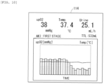
- the display control unit 130 displays various information items on the monitor 114. Specifically, as illustrated in Fig. 10 , the display control unit 130, for example, displays the oxygen partial pressure, the temperature in the bladder, the urinary volume, and the integrated value of the urinary volume on the monitor 114 as a numerical value, and displays a time change in the oxygen partial pressure and a time change in the temperature in the bladder on the monitor 114 in a graph. In addition, in a case where the urinary volume determination control determines that it corresponds to any one of the first stage to the third stage of AKI (Step S22: YES), the display control unit 130 displays the effect on the monitor 114. Furthermore, in a case where the urinary volume determination control determines that it does not correspond to any one of the first stage to the third stage of AKI (Step S22: NO), the display control unit 130 does not display AKI on the monitor 114.
- the oxygen partial pressure is 38 mmHg
- the temperature in the bladder is 37.4°C
- the urinary volume per unit time is 25.1 mL/h
- the integrated urinary volume is 532 ml
- AKI is displayed as the first stage.
- the time change in the oxygen partial pressure is displayed in a bar graph
- the time change in the temperature in the bladder is displayed in a line graph. That is, a horizontal axis indicates time, one vertical axis indicates an oxygen partial pressure (mmHg), and the other vertical axis indicates a temperature (°C).
- a portion which is blacked out is a portion displaying the oxygen partial pressure in the first display format
- a portion which is not blacked out is a portion displaying the oxygen partial pressure in the second display format. That is, in the bar graph, the oxygen partial pressure of the portion which is blacked out, is the oxygen partial pressure in the urine when the flow velocity V of the urine is greater than or equal to the reference flow velocity V0, and the oxygen partial pressure of the portion which is not blacked out, is the oxygen partial pressure in the urine when the flow velocity V of the urine is less than the reference flow velocity V0.
- the first display format and the second display format of the oxygen partial pressure are not limited to the example of Fig. 10 .
- the first display format may be displayed in a state of not being blacked out
- the second display format may be displayed in a state of being blacked out.
- the display control unit 130 may display the time change in the oxygen partial pressure on the monitor 114 in a line graph.
- a thick line portion is a portion displaying the oxygen partial pressure in the first display format
- a thin line portion is a portion displaying the oxygen partial pressure in the second display format.
- the first display format may be displayed with a thin line
- the second display format may be displayed with a thick line.
- a portion of which a lower side from a line segment indicating the value of the oxygen partial pressure is blacked out may be set to the first display format of the oxygen partial pressure, and a portion of which the lower side is not blacked out, may be set to the second display format of the oxygen partial pressure.
- the first display format may be displayed in a state where the lower side is not blacked out
- the second display format may be displayed in a state where the lower side is blacked out.
- Step S12 determines whether or not the stop button 112 is operated. In a case where the stop button 112 is not operated (Step S12: NO), the process proceeds to processing after Step S5. On the other hand, in a case where the stop button 112 is operated (Step S12: YES), the control unit 116 stops the operation of the oxygen measurement (Step S13). That is, the emission of the excitation light of the light emitting portion 104 is stopped. In this stage, oxygen measurement processing of the current flowchart is ended.
- the oxygen measurement device 10A includes the urethral catheter 18a including the flexible hollow shaft 22a, and the oxygen sensor 20a including the oxygen sensor main body 50a capable of detecting the oxygen in the urine.
- the urine introduction port 28a allowing the urine in the bladder 140 to flow therein, and the urinary passage 74 communicated with the urine introduction port 28a to circulate the urine, are disposed in the shaft 22a.
- the oxygen sensor 20a is disposed in the urethral catheter 18a such that the oxygen sensor main body 50a is in contact with the urine circulated in the urinary passage 74. Accordingly, the oxygen sensor main body 50a can be in contact with the urine circulated in the urinary passage 74, and thus, it is possible to accurately and reliably measure the oxygen in new urine which is discharged from the kidney to the outside of the body through the bladder 140.
- the oxygen sensor 20a includes the oxygen sensor main body 50a including the fluorescent body 56, and the substrate 54a coated with the fluorescent body 56, and the optical fiber 58 formed separately from the oxygen sensor main body 50a.
- the oxygen sensor main body 50a is fixed to the urethral catheter 18a such that at least a part of the fluorescent body 56 is in contact with the urine in the urinary passage 74, and the optical fiber 58 is fixed to the urethral catheter 18a in a state where the distal end surface 58a of the optical fiber 58 is positioned with respect to the fluorescent body 56 such that the fluorescent body 56 can be irradiated with the excitation light, and the fluorescence from the fluorescent body 56 can be received. Accordingly, the oxygen sensor main body 50a including the fluorescent body 56 and the optical fiber 58 are separately manufactured, and are incorporated in the urethral catheter 18a, and thus, it is possible to measure the oxygen in the urine.
- the distal end opening portion 34 of the lumen 30 configuring the urinary passage 74 is formed on the distal end of the shaft 22a.
- the urethral catheter 18a includes the blocking portion 23a which is fitted into the distal end opening portion 34, and the oxygen sensor main body 50a is fixed to the blocking portion 23a.
- the blocking portion 23a to which the oxygen sensor main body 50a is fixed is fitted into the distal end opening portion 34 from the distal end side of the shaft 22a, and thus, it is possible to accurately, easily, and reliably incorporate the oxygen sensor main body 50a with respect to the shaft 22a.
- the optical fiber 58 is fixed to the shaft 22a such that the distal end surface 58a of the optical fiber 58 is positioned in the urinary passage 74 and faces the fluorescent body 56. Accordingly, it is possible to efficiently irradiate the fluorescent body 56 with the excitation light from the optical fiber 58, and to efficiently receive the fluorescence from the fluorescent body 56 by the optical fiber 58.
- the adhesive agent 66 can be injected from the through hole 68 formed on the outer surface of the shaft 22a at the time of fixing the optical fiber 58, and thus, it is possible to improve assemblability, and to prevent the distal end surface 58a of the optical fiber 58 from being contaminated by the adhesive agent 66.
- the substrate 54a of the oxygen sensor main body 50a may have a width dimension narrower than the width dimension of the protruding portion 38, and the latch groove 200 into which the substrate 54a bent approximately into a U-shape, is fitted, may be formed in the protruding portion 38 of a blocking portion 23b.
- the substrate 54a is formed into the shape of a band.
- the latch groove 200 is positioned in the center of a width direction of the protruding portion 38, and allows each of the side surfaces 38b to extend in a protruding direction of the protruding portion 38, and the protruding end surface 38a to extend over the entire length in the height direction. According to such a configuration, the material of the substrate 54a and the fluorescent body 56 can be reduced, and thus, it is possible to reduce the manufacturing cost of the oxygen sensor main body 50a.
- oxygen measurement devices 10B to 10K according to a first modification example to a tenth modification example will be described.
- the oxygen measurement device 10B according to the first modification example will be described. Furthermore, in the oxygen measurement device 10B according to the first modification example, the same reference numerals will be applied to the same constituents as those of the oxygen measurement device 10A described above, and the detailed description thereof will be omitted.
- a urethral catheter 18b is provided in the oxygen measurement device 10B according to the first modification example.
- a sensor lumen 202 in which the optical fiber 58 is provided, is formed in a wall portion of a shaft 22b of the urethral catheter 18b. That is, a partition wall 204 is disposed between the urine introduction lumen 42 and the sensor lumen 202.
- a gap S through which the urine can be circulated, is disposed between a distal end surface of the partition wall 204 and the fluorescent body 56.
- the optical fiber 58 is fixed to the shaft 22b by the adhesive agent 66 which is filled in the sensor lumen 202 to seal the through hole 68 formed on the outer surface of the distal end portion of the shaft 22b.
- the through hole 68 is formed in a portion positioned between two urine introduction ports 28a on the outer circumference surface of the shaft 22b.
- the optical fiber 58 is provided in the sensor lumen 202, and thus, it is possible to prevent the circulation of the urine in the urinary passage 74 from being inhibited by the optical fiber 58. Accordingly, it is possible to smoothly circulate the urine in the urinary passage 74.
- the oxygen measurement device 10C according to the second modification example includes a urethral catheter 18c and an oxygen sensor 20b.
- the urethral catheter 18c includes a shaft 22c and a blocking portion 23c.
- An arrangement hole 206 in which the optical fiber 58 is provided, is formed in the protruding portion 38 of the blocking portion 23c.
- the partition wall 204 extends to the position of the protruding end surface 38a of the protruding portion 38.
- a substrate 54b of an oxygen sensor main body 50b is attached to the protruding end surface 38a of the protruding portion 38 to cover the arrangement hole 206 from the proximal end side, and to allow the fluorescent body 56 to be in contact with the urine in the urinary passage 74.
- the substrate 54b is configured to be capable of transmitting the excitation light from the optical fiber 58 and the fluorescence from the fluorescent body 56.
- the fluorescent body 56 is positioned on the distal end side from the urine introduction port 28a.
- the optical fiber 58 is fixed to the urethral catheter 18c in a state of being turned back to the proximal end side at 180° on the distal end side from the urinary passage 74 such that the distal end surface 58a of the optical fiber 58 is positioned on a side opposite from the urinary passage 74 sandwiching the oxygen sensor main body 50b. That is, a turned-back portion of the optical fiber 58 is disposed in the arrangement hole 206 of the protruding portion 38.
- the optical fiber 58 is fixed to the shaft 22c and the blocking portion 23c by injecting the adhesive agent 66 into the arrangement hole 206 from the outside of the shaft 22c through the through hole 68 which is formed on the outer surface of the shaft 22c.
- the distal end surface 58a of the optical fiber 58 is in contact with a rear surface of the substrate 54b on a side opposite to a surface coated with the fluorescent body 56.
- the distal end surface 58a of the optical fiber 58 may be close to the rear surface of the substrate 54b.
- the assembly of the oxygen sensor 20b with respect to the urethral catheter 18c will be described. Furthermore, in an initial state, the substrate 54b coated with the fluorescent body 56, is fixed to the protruding end surface 38a of the protruding portion 38 by an adhesive agent (not illustrated) or the like.
- an adhesive agent not illustrated
- a distal end of the optical fiber 58 is drawn out in the distal end direction from the distal end opening portion 34 of the shaft 22c. Then, the distal end portion of the optical fiber 58 is disposed in the arrangement hole 206 of the protruding portion 38 in a state of being turned back at 180°.
- the distal end surface 58a of the optical fiber 58 is in contact with or close to the rear surface of the substrate 54b. Subsequently, the distal end surface 58a of the shaft 22c, and a wall surface configuring the distal end opening portion 34 are coated with the adhesive agent 40, and thus, the protruding portion 38 is fitted into the distal end opening portion 34. At this time, a portion of the optical fiber 58, which is drawn out in the distal end direction, is pushed by the blocking portion 23c, and is pushed back in the proximal end direction.
- the adhesive agent 66 is injected into the arrangement hole 206 from the outside of the shaft 22c through the through hole 68, and thus, the optical fiber 58 is fixed to the shaft 22c and the blocking portion 23c. Accordingly, it is possible to accurately position the fluorescent body 56 and the distal end surface 58a of the optical fiber 58.
- the optical fiber 58 is fixed to the urethral catheter 18c in the state of being turned back on the distal end side from the urinary passage 74 such that the distal end surface 58a of the optical fiber 58 is positioned on the side opposite to the urinary passage 74 sandwiching the oxygen sensor main body 50b.
- the base portion is configured to be capable of transmitting the excitation light from the optical fiber 58 and the fluorescence from the fluorescent body 56. For this reason, it is possible to improve assemblability and accuracy, and to measure the oxygen in the urine while preventing the distal end surface 58a of the optical fiber 58 from being contaminated due to the contact with the urine.
- the distal end surface 58a of the optical fiber 58 is in contact with the surface of the substrate 54b (the base portion) on a side opposite to the surface coated with the fluorescent body 56. Accordingly, it is possible to reliably bring the fluorescent body 56 into contact with the urine, to efficiently irradiate the fluorescent body 56 with the excitation light from the optical fiber 58, and to efficiently receive the fluorescence from the fluorescent body 56 by the optical fiber 58.
- the arrangement hole 206 in which the turned-back portion of the optical fiber 58 is provided is formed in the blocking portion 23c. Accordingly, it is possible to dispose the optical fiber 58 in a state of being easily turned back on the distal end side of the urinary passage 74.
- the oxygen measurement device 10D according to the third modification example will be described. Furthermore, in the oxygen measurement device 10D according to the third modification example, the same reference numerals will be applied to the same constituents as those of the oxygen measurement device 10C according to the second modification example, and the detailed description thereof will be omitted.
- the oxygen measurement device 10D includes a urethral catheter 18d and an oxygen sensor 20c.
- the urethral catheter 18d includes a shaft 22d and a blocking portion 23d.
- the blocking portion 23d includes a distal end bulging portion 208 and a protruding portion 210.
- the first hole portion 212 includes a first opening portion 212a and a second opening portion 212b which are opened on a proximal end surface 208a of the distal end bulging portion 208, and a third opening portion 212c which is opened on the most-distal end of the distal end bulging portion 208.
- the first opening portion 212a is communicated with the sensor lumen 202.
- the second opening portion 212b is positioned approximately in the center of the proximal end surface.
- the slit 214 extends from the first opening portion 212a to the third opening portion 212c, along the shaft line direction.
- the second hole portion 216 linearly extends from the second opening portion 212b to the bottom of the concave portion 215.
- the first hole portion 212 and the second hole portion 216 are communicated with each other to function as an arrangement hole 217 in which the optical fiber 58 is disposed.
- the oxygen sensor main body 50c includes a support portion 218 fixed to the blocking portion 23d.
- the substrate 54b is fixed to the support portion 218.
- the support portion 218 is formed into the shape of a rectangular plate, and is fixed to the protruding portion 210 in a state of being provided in the concave portion 215.
- a positioning hole 220 (a positioning portion) positioning the distal end of the optical fiber 58, is disposed in the support portion 218.
- the fluorescent body 56 is positioned on the distal end side from the urine introduction port 28b.
- the optical fiber 58 is held in the blocking portion 23d in a state of being disposed in the arrangement hole 217. That is, the optical fiber 58 is held in the blocking portion 23d in a state of being disposed in the first opening portion 212a, the first hole portion 212, the second opening portion 212b, and the second hole portion 216.
- the optical fiber 58 is turned back on the proximal end side at 180° in the first hole portion 212 on the distal end side from the urinary passage 74.
- the slit 214 and the third opening portion 212c are formed in the blocking portion 23d, and thus, it is possible to easily bend the blocking portion 23d when the optical fiber 58 is turned back in the first hole portion 212.
- the distal end surface 58a of the optical fiber 58 is in contact with the rear surface of the substrate 54b.
- the distal end surface 58a of the optical fiber 58 may be close to the substrate 54b.
- the urine introduction port 28b is formed such that an opening width along a circumferential direction increases towards the distal end direction of the shaft 22d.
- the assembly of the oxygen sensor 20c with respect to the urethral catheter 18d will be described. Furthermore, in an initial state, the substrate 54b coated with the fluorescent body 56 is fixed to the support portion 218, and the support portion 218 is fixed into the concave portion 215 of the protruding portion 210 by an adhesive agent (not illustrated) or the like. In this modification example, in a state where the optical fiber 58 is inserted into the sensor lumen 202, the distal end of the optical fiber 58 is drawn out in the distal end direction from the distal end opening portion 34 of the shaft 22d.
- the blocking portion 23d is held such that the third opening portion 212c is directed towards the distal end of the optical fiber 58, the distal end of the optical fiber 58 is inserted into the blocking portion 23d from the third opening portion 212c to reach the second hole portion 216 through the second opening portion 212b, the distal end of the optical fiber 58 is fitted into the positioning hole 220 such that the distal end surface 58a is disposed to be in contact with or in the vicinity of the rear surface of the substrate 54b, and a wall surface configuring the second hole portion 216 and the optical fiber 58 are coated with an adhesive agent (not illustrated) and are fixed together.
- an adhesive agent not illustrated
- the blocking portion 23d is held, the optical fiber 58 is reversed by 180° while confirming that the optical fiber 58 is disposed in the arrangement hole 217 while expanding the slit 214, the optical fiber 58 is disposed in the first opening portion 212a through the first hole portion 212, and the proximal end surface 208a of the blocking portion 23d faces the distal end surface 58a of the shaft 22d.
- the distal end surface 58a of the shaft 22d and the wall surface configuring the distal end opening portion 34 are coated with the adhesive agent 40, and thus, the protruding portion 210 is fitted into the distal end opening portion 34. Accordingly, the blocking portion 23d is fixed to the shaft 22d, and thus, the oxygen sensor main body 50c which is fixed to the blocking portion 23d, is fixed to the shaft 22d. At this time, a portion of the optical fiber 58, which is drawn out in the distal end direction, is pushed by the shaft 22d, is pushed back in the distal end direction, and is contained in the arrangement hole 217.
- the adhesive agent 66 is injected into the sensor lumen 202 from the outside of the shaft 22d through the through hole 68, and thus, the optical fiber 58 is fixed to the shaft 22d.
- an adhesive agent (not illustrated) is injected into the arrangement hole 217 from the third opening portion 212c until the third opening portion 212c and the slit 214 are filled with the adhesive agent, and the optical fiber 58 is fixed to the blocking portion 23d. Accordingly, it is possible to improve assemblability, and to accurately position the fluorescent body 56 and the distal end surface 58a of the optical fiber 58.
- the distal end of the optical fiber 58 is fitted into the positioning hole 220 of the support portion 218 from the third opening portion 212c through the first hole portion 212, the second opening portion 212b, and the second hole portion 216, in a state where the optical fiber 58 is turned back at 180°, as another assembling method. Subsequently, a portion of the optical fiber 58 on the outside of the distal end bulging portion 208 is pushed towards the slit 214 in a state of being along the slit 214. Then, the width of the slit 214 increases, and the optical fiber 58 is disposed in the first hole portion 212 and the first opening portion 212a.
- the distal end surface 58a of the shaft 22d and the wall surface configuring the distal end opening portion 34 are coated with the adhesive agent 40, and the protruding portion 210 is fitted into the distal end opening portion 34. Accordingly, the blocking portion 23d is fixed to the shaft 22d, and thus, the oxygen sensor main body 50c which is fixed to the blocking portion 23d, is fixed to the shaft 22d. At this time, a portion of the optical fiber 58, which is drawn out in the distal end direction, is pushed by the blocking portion 23d, and is pushed back in the proximal end direction.
- the adhesive agent 66 is injected into the sensor lumen 202 from the outside of the shaft 22d through the through hole 68, and thus, the optical fiber 58 is fixed to the shaft 22d.
- an adhesive agent (not illustrated) is injected into the arrangement hole 217 from the third opening portion 212c until the third opening portion 212c and the slit 214 are filled with the adhesive agent, and the optical fiber 58 is fixed to the blocking portion 23d.
- the optical fiber 58 is held in the blocking portion 23d in a state of being disposed in the arrangement hole 217. Accordingly, when the blocking portion 23d is fitted into the distal end opening portion 34 of the shaft 22d, it is possible to accurately assemble the optical fiber 58 with respect to the shaft 22d.
- the oxygen sensor main body 50c includes the support portion 218 fixed to the blocking portion 23d.
- the substrate 54b is fixed to the support portion 218.
- the positioning hole 220 positioning the distal end of the optical fiber 58 is disposed in the support portion 218. For this reason, it is possible to accurately hold a positional relationship between the distal end surface 58a of the optical fiber 58 and the fluorescent body 56.
- the fluorescent body 56 is positioned on the distal end side from the urine introduction port 28b, and the urine introduction port 28b is formed such that the opening width along the circumferential direction increases towards the distal end direction of the shaft 22d. Accordingly, it is possible to efficiently guide the urine introduced into the urinary passage 74 from the urine introduction port 28b, to the fluorescent body 56 which is positioned on the distal end side from the urine introduction port 28b.
- the same effect is obtained according to the same configuration as that of the oxygen measurement devices 10A to 10C described above.
- the urine introduction port 28b of this modification example may be disposed in the oxygen measurement devices 10A to 10C described above.
- the oxygen measurement device 10E according to the fourth modification example includes a urethral catheter 18e and an oxygen sensor 20d.
- the urethral catheter 18e includes a shaft 22e and a blocking portion 23e.
- An oxygen sensor main body 50d of the oxygen sensor 20d is fixed to the shaft 22e such that the fluorescent body 56 is positioned on the proximal end side from the urine introduction port 28a in the urine introduction lumen 42 (the urinary passage 74).
- a substrate 54c (a base portion) of the oxygen sensor main body 50d is configured to be capable of transmitting the light from the optical fiber 58 and the fluorescence from the fluorescent body 56.
- the substrate 54c is configured into the shape of a circular ring, and extends in a direction orthogonal to a shaft line of the shaft 22e such that the fluorescent body 56 is positioned on the distal end side from the substrate 54c. That is, the substrate 54c includes an inner hole 228 through which the urine is circulated.
- the substrate 54c may be formed into the shape of a rectangular ring, insofar as being in the shape of a ring.
- the holding hole 230 is opened on an outer surface of the shaft 22e, and includes a first slit 230a having a size through which the oxygen sensor main body 50d can be inserted into the urinary passage 74 from the outside of the shaft 22e, and a second slit 230b formed in a wall portion 232 between the dilation lumen 32 and the urine introduction lumen 42.
- the first slit 230a extends in a circumferential direction of the shaft 22e at approximately 180°.
- the second slit 230b extends up to the dilation lumen 32.
- a part of the outer edge portion of the substrate 54c is positioned in the dilation lumen 32. Furthermore, the substrate 54c is positioned on the distal end side from the balloon 24. In addition, the distal end surface 58a of the partition wall 204 is in contact with a rear surface of the substrate 54c on a side opposite to a surface in which the fluorescent body 56 is positioned.
- the substrate 54c is fixed to the shaft 22e by the adhesive agent 66 which is injected into the first slit 230a and the second slit 230b.
- the adhesive agent 66 seals a part of the dilation lumen 32, the first slit 230a, and the second slit 230b, and flows into the sensor lumen 202, and thus, the optical fiber 58 is fixed to the shaft 22e.
- the optical fiber 58 is disposed on the proximal end side from the base portion such that the distal end surface 58a of the optical fiber 58 faces the rear surface of the substrate 54c.
- the distal end surface 58a of the optical fiber 58 is in contact with the rear surface of the substrate 54c.
- the distal end surface 58a of the optical fiber 58 may be close to the rear surface of the substrate 54c.
- the optical fiber 58 is inserted into the sensor lumen 202.
- the oxygen sensor main body 50d is pushed to the first slit 230a from the outside of the shaft 22e, in a state where the outer edge portion of the substrate 54c is coated with the adhesive agent 66.
- the oxygen sensor main body 50d is inserted into the second slit 230b, and thus, the oxygen sensor main body 50d is held in the holding hole 230.
- the adhesive agent 66 is injected into the first slit 230a as a through hole, from the outside of the shaft 22e, and thus, the oxygen sensor main body 50d and the optical fiber 58 are fixed to the shaft 22e. Accordingly, it is possible to accurately position the fluorescent body 56 and the distal end surface 58a of the optical fiber 58.
- the fluorescent body 56 is positioned on the proximal end side from the urine introduction port 28a in the urinary passage 74. Accordingly, it is possible to efficiently bring the urine circulated through the urine introduction lumen 42 into contact with the fluorescent body 56.
- the substrate 54c is configured to be capable of transmitting the excitation light from the optical fiber 58 and the fluorescence from the fluorescent body 56, and extends in the direction orthogonal to the shaft line of the shaft 22e such that the fluorescent body 56 is positioned on the distal end side from the substrate 54c.
- the optical fiber 58 is disposed on the proximal end side from the base portion such that the distal end surface 58a of the optical fiber 58 faces the rear surface of the base portion on the side opposite from the surface coated with the fluorescent body 56. Accordingly, it is possible to efficiently bring the urine in the urinary passage 74 into contact with the fluorescent body 56. In addition, it is possible to efficiently irradiate the fluorescent body 56 with the excitation light from the optical fiber 58, and to efficiently receive the fluorescence from the fluorescent body 56 by the optical fiber 58.
- the substrate 54c is configured into the shape of a ring. For this reason, it is possible to smoothly circulate the urine in the urine introduction lumen in a proximal end direction of the shaft 22e through the inner hole of the substrate 54c.
- the holding hole 230 into which the outer edge portion of the base portion is inserted is formed on the wall surface configuring the urine introduction lumen 42. Accordingly, it is possible to hold the substrate 54c in a state where the substrate 54c extends in the direction orthogonal to the shaft line of the shaft 22e, by a simple configuration.
- the holding hole 230 is opened on the outer surface of the shaft 22e, and includes the first slit 230a having a size through which the oxygen sensor main body 50d can be inserted into the urinary passage 74 from the outside of the shaft 22e, and the oxygen sensor main body 50d is fixed to the shaft 22e by the adhesive agent 66 filled to seal the first slit 230a. In this case, it is possible to simply and accurately assemble the oxygen sensor main body 50d from the outside of the shaft 22e.
- the oxygen measurement device 10F according to the fifth modification example includes a urethral catheter 18f and an oxygen sensor 20e.
- the urethral catheter 18f includes a shaft 22f and the blocking portion 23e.
- An oxygen sensor main body 50e of the oxygen sensor 20e is fixed to the shaft 22f such that the fluorescent body 56 is positioned on the proximal end side from the urine introduction port 28a in the urine introduction lumen 42 (the urinary passage 74).
- a substrate 54d (a base portion) of the oxygen sensor main body 50e is configured of glass, polyethylene, or the like, which is capable of transmitting the excitation light from the optical fiber 58 and the fluorescence from the fluorescent body 56.
- the substrate 54d is configured into the shape of a flat plate.
- the oxygen sensor main body 50e includes a support portion 240a which is fixed to the shaft 22f.
- the substrate 54d is fixed to the support portion 240a.
- the support portion 240a is configured of the same material as that of the shaft 22f, or glass, a resin material, or the like, into the shape of a rectangular ring, and has a shape according to the sectional shape of the urine introduction lumen 42. That is, an outer surface of the support portion 240a is in contact with the wall surface configuring the urine introduction lumen 42.
- the support portion 240a is disposed on the proximal end side from the urine introduction port 28a in the urine introduction lumen 42.
- the substrate 54d is fixed to a wall surface configuring an inner hole 241a of the support portion 240a in a state where the substrate 54d extends in a shaft line direction of the shaft 22f. That is, the fluorescent body 56 is positioned in the inner hole 241a of the support portion 240a.
- the support portion 240a includes two convex portions 246 and 248 (a second engagement portion) which are positioned in the shaft 22f by being fitted into two support holes 242 and 244 (a first engagement portion) as a through hole disposed on the wall surface configuring the urine introduction lumen 42.
- Two support holes 242 and 244 are positioned on opposite sides by sandwiching the support portion 240a therebetween.
- the support hole 242 is a through hole which extends up to an outer surface of the shaft 22f to traverse the sensor lumen 202.
- the support hole 244 is a through hole which extends up to the outer surface of the shaft 22f to traverse the dilation lumen 32.
- the convex portions 246 and 248 are semispherical protrusions protruding to the outside from the outer surface of the support portion main body 245.
- a positioning hole 250 (a positioning portion) into which the distal end of the optical fiber 58 is fitted, is disposed in the support portion main body 245 and the convex portion 246.
- the positioning hole 250 is opened on a surface to which the substrate 54d is fixed, in the wall surface configuring the inner hole 241a of the support portion 240a.
- the optical fiber 58 is provided in the sensor lumen 202, the support hole 242, and the positioning hole 250.
- the distal end surface 58a of the optical fiber 58 is in contact with a rear surface of the substrate 54d.
- the distal end surface 58a of the optical fiber 58 may be close to the rear surface of the substrate 54d.
- the support portion 240a and the optical fiber 58 are fixed to the shaft 22f by an adhesive agent 252 filled to seal the support holes 242 and 244.
- the assembly of the oxygen sensor 20e with respect to the urethral catheter 18f will be described. Furthermore, in an initial state, the substrate 54d coated with the fluorescent body 56, is fixed to the support portion 240a by an adhesive agent (not illustrated) or the like.
- the distal end of the optical fiber 58 is drawn out in the distal end direction from the distal end opening portion 34 of the shaft 22f. In such a state, the optical fiber 58 is inserted into the support hole 242.
- the support portion 240a is inserted from the distal end opening portion 34 of the shaft 22f, and the convex portion 246 is fitted into the support hole 242, and the convex portion 248 is fitted into the support hole 244.
- a portion of the optical fiber 58 which is drawn out in the distal end direction, is pushed by the support portion 240a, and is pushed back in the proximal end direction.
- the adhesive agent 252 is injected into each of the support holes 242 and 244 from the outside of the shaft 22f, and thus, the support portion 240a and the optical fiber 58 are fixed to the shaft 22f. Accordingly, it is possible to accurately position the fluorescent body 56 and the distal end surface 58a of the optical fiber 58.
- the protruding portion 38 of the blocking portion 23e is fitted into the distal end opening portion 34 of the shaft 22f.
- the optical fiber 58 may be in a state of being drawn out from the support hole 242 through the sensor lumen 202, the support portion 240a may be inserted from the distal end opening portion 34 of the shaft 22f, the convex portion 246 may be fitted into the support hole 242, and the convex portion 248 may be fitted into the support hole 244, and then, the distal end of the optical fiber 58 is fitted into the positioning hole 250 of the support portion 240a, and the portion of the optical fiber 58, which is drawn out from the support hole 242, may be pushed back in the proximal end direction, as another assembling method.
- the oxygen sensor main body 50e includes the support portion 240a which is fixed to the shaft 22f.
- the substrate 54d is fixed to the support portion 240a, and the positioning hole 250 positioning the distal end of the optical fiber 58, is disposed in the support portion 240a. Accordingly, it is possible to accurately hold a positional relationship between the distal end surface 58a of the optical fiber 58 and the fluorescent body 56.
- the support holes 242 and 244 are disposed on the wall surface configuring the urinary passage 74, and the convex portions 246 and 248 to be positioned in the shaft 22f by being fitted into (engaged with) the support holes 242 and 244, are disposed in the support portion 240a. Accordingly, it is possible to accurately incorporate the oxygen sensor main body 50e in the urinary passage 74.
- the support portion 240a is configured into the shape of a ring, and the fluorescent body 56 is positioned in the inner hole 241a of the support portion 240a. For this reason, it is possible to bring the urine in the urinary passage 74 into contact with the fluorescent body 56 while circulating the urine in the inner hole 241a of the support portion 240a.
- the substrate 54d extends along the shaft line direction of the shaft 22f. Accordingly, it is possible to prevent the circulation of the urine in the inner hole 241a of the support portion 240a from being inhibited by the substrate 54d, compared to a case where the substrate 54d extends along a direction orthogonal to a shaft line of the shaft 22f.
- the first engagement portion is a convex portion which is formed on the wall surface configuring the urine introduction lumen 42
- the second engagement portion is a hole portion formed in the support portion 240a, into which the convex portion is fitted.
- the oxygen measurement device 10G according to the sixth modification example will be described. Furthermore, in the oxygen measurement device 10G according to the sixth modification example, the same reference numerals will be applied to the same constituents as those of the oxygen measurement device 10F according to the fifth modification example, and the detailed description thereof will be omitted. The same applies to the seventh modification example and the eighth modification example described below.
- the oxygen measurement device 10G includes an oxygen sensor 20f.
- a substrate 54e (a base portion) of an oxygen sensor main body 50f configuring the oxygen sensor 20f is configured into the shape of a rectangular ring, extends in a direction orthogonal to the shaft line direction of the shaft 22f, and is disposed in an inner hole 241b of a support portion 240b such that the fluorescent body 56 is positioned on the distal end side.
- a support protrusion 260 which inwardly protrudes and supports a rear surface of the substrate 54e, is disposed on a wall surface configuring the inner hole 241b of the support portion 240b.
- the positioning hole 250 in which the distal end of the optical fiber 58 is fitted into a rear surface side of the substrate 54e, is formed in the support portion 240b.
- the distal end surface 58a of the optical fiber 58 is contact with the rear surface of the substrate 54e.
- the distal end surface 58a of the optical fiber 58 may be close to the rear surface of the substrate 54e.
- the fluorescent body 56 extends in the direction orthogonal to the shaft line of the shaft 22f, and thus, it is possible to efficiently bring the urine introduced into the urine introduction lumen 42 from the urine introduction port 28a, into contact with the fluorescent body 56.
- the same effect is obtained according to the same configuration as that of the oxygen measurement devices 10A to 10F described above.
- the oxygen measurement device 10H according to the seventh modification example includes an oxygen sensor 20g.
- a support portion 240c of an oxygen sensor main body 50g configuring the oxygen sensor 20g is configured of a material which is capable of transmitting the excitation light from the optical fiber 58 and the fluorescence from the fluorescent body 56. Examples of such a material include the same configuration material as that of the substrate 54d.
- the substrate 54d is fixed to a wall surface configuring an inner hole 241c of the support portion 240c in a state where the substrate 54d extends in the shaft line direction of the shaft 22f.
- a convex portion 246a protruding in the sensor lumen 202 is disposed in the support portion 240c, and the positioning hole 250 into which the distal end of the optical fiber 58 is fitted, is formed in the convex portion 246a.
- the distal end surface 58a of the optical fiber 58 is directed towards the distal end direction in a state where the distal end of the optical fiber 58 is fitted into the positioning hole 250. That is, the optical fiber 58 is fitted into the positioning hole 250 in a state where the optical fiber 58 linearly extends from the sensor lumen 202. That is, the fluorescent body 56 is positioned in a direction intersecting with (a direction orthogonal to) a direction directed by the distal end surface 58a of the optical fiber 58.
- the reflection portion 270 for example, can be configured as a mirror in which a plane obtained by obliquely cutting out a part of the convex portion 246a, is coated with a metal film.
- the reflection portion 270 may have any configuration insofar as being capable of reflecting the excitation light from the optical fiber 58 and the fluorescence from the fluorescent body 56.
- the oxygen measurement device 10l according to the eighth modification example includes a urethral catheter 18g and an oxygen sensor 20h.
- the urethral catheter 18g includes a shaft 22g and the blocking portion 23e.
- An oxygen sensor main body 50h of the oxygen sensor 20h is fixed to the shaft 22g such that the fluorescent body 56 is positioned on the proximal end side from the urine introduction port 28a in the urine introduction lumen 42.
- the substrate 54d of the oxygen sensor main body 50h is configured into the shape of a flat plate, extends in a shaft line direction of the shaft 22g, and is fixed to a flat plate support portion 240d such that the fluorescent body 56 is directed inwardly to the urine introduction lumen 42.
- the positioning hole 250 (the positioning portion) into which the distal end of the optical fiber 58 is fitted, is formed in the support portion 240d. The positioning hole 250 is positioned on a rear surface side of the substrate 54d.
- the distal end of the optical fiber 58 is fitted into the positioning hole 250 in a state where the optical fiber 58 is inserted into an insertion hole 280 formed in the partition wall 204.
- a wall surface 280a configuring the insertion hole 280 is sloped in a distal end direction from the sensor lumen 202 side towards the urine introduction lumen 42 side.
- the distal end surface 58a of the optical fiber 58 is in contact with the rear surface of the substrate 54d in a state where the distal end of the optical fiber 58 is fitted into the positioning hole 250.
- the distal end surface 58a of the optical fiber 58 may be close to the rear surface of the substrate 54d.
- the support portion 240d and the optical fiber 58 are fixed to the shaft 22g by the adhesive agent 252 filled to seal the through hole 68 and the insertion hole 280, which are formed on an outer surface of the shaft 22g.
- the assembly of the oxygen sensor 20h with respect to the urethral catheter 18g will be described. Furthermore, in an initial state, the substrate 54d coated with the fluorescent body 56, is fixed to the support portion 240d by an adhesive agent (not illustrated) or the like. In this modification example, in a state where the optical fiber 58 is inserted into the sensor lumen 202, the distal end of the optical fiber 58 is drawn out in the distal end direction from the distal end opening portion 34 of the shaft 22g. In such a state, the optical fiber 58 is inserted into the insertion hole 280.
- the support portion 240d is inserted from the distal end opening portion 34 of the shaft 22g while the optical fiber 58 is pulled back in a proximal end direction, and is brought into contact with the wall surface configuring the urine introduction lumen 42 such that the insertion hole 280 is covered from the urine introduction lumen 42 side.
- the adhesive agent 252 is injected into the sensor lumen 202 and the insertion hole 280 from the outside of the shaft 22g through the through hole 68, and thus, the support portion 240d and the optical fiber 58 are fixed to the shaft 22g. Accordingly, it is possible to accurately position the fluorescent body 56 and the distal end surface 58a of the optical fiber 58.
- the protruding portion 38 of the blocking portion 23e is fitted into the distal end opening portion 34 of the shaft 22g.
- the oxygen sensor 20h may include an oxygen sensor main body 50ha illustrated in Fig. 21A .
- a slope 282 is formed on the distal end of the shaft 22g in the shaft line direction, on a substrate 54f of the oxygen sensor main body 50ha, and a slope 284 is formed on the distal end of the shaft 22g in the shaft line direction, in a support portion 240e.
- Each of the slopes 282 and 284 is sloped in a direction opposite to the sensor lumen 202 (inwardly to the shaft 22g) towards the proximal end direction of the shaft 22g.
- the slope 282 and the slope 284 are flush with each other.
- the fluorescent body 56 is applied to the slope 282, and a surface continuous from the slope 282 in the proximal end direction.
- the distal end of the optical fiber 58 is fitted into the concave portion 286 and the positioning hole 250.
- the distal end surface 58a of the optical fiber 58 is parallel to the slope 282 (the fluorescent body 56 applied to the slope 282), in a state where the distal end of the optical fiber 58 is fitted into the concave portion 286 and the positioning hole 250.
- the sensor lumen 202 extends up to the distal end of the shaft 22g.
- the fluorescent body 56 applied to the slope 282 extends to be sloped inwardly to the shaft 22g towards the proximal end direction of the shaft 22g, and thus, it is possible to efficiently bring the urine in the urine introduction lumen into contact with the fluorescent body 56.
- the oxygen sensor 20h may include an oxygen sensor main body 50hb illustrated in Fig. 21B .
- a protruding portion 288 to be fitted into the insertion hole 280, is disposed in a support portion 240f of the oxygen sensor main body 50hb. In this case, it is possible to easily and accurately position the support portion 240f in the insertion hole 280.
- the through hole 68 may be omitted.
- the adhesive agent 252 is injected from the distal end opening portion of the sensor lumen 202. Accordingly, the sensor lumen 202 and the insertion hole 280 are filed with the adhesive agent 252, and thus, the support portions 240d to 240f and the optical fiber 58 can be fixed to the shaft 22g.
- the oxygen measurement device 10J according to the ninth modification example includes a urethral catheter 18h and an oxygen sensor 300.
- the sensor lumen 202 which is opened in a portion positioned in a proximal end direction of the shaft 22h, in a wall surface configuring a urine introduction port 28c, is formed in a shaft 22h of the urethral catheter 18h.
- the oxygen sensor 300 is configured as a fluorescent oxygen sensor, and includes an oxygen sensor main body 302 capable of detecting the oxygen in the urine, and a transfer portion 304 extending along the shaft 22h in which the oxygen sensor main body 302 is integrally disposed on a distal end. That is, the oxygen sensor main body 302 is integrally disposed on the distal end of the transfer portion 304.
- the transfer portion 304 is configured of an optical fiber, and the oxygen sensor main body 302 is configured by including a fluorescent body.
- the oxygen sensor 300 may be configured as an electrode type oxygen sensor. In this case, the transfer portion 304 is electrically connected to the oxygen sensor main body 302.
- a distal end surface 302a of the oxygen sensor main body 302 is positioned in the urine introduction port 28c.
- an opening width along a circumferential direction of the distal end is greater than an opening width along a circumferential direction of a proximal end.
- the urine introduction port 28c is formed such that an opening width along the circumferential direction increases towards the distal end direction of the shaft 22h.
- the oxygen sensor main body 302 is integrally disposed on (fixed to) the distal end of the transfer portion 304, and thus, it is possible to easily assemble the oxygen sensor 300 with respect to the shaft 22h.
- the oxygen sensor main body 302 is positioned in the urine introduction port 28c. For this reason, it is possible to bring the oxygen sensor main body 302 into contact with the urine flowing from the urine introduction port 28c.
- the transfer portion 304 is provided in the sensor lumen 202, and thus, it is possible to prevent the circulation of the urine in the urinary passage 74 from being inhibited by the transfer portion 304.
- the oxygen sensor main body 302 is positioned on the proximal end of the urine introduction port 28c, that is, a portion having a narrow opening width. For this reason, it is possible to stably measure the oxygen in the urine in a portion of the urine introduction port 28c of which the shape is hardly deformed even in a case of receiving an external force, and to prevent the sensor from being broken due to the deformation. Furthermore, the oxygen sensor main body 302 and the transfer portion 304 may be assembled in the sensor lumen 202 in a state of being separated from each other in advance, may be positioned in or fitted into the sensor lumen 202, and then, may be fixed by injecting an adhesive agent through a through hole (not illustrated).
- the oxygen measurement device 10J may include an oxygen sensor 20i, instead of the oxygen sensor 300.
- the oxygen sensor 20i includes an oxygen sensor main body 50i, a transfer portion 52 (an optical fiber 58), and a support portion 240d supporting the oxygen sensor main body 50i.
- the oxygen sensor main body 50i is formed by applying the fluorescent body 56 onto a front surface of the substrate 54d on a flat plate.
- the support portion 240d is configured of a material having transparency such that the excitation light and the fluorescence can be transmitted, and includes a hollow support portion main body 290 which is disposed in the urine introduction lumen 42, and a set of hollow protruding portions 291 which extend in opposite directions to each other from the support portion main body 290, and are disposed in each of the urine introduction ports 28c.
- the lumen of the support portion main body 290 extends along the shaft line direction of the shaft 22h over the entire length of the support portion main body 290, and is communicated with the lumen of each of the protruding portions 291.
- An outer surface of the protruding portion 291 is in contact with a wall surface configuring the urine introduction port 28c to cover the opening portion on the distal end side of the sensor lumen 202.
- a protruding length of the protruding portion 291 is set to be the same as a length dimension of the urine introduction port 28c along a diameter direction of the shaft 22h (a thickness dimension of the shaft 22h). For this reason, the protruding portion 291 does not protrude to the outside from the urine introduction port 28c.
- a concave portion 292 is formed on the distal end side of the sensor lumen 202, in an inner surface of the protruding portion 291.
- the substrate 54d is fixed to the concave portion 292 by an adhesive agent (not illustrated) or the like in a state of being fitted thereinto, such that the fluorescent body 56 is in contact with the urine circulated through the lumen of the protruding portion 291.
- a positioning concave portion 293 into which the distal end of the optical fiber 58 is fitted into, is formed in a portion covering the sensor lumen 202 in the outer surface of the protruding portion 291 (a side opposite to the concave portion 292).
- the substrate 54d coated with the fluorescent body 56 is fixed to the support portion 240d by an adhesive agent (not illustrated) or the like.
- the distal end of the optical fiber 58 is drawn out from the opening portion of the sensor lumen 202 on the distal end side in the distal end direction, by a fitted length.
- the support portion 240d is inserted from the distal end opening portion 34 of the shaft 22h, and the protruding portion 291 is fitted into the urine introduction port 28c.
- the distal end of the optical fiber 58 is fitted into the positioning concave portion 293 of the support portion 240d.
- the support portion 240d, the optical fiber 58, and the sensor lumen 202 adhere to each other by using an adhesive agent (not illustrated).
- a portion of the optical fiber 58 which is drawn out in the distal end direction, is pushed by the support portion 240d, and is pushed back in the proximal end direction.
- the support portion 240d and the shaft 22h adhere to each other by using an adhesive agent (not illustrated), as necessary. According to such a configuration, the same effect as that of the embodiments described above is obtained.
- the distal end of the optical fiber 58 may be inserted from the distal end opening portion 34 of the shaft 22h in a state of being fitted in advance into the positioning concave portion 293 of the support portion 240d.
- the oxygen measurement device 10K according to the tenth modification example includes a urethral catheter 18i and the oxygen sensor 300.
- the oxygen sensor 300 is the same as that described in the ninth modification example.
- the urine introduction lumen 42 which extends in an axial direction of the shaft 22i, the sensor lumen 202 in which the transfer portion 304 of the oxygen sensor 300 is provided, and a lateral urine introduction lumen 310 which is communicated with the urine introduction lumen 42, and is disposed on the distal end side of the sensor lumen 202, are formed in a shaft 22i of the urethral catheter 18i.
- the lateral urine introduction lumen 310 is positioned on the proximal end side from the urine introduction port 28a.
- the oxygen sensor 300 extends in the lateral urine introduction lumen 310 such that the oxygen sensor main body 302 is positioned in the urine introduction lumen 42.
- the distal end of the oxygen sensor main body 302 is positioned in the vicinity of the proximal end side of the urine introduction port 28a. Furthermore, the distal end of the sensor lumen 202 is filled with an adhesive agent (not illustrated) which seals the sensor lumen 202, and fixes the transfer portion 304 to the shaft 22i.
- the transfer portion 304 is provided in the sensor lumen 202, and thus, it is possible to prevent the circulation of the urine in the urine introduction lumen 42 from being inhibited by the transfer portion 304. Accordingly, it is possible to smoothly circulate the urine in the urine introduction lumen 42. In addition, it is possible to efficiently bring the oxygen sensor main body 302 into contact with the urine in the urine introduction lumen 42.
- the lateral urine introduction lumen 310 may be communicated with distal end of the urine introduction lumen 42. That is, the lateral urine introduction lumen 310 is in the same position as that of the distal end of the urine introduction port 28a, in a shaft line direction of the shaft 22i.
- the transfer portion 304 is turned back on the proximal end side at 180° from the lateral urine introduction lumen 310 towards the urine introduction lumen 42, and thus, the oxygen sensor main body 302 is positioned on the proximal end side of the urine introduction port 28a. Accordingly, it is possible to efficiently bring the oxygen sensor main body 302 into contact with the urine introduced into the urine introduction lumen 42 from the urine introduction port 28a.
- an arrangement hole 312 in which the turned-back portion of the transfer portion 304 is disposed may be formed in the protruding portion 38 of the blocking portion 23e.
- the protruding portion 38 holds the turned-back portion of the transfer portion 304. Accordingly, it is possible to suppress positional displacement of the oxygen sensor main body 302 in the urine introduction lumen 42.
- an oxygen measurement system 12A according to a second embodiment will be described. Furthermore, in the oxygen measurement system 12A according to this embodiment, the same reference numerals will be applied to the same constituents as those of the oxygen measurement system 12 described above, and the detailed description thereof will be omitted.
- the oxygen measurement system 12A illustrated in Fig. 26 is to measure the oxygen partial pressure (the oxygen concentration) in the urine which is discharged into the bladder 140 from the kidney, in order to predict the state of the kidney, and includes an oxygen measurement device 10L, a urine collection bag 14 (a urine collection container), and a monitoring system 16.
- the oxygen measurement device 10L includes a urethral catheter 18j and an oxygen sensor 400a.
- the urethral catheter 18j is a medical device which is indwelt in the living body at the time of being used, and urinates the urine in the bladder 140 to the urine collection bag 14 disposed on the outside of the body.
- the urethral catheter 18j includes a thin and elongated hollow shaft 22j, a balloon 24 disposed in a distal end portion of the shaft 22j, and a hub 26a disposed in a proximal end portion of the shaft 22j.
- the shaft 22j is an elongated tube of which the most-distal end is in the shape of a hemisphere.
- the shaft 22j has suitable flexibility and suitable stiffness such that a distal end portion of the urethral catheter 18j can be smoothly inserted into the bladder 140 through the urethra 144.
- Examples of a configuration material of the shaft 22j include the same material as that of the shaft 22a described above.
- two urine introduction ports 28a allowing the urine in the bladder 140 to flow into the shaft 22j, a urine introduction lumen 402 which extends along a shaft line direction of the shaft 22j, and functions as a urination flow path, a lateral lumen 406 in which the oxygen sensor 400a and a temperature sensor 404 are provided, and the dilation lumen 32 for circulating the dilation fluid in the balloon 24, are formed in the shaft 22j.
- Each of the urine introduction ports 28a is opened in a portion on a distal end side from the balloon 24, in an outer circumference surface of the shaft 22j.
- two urine introduction ports 28a are disposed in positions facing each other (refer to Fig. 27 and Fig. 28B).
- the shape, the size, the position, and the number of urine introduction ports 28a can be arbitrarily set.
- the urine introduction lumen 402 is disposed such that a shaft line Ax of the shaft 22j is positioned in the urine introduction lumen 402. A distal end of the urine introduction lumen 402 is positioned on the distal end side from the urine introduction port 28a in the shaft 22j, and a proximal end of the urine introduction lumen 402 is opened on the proximal end of the shaft 22j. The urine introduction lumen 402 is communicated with the urine introduction port 28a.
- the lateral lumen 406 extends along the shaft line direction of the shaft 22j in parallel with the urine introduction lumen 402.
- a distal end of the lateral lumen 406 is opened on a distal end surface (a hemisphere surface) of the shaft 22j, and a proximal end of the lateral lumen 406 is opened on the proximal end of the shaft 22j.
- an opening portion 426 of the distal end of the lateral lumen 406 is blocked by a blocking member 407.
- a transverse sectional area of the lateral lumen 406 is less than a flow path sectional area of the urine introduction lumen 402.
- a partition wall 408 extending along the urine introduction lumen 402 is disposed between the urine introduction lumen 402 and the lateral lumen 406.
- the urine introduction port 28a is opened on an inner surface of a distal end portion of the lateral lumen 406. That is, the lateral lumen 406 is communicated with the urine introduction port 28a without passing through the urine introduction lumen 402. In other words, the urine introduction port 28a is positioned to straddle both of the urine introduction lumen 402 and the lateral lumen 406. That is, the urine introduction port 28a is disposed such that a center P is positioned on the lateral lumen 406 side from the shaft line Ax of the shaft 22j.
- the proximal end side from the through hole 410 in the lateral lumen 406, functions as a sensor lumen 412 in which the oxygen sensor 400a and the temperature sensor 404 are provided.
- the distal end side from the sensor lumen 412 in the lateral lumen 406, functions as a lateral urine introduction lumen 414 through which the urine flowing from the urine introduction port 28a is circulated.
- the urine introduction lumen 402, the through hole 410, and the lateral urine introduction lumen 414 may be collectively referred to as a urinary passage 416. That is, the urine flowing from the urine introduction port 28a is circulated in the urinary passage 416.
- a region of the urinary passage 416 in which the urine introduction port 28a is positioned may be referred to as a first urinary passage portion 418, and a region on the proximal end side from the through hole 410 in the urinary passage 416, may be referred to as a second urinary passage portion 420.
- the sensor lumen 412 is shorter than the urine introduction lumen 402.
- the oxygen sensor 400a provided in the sensor lumen 412 is configured as a so-called fluorescent oxygen sensor, and includes an oxygen sensor main body 422a (an oxygen probe) capable of detecting the oxygen in the urine, and a transfer portion 424 (an oxygen transfer portion) optically connected to the oxygen sensor main body 422a.
- the oxygen sensor main body 422a includes a glass optical fiber or a plastic optical fiber. In this case, the core of the optical fiber is exposed to a distal end surface of the oxygen sensor main body 422a.
- the oxygen sensor 400a may be configured as an electrode type oxygen sensor 400a.
- the transfer portion 424 is electrically connected to the oxygen sensor main body 422a.
- the transfer portion 424 is not limited to an optical and electrical portion, and may be a magnetic or mechanical portion.
- the oxygen sensor main body 422a is positioned in the lateral urine introduction lumen 414 (the urinary passage 416). Specifically, the oxygen sensor main body 422a is positioned on the proximal end side from the center of the urine introduction port 28a, and is adjacent to a direction orthogonal to the shaft line direction of the shaft 22j with respect to the urine introduction port 28a. That is, the oxygen sensor main body 422a is adjacent to the proximal end side of the urine introduction port 28a. In other words, the oxygen sensor main body 422a is adjacent to the through hole 410 in the direction orthogonal to the shaft line direction of the shaft 22j. That is, the oxygen sensor main body 422a is not exposed to the outside of the shaft 22j.
- the transfer portion 424 is a cable for optically connecting the oxygen sensor main body 422a and the monitoring system 16 together.
- the transfer portion 424 is optically connected to the oxygen sensor main body 422a through the opening portion 426 of the sensor lumen 412 on the distal end side.
- the opening portion 426 of the sensor lumen 412 is directed towards the shaft line direction (the distal end side) of the shaft 22j.
- an opening area of the opening portion 426 of the sensor lumen 412 is less than an opening area of the urine introduction port 28a.
- the opening portion 426 of the sensor lumen 412 is positioned in the direction orthogonal to the shaft line direction of the shaft 22j with respect to the urine introduction port 28a.
- the temperature sensor 404 provided in the sensor lumen 412 includes a temperature sensor main body 428 (a temperature probe) for detecting the temperature of the urine circulated in the urinary passage 416, and a transfer portion 430 (a temperature transfer portion) electrically connected to the temperature sensor main body 428.
- the temperature sensor main body 428 is positioned between the oxygen sensor main body 422a and the balloon 24. That is, the temperature sensor main body 428 is positioned in the bladder 140 at the time of using the urethral catheter 18j.
- the transfer portion 430 is a cable for electrically connecting the temperature sensor main body 428 and the monitoring system 16 together. The transfer portion 430 is juxtaposed with the transfer portion 424 in the sensor lumen 412.
- the position of the temperature sensor main body 428 can be arbitrarily set.
- the temperature sensor main body 428 may be adjacent to the oxygen sensor main body 422a in the direction orthogonal to the shaft line direction of the shaft 22j. That is, the temperature sensor main body 428 may be positioned in the urinary passage 416.
- the transfer portion 424 and the transfer portion 430 may be integrated into one cable on the inside and the outside of the sensor lumen 412. In this case, it is possible to simplify the wiring of the transfer portion 424 and the transfer portion 430.
- a fixing portion 432a (a distal end side fixing portion) for fixing the oxygen sensor 400a and the temperature sensor 404 to the inner surface configuring the sensor lumen 412, is disposed in the sensor lumen 412.
- the fixing portion 432a is disposed in a distal end portion of the sensor lumen 412.
- the fixing portion 432a is liquid-tightly in contact with the inner surface of the sensor lumen 412 such that the flow of the urine from the urinary passage 416 to the proximal end side from the fixing portion 432a in the sensor lumen 412 is inhibited.
- the fixing portion 432a is configured of a material having flexibility, liquid-tightly inserts a distal end portion of the transfer portion 424 into the insertion hole 434 of the fixing portion 432a, and is liquid-tightly fitted into the distal end portion of the sensor lumen 412 in a state where the temperature sensor main body 428 and a distal end portion of the transfer portion 430 are inserted into a hole 436 of the fixing portion 432a.
- a distal end of the insertion hole 434 is positioned in the vicinity of the urine introduction port 28a and the oxygen sensor main body 422a.
- the fixing portion 432a is configured of the same material as that of the shaft 22j.
- the same material indicates silicone or an adhesive agent containing silicone.
- the fixing portion 432a may be fixed to the inner surface configuring the sensor lumen 412 by an adhesive agent.
- a flow path sectional area of the first urinary passage portion 418 (a transverse sectional area orthogonal to the shaft line direction of the shaft 22j) is greater than a flow path sectional area of the second urinary passage portion 420 (a transverse sectional area) (refer to Fig. 29A and Fig. 29B ).
- the dilation lumen 32 is disposed in a wall portion on a side opposite to the lateral lumen 406 with respect to the urine introduction lumen 402.
- the distal end side of the dilation lumen 32 is communicated with the balloon 24, and the proximal end of the dilation lumen 32 is opened on the proximal end of the shaft 22j.
- the hub 26a is integrally molded into the shape of a hollow, by a resin material.
- the urination port 70, the balloon dilation port 72, and a port 438 for disposing a sensor, are disposed in the hub 26a.
- the transfer portion 424 and the transfer portion 430 are inserted into the port 438 for disposing a sensor.
- the oxygen transfer portion 424 and the transfer portion 430 are electrically and/or optically connected to a transfer cable 441 through a connecter 439 on the outside of the hub 26a (refer to Fig. 26 ).
- the transfer cable 441 is electrically and/or optically connected to the monitor main body portion 94.
- the oxygen sensor main body 422a is positioned in the urinary passage 416. For this reason, it is possible to bring the oxygen sensor main body 422a into contact with the urine circulated in the urinary passage 416. Accordingly, it is possible to accurately and reliably measure oxygen in new urine which is discharged from the kidney to the outside of the body through the urethral catheter 18j, through the bladder 140, but not the urine continuously remaining in the bladder 140.
- the displacement of the oxygen sensor main body 422a with respect to the shaft 22j can be suppressed by the fixing portion 432a, and thus, it is possible to improve a measurement accuracy of the oxygen sensor 400a.
- the transfer portion 424 and the transfer portion 430 are provided in the sensor lumen 412, and thus, it is possible to prevent the circulation of the urine in the urinary passage 416 from being inhibited by the transfer portion 424 and the transfer portion 430. Accordingly, it is possible to smoothly circulate (urinate) the urine in the urinary passage 416.
- a distal end portion of the oxygen sensor 400a (an end portion of the transfer portion 424 on the oxygen sensor main body 422a side) is fixed to the inner surface configuring the sensor lumen 412 by the fixing portion 432a, and thus, it is possible to efficiently suppress the displacement of the oxygen sensor main body 422a with respect to the shaft 22j. Accordingly, it is possible to improve the measurement accuracy of the oxygen sensor 400a.
- a distal end portion of the temperature sensor 404 is fixed to the inner surface configuring the sensor lumen 412 by the fixing portion 432a, and thus, it is possible to efficiently suppress the displacement of the temperature sensor main body 428 with respect to the shaft 22j. Accordingly, it is possible to improve a measurement accuracy of the temperature sensor 404.
- the fixing portion 432a inhibits the flow of the urine from the urinary passage 416 to the proximal end side from the fixing portion 432a in the sensor lumen 412.
- the fixing portion 432a is disposed such that the distal end portion of the sensor lumen 412 is sealed in a state where the transfer portion 424 is inserted thereinto. Accordingly, it is possible to efficiently circulate the urine in the urinary passage 416.
- the periphery of the oxygen sensor main body 422a can be filled with the urine, and thus, it is possible to reliably bring the urine circulated in the urinary passage 416 into contact with the oxygen sensor main body 422a.
- the fixing portion 432a is configured of the material having flexibility, and thus, it is possible to smoothly insert the shaft 22j into the bladder 140.
- the fixing portion 432a is positioned in the sensor lumen 412, and thus, it is possible to prevent the circulation of the urine in the urinary passage 416 from being inhibited by the fixing portion 432a.
- the flow path sectional area of the urinary passage 416 is greater than the transverse sectional area of the sensor lumen 412, and thus, it is possible to more smoothly circulate the urine in the urinary passage 416.
- the urinary passage 416 extends along the shaft line direction of the shaft 22j to be parallel to the sensor lumen 412, and thus, it is possible to make a shape change and a stiffness change in a longitudinal direction of the shaft 22j comparatively small. Accordingly, when the shaft 22j is inserted into the bladder 140, the shaft 22j can be prevented from being buckled or the urinary passage 416 can be prevented from being blocked, and thus, it is possible to stably circulate the urine in the urinary passage 416.
- the sensor lumen 412 includes the opening portion 426 for exposing the oxygen sensor main body 422a into the urinary passage 416. For this reason, it is possible to provide the oxygen sensor main body 422a in the urinary passage 416 while providing the transfer portion 424 in the sensor lumen 412.
- the opening portion 426 of the sensor lumen 412 on the distal end side is directed towards the shaft line direction of the shaft 22j, and thus, it is possible to position the oxygen sensor main body 422a in the urinary passage 416 without bending the transfer portion 424.
- the flow path sectional area of the first urinary passage portion 418 is larger than the flow path sectional area of the second urinary passage portion 420, and thus, it is possible to allow the urine in the bladder 140 to efficiently flow into the first urinary passage portion 418 from the urine introduction port 28a.
- the oxygen sensor main body 422a is positioned in the first urinary passage portion 418, and thus, it is possible to reliably bring the urine flowing into the first urinary passage portion 418 from the bladder 140 through the urine introduction port 28a into contact with the oxygen sensor main body 422a.
- the distal end of the insertion hole 434 of the fixing portion 432a is positioned in the vicinity of the urine introduction port 28a, and thus, it is possible to easily position the oxygen sensor main body 422a in the vicinity of the urine introduction port 28a.
- the oxygen sensor main body 422a is adjacent to the urine introduction port 28a, and thus, it is possible to reliably bring the urine flowing into the urinary passage 416 from the urine introduction port 28a into contact with the oxygen sensor main body 422a.
- the oxygen sensor main body 422a is adjacent to the proximal end side of the urine introduction port 28a (not positioned in the urine introduction port 28a), and thus, even in a case where the shaft 22j is buckled in the position of the urine introduction port 28a, it is possible to prevent the oxygen sensor main body 422a from being broken.
- the oxygen sensor main body 422a is positioned in the direction orthogonal to the shaft line direction of the shaft 22j with respect to the urine introduction port 28a, and thus, it is possible to efficiently bring the urine flowing into the urinary passage 416 from the urine introduction port 28a into contact with the oxygen sensor main body 422a.
- the oxygen sensor main body 422a is positioned on the distal end side from the balloon 24, and thus, it is possible to position the oxygen sensor main body 422a in the bladder 140. Accordingly, it is possible to detect the oxygen in the urine in a comparatively stable environment (an environment in which a temperature change or the like is comparatively small).
- the shaft 22j can be held with respect to the bladder 140 by the balloon 24, and thus, it is possible to suppress the displacement of the oxygen sensor main body 422a in the bladder 140.
- the center P of the urine introduction port 28a is positioned on the sensor lumen 412 from the shaft line Ax of the shaft 22j, and thus, it is possible to easily position the oxygen sensor main body 422a to be adjacent to the urine introduction port 28a.
- the urine introduction port 28a is disposed in a portion of the shaft 22j, which is positioned on the distal end side from the sensor lumen 412, and thus, it is possible to reliably bring the urine flowing into the urinary passage 416 from the bladder 140 through the urine introduction port 28a into contact with the oxygen sensor main body 422a.
- the oxygen measurement system 12A may include oxygen measurement devices 10La to 10Lt described below, instead of the oxygen measurement device 10L. Furthermore, in the oxygen measurement devices 10La to 10Lt, the same reference numerals will be applied to the same constituents as those of the oxygen measurement device 10L described above, and the detailed description thereof will be omitted. Furthermore, in the oxygen measurement devices 10La to 10Lt, actions and effects the same as or similar to those of the oxygen measurement device 10La, can be obtained with respect to the portions common to oxygen measurement device 10L.
- a fixing portion 440 (a proximal end side fixing portion) is disposed on a proximal end portion of the sensor lumen 412, in a shaft 22ja of a urethral catheter 18ja configuring the oxygen measurement device 10La illustrated in Fig. 30 .
- the fixing portion 440 is configured of a material having flexibility, inserts a proximal end portion of the transfer portion 424 into the insertion hole 442 of the fixing portion 440, and is fitted into the proximal end portion of the sensor lumen 412 in a state where a proximal end portion of the transfer portion 430 is inserted into an insertion hole 444 of the fixing portion 440.
- the fixing portion 440 may be configured to be more flexible than the fixing portion 432a positioned on the distal end side. The expansion and contraction of the urethral catheter 18ja are absorbed, and thus, it is possible to prevent the oxygen sensor 400a from being broken.
- a fixing portion 432b is disposed in a shaft 22jb of a urethral catheter 18jb configuring the oxygen measurement device 10Lb illustrated in Fig. 31 , instead of the fixing portion 432a.
- the fixing portion 432b extends over the entire length to seal the entire sensor lumen 412.
- the fixing portion 432b is configured of a material having flexibility, inserts the transfer portion 424 into an insertion hole 448 of the fixing portion 432b, and is fixed to the wall surface configuring the sensor lumen 412 in a state where the transfer portion 430 is inserted into a hole 450 of the fixing portion 432b. According to such a configuration, it is possible to effectively suppress the displacement of the oxygen sensor main body 422a and the temperature sensor main body 428 with respect to the shaft 22jb.
- the partition wall 408 (refer to Fig. 27 ) described above is omitted. That is, the lateral lumen 406 as illustrated in Fig. 27 is not disposed, but a urine introduction lumen 452 is disposed in the shaft 22jc. In this case, the urine introduction lumen 452 functions as a urinary passage 454.
- the oxygen sensor 400a and the temperature sensor 404 are provided in the urinary passage 454.
- the fixing portion 432c is separated from an inner surface of the urinary passage 454, which faces the fixing portion 432c.
- the fixing portion 432c is separated from a portion facing a portion of the inner surface configuring the urinary passage 454, which is in contact with the fixing portion 432c. Accordingly, the circulation of the urine in the urinary passage 454 can be prevented from being inhibited by the fixing portion 432c, and thus, it is possible to smoothly circulate the urine in the urinary passage 454.
- a fixing portion 432d is disposed in a shaft 22jd of a urethral catheter 18jd configuring the oxygen measurement device 10Ld illustrated in Fig. 34 , instead of the fixing portion 432c of the urethral catheter 18jc illustrated in Fig. 32 .
- the fixing portion 432d is disposed to cover the transfer portion 424 and the temperature sensor 404 in the urinary passage 454. In this case, it is possible to more smoothly circulate the urine in the urinary passage 454.
- the flow path sectional area of the second urinary passage portion 420 gradually increases towards the proximal end side. According to such a configuration, it is possible to smoothly circulate the urine in the second urinary passage portion 420 towards the proximal end of the shaft 22je.
- the flow path sectional area of the second urinary passage portion 420 may gradually increase towards the proximal end side. That is, in the second urinary passage portion 420, a flow path sectional area on the proximal end side may be greater than a flow path sectional area on the distal end side.
- a concave portion 462 is disposed on a surface of the fixing portion 432a, which is exposed to the urinary passage 416 side, and the oxygen sensor main body 422a is positioned in the concave portion 462.
- the blocking member 407 described above is omitted. For this reason, the urine in the bladder 140 flows from an opening portion 464 of the lateral lumen 406 on the distal end side.
- the oxygen sensor main body 422a may be positioned on the outside of the concave portion 462 in the urinary passage 416.
- An oxygen sensor 400b and a urine introduction port 28d are disposed in a shaft 22jg of a urethral catheter 18jg configuring the oxygen measurement device 10Lg illustrated in Fig. 36B , instead of the oxygen sensor 400a and the urine introduction port 28a illustrated in Fig. 36A .
- An oxygen sensor main body 422b of the oxygen sensor 400b extends to the distal end side from the urine introduction port 28d.
- a urine introduction port 28d is different from the urine introduction port 28a described above in that the urine introduction port 28d is in the shape of a rectangle. According to such a configuration, it is possible to effectively suppress the displacement of the oxygen sensor main body 422b with respect to the shaft 22jg.
- a urine introduction port 28e is disposed in a shaft 22jh of a urethral catheter 18jh configuring the oxygen measurement device 10Lh illustrated in Fig. 37A , instead of the urine introduction port 28a illustrated in Fig. 36A .
- the urine introduction port 28e is communicated only with the urine introduction lumen 402, and does not straddle the lateral lumen 406.
- the urine introduction lumen 402 and the lateral lumen 406 are not communicated with each other. For this reason, the entire urine introduction lumen 402 functions as a urinary passage 474, and the urine does not flow into the distal end side from the sensor lumen 412 in the lateral lumen 406.
- an opening portion 476 for positioning the oxygen sensor main body 422a in the urinary passage 474 penetrates through the partition wall 408. That is, the opening portion 476 is directed towards a direction orthogonal to a shaft line direction of the shaft 22jh.
- the transfer portion 424 is bent to the urinary passage 474 side on the distal end side, and extends to the urinary passage 474 through the opening portion 476.
- the oxygen sensor main body 422a is positioned on the proximal end side from the urine introduction port 28e.
- a fixing portion 432f is disposed in the shaft 22jh, instead of the fixing portion 432a illustrated in Fig. 36A .
- the fixing portion 432f is disposed to seal the distal end side of the lateral lumen 406 (the distal end side from the sensor lumen 412), and to seal the opening portion 476. Furthermore, the fixing portion 432f fixes the distal end portion of the transfer portion 424 and the distal end portion of the temperature sensor 404 to the inner surface configuring the sensor lumen 412.
- the oxygen sensor main body 422a is positioned on the proximal end side from the urine introduction port 28e, and thus, even in a case where the shaft 22jh is buckled in the position of the urine introduction port 28e, it is possible to reliably prevent the oxygen sensor main body 422a from being broken. In addition, it is possible to reliably bring the urine circulated in the urinary passage 474 to the proximal end side from the urine introduction port 28e into contact with the oxygen sensor main body 422a.
- the urethral catheter 18ji is different from the urethral catheter 18jh illustrated in Fig. 37A , only in that the fixing portion 432f is configured not to block the opening portion 476, and the oxygen sensor main body 422a is positioned in the opening portion 476. According to such a configuration, the same effect as that of the urethral catheter 18jh illustrated in Fig. 37A is obtained.
- a urine introduction port 28f and a fixing portion 432g are disposed in a shaft 22jj of a urethral catheter 18jj configuring the oxygen measurement device 10Lj illustrated in Fig. 38A , instead of the urine introduction port 28a and the fixing portion 432a illustrated in Fig. 36A .
- the urine introduction port 28f is communicated only with the urine introduction lumen 402 and the through hole 410, and does not straddle the lateral lumen 406.
- the concave portion 482 is communicated with the urine introduction port 28f through the through hole 410.
- the distal end side of the urine introduction lumen 402, the through hole 410, and the concave portion 482 function as a first urinary passage portion 484, and the proximal end side of the urine introduction lumen 402 from the through hole 410 functions as a second urinary passage portion 420.
- the first urinary passage portion 484 and the second urinary passage portion 420 configure a urinary passage 486.
- the fixing portion 432g fixes the distal end portion of the transfer portion 424 and the distal end portion of the temperature sensor 404 to the inner surface configuring the sensor lumen 412. According to such a configuration, it is possible to bring the oxygen sensor main body 422a into contact with the urine circulated in the urinary passage 486.
- a urine introduction port 28g is disposed in a shaft 22jk of a urethral catheter 18jk configuring the oxygen measurement device 10Lk illustrated in Fig. 38B , instead of the urine introduction port 28a illustrated in Fig. 27 .
- the urine introduction port 28g straddles the urine introduction lumen 402 and the through hole 410, and is not positioned on the inner surface configuring the lateral lumen 406.
- the distal end of the lateral lumen 406 is in the same position as that of the distal end of the urine introduction lumen 402, in a shaft line direction of the shaft 22jk. That is, the lateral lumen 406 does not penetrate through the distal end of the shaft 22jk.
- the transfer portion 424 is bent to the urine introduction lumen 402 side in the urinary passage 416, and the oxygen sensor main body 422a is positioned in the urine introduction lumen 402. Specifically, the oxygen sensor main body 422a is adjacent to the urine introduction port 28g in a direction orthogonal to the shaft line direction of the shaft 22jk. Furthermore, the fixing portion 432a extends to the distal end side from the partition wall 408. According to such a configuration, it is possible to bring the oxygen sensor 400a into contact with the urine circulated in the urinary passage 416.
- a distal end portion is different from the shape of the distal end portion of the shaft 22j described above.
- the curvature of the distal end surface of the shaft 22jl is greater than the curvature of the distal end surface of the shaft 22jl.
- an elliptical urine introduction port 28h is disposed in the shaft 22jl, instead of the urine introduction port 28a illustrated in Fig. 27 . According to such a configuration, it is possible to bring the oxygen sensor 400a into contact with the urine circulated in the urinary passage 416.
- an opening portion 488 for positioning the oxygen sensor main body 422a in a urine introduction lumen 402 is disposed in a partition wall 408. That is, the opening portion 488 is directed towards a direction orthogonal to a shaft line direction of the shaft 22jm.
- the transfer portion 424 is bent to the urinary passage 416 side on the distal end side, and extends to the urinary passage 416 through the opening portion 488. For this reason, the oxygen sensor main body 422a is positioned on the proximal end side from the urine introduction port 28a, in the second urinary passage portion 420.
- a distal end is opened, and a hole 490 (a through hole) is disposed on an outer circumference surface on the distal end side.
- An opening portion 492 on the distal end of the shaft 22jn is blocked by a blocking member 494.
- the blocking member 494 may be integrally disposed in the shaft 22jn.
- the hole 490 faces the through hole 410.
- an oxygen sensor 400c, a urine introduction port 28i, and a fixing portion 432h are disposed in the shaft 22jn, instead of the oxygen sensor 400a, the urine introduction port 28a, and the fixing portion 432a, illustrated in Fig. 27 .
- An oxygen sensor main body 422c of the oxygen sensor 400c extends to a distal end side of the urine introduction port 28i along a shaft line direction of the shaft 22jn.
- the urine introduction port 28i is communicated with the urine introduction lumen 402, and does not straddle the through hole 410 and the lateral lumen 406. That is, the urine introduction port 28i is communicated with the lateral urine introduction lumen 414 through the urine introduction lumen 402 and the through hole 410.
- the urine introduction port 28i extends to the distal end side and the proximal end side from the through hole 410.
- the through hole 410 and the hole 490 are positioned in a direction orthogonal to the shaft line direction of the shaft 22jn with respect to the urine introduction port 28i.
- the fixing portion 432h fixes the oxygen sensor 400c to the shaft 22jn, in a state of blocking the hole 490.
- the fixing portion 432h is disposed in the distal end portion and the proximal end portion of the oxygen sensor main body 422c, and the transfer portion 424. Accordingly, it is possible to effectively hold the oxygen sensor main body 422c in the lateral urine introduction lumen 414. A portion of an intermediate portion of the oxygen sensor main body 422c in an extending direction, which faces the through hole 410, is exposed to the lateral urine introduction lumen 414.
- the fixing portion 432h may be disposed only one of the distal end portion and the proximal end portion of the oxygen sensor main body 422c.
- the fixing portion 432h in the lateral lumen 406 through the hole 490 disposed on the outer circumference surface of the shaft 22jn. Accordingly, it is possible to reduce manufacturing man-hours of the urethral catheter 18jn.
- the hole 490 is blocked by the fixing portion 432h, and thus, the urine flowing into the urinary passage 416 from the urine introduction port 28i is not leaked to the outside of the urethral catheter 18jn through the hole 490.
- the urethral catheter 18jo is different from the urethral catheter 18jn illustrated in Fig. 40A in that the through hole 410 and the hole 490 are positioned on the proximal end side from the urine introduction port 28i.
- the distal end of the oxygen sensor main body 422c is positioned on the proximal end of the urine introduction port 28i. According to such a configuration, the same effect as that of the urethral catheter 18jn illustrated in Fig. 40A is obtained.
- the urethral catheter 18jp is different from the urethral catheter 18jn illustrated in Fig. 40A in that a urine introduction port 28j and a fixing portion 432i (an adhesive agent) are disposed instead of the urine introduction port 28i and the fixing portion 432h.
- the urine introduction port 28j straddles the urine introduction lumen 402 and the through hole 410, and does not straddle the lateral lumen 406.
- the through hole 410 extends up to a proximal end side of the urine introduction port 28j, and the hole 490 is positioned on the proximal end side from the urine introduction port 28j.
- the distal end of the oxygen sensor main body 422c is positioned on the proximal end side of the urine introduction port 28j.
- the fixing portion 432i blocks the hole 490, and is disposed in the proximal end portion and the transfer portion 424 of the oxygen sensor main body 422c. According to such a configuration, the same effect as that of the urethral catheter 18jn illustrated in Fig. 40A is obtained.
- the urethral catheter 18jq is different from the urethral catheter 18jp illustrated in Fig. 41A in that a urine introduction port 28k is disposed instead of the urine introduction port 28j.
- the urine introduction port 28k straddles the urine introduction lumen 402, the through hole 410, and the lateral urine introduction lumen 414.
- the distal end of the oxygen sensor main body 422c is positioned on a proximal end of the urine introduction port 28k.
- the hole 490 is positioned on the proximal end side from the urine introduction port 28k and the through hole 410. According to such a configuration, the same effect as that of the urethral catheter 18jn illustrated in Fig. 40A is obtained.
- the urethral catheter 18jr is different from the urethral catheter 18jc illustrated in Fig. 32 in that a fixing portion 432j is disposed instead of the fixing portion 432c.
- the fixing portion 432j includes a support portion 496 protruding from an inner surface of the urine introduction lumen 452, and an engagement portion 498 (an attachment portion) for attaching the transfer portion 424 to the support portion 496.
- An insertion hole 500 into which the transfer portion 424 is inserted, is disposed in the support portion 496.
- the engagement portion 498 is attached to an outer circumference surface of the transfer portion 424, and is attached to an inner surface configuring the insertion hole 500. Accordingly, the oxygen sensor 400a is reliably fixed to the shaft 22jr. That is, the engagement portion 498 constantly holds a distance between the oxygen sensor main body 422a and the support portion 496.
- the support portion 496 may be a rigid body, or may have flexibility. In a case where the support portion 496 has flexibility, as illustrated in Fig. 42B , for example, the support portion 496 can be elastically deformed even in a case where the transfer portion 424 is stretched to the proximal end side, and thus, it is possible to prevent the oxygen sensor 400a from being broken. In addition, in this case, the support portion 496 and the engagement portion 498 may be relatively moved in a shaft line direction of the shaft 22jr.
- the support portion 496 and the engagement portion 498 may be configured of the same material, or may be configured of materials different from each other.
- the urethral catheter 18js is different from the urethral catheter 18jr illustrated in Fig. 42A in that a fixing portion 432k is disposed instead of the fixing portion 432j.
- the fixing portion 432k includes a support portion 502 protruding from the inner surface of the urine introduction lumen 452, and an engagement portion 504 for engaging the transfer portion 424 with the support portion 502.
- An insertion hole 506 into which the transfer portion 424 is inserted, is disposed in the support portion 502.
- a concave portion 508 in which the engagement portion 504 is provided, is disposed on an inner surface configuring the insertion hole 506.
- the engagement portion 504 is not attached to the inner surface of the concave portion 508, but may be attached to the inner surface of the concave portion 508.
- the urethral catheter 18jt is different from the urethral catheter 18j illustrated in Fig. 27 in that the insertion hole 434 of the fixing portion 432a is positioned on the urine introduction lumen 402 side.
- the insertion hole 434 is disposed on an outer surface of the fixing portion 432a on the urine introduction lumen 402 side. That is, in the inner surface configuring the sensor lumen 412, a distal end surface on the urine introduction lumen 402 side (a distal end surface of the partition wall 408 on the sensor lumen 412 side) is positioned in the insertion hole 434. For this reason, the transfer portion 424 is in contact with the distal end surface. Accordingly, it is possible to position the oxygen sensor main body 422a on the urine introduction lumen 402 side.
- the invention is not limited to the configurations described above.
- One or three or more urine introduction ports 28a to 28k may be included, and the opening positions thereof may not face each other, or may be in the distal end portions of the blocking portions 23a to 23e.
- the oxygen measurement devices 10A to 10J may include a shaft 22k illustrated in Fig. 44 .
- a hard member 600 configured of a material harder than the material configuring the shaft 22k, may be disposed in the shaft 22k.
- the hard member 600 for example, is configured of a metal, plastic, a fiber, or the like.
- the hard member 600 includes embedded hard portions 602a and 602b which are embedded in a wall portion of the shaft 22k, a wall surface hard portion 604a which is disposed on the wall surface configuring the urine introduction lumen 42, a wall surface hard portion 604b which is disposed on a wall surface configuring the sensor lumen 202, and a wall surface hard portion 604c which is disposed on a wall surface configuring the dilation lumen 32.
- the embedded hard portions 602a and 602b linearly extend. Concavities and convexities may be formed or may not be formed on outer surfaces of the embedded hard portions 602a and 602b and the wall surface hard portions 604a to 604c.
- the embedded hard portions 602a and 602b and the wall surface hard portions 604a to 604c may be a strip-like member in which a plurality of hole portions are formed. Further, the embedded hard portions 602a and 602b may be configured into the shape of a mesh (a net), or may be a braided matter in which fibers or the like are tightly combined. At least one of the embedded hard portions 602a and 602b and the wall surface hard portions 604a to 604c may be disposed in the shaft 22k.
- the expansion and contraction of the shaft 22k can be suppressed by the hard member 600, and thus, it is possible to suppress positional displacement between the oxygen sensor main bodies 50a to 50h, 50ha, and 50hb, and the optical fiber 58, according to the expansion and contraction of the shaft 22k.
- the oxygen measurement devices 10A to 10L, and 10La to 10Lt may include a shaft 221 illustrated in Fig. 45A .
- a urine introduction lumen 609 is disposed in the central portion of the shaft 221.
- a second sensor lumen 612 in which the temperature sensor 44 or the temperature sensor 404 is provided, and the dilation lumen 32 adjacent to the second sensor lumen 612, are disposed on the other side of the urine introduction lumen 609 in the shaft 221 (on a side opposite to the first sensor lumen 610). As described above, in a case of disposing the first sensor lumen 610 and the second sensor lumen 612, it is possible to improve a freedom degree of disposing the sensor.
- the oxygen measurement devices 10A to 10L, and 10La to 10Lt may include a shaft 22m illustrated in Fig. 45B .
- the urine introduction lumen 609 of which a transverse sectional surface is in the shape of a semicircle is disposed in a position displaced from the center of the shaft 22m.
- the first sensor lumen 610 and the second sensor lumen 612 are disposed on the same side with respect to the urine introduction lumen 609.
- the first sensor lumen 610 and the second sensor lumen 612 are juxtaposed with a width direction of the urine introduction lumen 609 (an extending direction of a string of a transverse sectional surface of the urine introduction lumen 609, and a left and right direction of Fig. 27B).
- the dilation lumen 32 is disposed on a side opposite to the urine introduction lumen 609 with respect to the first sensor lumen 610 and the second sensor lumen 612.
- the oxygen measurement devices 10A to 10L, and 10La to 10Lt may include a shaft 22n illustrated in Fig. 45C .
- the shaft 22n is different from the shaft 22m illustrated in Fig. 45B in that one sensor lumen 614 is disposed instead of the first sensor lumen 610 and the second sensor lumen 612.
- the transfer portion 52, the transfer portion 304 or the transfer portion 424, and the temperature sensor 44 or the temperature sensor 404 are juxtaposed with each other.
- the oxygen measurement devices 10A to 10L, and 10La to 10Lt may include a temperature sensor capable of detecting the temperature of the urine on the proximal end side of the urethral catheters 18a to 18j, and 18ja to 18jt, in addition to the temperature sensors 44 and 404 disposed in the distal end portion of the urethral catheters 18a to 18j, and 18ja to 18jt.
- the oxygen measurement devices 10A to 10L, and 10La to 10Lt may include a pressure sensor measuring a pressure in the vicinity of the distal ends of the urethral catheters 18a to 18j, and 18ja to 18jt. The pressure sensor outputs an electrical signal or an optical signal to the monitoring system 16.
- the monitor main body portion 94 may be configured to be capable of acquiring time, an atmospheric pressure in the vicinity of the monitor main body portion 94, humidity in the vicinity of the monitor main body portion 94, and a temperature in the vicinity of the monitor main body portion 94. Furthermore, the time includes the current time, and an elapsed time from a certain timing.
- the monitor main body portion 94 is configured to be capable of reading out and reflecting an initial (at the time of being manufactured) calibration value unique to each of the sensors.
- An input method of the calibration value may be scanning of one-dimensional or two-dimensional bar code, or may be direct input from the monitor 114.
- the calibration value may be held in a signal output unit of the urethral catheters 18a to 18j, and 18ja to 18jt, and the monitoring system 16 may be automatically read in by being connected to the urethral catheters 18a to 18j, and 18ja to 18jt.
- an operation may be confirmed before being used.
- an output value from each of the sensors of the oxygen measurement devices 10A to 10L, and 10La to 10Lt is within a normal operation range.
- a reference value calculated from the temperature, the humidity, and the atmospheric pressure in the vicinity of the monitor main body portion 94 is compared with the output value from each of the sensors of the oxygen measurement devices 10A to 10L, and 10La to 10Lt.
- the control unit 116 of the monitor main body portion 94 determines whether or not the output value from each of the sensors of the oxygen measurement devices 10A to 10L, and 10La to 10Lt is within a normal range, and notifies the determination result.
- the confirmation that the output value from each of the sensors of the oxygen measurement devices 10A to 10L, and 10La to 10Lt is within the normal range may be performed by acquiring the output value from each of the sensors by using a reference solution or reference gas, and by comparing the output value with the reference value.
- the monitor main body portion 94 may notify various physical amounts (the oxygen partial pressure, the temperature in the bladder, the urinary volume, and the like), on the basis of the output value from each of the sensors of the oxygen measurement devices 10A to 10L, and 10La to 10Lt.
- the monitor main body portion 94 is capable of notifying the physical amount by a numerical value, a bar graph, a dial gauge, a level meter, a color, and the like.
- the monitor main body portion 94 is capable of displaying the transition of the physical amount on the monitor 114, by up-down arrows, various graphs (a line graph and the like), color change progress display, and the like.
- the monitor main body portion 94 may display a delay time until the change in the bladder 140 appears as the output value of each of the sensors of the oxygen measurement devices 10A to 10L, and 10La to 10Lt, on the monitor 114.
- the user is capable of setting a predetermined condition.
- the monitor main body portion 94 may determine whether or not a state of satisfying a set condition has progressed for a set time, and may notify the determination result. That is, for example, in a case where a set urinary volume is not capable of being urinated, the monitor main body portion 94 may perform notification in a case where the state of satisfying the set condition (a low output state of the sensor, a state where the temperature in the bladder is lower than a set temperature, and the like) is continued for the set time or longer.
- the state of satisfying the set condition a low output state of the sensor, a state where the temperature in the bladder is lower than a set temperature, and the like
- the monitor main body portion 94 may determine that a set change occurs, and may notify the determination result. That is, for example, in a case where the change rate of the flow rate of the urine is greater than a set change rate, the monitor main body portion 94 may perform notification in a case where a change width of a measurement temperature of the urine is greater than a set change width.
- the monitor main body portion 94 may have a function of holding a program therein, and may be configured to be capable of updating the program by receiving update information from the outside.
- the monitor main body portion 94 may receive the update information in wireless connection or wired connection (USB connection) with respect to a supply source of the update information.
- the monitor main body portion 94 may receive the update information by replacing a memory card.
- the monitor main body portion 94 may be configured such that a necessary function can be simply operated. That is, the monitor main body portion 94 may include at least one physical function key, and may be configured such that a function can be freely assigned to each of the function keys. The monitor main body portion 94, for example, may be configured such that a going-back operation can be performed with respect to the past data by performing dial operation, or a slide operation with respect to the monitor 114 (a screen).
- the monitor main body portion 94 may be configured to be capable of printing data in a selected range from an external printer or the like.
- the monitor main body portion 94 may be configured such that a display region of the monitor 114 can be divided, and arbitrary data can be displayed on each of the display regions. In this case, for example, it is possible to easily compare the current data with the past data.
- the monitor main body portion 94 may be configured such that the display of the monitor 114 can be output to and displayed on an external display device.
- the monitor main body portion 94 may be configured to estimate the range of the urinated volume from an infusion amount, to compare the estimated range with the real urinated volume, to determine whether or not the real urinated volume is within the estimated range, and to notify the determination result. Furthermore, infusion data may be automatically acquired from an infusion pump, or the infusion amount may be directly input, as the infusion amount.
Abstract
Description
- The present invention relates to an oxygen measurement device detecting oxygen in urine which is discharged from a kidney.
- For example,
JP-B-2739880 - In published United States patent
US 5 531 714 A , a visceral catheter is disclosed for insertion into the venous blood system, in particular the hepatic or venous vein. However, in this document neither an oxygen sensor for blood only is diclsoed nor is a urethral catheter nor an oxygen sensor for measuring oxygen in urine disclosed in this document. - In international patent publication number
WO 02/096286 A1 - In published United States patent
US 5 389 217 A , a catheter is disclosed for measurement of bladder oxygen. Oxygen is measured in the bladder wall. - In international patent publication number
WO 2006/027586 A1 , which is a technological background document, a physiological sensing device is disclosed that comprises, in combination a sensor for the measurement of the partial pressure of carbon dioxide, a body temperature sensor and a heart rate and oxygen saturation sensor. The sensor device can be used to continuously monitor the vital signs of a patient. - However, studies for predicting the state of the kidney by assuming that an oxygen status in the urine reflects a tissue oxygen status of a kidney, and by measuring the oxygen in the urine, have been conducted. The oxygen measurement device as in
JP-B-2739880 - In a case where the oxygen in the urine is detected by using the oxygen sensor, the oxygen sensor main body of the oxygen sensor in the bladder is exposed from the urine introduction port of the urethral catheter, and thus, there is a case where the oxygen sensor main body is displaced, and is in contact with the bladder wall. Then, in a case where the oxygen sensor main body is in contact with the bladder wall, the contact is detected as a noise, and thus, it is not easy to accurately measure the oxygen in the urine. Further, in a case where the oxygen sensor main body is positioned in a portion where the urine remains in the bladder without being discharged, there is a concern that the oxygen in the urine discharged from the kidney is not capable of being reliably measured.
- The invention has been made in consideration of such problems, and an object thereof is to provide an oxygen measurement device capable of accurately and reliably measuring oxygen in new urine which is discharged from a kidney to the outside of the body through a bladder.
- The present invention is defined by the appended claims only, in particular by the scope of appended independent claim. References to "embodiments" throughout the description which are not under the scope of the appended claims merely represents possible exemplary executions and are therefore not part of the present invention.
- In order to attain the object described above, an oxygen measurement device according to the disclosure, includes: a urethral catheter including a flexible hollow shaft; and an oxygen sensor including an oxygen sensor main body capable of detecting oxygen in urine, and is characterized in that in the shaft, a urine introduction port allowing the urine in a bladder to flow therein, and a urinary passage communicated with the urine introduction port to circulate the urine, are disposed, and the oxygen sensor is disposed in the urethral catheter, and is configured such that the oxygen sensor main body is in contact with the urine circulated in the urinary passage.
- According to such a configuration, the oxygen sensor main body can be in contact with the urine circulated in the urinary passage, and thus, it is possible to accurately and reliably measure oxygen in new urine which is discharged from a kidney to the outside of the body through the bladder.
- In the oxygen measurement device described above, the oxygen sensor may include the oxygen sensor main body including a fluorescent body, and a base portion in which the fluorescent body is disposed, and an optical fiber formed separately from the oxygen sensor main body, the oxygen sensor main body may be fixed to the urethral catheter such that at least a part of the fluorescent body is in contact with the urine in the urinary passage, and the optical fiber may be fixed to the urethral catheter in a state where a distal end surface of the optical fiber is positioned with respect to the fluorescent body, such that the fluorescent body can be irradiated with excitation light and fluorescence from the fluorescent body can be received. According to such a configuration, the oxygen sensor main body including the fluorescent body, and the optical fiber are separately manufactured, and are incorporated in urethral catheter, and thus, it is possible to measure the oxygen in the urine.
- In the oxygen measurement device described above, a distal end opening portion of a lumen configuring the urinary passage may be formed on a distal end of the shaft, the urethral catheter may include a blocking portion fitted into the distal end opening portion, and the oxygen sensor main body may be fixed to the blocking portion.
- According to such a configuration, the blocking portion to which the oxygen sensor main body is fixed, is fitted into the distal end opening portion from the distal end side of the shaft, and thus, it is possible to accurately, easily, and reliably incorporate the oxygen sensor main body in the shaft.
- In the oxygen measurement device described above, the optical fiber may be fixed to the shaft such that the distal end surface of the optical fiber is positioned in the urinary passage, and faces the fluorescent body.
- According to such a configuration, the fluorescent body can be efficiently irradiated with the excitation light from the optical fiber, and the fluorescence from the fluorescent body can be efficiently received by the optical fiber.
- In the oxygen measurement device described above, the optical fiber may be fixed to the urethral catheter in a state of being turned back on a distal end side from the urinary passage, such that the distal end surface of the optical fiber is positioned on a side opposite to the urinary passage sandwiching the oxygen sensor main body, and the base portion may be configured to be capable of transmitting the excitation light from the optical fiber and the fluorescence from the fluorescent body.
- According to such a configuration, it is possible to improve assemblability and an accuracy, and to measure the oxygen in the urine while suppressing the contamination of the distal end surface of the optical fiber by being in contact with the urine.
- In the oxygen measurement device described above, the distal end surface of the optical fiber may be in contact with or close to a surface of the base portion on a side opposite to a surface onto which the fluorescent body is applied.
- According to such a configuration, it is possible to reliably bring the fluorescent body into contact with the urine, to efficiently irradiate the fluorescent body with light from the optical fiber, and to efficiently receive the fluorescence from the fluorescent body by the optical fiber.
- In the oxygen measurement device described above, an arrangement hole in which a turned-back portion of the optical fiber is provided, may be formed in the blocking portion.
- According to such a configuration, it is possible to dispose the optical fiber in a state of being easily turned back on the distal end side of the urinary passage.
- In the oxygen measurement device described above, the optical fiber may be held in the blocking portion in a state of being disposed in the arrangement hole.
- According to such a configuration, when the blocking portion is fitted into the distal end opening portion of the shaft, it is possible to accurately assemble the optical fiber with respect to the shaft, and to more reliably maintain the disposed state.
- In the oxygen measurement device described above, the oxygen sensor main body may include a support portion fixed to the blocking portion, and the base portion may be fixed to the support portion, and a positioning portion positioning a distal end of the optical fiber may be disposed in the support portion. According to such a configuration, it is possible to accurately position the distal end surface of the optical fiber with respect to the fluorescent body. In addition, it is possible to fix the oxygen sensor main body to the blocking portion by gripping the support portion.
- In the oxygen measurement device described above, the fluorescent body may be positioned on a distal end side from the urine introduction port, and the urine introduction port may be formed such that an opening width increases along a circumferential direction towards a distal end direction of the shaft. According to such a configuration, the circulation of the urine in the urinary passage is prevented from being inhibited by the fluorescent body, and thus, it is possible to more efficiently circulate the urine in a proximal end direction of the shaft, and to efficiently guide the urine guided from the urine introduction port into the urinary passage, to the fluorescent body positioned on the distal end side from the urine introduction port.
- In the oxygen measurement device described above, the fluorescent body may be positioned on a proximal end side from the urine introduction port in the urinary passage.
- According to such a configuration, it is possible to reliably and efficiently bring the fluorescent body into contact with the urine circulated in the urinary passage.
- In the oxygen measurement device described above, the base portion may be configured to be capable of transmitting the excitation light from the optical fiber and the fluorescence from the fluorescent body, the fluorescent body may extend in a direction orthogonal to a shaft line of the shaft to be positioned on a distal end side from the base portion, and the optical fiber may be disposed on a proximal end side from the base portion such that the distal end surface of the optical fiber faces the surface of the base portion on the side opposite to the surface onto which the fluorescent body is applied.
- According to such a configuration, it is possible to reliably and efficiently bring the urine in the urinary passage into contact with the fluorescent body. In addition, it is possible to efficiently irradiate the fluorescent body with the excitation light from the optical fiber, and to efficiently receive the fluorescence from the fluorescent body by the optical fiber.
- In the oxygen measurement device described above, the base portion may be configured into the shape of a ring.
- According to such a configuration, it is possible to smoothly circulate the urine in the urinary passage in the proximal end direction of the shaft through an inner hole of the base portion.
- In the oxygen measurement device described above, a holding hole into which an outer edge portion of the base portion is inserted, may be formed on a wall surface configuring the urinary passage.
- According to such a configuration, it is possible to hold the base portion in a state or extending in the direction orthogonal to the shaft line of the shaft, by a simple configuration.
- In the oxygen measurement device described above, the holding hole may include a slit which is opened on an outer surface of the shaft, and has a size through which the oxygen sensor main body can be inserted into the urinary passage from the outside of the shaft, and the oxygen sensor main body may be fixed to the shaft by an adhesive agent filled to seal the slit.
- According to such a configuration, it is possible to simply and accurately assemble the oxygen sensor main body from the outside of the shaft.
- In the oxygen measurement device described above, the oxygen sensor main body may include the support portion fixed to the shaft, and the base portion may be fixed to the support portion, and the positioning portion positioning the distal end of the optical fiber may be disposed in the support portion. According to such a configuration, it is possible to accurately position the distal end surface of the optical fiber with respect to the fluorescent body. In addition, it is possible to fix the oxygen sensor main body inside the urinary passage by gripping the support portion.
- In the oxygen measurement device described above, a first engagement portion may be disposed on the wall surface configuring the urinary passage, and a second engagement portion to be positioned to the shaft by being engaged with the first engagement portion, may be disposed in the support portion. According to such a configuration, it is possible to accurately incorporate the oxygen sensor main body in the urinary passage.
- In the oxygen measurement device described above, the support portion may be configured into the shape of a ring, and the fluorescent body may be positioned in an inner hole of the support portion.
- According to such a configuration, it is possible to bring the urine in the urinary passage into contact with the fluorescent body while being circulated to the inner hole of the support portion.
- In the oxygen measurement device described above, the base portion may extend along a shaft line direction of the shaft.
- According to such a configuration, it is possible to prevent the circulation of the urine in the inner hole of the support portion from being inhibited by the base portion, compared to a case where the base portion extends along the direction orthogonal to the shaft line of the shaft.
- In the oxygen measurement device described above, the fluorescent body may be positioned in a direction intersecting with a direction directed by the distal end surface of the optical fiber, and a reflection portion which guides the excitation light from the optical fiber to the fluorescent body, and guides the fluorescence from the fluorescent body into the optical fiber, may be disposed in the support portion.
- According to such a configuration, for example, it is possible to irradiate the fluorescent body with the excitation light from the optical fiber by the reflection portion without bending the optical fiber, and to receive the fluorescence from the fluorescent body by the optical fiber.
- In the oxygen measurement device described above, the fluorescent body may extend to slope inwardly to the shaft towards the proximal end direction of the shaft.
- According to such a configuration, it is possible to efficiently bring the urine in the urinary passage into contact with the fluorescent body.
- In the oxygen measurement device described above, the oxygen sensor may include an optical fiber, and the optical fiber may be fixed to the urethral catheter by the adhesive agent sealing a through hole which is formed on the outer surface of the shaft.
- According to such a configuration, when the optical fiber is positioned and fixed to the urethral catheter, it is possible to improve assemblability, and to prevent the distal end surface of the optical fiber from being contaminated by the adhesive agent.
- In the oxygen measurement device described above, a sensor lumen in which the optical fiber is provided, may be formed in a wall portion of the shaft.
- According to such a configuration, the optical fiber is provided in the sensor lumen, and thus, it is possible to prevent the circulation of the urine in the urinary passage from being inhibited by the optical fiber. Accordingly, it is possible to smoothly circulate the urine in the urinary passage.
- In the oxygen measurement device described above, a hard member configured of a material harder than a material configuring the shaft may be disposed in the shaft.
- According to such a configuration, for example, when the shaft is inserted into a urethra, the deformation (expansion and contraction or the like) of the shaft can be suppressed by the hard member, and thus, it is possible to suppress a positional displacement between the fluorescent body and the optical fiber.
- In the oxygen measurement device described above, the oxygen sensor may include a transfer portion in which the oxygen sensor main body is integrally disposed on a distal end, and extends along the shaft.
- According to such a configuration, the oxygen sensor main body is integrally disposed on the distal end of the transfer portion, and thus, it is possible to easily assemble the oxygen sensor with respect to the shaft. In the oxygen measurement device described above, the oxygen sensor main body may be positioned in the urine introduction port.
- According to such a configuration, it is possible to bring the oxygen sensor main body into contact with the urine flowing from the urine introduction port.
- In the oxygen measurement device described above, the sensor lumen in which the transfer portion is provided, may be formed in the shaft, the urinary passage may include a urine introduction lumen extending in the shaft line direction of the shaft, and a lateral urine introduction lumen disposed in a distal end direction of the sensor lumen by being communicated with the urine introduction lumen, and the oxygen sensor may extend in the lateral urine introduction lumen such that the oxygen sensor main body is positioned in the urine introduction lumen.
- According to such a configuration, the transfer portion is provided in the sensor lumen, and thus, it is possible to prevent the circulation of the urine in the urine introduction lumen from being inhibited by the transfer portion. Accordingly, it is possible to smoothly circulate the urine in the urinary passage. In addition, it is possible to efficiently bring the oxygen sensor main body into contact with the urine in the urine introduction lumen.
- In the oxygen measurement device described above, the oxygen sensor main body may be positioned on a proximal end side of the urine introduction port by turning back the transfer portion on the proximal end side from the lateral urine introduction lumen towards the urine introduction lumen, the distal end opening portion of the lumen configuring the urinary passage may be formed on the distal end of the shaft, the urethral catheter may include the blocking portion fitted into the distal end opening portion, and the blocking portion may hold a portion of the transfer portion which is turned back.
- According to such a configuration, it is possible to efficiently bring the oxygen sensor main body into contact with the urine introduced from the urine introduction port to the urine introduction lumen. In addition, the transfer portion can be held by the blocking portion, and thus, it is possible to suppress a positional displacement of the oxygen sensor main body in the urine introduction lumen.
- In the oxygen measurement device described above, the oxygen measurement device may include a fixing portion fixing the oxygen sensor to the shaft, and the fixing portion may hold the oxygen sensor main body in the urinary passage such that the oxygen sensor main body is in contact with the urine circulated in the urinary passage.
- According to such a configuration, the displacement of the oxygen sensor main body with respect to the shaft can be suppressed by the fixing portion, and thus, it is possible to improve a measurement accuracy of the oxygen sensor.
- In the oxygen measurement device described above, the fixing portion may be positioned in the urinary passage or out of the urinary passage.
- According to such a configuration, in a case where the fixing portion is positioned in the urinary passage, it is possible to easily hold the oxygen sensor main body in the urinary passage. In addition, in a case where the fixing portion is positioned out of the urinary passage, it is possible to prevent the circulation of the urine in the urinary passage from being inhibited by the fixing portion.
- In the oxygen measurement device described above, the fixing portion may be positioned on a distal end side in the urinary passage.
- According to such a configuration, the displacement of the oxygen sensor main body with respect to the shaft can be suppressed by the fixing portion, and thus, it is possible to improve the measurement accuracy of the oxygen sensor.
- In the oxygen measurement device described above, the fixing portion may include the support portion disposed in the shaft, and the engagement portion engaged with the support portion in a state of being attached to the oxygen sensor.
- According to such a configuration, it is possible to fix the oxygen sensor to the shaft by a simple configuration.
- In the oxygen measurement device described above, the oxygen sensor may include the transfer portion which is electrically and/or optically connected to the oxygen sensor main body, the sensor lumen in which the transfer portion is provided, may be disposed in the shaft, and the fixing portion may fix the transfer portion to an inner surface configuring the sensor lumen.
- According to such a configuration, the circulation of the urine in the urinary passage can be prevented from being inhibited by the transfer portion, and thus, it is possible to smoothly circulate the urine in the bladder, in the urinary passage.
- In the oxygen measurement device described above, a concave portion may be disposed on a surface of the fixing portion, which is exposed to the urinary passage, and the oxygen sensor main body may be positioned in the concave portion.
- According to such a configuration, it is possible to more reliably bring the urine circulated in the urinary passage into contact with the oxygen sensor main body.
- In the oxygen measurement device described above, the fixing portion may be liquid-tightly in contact with the inner surface configuring the sensor lumen such that the flow of the urine from the urinary passage to the proximal end side from the fixing portion in the sensor lumen is inhibited.
- According to such a configuration, it is possible to efficiently circulate the urine in the urinary passage.
- In the oxygen measurement device described above, the oxygen sensor may include the transfer portion which is electrically and/or optically connected to the oxygen sensor main body, and the fixing portion may fix the transfer portion to the inner surface configuring the urinary passage.
- According to such a configuration, it is possible to fix the oxygen sensor to the shaft by a simple configuration.
- In the oxygen measurement device described above, the fixing portion may be separated from an inner surface facing the fixing portion in the urinary passage.
- According to such a configuration, it is possible to smoothly circulate the urine in the urinary passage.
- In the oxygen measurement device described above, the fixing portion may cover the transfer portion in the urinary passage.
- According to such a configuration, it is possible to more smoothly circulate the urine in the urinary passage. In the oxygen measurement device described above, the sensor lumen in which the oxygen sensor is provided, may be disposed in the shaft.
- According to such a configuration, the circulation of the urine in the urinary passage can be prevented from being inhibited by the oxygen sensor, and thus, it is possible to smoothly circulate the urine in the urinary passage.
- In the oxygen measurement device described above, the oxygen sensor may include the transfer portion which is electrically connected to the oxygen sensor main body, the oxygen sensor main body may be positioned in the urinary passage, and the transfer portion may be positioned in the sensor lumen. According to such a configuration, the urine circulated in the urinary passage can be reliably brought into contact with the oxygen sensor main body, and thus, it is possible to prevent the circulation of the urine in the urinary passage from being inhibited by the transfer portion.
- In the oxygen measurement device described above, the oxygen measurement device may include the fixing portion fixing the transfer portion to the inner surface configuring the sensor lumen, the sensor lumen may extend along the shaft line direction of the shaft, and the fixing portion may be disposed such that the distal end portion is sealed in a state where the oxygen sensor is inserted into the distal end portion of the sensor lumen.
- According to such a configuration, it is possible to suppress the positional displacement of the oxygen sensor main body with respect to the shaft. In addition, it is possible to prevent the circulation of the urine in the urinary passage from being inhibited by the fixing portion. Further, the periphery of the oxygen sensor main body can be filled with the urine, and thus, it is possible to more reliably bring the urine circulated in the urinary passage into contact with the oxygen sensor main body.
- In the oxygen measurement device described above, the sensor lumen may be shortened in the shaft line direction of the shaft from the urinary passage.
- In the oxygen measurement device described above, the sensor lumen may include an opening portion for positioning the oxygen sensor main body in the urinary passage.
- According to such a configuration, it is possible to provide the oxygen sensor main body in the urinary passage while providing the transfer portion in the sensor lumen.
- In the oxygen measurement device described above, an insertion hole through which the oxygen sensor is inserted, may be disposed in the fixing portion, and a distal end of the insertion hole may be positioned in the vicinity of the urine introduction port.
- According to such a configuration, it is possible to easily position the oxygen sensor main body in the vicinity of the urine introduction port.
- In the oxygen measurement device described above, the urinary passage may include the urine introduction lumen juxtaposed with the sensor lumen, and the insertion hole may be positioned on the urine introduction lumen side.
- In the oxygen measurement device described above, the insertion hole may be disposed on an outer surface of the fixing portion on the urine introduction lumen side.
- According to such a configuration, it is possible to position the oxygen sensor main body on the urine introduction lumen side.
- In the oxygen measurement device described above, an opening area of the opening portion may be less than an opening area of the urine introduction port.
- In the oxygen measurement device described above, the opening portion may be positioned on the proximal end side from the urine introduction port.
- In the oxygen measurement device described above, the urinary passage may include a first urinary passage portion extending along the shaft line direction of the shaft, in which the urine introduction port is positioned, and a second urinary passage portion extending from the first urinary passage portion to the proximal end side, a flow path sectional area of the first urinary passage portion may be greater than a flow path sectional area of the second urinary passage portion.
- According to such a configuration, it is possible to efficiently allow the urine in the bladder to flow into the first urinary passage portion from the urine introduction port.
- In the oxygen measurement device described above, the oxygen sensor main body may be positioned in the first urinary passage portion.
- According to such a configuration, it is possible to reliably bring the urine flowing into the first urinary passage portion from the bladder through the urine introduction port into contact with the oxygen sensor main body.
- In the oxygen measurement device described above, the oxygen sensor main body may be positioned in the second urinary passage portion.
- According to such a configuration, even in a case where a urinated volume is comparatively small, it is possible to reliably bring the urine circulated in the second urinary passage portion into contact with the oxygen sensor main body.
- In the oxygen measurement device described above, the flow path sectional area of the second urinary passage portion of the distal end portion of the shaft may be less than the flow path sectional area of the second urinary passage portion of a proximal end portion of the shaft.
- According to such a configuration, it is possible to smoothly circulate the urine in the second urinary passage portion towards the proximal end of the shaft.
- In the oxygen measurement device described above, the sensor lumen which is disposed in parallel with the second urinary passage portion, and in which the oxygen sensor is provided, may be disposed in the shaft.
- According to such a configuration, the circulation of the urine in the urinary passage can be prevented from being inhibited by the oxygen sensor, and thus, it is possible to smoothly circulate the urine in the bladder, in the urinary passage.
- In the oxygen measurement device described above, the oxygen sensor main body may be adjacent to the distal end side or the proximal end side of the urine introduction port in the urinary passage.
- According to such a configuration, it is possible to reliably bring the urine flowing into the urinary passage from the urine introduction port, into contact with the oxygen sensor main body, and even in a case where the shaft is buckled in the position of the urine introduction port, it is possible to prevent the oxygen sensor main body from being broken.
- In the oxygen measurement device described above, the oxygen sensor main body may be positioned in a direction orthogonal to the shaft line direction of the shaft, with respect to the urine introduction port. According to such a configuration, it is possible to efficiently bring the urine flowing into the urinary passage from the urine introduction port into contact with the oxygen sensor main body.
- In the oxygen measurement device described above, the urethral catheter may include a balloon which is disposed on the distal end side of the shaft, can be inflated and deflated by a dilation fluid, and the oxygen sensor main body may be positioned on the distal end side from the balloon in the shaft line direction of the shaft.
- According to such a configuration, the oxygen sensor main body can be positioned in the bladder, and thus, it is possible to detect the oxygen in the urine in a comparatively stable environment (an environment where a temperature change or the like is comparatively small). In addition, the shaft can be held with respect to the bladder by the balloon, and thus, it is possible to further suppress the displacement of the oxygen sensor main body in the bladder.
- In the oxygen measurement device described above, the sensor lumen in which the oxygen sensor is provided by extending along the shaft line direction of the shaft, may be disposed in the shaft, and the urine introduction port may be disposed to be positioned by being displaced to a side where the sensor lumen is positioned, from the shaft line of the shaft.
- According to such a configuration, it is possible to easily allow the oxygen sensor main body to be adjacent to the urine introduction port.
- In the oxygen measurement device described above, the center of the shaft line direction of the shaft in the urine introduction port may be disposed in a portion of the shaft, positioned on the distal end side from the sensor lumen.
- According to such a configuration, it is possible to reliably bring the urine flowing into the urinary passage from the bladder through the urine introduction port into contact with the oxygen sensor main body. According to the invention, the oxygen sensor main body can be brought into contact with the urine circulated in the urinary passage, and thus, it is possible to accurately and reliably measure oxygen in new urine which is discharged from a kidney to the outside of the body through a bladder.
-
- [
Fig. 1] Fig. 1 is a schematic view illustrating a schematic configuration of an oxygen measurement system including an oxygen measurement device according to a first embodiment of the invention. - [
Fig. 2] Fig. 2 is a partially omitted longitudinal sectional view of the oxygen measurement device illustrated inFig. 1 . - [
Fig. 3] Fig. 3 is a partially omitted longitudinal sectional view along line III-III ofFig. 2 . - [
Fig. 4] Fig. 4 is a perspective view of a blocking portion and an oxygen sensor main body illustrated inFig. 2 . - [
Fig. 5] Fig. 5 is a transverse sectional view along line V-V ofFig. 3 . - [
Fig. 6] Fig. 6 is a block diagram illustrating a monitor main body portion illustrated inFig. 1 . - [
Fig. 7] Fig. 7 is a schematic view illustrating a using method of the oxygen measurement system. - [
Fig. 8] Fig. 8 is a first flowchart illustrating the using method of the oxygen measurement system. - [
Fig. 9] Fig. 9 is a second flowchart illustrating the using method of the oxygen measurement system. - [
Fig. 10] Fig. 10 is a first diagram illustrating a measurement result of the oxygen measurement system, which is displayed on a monitor. - [
Fig. 11] Fig. 11A is a second diagram illustrating the measurement result of the oxygen measurement system, which is displayed on the monitor, andFig. 11B is a third diagram illustrating the measurement result of the oxygen measurement system, which is displayed on the monitor. - [
Fig. 12] Fig. 12 is a perspective view illustrating another configuration of the blocking portion and the oxygen sensor main body. - [
Fig. 13] Fig. 13A is a partially omitted longitudinal sectional view of an oxygen measurement device according to a first modification example, andFig. 13B is a transverse sectional view along line XIIIB-XIIIB ofFig. 13A . - [
Fig. 14] Fig. 14A is a partially omitted longitudinal sectional view of an oxygen measurement device according to a second modification example, andFig. 14B is a partially omitted longitudinal sectional view of an oxygen measurement device according to a third modification example. - [
Fig. 15] Fig. 15A is a perspective view of a blocking portion and an oxygen sensor main body configuring the oxygen measurement device illustrated inFig. 14B , andFig. 15B is a perspective view from another angle of the blocking portion. - [
Fig. 16] Fig. 16A is a partially omitted longitudinal sectional view of an oxygen measurement device according to a fourth modification example, andFig. 16B is a transverse sectional view along line XVIB-XVIB ofFig. 16A . - [
Fig. 17] Fig. 17A is a partially omitted longitudinal sectional view of an oxygen measurement device according to a fifth modification example, andFig. 17B is a transverse sectional view along line XVIIB-XVIIB ofFig. 17A . - [
Fig. 18] Fig. 18A is a partially omitted longitudinal sectional view of an oxygen measurement device according to a sixth modification example, andFig. 18B is a transverse sectional view along line XVIIIB-XVIIIB ofFig. 18A . - [
Fig. 19] Fig. 19A is a partially omitted longitudinal sectional view of an oxygen measurement device according to a seventh modification example, andFig. 19B is a transverse sectional view along line XIXB-XIXB ofFig. 19A . - [
Fig. 20] Fig. 20A is a partially omitted longitudinal sectional view of an oxygen measurement device according to an eighth modification example, andFig. 20B is an enlarged view of the vicinity of the oxygen sensor main body ofFig. 20A . - [
Fig. 21] Fig. 21A is an enlarged view illustrating a configuration example of an oxygen sensor main body illustrated inFig. 20B , andFig. 21B is an enlarged view illustrating another configuration example of the oxygen sensor main body. - [
Fig. 22] Fig. 22A is a partially omitted longitudinal sectional view of an oxygen measurement device according to a ninth modification example, andFig. 22B is a longitudinal sectional view along line XXIIB-XXIIB ofFig. 22A . - [
Fig. 23] Fig. 23 is a longitudinal sectional view illustrating a configuration example of the oxygen measurement device ofFig. 22A . - [
Fig. 24] Fig. 24A is a partially omitted longitudinal sectional view of an oxygen measurement device according to a tenth modification example, andFig. 24B is a longitudinal sectional view illustrating a configuration example of the oxygen measurement device. - [
Fig. 25] Fig. 25 is a longitudinal sectional view illustrating another configuration example of the oxygen measurement device illustrated inFig. 24A . - [
Fig. 26] Fig. 26 is a schematic view illustrating a schematic configuration of an oxygen measurement system including an oxygen measurement device according to a second embodiment of the invention. - [
Fig. 27] Fig. 27 is a partially omitted longitudinal sectional view of the oxygen measurement device ofFig. 26 . - [
Fig. 28] Fig. 28 is a longitudinal sectional view along line XXVIII-XXVIII ofFig. 27 . - [
Fig. 29] Fig. 29A is a transverse sectional view along line XXIXA-XXIXA ofFig. 28 , andFig. 29B is a transverse sectional view along line XXIXB-XXIXB ofFig. 27 . - [
Fig. 30] Fig. 30 is a sectional view illustrating a first configuration example of the oxygen measurement device ofFig. 27 . - [
Fig. 31] Fig. 31 is a sectional view illustrating a second configuration example of the oxygen measurement device ofFig. 27 . - [
Fig. 32] Fig. 32 is a sectional view illustrating a third configuration example of the oxygen measurement device ofFig. 27 . - [
Fig. 33] Fig. 33 is a longitudinal sectional view along line XXXIII-XXXIII ofFig. 32 . - [
Fig. 34] Fig. 34 is a sectional view illustrating a fourth configuration example of the oxygen measurement device ofFig. 27 . - [
Fig. 35] Fig. 35 is a sectional view illustrating a fifth configuration example of the oxygen measurement device ofFig. 27 . - [
Fig. 36] Fig. 36A is a sectional view illustrating a sixth configuration example of the oxygen measurement device ofFig. 27 , andFig. 36B is a sectional view illustrating a seventh configuration example of the oxygen measurement device ofFig. 27 . - [
Fig. 37] Fig. 37A is a sectional view illustrating an eighth configuration example of the oxygen measurement device ofFig. 27 , andFig. 37B is a sectional view illustrating a ninth configuration example of the oxygen measurement device ofFig. 27 . - [
Fig. 38] Fig. 38A is a sectional view illustrating a tenth configuration example of the oxygen measurement device ofFig. 27 , andFig. 38B is a sectional view illustrating an eleventh configuration example of the oxygen measurement device ofFig. 27 . - [
Fig. 39] Fig. 39A is a sectional view illustrating a twelfth configuration example of the oxygen measurement device ofFig. 27 , andFig. 39B is a sectional view illustrating a thirteenth configuration example of the oxygen measurement device ofFig. 27 . - [
Fig. 40] Fig. 40A is a sectional view illustrating a fourteenth configuration example of the oxygen measurement device ofFig. 27 , andFig. 40B is a sectional view illustrating a fifteenth configuration example of the oxygen measurement device ofFig. 27 . - [
Fig. 41] Fig. 41A is a sectional view illustrating a sixteenth configuration example of the oxygen measurement device ofFig. 27 , andFig. 41B is a sectional view illustrating a seventeenth configuration example of the oxygen measurement device ofFig. 27 . - [
Fig. 42] Fig. 42A is a sectional view illustrating an eighteenth configuration example of the oxygen measurement device ofFig. 27 , andFig. 42B is a sectional view illustrating a nineteenth configuration example of the oxygen measurement device ofFig. 27 . - [
Fig. 43] Fig. 43A is a sectional view illustrating a twentieth configuration example of the oxygen measurement device ofFig. 27 , andFig. 43B is a sectional view illustrating a twenty-first configuration example of the oxygen measurement device ofFig. 27 . - [
Fig. 44] Fig. 44 is a transverse sectional view illustrating a configuration example of a shaft. - [
Fig. 45] Fig. 45A is a sectional view illustrating a first configuration example of the shaft,Fig. 45B is a sectional view illustrating a second configuration example of the shaft, andFig. 45C is a sectional view illustrating a third configuration example of the shaft. - Hereinafter, an oxygen measurement device according to the invention will be described with reference to the attached drawings, by using embodiments suitable for a relationship with respect to an oxygen measurement system.
- An
oxygen measurement system 12 according to a first embodiment of the invention, is to measure an oxygen partial pressure (an oxygen concentration) in urine which is discharged into abladder 140 from a kidney, in order to predict the state of the kidney. - As illustrated in
Fig. 1 , theoxygen measurement system 12 includes anoxygen measurement device 10A including aurethral catheter 18a, a urine collection bag 14 (a urine collection container), and amonitoring system 16. Furthermore, in the following description, a right side of theurethral catheter 18a inFig. 2 will be referred to as a "proximal end side", a left side of theurethral catheter 18a will be referred to as a "distal end side", and the same applies to the other drawings. - As illustrated in
Fig. 1 andFig. 2 , theoxygen measurement device 10A includes theurethral catheter 18a and anoxygen sensor 20a. Theurethral catheter 18a is a medical device which is indwelt in the living body at the time of being used, and urinates the urine in the bladder 140 (refer toFig. 7 ) to theurine collection bag 14 disposed on the outside of the body. Theurethral catheter 18a includes a flexiblehollow shaft 22a, a blockingportion 23a (a distal end cap) disposed on the most-distal end of theshaft 22a, aballoon 24 disposed in a distal end portion of theshaft 22a, and ahub 26 disposed in a proximal end portion of theshaft 22a. - The
shaft 22a is a thin elongated tube. Theshaft 22a has suitable flexibility and suitable stiffness such that a distal end portion of theurethral catheter 18a can be smoothly inserted into thebladder 140 through a urethra 144 (refer toFig. 7 ). Examples of a configuration material of theshaft 22a include rubber such as silicone or latex, the other elastomer, vinyl chloride, polyurethane, a plastic tube, and the like. - As illustrated in
Fig. 2 andFig. 3 , twourine introduction ports 28a allowing the urine in thebladder 140 to flow into theshaft 22a, alumen 30 which extends over the entire length of theshaft 22a by being communicated with theurine introduction port 28a, and adilation lumen 32 for circulating a dilation fluid of theballoon 24, are formed in theshaft 22a. - Each of the
urine introduction ports 28a is opened in a portion on a distal end side from theballoon 24, in an outer circumference surface of theshaft 22a. Twourine introduction ports 28a are disposed in positions facing each other. Theurine introduction port 28a is a long hole which extends in a longitudinal direction of theshaft 22a. Specifically, theurine introduction port 28a is formed to have a shape in which each short side of a rectangle protrudes to the outside into the shape of an arc (a shape close to an ellipse) (refer toFig. 2 ). The shape, the size, the position, and the number ofurine introduction ports 28a can be arbitrarily set. - A distal
end opening portion 34 of thelumen 30 is formed on a distal end surface of theshaft 22a. The distalend opening portion 34 of thelumen 30 is blocked by a blockingportion 23a. The blockingportion 23a is configured of the same material as that of theshaft 22a. As illustrated inFig. 2 to Fig. 4 , the blockingportion 23a includes a distalend bulging portion 36 which bulges on a distal end side from theshaft 22a, and a protrudingportion 38 which protrudes from aproximal end surface 36a of the distalend bulging portion 36 to the proximal end direction, and is liquid-tightly fitted into the distalend opening portion 34 of thelumen 30. An outer surface of the distalend bulging portion 36 is configured as a partial curved surface of a spheroid. Theproximal end surface 36a of the distalend bulging portion 36 is formed to be flat. The protrudingportion 38 is formed into the shape of a rectangular parallelepiped. - In
Fig. 2 andFig. 3 , the blockingportion 23a is fixed to theshaft 22a by anadhesive agent 40. Theadhesive agent 40 is injected between theproximal end surface 36a of the distalend bulging portion 36 and adistal end surface 58a of theshaft 22a, and between the protrudingportion 38 and a wall surface configuring the distalend opening portion 34 of thelumen 30. Furthermore, theadhesive agent 40 seals a distal end of thedilation lumen 32. Alatch groove 41 is formed over the entire width on each of twoside surfaces 38b positioned on both sides of aprotruding end surface 38a of the protrudingportion 38 in a height direction (a transverse direction) (refer toFig. 4 ). - In the
lumen 30 of theshaft 22a, a proximal end side from the blockingportion 23a functions as aurine introduction lumen 42. Theurine introduction lumen 42 is disposed such that a shaft line Ax of theshaft 22a is positioned in theurine introduction lumen 42. A transverse sectional surface of theurine introduction lumen 42 is formed into the shape of a square (refer toFig. 5 ). Here, an arbitrary shape can be adopted to the transverse sectional surface of theurine introduction lumen 42. - As illustrated in
Fig. 3 , atemperature sensor 44 is embedded in the wall portion of theshaft 22a. Thetemperature sensor 44 includes a temperature sensor main body 46 (a temperature probe) for detecting a temperature in the bladder 140 (refer toFig. 7 ), and atemperature transfer portion 48 which is electrically connected to the temperature sensormain body 46. The temperature sensormain body 46 is in the same position as that of theurine introduction port 28a in a shaft line direction of theshaft 22a. The temperature sensormain body 46 includes a thermoelectric couple, a resistance temperature detector, or a thermistor. Thetemperature sensor 44 is capable of detecting the temperature of the urine in the bladder 140 (refer toFig. 7 ). Furthermore, the temperature sensormain body 46 may be disposed in theurine introduction lumen 42. In this case, the temperature in the urine circulated in aurinary passage 74 can be accurately detected. - An
oxygen sensor 20a is disposed in theurine introduction lumen 42. Theoxygen sensor 20a is configured as a so-called fluorescent (optical) oxygen sensor, and includes an oxygen sensormain body 50a capable of detecting oxygen in the urine, and a transfer portion 52 (an optical fiber 58) which is formed separately from the oxygen sensormain body 50a, and is provided in theurine introduction lumen 42. Theoxygen sensor 20a is fixed to theurethral catheter 18a such that the oxygen sensormain body 50a is in contact with the urine circulated in the urine introduction lumen. - The oxygen sensor
main body 50a includes asubstrate 54a (a base portion), and afluorescent body 56 which is applied to approximately the entire one surface of thesubstrate 54a. Thesubstrate 54a is configured of a material which is capable of transmitting excitation light from theoptical fiber 58 and fluorescence from thefluorescent body 56. Such asubstrate 54a, for example, is configured of glass, polyethylene, or the like. Thesubstrate 54a has the same width dimension as the width dimension of the protrudingportion 38, and at least a part of thefluorescent body 56 is disposed in the protrudingportion 38 to be positioned in theurine introduction lumen 42. Specifically, thesubstrate 54a covers theprotruding end surface 38a and twoside surfaces 38b of the protrudingportion 38 in a state of being bent approximately into a U-shape. Each end portion of thesubstrate 54a in an extending direction, is bent and is fitted into eachlatch groove 41. - The
fluorescent body 56 is configured of a material emitting fluorescence by being irradiated with the excitation light from theoptical fiber 58. Specifically, examples of the material configuring thefluorescent body 56 include platinum porphyrin, a ruthenium complex, a pyrene derivative, and the like. Thefluorescent body 56 is subjected to coating for blocking the ambient light. Here, thefluorescent body 56 may not be subjected to such coating. - The
transfer portion 52 is theoptical fiber 58, is capable of irradiating thefluorescent body 56 with the excitation light and of receiving the fluorescence from thefluorescent body 56, and is fixed to theurethral catheter 18a in a state where thedistal end surface 58a of theoptical fiber 58 is positioned with respect to thefluorescent body 56. A glass optical fiber or a plastic optical fiber is used as theoptical fiber 58. Theoptical fiber 58 is fixed to theshaft 22a by a fixingportion 60 such that thedistal end surface 58a of which the core is exposed, faces thefluorescent body 56 by being separated therefrom. - The fixing
portion 60 includes afiber support portion 64 which is disposed on a wall surface configuring theurine introduction lumen 42, and includes aninsertion hole 62 into which a distal end portion of theoptical fiber 58 is inserted, and anadhesive agent 66 fixing theoptical fiber 58 to the wall surface configuring theurine introduction lumen 42. Theadhesive agent 66 seals a throughhole 68 which is formed on an outer surface of theshaft 22a. Theadhesive agent 66 is configured of a material capable of transmitting light from theoptical fiber 58 and the fluorescence from thefluorescent body 56. For this reason, even in a case where theadhesive agent 66 is infiltrated between thedistal end surface 58a of theoptical fiber 58 and thesubstrate 54a, thefluorescent body 56 can be irradiated with the excitation light from theoptical fiber 58, and the fluorescence from thefluorescent body 56 can be received by theoptical fiber 58. In the shaft line direction of theshaft 22a, the position of thedistal end surface 58a of theoptical fiber 58 is approximately the same as the position of an end portion of theurine introduction port 28a in a distal end direction. - The
balloon 24 can be inflated and deflated according to a change in the internal pressure. That is, the dilation fluid is introduced into theballoon 24, and thus, theballoon 24 is inflated, and the dilation fluid is derived from theballoon 24, and thus, theballoon 24 is deflated. Furthermore, inFig. 1 , theballoon 24 in an inflated state is illustrated. - The
hub 26 is integrally molded into the shape of a hollow, by the same material as that of theshaft 22a, or a resin material. Aurination port 70 communicated with theurine introduction lumen 42, and aballoon dilation port 72 communicated with thedilation lumen 32, are disposed in thehub 26. Theurine introduction lumen 42 and theurination port 70 configure theurinary passage 74 as a urine discharge flow path of theurethral catheter 18a. Aflow velocity sensor 76 capable of detecting a flow rate of the urine circulated through theurination port 70, is disposed on a wall surface configuring theurination port 70. That is, theflow velocity sensor 76 is disposed to be contact with the urine circulated in theurination port 70, or is disposed in the vicinity of the wall surface. Theballoon dilation port 72 is configured such that a pressure applying device (not illustrated) for pressure-feeding the dilation fluid into theballoon 24 through thedilation lumen 32, can be connected thereto. In addition, theballoon dilation port 72 has a valve structure (not illustrated) in which theballoon dilation port 72 is opened in a case where the pressure applying device is connected thereto, and is blocked in a case where the pressure applying device is separated therefrom. Thehub 26 is configured such that acable connecter 90 of themonitoring system 16 is detachable with respect to thehub 26. - As illustrated in
Fig. 1 , theurine collection bag 14 is configured of a so-called closed urine collection bag, and includes a bagmain body 78, aurine introduction tube 80 guiding the urine in theurethral catheter 18a into the bagmain body 78, and aurination portion 82 for discharging the urine in the bagmain body 78. Such aurine collection bag 14 is integrally configured by a resin material or the like. Here, theurine collection bag 14 may be a separate bag. - As illustrated in
Fig. 1 andFig. 2 , themonitoring system 16 includes thecable connecter 90 detachable with respect to thehub 26, anelongated transfer cable 92 interlocked with thecable connecter 90, and a monitormain body portion 94 interlocked with thetransfer cable 92. Anoxygen cable 96 optically connected to thetransfer portion 52, a temperature cable 98 electrically connected to thetemperature transfer portion 48, and aflow rate cable 100 electrically connected to theflow velocity sensor 76, are disposed in thecable connecter 90. Theoxygen cable 96 is an optical fiber, and the temperature cable 98 and theflow rate cable 100 are electrical wires. Theoxygen cable 96, the temperature cable 98, and theflow rate cable 100 are integrated into one by thetransfer cable 92, and extend to the monitormain body portion 94. - The
transfer cable 92 is provided along theurine introduction tube 80, and is latched with respect to theurine introduction tube 80 by a plurality of latch members 102 (banding bands). Accordingly, it is possible to prevent theurine introduction tube 80 and thetransfer cable 92 from becoming an obstacle at the time of using theoxygen measurement device 10A. - As illustrated in
Fig. 6 , the monitormain body portion 94 includes alight emitting portion 104, alight receiving portion 106, an A/D converter 108, astart button 110, astop button 112, amonitor 114, and acontrol unit 116. - The
light emitting portion 104, for example, is a light emitting diode, and emits excitation light having a predetermined wavelength to theoxygen cable 96. Thelight receiving portion 106, for example, is a photodiode, and the fluorescence transferred from theoxygen cable 96 is incident on thelight receiving portion 106. The A/D converter 108 converts a light receiving signal of thelight receiving portion 106 into a digital value, and outputs the digital value to thecontrol unit 116. - The
start button 110 is a button for starting the measurement of an oxygen partial pressure in the urine. Thestop button 112 is a button stopping the measurement of the oxygen partial pressure in the urine. In addition, a power source button (not illustrated) or the like is disposed in the monitormain body portion 94. Themonitor 114 is configured to be capable of displaying the oxygen partial pressure in the urine, which is calculated by thecontrol unit 116. Themonitor 114 is a so-called full-dot liquid crystal type display, and is capable of color-displaying predetermined information. Themonitor 114 has a touch panel function, and also functions as an input unit inputting the predetermined information. A pointing device of a mouse cursor type, a touch pen type, a touch pad type, or the like can be used as an input format of themonitor 114, in addition to a touch panel type. Furthermore, the input of information with respect to the monitormain body portion 94 is not limited to the input according to themonitor 114, and the information may be input by an input button or the like. - The
control unit 116 includes astorage unit 118 and various function realization units. Furthermore, the function realization unit is a software function unit of which the function is realized by executing a program stored in thestorage unit 118 by a central processing unit (CPU), and can be realized by a hardware function unit formed of an integrated circuit such as a field-programmable gate array (FPGA). Thestorage unit 118 includes a writable non-volatile memory (for example, a flash memory), and is capable of storing the information input through themonitor 114, the information calculated by thecontrol unit 116, or the like. - The
control unit 116 includes astorage unit 118, an oxygen partialpressure calculation unit 120, a urinaryvolume calculation unit 122, a flowvelocity calculation unit 123, a flowvelocity determination unit 124, a urinary volumecondition setting unit 126, a urinaryvolume determination unit 128, and adisplay control unit 130. In addition, thecontrol unit 116 includes a temperature input unit (not illustrated) into which an output signal of thetemperature sensor 44 is input, and a flow velocity input unit (not illustrated) into which an output signal of theflow velocity sensor 76 is input. - The oxygen partial
pressure calculation unit 120 calculates the oxygen partial pressure in the urine, on the basis of an output signal of theoxygen sensor 20a and the output signal of thetemperature sensor 44. The urinaryvolume calculation unit 122 calculates a urinary volume, on the basis of the output signal of theflow velocity sensor 76. The flowvelocity calculation unit 123 calculates the flow velocity of the urine in theurinary passage 74, on the basis of the output signal from theflow velocity sensor 76. - The urinary volume
condition setting unit 126 sets a predetermined urinary volume condition. Specifically, the urinary volumecondition setting unit 126 sets a first urinary volume determination value and a second urinary volume determination value. The first urinary volume determination value, for example, is calculated by multiplying a first urinary volume reference value (0.5 ml/kg/h), which is used for determining a first stage and a second stage of acute kidney impairment (AKI), and a body weight of a patient together. The second urinary volume determination value is calculated by multiplying a second urinary volume reference value (0.3 ml/kg/h), which is used for determining a third stage of the acute kidney impairment, and the body weight of the patient together. Here, the urinary volumecondition setting unit 126 is capable of setting an arbitrary condition. The urinaryvolume determination unit 128 determines whether or not the urinary volume calculated by the urinaryvolume calculation unit 122 is coincident with the predetermined urinary volume condition. - The
display control unit 130 changes a display format of the oxygen partial pressure to be displayed on themonitor 114, according to the flow velocity of the urine, which is acquired on the basis of the output signal of theflow velocity sensor 76. Specifically, thedisplay control unit 130 displays the oxygen partial pressure on themonitor 114 in a first display format in a case where the flowvelocity determination unit 124 determines that the flow velocity of the urine is greater than or equal to a predetermined value (greater than or equal to a reference flow velocity V0), and displays the oxygen partial pressure on themonitor 114 in a second display format different from the first display format in a case where the flowvelocity determination unit 124 determines that the flow velocity of the urine is less than the predetermined value (less than the reference flow velocity V0). Thedisplay control unit 130 displays a graph illustrating a time change in the oxygen partial pressure, on themonitor 114. In a case where the urinaryvolume determination unit 128 determines that the urinary volume is coincident with the urinary volume condition, thedisplay control unit 130 displays the effect on themonitor 114. - Next, the assembly of the
oxygen sensor 20a with respect to theurethral catheter 18a will be described. As illustrated inFig. 2 to Fig. 5 , in this embodiment, theoptical fiber 58 is provided in theurine introduction lumen 42, and the distal end is inserted into theinsertion hole 62 of thefiber support portion 64. Then, theadhesive agent 66 is injected from the outside of theshaft 22a through the throughhole 68, and thus, theoptical fiber 58 is fixed to theshaft 22a. In addition, in a state where thesubstrate 54a of the oxygen sensormain body 50a is bent into a U-shape, the both end portions are latched on each of thelatch grooves 41 of the protrudingportion 38. Then, in a state where theadhesive agent 66 is applied onto thedistal end surface 58a of theshaft 22a and the wall surface configuring the distalend opening portion 34, the blockingportion 23a holding the oxygen sensormain body 50a is fitted into the distalend opening portion 34 of theshaft 22a. Then, the blockingportion 23a is fixed to theshaft 22a, and the oxygen sensormain body 50a is fixed to theshaft 22a. Accordingly, thefluorescent body 56 and thedistal end surface 58a of theoptical fiber 58 can be accurately positioned. - Next, the use of the
oxygen measurement device 10A will be described. - As illustrated in
Fig. 7 andFig. 8 , first, a preparation process is performed (Step S1 ofFig. 8 ). In the preparation process, the distal end portion of theurethral catheter 18a is indwelt in thebladder 140. Specifically, the distal end of theshaft 22a, which is coated with a lubricant jelly, is inserted into theurethra 144 from aurethral orifice 142 of the patient, and a state is obtained in which theurine introduction port 28a and theballoon 24 are disposed in thebladder 140. Furthermore, a stylet (not illustrated) may be inserted into theurine introduction lumen 42 of theshaft 22a, sufficient stiffness may be applied to theshaft 22a, and thus, theurethral catheter 18a may be easily inserted into thebladder 140. - After that, the dilation fluid is pressure-fed from the
balloon dilation port 72 to thedilation lumen 32 with the pressure applying device (not illustrated) (refer toFig. 2 ), and thus, theballoon 24 is inflated. Accordingly, theurethral catheter 18a is retained in the body, and the distal end side from theballoon 24 in theshaft 22a is indwelt in thebladder 140. Furthermore, inFig. 7 , a reference numeral of 146 is a pubic bone, a reference numeral of 148 is a prostatic gland, and a reference numeral of 150 is an external urinary sphincter. - In a case where the distal end portion of the
urethral catheter 18a is indwelt in thebladder 140, the urine in thebladder 140 can be urinated to theurine collection bag 14 through theurethral catheter 18a. At this time, in theurethral catheter 18a, the urine in thebladder 140 flows into theurinary passage 74 from theurine introduction port 28a. - In addition, a user inputs the body weight of the patient into the monitor main body portion 94 (Step S2). Then, the urinary volume
condition setting unit 126 calculates the first urinary volume determination value and the second urinary volume determination value, on the basis of the input body weight of the patient (Step S3). - After that, the user operates the start button 110 (Step S4). Accordingly, the measurement of the oxygen partial pressure in the urine is started. In a case where the
start button 110 is operated, the measurement of the oxygen partial pressure in the urine is continuously or intermittently (for example, every 5 minutes) performed until thestop button 112 is operated. - Specifically, the
control unit 116 acquires various data items (Step S5). That is, thecontrol unit 116 acquires the output signal of thetemperature sensor 44 and the output signal of theflow velocity sensor 76. In addition, thecontrol unit 116 controls thelight emitting portion 104, and emits excitation light having a predetermined wavelength. Then, the excitation light emitted from thelight emitting portion 104 is transferred to theoptical fiber 58 through theoxygen cable 96, and is emitted to thefluorescent body 56 of the oxygen sensormain body 50a from thedistal end surface 58a of theoptical fiber 58. Thefluorescent body 56 irradiated with the excitation light, is transitioned from a ground state to an excitation state, and returns to the ground state while radiating fluorescence. At this time, in a case where oxygen molecules exist around thefluorescent body 56, the excitation energy is absorbed into the oxygen molecules according to a mutual interaction, and a fluorescence light emitting intensity decreases. Such a phenomenon is referred to as a quenching phenomenon, and the fluorescence light emitting intensity is in reverse proportion to an oxygen molecule concentration. The fluorescence of thefluorescent body 56 is incident from thedistal end surface 58a of theoptical fiber 58, and is guided to thelight receiving portion 106 through theoptical fiber 58 and theoxygen cable 96. A light receiving signal of thelight receiving portion 106 is converted into a digital signal by the A/D converter 108, and the digital signal is input into thecontrol unit 116. Accordingly, the output signal of theoxygen sensor 20a is acquired. - After that, the oxygen partial
pressure calculation unit 120 calculates the oxygen partial pressure in the urine, on the basis of the output signal of theoxygen sensor 20a (the output signal of the A/D converter 108) and the output signal of the temperature sensor 44 (Step S6). In addition, the flowvelocity determination unit 124 determines whether or not a flow velocity V of the urine, which is acquired on the basis of the output signal of theflow velocity sensor 76, is greater than or equal to the predetermined value (the reference flow velocity V0) (Step S7). The reference flow velocity V0 is stored in advance in thestorage unit 118. - In a case where the flow
velocity determination unit 124 determines that the flow velocity V is greater than or equal to the reference flow velocity V0 (Step S7: YES), thedisplay control unit 130 performs setting such that the calculated oxygen partial pressure is displayed on themonitor 114 in the first display format (Step S8). On the other hand, in a case where the flowvelocity determination unit 124 determines that the flow velocity V is less than the reference flow velocity V0 (Step S7: NO), thedisplay control unit 130 performs setting such that the calculated oxygen partial pressure is displayed on themonitor 114 in the second display format (Step S9). - Subsequently, urinary volume determination control (Step S10) is performed. As illustrated in
Fig. 9 , in the urinary volume determination control (Step S10), first, the urinaryvolume calculation unit 122 calculates the urinary volume and an integrated value thereof (Step S20). That is, the urinaryvolume calculation unit 122 calculates the urinary volume, on the basis of the output signal of theflow velocity sensor 76. The calculated urinary volume is stored in thestorage unit 118. Then, the urinaryvolume calculation unit 122 calculates the integrated value of the urinary volume by adding the urinary volume calculated in the current measurement to the urinary volume stored in thestorage unit 118. The integrated value of the urinary volume is stored in thestorage unit 118. - After that, the urinary
volume calculation unit 122 calculates the urinary volume per unit time (for example, per 1 hour), on the basis of the integrated value of the urinary volume (Step S21). Subsequently, the urinaryvolume determination unit 128 determines whether or not the urinary volume per unit time is coincident with the urinary volume condition (Step S22). - Specifically, the urinary
volume determination unit 128 determines to which stage of the first stage to the third stage of AKI it corresponds. That is, in a case where the state in which the urinary volume per unit time is less than the first urinary volume determination value, is continued for 6 hours or longer, the urinaryvolume determination unit 128 determines that it is coincident with the first stage. In addition, in a case where the state in which the urinary volume per unit time is less than the first urinary volume determination value, is continued for 12 hours or longer, the urinaryvolume determination unit 128 determines that it is coincident with the second stage. Further, in a case where the state in which the urinary volume per unit time is less than the second urinary volume determination value, is continued for 24 hours or longer or a state in which there is no urinary volume, is continued for 12 hours or longer, the urinaryvolume determination unit 128 determines that it is coincident with the third stage. - In a case where the urinary
volume determination unit 128 determines that it is coincident with any one of the first stage to the third stage of AKI (Step S22: YES), thedisplay control unit 130 performs setting such that the effect that it is coincident with the urinary volume condition (the effect that it is the first stage to the third stage) is displayed on the monitor 114 (Step S23), and proceeds to the processing of Step S11 ofFig. 8 . On the other hand, in a case where the urinaryvolume determination unit 128 determines that it is not coincident with any one of the first stage to the third stage of AKI (Step S22: NO), thedisplay control unit 130 proceeds to the processing of Step S11 ofFig. 8 . - After that, in Step S11, the
display control unit 130 displays various information items on themonitor 114. Specifically, as illustrated inFig. 10 , thedisplay control unit 130, for example, displays the oxygen partial pressure, the temperature in the bladder, the urinary volume, and the integrated value of the urinary volume on themonitor 114 as a numerical value, and displays a time change in the oxygen partial pressure and a time change in the temperature in the bladder on themonitor 114 in a graph. In addition, in a case where the urinary volume determination control determines that it corresponds to any one of the first stage to the third stage of AKI (Step S22: YES), thedisplay control unit 130 displays the effect on themonitor 114. Furthermore, in a case where the urinary volume determination control determines that it does not correspond to any one of the first stage to the third stage of AKI (Step S22: NO), thedisplay control unit 130 does not display AKI on themonitor 114. - In an example of
Fig. 10 , the oxygen partial pressure is 38 mmHg, the temperature in the bladder is 37.4°C, the urinary volume per unit time is 25.1 mL/h, the integrated urinary volume is 532 ml, and AKI is displayed as the first stage. In addition, the time change in the oxygen partial pressure is displayed in a bar graph, and the time change in the temperature in the bladder is displayed in a line graph. That is, a horizontal axis indicates time, one vertical axis indicates an oxygen partial pressure (mmHg), and the other vertical axis indicates a temperature (°C). In addition, in the bar graph, a portion which is blacked out, is a portion displaying the oxygen partial pressure in the first display format, and a portion which is not blacked out, is a portion displaying the oxygen partial pressure in the second display format. That is, in the bar graph, the oxygen partial pressure of the portion which is blacked out, is the oxygen partial pressure in the urine when the flow velocity V of the urine is greater than or equal to the reference flow velocity V0, and the oxygen partial pressure of the portion which is not blacked out, is the oxygen partial pressure in the urine when the flow velocity V of the urine is less than the reference flow velocity V0. - The first display format and the second display format of the oxygen partial pressure are not limited to the example of
Fig. 10 . For example, in the bar graph, the first display format may be displayed in a state of not being blacked out, and the second display format may be displayed in a state of being blacked out. - In addition, as illustrated in
Fig. 11A , thedisplay control unit 130 may display the time change in the oxygen partial pressure on themonitor 114 in a line graph. In this case, in the line graph, a thick line portion is a portion displaying the oxygen partial pressure in the first display format, and a thin line portion is a portion displaying the oxygen partial pressure in the second display format. Here, the first display format may be displayed with a thin line, and the second display format may be displayed with a thick line. Further, as illustrated inFig. 11B , in the line graph, a portion of which a lower side from a line segment indicating the value of the oxygen partial pressure is blacked out, may be set to the first display format of the oxygen partial pressure, and a portion of which the lower side is not blacked out, may be set to the second display format of the oxygen partial pressure. Here, the first display format may be displayed in a state where the lower side is not blacked out, and the second display format may be displayed in a state where the lower side is blacked out. - After that, the
control unit 116 determines whether or not thestop button 112 is operated (Step S12). In a case where thestop button 112 is not operated (Step S12: NO), the process proceeds to processing after Step S5. On the other hand, in a case where thestop button 112 is operated (Step S12: YES), thecontrol unit 116 stops the operation of the oxygen measurement (Step S13). That is, the emission of the excitation light of thelight emitting portion 104 is stopped. In this stage, oxygen measurement processing of the current flowchart is ended. - Next, the effect of this embodiment will be described.
- The
oxygen measurement device 10A includes theurethral catheter 18a including the flexiblehollow shaft 22a, and theoxygen sensor 20a including the oxygen sensormain body 50a capable of detecting the oxygen in the urine. Theurine introduction port 28a allowing the urine in thebladder 140 to flow therein, and theurinary passage 74 communicated with theurine introduction port 28a to circulate the urine, are disposed in theshaft 22a. Theoxygen sensor 20a is disposed in theurethral catheter 18a such that the oxygen sensormain body 50a is in contact with the urine circulated in theurinary passage 74. Accordingly, the oxygen sensormain body 50a can be in contact with the urine circulated in theurinary passage 74, and thus, it is possible to accurately and reliably measure the oxygen in new urine which is discharged from the kidney to the outside of the body through thebladder 140. - The
oxygen sensor 20a includes the oxygen sensormain body 50a including thefluorescent body 56, and thesubstrate 54a coated with thefluorescent body 56, and theoptical fiber 58 formed separately from the oxygen sensormain body 50a. The oxygen sensormain body 50a is fixed to theurethral catheter 18a such that at least a part of thefluorescent body 56 is in contact with the urine in theurinary passage 74, and theoptical fiber 58 is fixed to theurethral catheter 18a in a state where thedistal end surface 58a of theoptical fiber 58 is positioned with respect to thefluorescent body 56 such that thefluorescent body 56 can be irradiated with the excitation light, and the fluorescence from thefluorescent body 56 can be received. Accordingly, the oxygen sensormain body 50a including thefluorescent body 56 and theoptical fiber 58 are separately manufactured, and are incorporated in theurethral catheter 18a, and thus, it is possible to measure the oxygen in the urine. - The distal
end opening portion 34 of thelumen 30 configuring theurinary passage 74, is formed on the distal end of theshaft 22a. Theurethral catheter 18a includes the blockingportion 23a which is fitted into the distalend opening portion 34, and the oxygen sensormain body 50a is fixed to the blockingportion 23a. In this case, the blockingportion 23a to which the oxygen sensormain body 50a is fixed, is fitted into the distalend opening portion 34 from the distal end side of theshaft 22a, and thus, it is possible to accurately, easily, and reliably incorporate the oxygen sensormain body 50a with respect to theshaft 22a. Theoptical fiber 58 is fixed to theshaft 22a such that thedistal end surface 58a of theoptical fiber 58 is positioned in theurinary passage 74 and faces thefluorescent body 56. Accordingly, it is possible to efficiently irradiate thefluorescent body 56 with the excitation light from theoptical fiber 58, and to efficiently receive the fluorescence from thefluorescent body 56 by theoptical fiber 58. - In this embodiment, approximately the entire
protruding end surface 38a of the protrudingportion 38 is covered with thefluorescent body 56, and thus, it is possible to easily position theoptical fiber 58 with respect to thefluorescent body 56. In addition, theadhesive agent 66 can be injected from the throughhole 68 formed on the outer surface of theshaft 22a at the time of fixing theoptical fiber 58, and thus, it is possible to improve assemblability, and to prevent thedistal end surface 58a of theoptical fiber 58 from being contaminated by theadhesive agent 66. - As illustrated in
Fig. 12 , thesubstrate 54a of the oxygen sensormain body 50a may have a width dimension narrower than the width dimension of the protrudingportion 38, and thelatch groove 200 into which thesubstrate 54a bent approximately into a U-shape, is fitted, may be formed in the protrudingportion 38 of a blockingportion 23b. Thesubstrate 54a is formed into the shape of a band. Thelatch groove 200 is positioned in the center of a width direction of the protrudingportion 38, and allows each of the side surfaces 38b to extend in a protruding direction of the protrudingportion 38, and theprotruding end surface 38a to extend over the entire length in the height direction. According to such a configuration, the material of thesubstrate 54a and thefluorescent body 56 can be reduced, and thus, it is possible to reduce the manufacturing cost of the oxygen sensormain body 50a. - Next,
oxygen measurement devices 10B to 10K according to a first modification example to a tenth modification example will be described. - Next, the
oxygen measurement device 10B according to the first modification example will be described. Furthermore, in theoxygen measurement device 10B according to the first modification example, the same reference numerals will be applied to the same constituents as those of theoxygen measurement device 10A described above, and the detailed description thereof will be omitted. - As illustrated in
Fig. 13A and Fig. 13B , in theoxygen measurement device 10B according to the first modification example, aurethral catheter 18b is provided. Asensor lumen 202 in which theoptical fiber 58 is provided, is formed in a wall portion of ashaft 22b of theurethral catheter 18b. That is, apartition wall 204 is disposed between theurine introduction lumen 42 and thesensor lumen 202. A gap S through which the urine can be circulated, is disposed between a distal end surface of thepartition wall 204 and thefluorescent body 56. Theoptical fiber 58 is fixed to theshaft 22b by theadhesive agent 66 which is filled in thesensor lumen 202 to seal the throughhole 68 formed on the outer surface of the distal end portion of theshaft 22b. The throughhole 68 is formed in a portion positioned between twourine introduction ports 28a on the outer circumference surface of theshaft 22b. - According to this modification example, the
optical fiber 58 is provided in thesensor lumen 202, and thus, it is possible to prevent the circulation of the urine in theurinary passage 74 from being inhibited by theoptical fiber 58. Accordingly, it is possible to smoothly circulate the urine in theurinary passage 74. - In this modification example, the same effect is obtained according to the same configuration as that of the
oxygen measurement device 10A described above. - Next, the
oxygen measurement device 10C according to the second modification example will be described. Furthermore, in theoxygen measurement device 10C according to the second modification example, the same reference numerals will be applied to the same constituents as the constituents of theoxygen measurement device 10B according to the first modification example, and the detailed description thereof will be omitted. Furthermore, the same applies to the fourth modification example, the fifth modification example, the ninth modification example, and the tenth modification example described below. As illustrated inFig. 14A , theoxygen measurement device 10C according to the second modification example includes aurethral catheter 18c and anoxygen sensor 20b. Theurethral catheter 18c includes ashaft 22c and a blockingportion 23c. Anarrangement hole 206 in which theoptical fiber 58 is provided, is formed in the protrudingportion 38 of the blockingportion 23c. Thepartition wall 204 extends to the position of theprotruding end surface 38a of the protrudingportion 38. - A
substrate 54b of an oxygen sensormain body 50b is attached to theprotruding end surface 38a of the protrudingportion 38 to cover thearrangement hole 206 from the proximal end side, and to allow thefluorescent body 56 to be in contact with the urine in theurinary passage 74. Thesubstrate 54b is configured to be capable of transmitting the excitation light from theoptical fiber 58 and the fluorescence from thefluorescent body 56. Thefluorescent body 56 is positioned on the distal end side from theurine introduction port 28a. - The
optical fiber 58 is fixed to theurethral catheter 18c in a state of being turned back to the proximal end side at 180° on the distal end side from theurinary passage 74 such that thedistal end surface 58a of theoptical fiber 58 is positioned on a side opposite from theurinary passage 74 sandwiching the oxygen sensormain body 50b. That is, a turned-back portion of theoptical fiber 58 is disposed in thearrangement hole 206 of the protrudingportion 38. Theoptical fiber 58 is fixed to theshaft 22c and the blockingportion 23c by injecting theadhesive agent 66 into thearrangement hole 206 from the outside of theshaft 22c through the throughhole 68 which is formed on the outer surface of theshaft 22c. Thedistal end surface 58a of theoptical fiber 58 is in contact with a rear surface of thesubstrate 54b on a side opposite to a surface coated with thefluorescent body 56. Here, thedistal end surface 58a of theoptical fiber 58 may be close to the rear surface of thesubstrate 54b. - Next, the assembly of the
oxygen sensor 20b with respect to theurethral catheter 18c will be described. Furthermore, in an initial state, thesubstrate 54b coated with thefluorescent body 56, is fixed to theprotruding end surface 38a of the protrudingportion 38 by an adhesive agent (not illustrated) or the like. In this modification example, in a state where theoptical fiber 58 is inserted into thesensor lumen 202, a distal end of theoptical fiber 58 is drawn out in the distal end direction from the distalend opening portion 34 of theshaft 22c. Then, the distal end portion of theoptical fiber 58 is disposed in thearrangement hole 206 of the protrudingportion 38 in a state of being turned back at 180°. At this time, thedistal end surface 58a of theoptical fiber 58 is in contact with or close to the rear surface of thesubstrate 54b. Subsequently, thedistal end surface 58a of theshaft 22c, and a wall surface configuring the distalend opening portion 34 are coated with theadhesive agent 40, and thus, the protrudingportion 38 is fitted into the distalend opening portion 34. At this time, a portion of theoptical fiber 58, which is drawn out in the distal end direction, is pushed by the blockingportion 23c, and is pushed back in the proximal end direction. After that, theadhesive agent 66 is injected into thearrangement hole 206 from the outside of theshaft 22c through the throughhole 68, and thus, theoptical fiber 58 is fixed to theshaft 22c and the blockingportion 23c. Accordingly, it is possible to accurately position thefluorescent body 56 and thedistal end surface 58a of theoptical fiber 58. - According to this modification example, the
optical fiber 58 is fixed to theurethral catheter 18c in the state of being turned back on the distal end side from theurinary passage 74 such that thedistal end surface 58a of theoptical fiber 58 is positioned on the side opposite to theurinary passage 74 sandwiching the oxygen sensormain body 50b. The base portion is configured to be capable of transmitting the excitation light from theoptical fiber 58 and the fluorescence from thefluorescent body 56. For this reason, it is possible to improve assemblability and accuracy, and to measure the oxygen in the urine while preventing thedistal end surface 58a of theoptical fiber 58 from being contaminated due to the contact with the urine. In addition, thedistal end surface 58a of theoptical fiber 58 is in contact with the surface of thesubstrate 54b (the base portion) on a side opposite to the surface coated with thefluorescent body 56. Accordingly, it is possible to reliably bring thefluorescent body 56 into contact with the urine, to efficiently irradiate thefluorescent body 56 with the excitation light from theoptical fiber 58, and to efficiently receive the fluorescence from thefluorescent body 56 by theoptical fiber 58. - Further, the
arrangement hole 206 in which the turned-back portion of theoptical fiber 58 is provided, is formed in the blockingportion 23c. Accordingly, it is possible to dispose theoptical fiber 58 in a state of being easily turned back on the distal end side of theurinary passage 74. - In this modification example, the same effect is obtained according to the same configuration as that of the
oxygen measurement devices - Next, the
oxygen measurement device 10D according to the third modification example will be described. Furthermore, in theoxygen measurement device 10D according to the third modification example, the same reference numerals will be applied to the same constituents as those of theoxygen measurement device 10C according to the second modification example, and the detailed description thereof will be omitted. - As illustrated in
Fig. 14B to Fig. 15B , theoxygen measurement device 10D according to the third modification example includes aurethral catheter 18d and anoxygen sensor 20c. Theurethral catheter 18d includes ashaft 22d and a blockingportion 23d. The blockingportion 23d includes a distalend bulging portion 208 and a protrudingportion 210. Afirst hole portion 212 in which theoptical fiber 58 can be provided, and aslit 214 which is communicated with thefirst hole portion 212 and is opened on an outer surface of the distalend bulging portion 208, are formed in the distalend bulging portion 208. Thefirst hole portion 212 includes afirst opening portion 212a and asecond opening portion 212b which are opened on aproximal end surface 208a of the distalend bulging portion 208, and athird opening portion 212c which is opened on the most-distal end of the distalend bulging portion 208. Thefirst opening portion 212a is communicated with thesensor lumen 202. Thesecond opening portion 212b is positioned approximately in the center of the proximal end surface. Theslit 214 extends from thefirst opening portion 212a to thethird opening portion 212c, along the shaft line direction. - A rectangular
concave portion 215 in which an oxygen sensormain body 50c can be provided, is disposed on aprotruding end surface 210a of the protrudingportion 210. Asecond hole portion 216 communicated with thesecond opening portion 212b, is formed on aside surface 210b of the protrudingportion 210. Thesecond hole portion 216 linearly extends from thesecond opening portion 212b to the bottom of theconcave portion 215. Thefirst hole portion 212 and thesecond hole portion 216 are communicated with each other to function as anarrangement hole 217 in which theoptical fiber 58 is disposed. - The oxygen sensor
main body 50c includes asupport portion 218 fixed to the blockingportion 23d. Thesubstrate 54b is fixed to thesupport portion 218. Thesupport portion 218 is formed into the shape of a rectangular plate, and is fixed to the protrudingportion 210 in a state of being provided in theconcave portion 215. A positioning hole 220 (a positioning portion) positioning the distal end of theoptical fiber 58, is disposed in thesupport portion 218. Thefluorescent body 56 is positioned on the distal end side from theurine introduction port 28b. - The
optical fiber 58 is held in the blockingportion 23d in a state of being disposed in thearrangement hole 217. That is, theoptical fiber 58 is held in the blockingportion 23d in a state of being disposed in thefirst opening portion 212a, thefirst hole portion 212, thesecond opening portion 212b, and thesecond hole portion 216. Theoptical fiber 58 is turned back on the proximal end side at 180° in thefirst hole portion 212 on the distal end side from theurinary passage 74. In this modification example, theslit 214 and thethird opening portion 212c are formed in the blockingportion 23d, and thus, it is possible to easily bend the blockingportion 23d when theoptical fiber 58 is turned back in thefirst hole portion 212. Thedistal end surface 58a of theoptical fiber 58 is in contact with the rear surface of thesubstrate 54b. Here, thedistal end surface 58a of theoptical fiber 58 may be close to thesubstrate 54b. - The
urine introduction port 28b is formed such that an opening width along a circumferential direction increases towards the distal end direction of theshaft 22d. - Next, the assembly of the
oxygen sensor 20c with respect to theurethral catheter 18d will be described. Furthermore, in an initial state, thesubstrate 54b coated with thefluorescent body 56 is fixed to thesupport portion 218, and thesupport portion 218 is fixed into theconcave portion 215 of the protrudingportion 210 by an adhesive agent (not illustrated) or the like. In this modification example, in a state where theoptical fiber 58 is inserted into thesensor lumen 202, the distal end of theoptical fiber 58 is drawn out in the distal end direction from the distalend opening portion 34 of theshaft 22d. - Then, the blocking
portion 23d is held such that thethird opening portion 212c is directed towards the distal end of theoptical fiber 58, the distal end of theoptical fiber 58 is inserted into the blockingportion 23d from thethird opening portion 212c to reach thesecond hole portion 216 through thesecond opening portion 212b, the distal end of theoptical fiber 58 is fitted into thepositioning hole 220 such that thedistal end surface 58a is disposed to be in contact with or in the vicinity of the rear surface of thesubstrate 54b, and a wall surface configuring thesecond hole portion 216 and theoptical fiber 58 are coated with an adhesive agent (not illustrated) and are fixed together. After that, the blockingportion 23d is held, theoptical fiber 58 is reversed by 180° while confirming that theoptical fiber 58 is disposed in thearrangement hole 217 while expanding theslit 214, theoptical fiber 58 is disposed in thefirst opening portion 212a through thefirst hole portion 212, and theproximal end surface 208a of the blockingportion 23d faces thedistal end surface 58a of theshaft 22d. - After that, the
distal end surface 58a of theshaft 22d and the wall surface configuring the distalend opening portion 34 are coated with theadhesive agent 40, and thus, the protrudingportion 210 is fitted into the distalend opening portion 34. Accordingly, the blockingportion 23d is fixed to theshaft 22d, and thus, the oxygen sensormain body 50c which is fixed to the blockingportion 23d, is fixed to theshaft 22d. At this time, a portion of theoptical fiber 58, which is drawn out in the distal end direction, is pushed by theshaft 22d, is pushed back in the distal end direction, and is contained in thearrangement hole 217. Then, theadhesive agent 66 is injected into thesensor lumen 202 from the outside of theshaft 22d through the throughhole 68, and thus, theoptical fiber 58 is fixed to theshaft 22d. In addition, an adhesive agent (not illustrated) is injected into thearrangement hole 217 from thethird opening portion 212c until thethird opening portion 212c and theslit 214 are filled with the adhesive agent, and theoptical fiber 58 is fixed to the blockingportion 23d. Accordingly, it is possible to improve assemblability, and to accurately position thefluorescent body 56 and thedistal end surface 58a of theoptical fiber 58. - The distal end of the
optical fiber 58 is fitted into thepositioning hole 220 of thesupport portion 218 from thethird opening portion 212c through thefirst hole portion 212, thesecond opening portion 212b, and thesecond hole portion 216, in a state where theoptical fiber 58 is turned back at 180°, as another assembling method. Subsequently, a portion of theoptical fiber 58 on the outside of the distalend bulging portion 208 is pushed towards theslit 214 in a state of being along theslit 214. Then, the width of theslit 214 increases, and theoptical fiber 58 is disposed in thefirst hole portion 212 and thefirst opening portion 212a. - After that, the
distal end surface 58a of theshaft 22d and the wall surface configuring the distalend opening portion 34 are coated with theadhesive agent 40, and the protrudingportion 210 is fitted into the distalend opening portion 34. Accordingly, the blockingportion 23d is fixed to theshaft 22d, and thus, the oxygen sensormain body 50c which is fixed to the blockingportion 23d, is fixed to theshaft 22d. At this time, a portion of theoptical fiber 58, which is drawn out in the distal end direction, is pushed by the blockingportion 23d, and is pushed back in the proximal end direction. Then, theadhesive agent 66 is injected into thesensor lumen 202 from the outside of theshaft 22d through the throughhole 68, and thus, theoptical fiber 58 is fixed to theshaft 22d. In addition, an adhesive agent (not illustrated) is injected into thearrangement hole 217 from thethird opening portion 212c until thethird opening portion 212c and theslit 214 are filled with the adhesive agent, and theoptical fiber 58 is fixed to the blockingportion 23d. - Accordingly, it is possible to accurately position the
fluorescent body 56 and thedistal end surface 58a of theoptical fiber 58. - According to this modification example, the
optical fiber 58 is held in the blockingportion 23d in a state of being disposed in thearrangement hole 217. Accordingly, when the blockingportion 23d is fitted into the distalend opening portion 34 of theshaft 22d, it is possible to accurately assemble theoptical fiber 58 with respect to theshaft 22d. - In this modification example, the oxygen sensor
main body 50c includes thesupport portion 218 fixed to the blockingportion 23d. Thesubstrate 54b is fixed to thesupport portion 218. Thepositioning hole 220 positioning the distal end of theoptical fiber 58 is disposed in thesupport portion 218. For this reason, it is possible to accurately hold a positional relationship between thedistal end surface 58a of theoptical fiber 58 and thefluorescent body 56. In addition, it is possible to fix the oxygen sensormain body 50c to the blockingportion 23d by gripping thesupport portion 218. - Further, the
fluorescent body 56 is positioned on the distal end side from theurine introduction port 28b, and theurine introduction port 28b is formed such that the opening width along the circumferential direction increases towards the distal end direction of theshaft 22d. Accordingly, it is possible to efficiently guide the urine introduced into theurinary passage 74 from theurine introduction port 28b, to thefluorescent body 56 which is positioned on the distal end side from theurine introduction port 28b. - In this modification example, the same effect is obtained according to the same configuration as that of the
oxygen measurement devices 10A to 10C described above. Theurine introduction port 28b of this modification example may be disposed in theoxygen measurement devices 10A to 10C described above. - Next, the
oxygen measurement device 10E according to the fourth modification example will be described. As illustrated inFig. 16A and Fig. 16B , theoxygen measurement device 10E according to the fourth modification example includes aurethral catheter 18e and anoxygen sensor 20d. Theurethral catheter 18e includes ashaft 22e and a blockingportion 23e. - An oxygen sensor
main body 50d of theoxygen sensor 20d is fixed to theshaft 22e such that thefluorescent body 56 is positioned on the proximal end side from theurine introduction port 28a in the urine introduction lumen 42 (the urinary passage 74). Asubstrate 54c (a base portion) of the oxygen sensormain body 50d is configured to be capable of transmitting the light from theoptical fiber 58 and the fluorescence from thefluorescent body 56. Thesubstrate 54c is configured into the shape of a circular ring, and extends in a direction orthogonal to a shaft line of theshaft 22e such that thefluorescent body 56 is positioned on the distal end side from thesubstrate 54c. That is, thesubstrate 54c includes aninner hole 228 through which the urine is circulated. Here, thesubstrate 54c may be formed into the shape of a rectangular ring, insofar as being in the shape of a ring. - A holding
hole 230 into which an outer edge portion of thesubstrate 54c is inserted, is formed on the wall surface configuring theurine introduction lumen 42. The holdinghole 230 is opened on an outer surface of theshaft 22e, and includes afirst slit 230a having a size through which the oxygen sensormain body 50d can be inserted into theurinary passage 74 from the outside of theshaft 22e, and asecond slit 230b formed in awall portion 232 between thedilation lumen 32 and theurine introduction lumen 42. Thefirst slit 230a extends in a circumferential direction of theshaft 22e at approximately 180°. Thesecond slit 230b extends up to thedilation lumen 32. That is, a part of the outer edge portion of thesubstrate 54c is positioned in thedilation lumen 32. Furthermore, thesubstrate 54c is positioned on the distal end side from theballoon 24. In addition, thedistal end surface 58a of thepartition wall 204 is in contact with a rear surface of thesubstrate 54c on a side opposite to a surface in which thefluorescent body 56 is positioned. - The
substrate 54c is fixed to theshaft 22e by theadhesive agent 66 which is injected into thefirst slit 230a and thesecond slit 230b. Theadhesive agent 66 seals a part of thedilation lumen 32, thefirst slit 230a, and thesecond slit 230b, and flows into thesensor lumen 202, and thus, theoptical fiber 58 is fixed to theshaft 22e. - The
optical fiber 58 is disposed on the proximal end side from the base portion such that thedistal end surface 58a of theoptical fiber 58 faces the rear surface of thesubstrate 54c. Thedistal end surface 58a of theoptical fiber 58 is in contact with the rear surface of thesubstrate 54c. Here, thedistal end surface 58a of theoptical fiber 58 may be close to the rear surface of thesubstrate 54c. - Next, the assembly of the
oxygen sensor 20d with respect to theurethral catheter 18e will be described. In this modification example, theoptical fiber 58 is inserted into thesensor lumen 202. After that, the oxygen sensormain body 50d is pushed to thefirst slit 230a from the outside of theshaft 22e, in a state where the outer edge portion of thesubstrate 54c is coated with theadhesive agent 66. Then, the oxygen sensormain body 50d is inserted into thesecond slit 230b, and thus, the oxygen sensormain body 50d is held in the holdinghole 230. Then, theadhesive agent 66 is injected into thefirst slit 230a as a through hole, from the outside of theshaft 22e, and thus, the oxygen sensormain body 50d and theoptical fiber 58 are fixed to theshaft 22e. Accordingly, it is possible to accurately position thefluorescent body 56 and thedistal end surface 58a of theoptical fiber 58. - According to this modification example, the
fluorescent body 56 is positioned on the proximal end side from theurine introduction port 28a in theurinary passage 74. Accordingly, it is possible to efficiently bring the urine circulated through theurine introduction lumen 42 into contact with thefluorescent body 56. - In this modification example, the
substrate 54c is configured to be capable of transmitting the excitation light from theoptical fiber 58 and the fluorescence from thefluorescent body 56, and extends in the direction orthogonal to the shaft line of theshaft 22e such that thefluorescent body 56 is positioned on the distal end side from thesubstrate 54c. Theoptical fiber 58 is disposed on the proximal end side from the base portion such that thedistal end surface 58a of theoptical fiber 58 faces the rear surface of the base portion on the side opposite from the surface coated with thefluorescent body 56. Accordingly, it is possible to efficiently bring the urine in theurinary passage 74 into contact with thefluorescent body 56. In addition, it is possible to efficiently irradiate thefluorescent body 56 with the excitation light from theoptical fiber 58, and to efficiently receive the fluorescence from thefluorescent body 56 by theoptical fiber 58. - Further, the
substrate 54c is configured into the shape of a ring. For this reason, it is possible to smoothly circulate the urine in the urine introduction lumen in a proximal end direction of theshaft 22e through the inner hole of thesubstrate 54c. - According to this modification example, the holding
hole 230 into which the outer edge portion of the base portion is inserted, is formed on the wall surface configuring theurine introduction lumen 42. Accordingly, it is possible to hold thesubstrate 54c in a state where thesubstrate 54c extends in the direction orthogonal to the shaft line of theshaft 22e, by a simple configuration. - In addition, the holding
hole 230 is opened on the outer surface of theshaft 22e, and includes thefirst slit 230a having a size through which the oxygen sensormain body 50d can be inserted into theurinary passage 74 from the outside of theshaft 22e, and the oxygen sensormain body 50d is fixed to theshaft 22e by theadhesive agent 66 filled to seal thefirst slit 230a. In this case, it is possible to simply and accurately assemble the oxygen sensormain body 50d from the outside of theshaft 22e. - In this modification example, the same effect is obtained according to the same configuration as that of the
oxygen measurement devices 10A to 10D described above. - Next, the
oxygen measurement device 10F according to the fifth modification example will be described. As illustrated inFig. 17A and Fig. 17B , theoxygen measurement device 10F according to the fifth modification example includes aurethral catheter 18f and anoxygen sensor 20e. Theurethral catheter 18f includes ashaft 22f and the blockingportion 23e. - An oxygen sensor
main body 50e of theoxygen sensor 20e is fixed to theshaft 22f such that thefluorescent body 56 is positioned on the proximal end side from theurine introduction port 28a in the urine introduction lumen 42 (the urinary passage 74). Asubstrate 54d (a base portion) of the oxygen sensormain body 50e is configured of glass, polyethylene, or the like, which is capable of transmitting the excitation light from theoptical fiber 58 and the fluorescence from thefluorescent body 56. Thesubstrate 54d is configured into the shape of a flat plate. The oxygen sensormain body 50e includes asupport portion 240a which is fixed to theshaft 22f. Thesubstrate 54d is fixed to thesupport portion 240a. Thesupport portion 240a is configured of the same material as that of theshaft 22f, or glass, a resin material, or the like, into the shape of a rectangular ring, and has a shape according to the sectional shape of theurine introduction lumen 42. That is, an outer surface of thesupport portion 240a is in contact with the wall surface configuring theurine introduction lumen 42. Thesupport portion 240a is disposed on the proximal end side from theurine introduction port 28a in theurine introduction lumen 42. Thesubstrate 54d is fixed to a wall surface configuring aninner hole 241a of thesupport portion 240a in a state where thesubstrate 54d extends in a shaft line direction of theshaft 22f. That is, thefluorescent body 56 is positioned in theinner hole 241a of thesupport portion 240a. - The
support portion 240a includes twoconvex portions 246 and 248 (a second engagement portion) which are positioned in theshaft 22f by being fitted into twosupport holes 242 and 244 (a first engagement portion) as a through hole disposed on the wall surface configuring theurine introduction lumen 42. Two support holes 242 and 244 are positioned on opposite sides by sandwiching thesupport portion 240a therebetween. Thesupport hole 242 is a through hole which extends up to an outer surface of theshaft 22f to traverse thesensor lumen 202. Thesupport hole 244 is a through hole which extends up to the outer surface of theshaft 22f to traverse thedilation lumen 32. - The
convex portions main body 245. A positioning hole 250 (a positioning portion) into which the distal end of theoptical fiber 58 is fitted, is disposed in the support portionmain body 245 and theconvex portion 246. Thepositioning hole 250 is opened on a surface to which thesubstrate 54d is fixed, in the wall surface configuring theinner hole 241a of thesupport portion 240a. - The
optical fiber 58 is provided in thesensor lumen 202, thesupport hole 242, and thepositioning hole 250. Thedistal end surface 58a of theoptical fiber 58 is in contact with a rear surface of thesubstrate 54d. Here, thedistal end surface 58a of theoptical fiber 58 may be close to the rear surface of thesubstrate 54d. Thesupport portion 240a and theoptical fiber 58 are fixed to theshaft 22f by anadhesive agent 252 filled to seal the support holes 242 and 244. - Next, the assembly of the
oxygen sensor 20e with respect to theurethral catheter 18f will be described. Furthermore, in an initial state, thesubstrate 54d coated with thefluorescent body 56, is fixed to thesupport portion 240a by an adhesive agent (not illustrated) or the like. In this modification example, in a state where theoptical fiber 58 is inserted into thesensor lumen 202, the distal end of theoptical fiber 58 is drawn out in the distal end direction from the distalend opening portion 34 of theshaft 22f. In such a state, theoptical fiber 58 is inserted into thesupport hole 242. Then, in a state where the distal end of theoptical fiber 58 is fitted into thepositioning hole 250 of thesupport portion 240a, thesupport portion 240a is inserted from the distalend opening portion 34 of theshaft 22f, and theconvex portion 246 is fitted into thesupport hole 242, and theconvex portion 248 is fitted into thesupport hole 244. At this time, a portion of theoptical fiber 58, which is drawn out in the distal end direction, is pushed by thesupport portion 240a, and is pushed back in the proximal end direction. Then, theadhesive agent 252 is injected into each of the support holes 242 and 244 from the outside of theshaft 22f, and thus, thesupport portion 240a and theoptical fiber 58 are fixed to theshaft 22f. Accordingly, it is possible to accurately position thefluorescent body 56 and thedistal end surface 58a of theoptical fiber 58. After that, the protrudingportion 38 of the blockingportion 23e is fitted into the distalend opening portion 34 of theshaft 22f. - Furthermore, the
optical fiber 58 may be in a state of being drawn out from thesupport hole 242 through thesensor lumen 202, thesupport portion 240a may be inserted from the distalend opening portion 34 of theshaft 22f, theconvex portion 246 may be fitted into thesupport hole 242, and theconvex portion 248 may be fitted into thesupport hole 244, and then, the distal end of theoptical fiber 58 is fitted into thepositioning hole 250 of thesupport portion 240a, and the portion of theoptical fiber 58, which is drawn out from thesupport hole 242, may be pushed back in the proximal end direction, as another assembling method. - According to this modification example, the oxygen sensor
main body 50e includes thesupport portion 240a which is fixed to theshaft 22f. Thesubstrate 54d is fixed to thesupport portion 240a, and thepositioning hole 250 positioning the distal end of theoptical fiber 58, is disposed in thesupport portion 240a. Accordingly, it is possible to accurately hold a positional relationship between thedistal end surface 58a of theoptical fiber 58 and thefluorescent body 56. In addition, it is possible to incorporate the oxygen sensormain body 50e in theurinary passage 74 by gripping thesupport portion 240a. - In this modification example, the support holes 242 and 244 are disposed on the wall surface configuring the
urinary passage 74, and theconvex portions shaft 22f by being fitted into (engaged with) the support holes 242 and 244, are disposed in thesupport portion 240a. Accordingly, it is possible to accurately incorporate the oxygen sensormain body 50e in theurinary passage 74. - In addition, the
support portion 240a is configured into the shape of a ring, and thefluorescent body 56 is positioned in theinner hole 241a of thesupport portion 240a. For this reason, it is possible to bring the urine in theurinary passage 74 into contact with thefluorescent body 56 while circulating the urine in theinner hole 241a of thesupport portion 240a. - Further, the
substrate 54d extends along the shaft line direction of theshaft 22f. Accordingly, it is possible to prevent the circulation of the urine in theinner hole 241a of thesupport portion 240a from being inhibited by thesubstrate 54d, compared to a case where thesubstrate 54d extends along a direction orthogonal to a shaft line of theshaft 22f. - In this modification example, the same effect is obtained according to the same configuration as that of the
oxygen measurement devices 10A to 10E described above. - In this modification example, the first engagement portion is a convex portion which is formed on the wall surface configuring the
urine introduction lumen 42, and the second engagement portion is a hole portion formed in thesupport portion 240a, into which the convex portion is fitted. - Next, the
oxygen measurement device 10G according to the sixth modification example will be described. Furthermore, in theoxygen measurement device 10G according to the sixth modification example, the same reference numerals will be applied to the same constituents as those of theoxygen measurement device 10F according to the fifth modification example, and the detailed description thereof will be omitted. The same applies to the seventh modification example and the eighth modification example described below. - As illustrated in
Fig. 18A and Fig. 18B , theoxygen measurement device 10G according to the sixth modification example includes anoxygen sensor 20f. Asubstrate 54e (a base portion) of an oxygen sensormain body 50f configuring theoxygen sensor 20f, is configured into the shape of a rectangular ring, extends in a direction orthogonal to the shaft line direction of theshaft 22f, and is disposed in aninner hole 241b of asupport portion 240b such that thefluorescent body 56 is positioned on the distal end side. Asupport protrusion 260 which inwardly protrudes and supports a rear surface of thesubstrate 54e, is disposed on a wall surface configuring theinner hole 241b of thesupport portion 240b. Thepositioning hole 250 in which the distal end of theoptical fiber 58 is fitted into a rear surface side of thesubstrate 54e, is formed in thesupport portion 240b. Thedistal end surface 58a of theoptical fiber 58 is contact with the rear surface of thesubstrate 54e. Here, thedistal end surface 58a of theoptical fiber 58 may be close to the rear surface of thesubstrate 54e. - In a case of using such an
oxygen sensor 20f, thefluorescent body 56 extends in the direction orthogonal to the shaft line of theshaft 22f, and thus, it is possible to efficiently bring the urine introduced into theurine introduction lumen 42 from theurine introduction port 28a, into contact with thefluorescent body 56. In this modification example, the same effect is obtained according to the same configuration as that of theoxygen measurement devices 10A to 10F described above. - Next, the
oxygen measurement device 10H according to the seventh modification example will be described. As illustrated inFig. 19A and Fig. 19B , theoxygen measurement device 10H according to the seventh modification example includes anoxygen sensor 20g. Asupport portion 240c of an oxygen sensormain body 50g configuring theoxygen sensor 20g, is configured of a material which is capable of transmitting the excitation light from theoptical fiber 58 and the fluorescence from thefluorescent body 56. Examples of such a material include the same configuration material as that of thesubstrate 54d. Thesubstrate 54d is fixed to a wall surface configuring aninner hole 241c of thesupport portion 240c in a state where thesubstrate 54d extends in the shaft line direction of theshaft 22f. Aconvex portion 246a protruding in thesensor lumen 202 is disposed in thesupport portion 240c, and thepositioning hole 250 into which the distal end of theoptical fiber 58 is fitted, is formed in theconvex portion 246a. Thedistal end surface 58a of theoptical fiber 58 is directed towards the distal end direction in a state where the distal end of theoptical fiber 58 is fitted into thepositioning hole 250. That is, theoptical fiber 58 is fitted into thepositioning hole 250 in a state where theoptical fiber 58 linearly extends from thesensor lumen 202. That is, thefluorescent body 56 is positioned in a direction intersecting with (a direction orthogonal to) a direction directed by thedistal end surface 58a of theoptical fiber 58. - A
reflection portion 270 which guides the excitation light from theoptical fiber 58 to thefluorescent body 56 and guides the fluorescence from thefluorescent body 56 into theoptical fiber 58, is formed in theconvex portion 246a. Thereflection portion 270, for example, can be configured as a mirror in which a plane obtained by obliquely cutting out a part of theconvex portion 246a, is coated with a metal film. Here, thereflection portion 270 may have any configuration insofar as being capable of reflecting the excitation light from theoptical fiber 58 and the fluorescence from thefluorescent body 56. - In a case of using such an
oxygen sensor 20g, for example, it is possible to irradiate thefluorescent body 56 with the excitation light from theoptical fiber 58 by thereflection portion 270, and to receive the fluorescence from thefluorescent body 56 by theoptical fiber 58, without bending theoptical fiber 58. - In this modification example, the same effect is obtained according to the same configuration as that of the
oxygen measurement devices 10A to 10G described above. - Next, the oxygen measurement device 10l according to the eighth modification example will be described. As illustrated in
Fig. 20A and Fig. 20B , the oxygen measurement device 10l according to the eighth modification example includes aurethral catheter 18g and anoxygen sensor 20h. Theurethral catheter 18g includes ashaft 22g and the blockingportion 23e. - An oxygen sensor
main body 50h of theoxygen sensor 20h is fixed to theshaft 22g such that thefluorescent body 56 is positioned on the proximal end side from theurine introduction port 28a in theurine introduction lumen 42. Thesubstrate 54d of the oxygen sensormain body 50h is configured into the shape of a flat plate, extends in a shaft line direction of theshaft 22g, and is fixed to a flatplate support portion 240d such that thefluorescent body 56 is directed inwardly to theurine introduction lumen 42. The positioning hole 250 (the positioning portion) into which the distal end of theoptical fiber 58 is fitted, is formed in thesupport portion 240d. Thepositioning hole 250 is positioned on a rear surface side of thesubstrate 54d. - The distal end of the
optical fiber 58 is fitted into thepositioning hole 250 in a state where theoptical fiber 58 is inserted into aninsertion hole 280 formed in thepartition wall 204. Awall surface 280a configuring theinsertion hole 280 is sloped in a distal end direction from thesensor lumen 202 side towards theurine introduction lumen 42 side. Thedistal end surface 58a of theoptical fiber 58 is in contact with the rear surface of thesubstrate 54d in a state where the distal end of theoptical fiber 58 is fitted into thepositioning hole 250. Here, thedistal end surface 58a of theoptical fiber 58 may be close to the rear surface of thesubstrate 54d. Thesupport portion 240d and theoptical fiber 58 are fixed to theshaft 22g by theadhesive agent 252 filled to seal the throughhole 68 and theinsertion hole 280, which are formed on an outer surface of theshaft 22g. - Next, the assembly of the
oxygen sensor 20h with respect to theurethral catheter 18g will be described. Furthermore, in an initial state, thesubstrate 54d coated with thefluorescent body 56, is fixed to thesupport portion 240d by an adhesive agent (not illustrated) or the like. In this modification example, in a state where theoptical fiber 58 is inserted into thesensor lumen 202, the distal end of theoptical fiber 58 is drawn out in the distal end direction from the distalend opening portion 34 of theshaft 22g. In such a state, theoptical fiber 58 is inserted into theinsertion hole 280. Then, in state where the distal end of theoptical fiber 58 is fitted into thepositioning hole 250 of thesupport portion 240d, and a rear surface of thesupport portion 240d is coated with the adhesive agent, thesupport portion 240d is inserted from the distalend opening portion 34 of theshaft 22g while theoptical fiber 58 is pulled back in a proximal end direction, and is brought into contact with the wall surface configuring theurine introduction lumen 42 such that theinsertion hole 280 is covered from theurine introduction lumen 42 side. Then, theadhesive agent 252 is injected into thesensor lumen 202 and theinsertion hole 280 from the outside of theshaft 22g through the throughhole 68, and thus, thesupport portion 240d and theoptical fiber 58 are fixed to theshaft 22g. Accordingly, it is possible to accurately position thefluorescent body 56 and thedistal end surface 58a of theoptical fiber 58. After that, the protrudingportion 38 of the blockingportion 23e is fitted into the distalend opening portion 34 of theshaft 22g. - In this modification example, the same effect is obtained according to the same configuration as that of the
oxygen measurement devices 10A to 10H. - In this modification example, the
oxygen sensor 20h may include an oxygen sensor main body 50ha illustrated inFig. 21A . Aslope 282 is formed on the distal end of theshaft 22g in the shaft line direction, on asubstrate 54f of the oxygen sensor main body 50ha, and aslope 284 is formed on the distal end of theshaft 22g in the shaft line direction, in asupport portion 240e. Each of theslopes shaft 22g) towards the proximal end direction of theshaft 22g. Theslope 282 and theslope 284 are flush with each other. Thefluorescent body 56 is applied to theslope 282, and a surface continuous from theslope 282 in the proximal end direction. Aconcave portion 286 continuous to thepositioning hole 250 of thesupport portion 240e, is formed on a rear surface of thesubstrate 54f. The distal end of theoptical fiber 58 is fitted into theconcave portion 286 and thepositioning hole 250. In addition, thedistal end surface 58a of theoptical fiber 58 is parallel to the slope 282 (thefluorescent body 56 applied to the slope 282), in a state where the distal end of theoptical fiber 58 is fitted into theconcave portion 286 and thepositioning hole 250. Furthermore, thesensor lumen 202 extends up to the distal end of theshaft 22g. - In a case of using such an
oxygen sensor 20h, thefluorescent body 56 applied to theslope 282, extends to be sloped inwardly to theshaft 22g towards the proximal end direction of theshaft 22g, and thus, it is possible to efficiently bring the urine in the urine introduction lumen into contact with thefluorescent body 56. - In addition, the
oxygen sensor 20h may include an oxygen sensor main body 50hb illustrated inFig. 21B . A protrudingportion 288 to be fitted into theinsertion hole 280, is disposed in asupport portion 240f of the oxygen sensor main body 50hb. In this case, it is possible to easily and accurately position thesupport portion 240f in theinsertion hole 280. - In this modification example, in the
urethral catheter 18g, the throughhole 68 may be omitted. In this case, in a state where thesupport portions 240d to 240f are positioned on the wall surface configuring theurine introduction lumen 42, theadhesive agent 252 is injected from the distal end opening portion of thesensor lumen 202. Accordingly, thesensor lumen 202 and theinsertion hole 280 are filed with theadhesive agent 252, and thus, thesupport portions 240d to 240f and theoptical fiber 58 can be fixed to theshaft 22g. - Next, the
oxygen measurement device 10J according to the ninth modification example will be described. As illustrated inFig. 22A and Fig. 22B , theoxygen measurement device 10J according to the ninth modification example includes aurethral catheter 18h and anoxygen sensor 300. - The
sensor lumen 202 which is opened in a portion positioned in a proximal end direction of theshaft 22h, in a wall surface configuring aurine introduction port 28c, is formed in ashaft 22h of theurethral catheter 18h. Theoxygen sensor 300 is configured as a fluorescent oxygen sensor, and includes an oxygen sensormain body 302 capable of detecting the oxygen in the urine, and atransfer portion 304 extending along theshaft 22h in which the oxygen sensormain body 302 is integrally disposed on a distal end. That is, the oxygen sensormain body 302 is integrally disposed on the distal end of thetransfer portion 304. Thetransfer portion 304 is configured of an optical fiber, and the oxygen sensormain body 302 is configured by including a fluorescent body. Here, theoxygen sensor 300 may be configured as an electrode type oxygen sensor. In this case, thetransfer portion 304 is electrically connected to the oxygen sensormain body 302. - A
distal end surface 302a of the oxygen sensormain body 302 is positioned in theurine introduction port 28c. In theurine introduction port 28c, an opening width along a circumferential direction of the distal end is greater than an opening width along a circumferential direction of a proximal end. In other words, theurine introduction port 28c is formed such that an opening width along the circumferential direction increases towards the distal end direction of theshaft 22h. - According to this modification example, the oxygen sensor
main body 302 is integrally disposed on (fixed to) the distal end of thetransfer portion 304, and thus, it is possible to easily assemble theoxygen sensor 300 with respect to theshaft 22h. - In addition, the oxygen sensor
main body 302 is positioned in theurine introduction port 28c. For this reason, it is possible to bring the oxygen sensormain body 302 into contact with the urine flowing from theurine introduction port 28c. - Further, the
transfer portion 304 is provided in thesensor lumen 202, and thus, it is possible to prevent the circulation of the urine in theurinary passage 74 from being inhibited by thetransfer portion 304. - In this modification example, the oxygen sensor
main body 302 is positioned on the proximal end of theurine introduction port 28c, that is, a portion having a narrow opening width. For this reason, it is possible to stably measure the oxygen in the urine in a portion of theurine introduction port 28c of which the shape is hardly deformed even in a case of receiving an external force, and to prevent the sensor from being broken due to the deformation. Furthermore, the oxygen sensormain body 302 and thetransfer portion 304 may be assembled in thesensor lumen 202 in a state of being separated from each other in advance, may be positioned in or fitted into thesensor lumen 202, and then, may be fixed by injecting an adhesive agent through a through hole (not illustrated). - As illustrated in
Fig. 23 , theoxygen measurement device 10J may include anoxygen sensor 20i, instead of theoxygen sensor 300. Theoxygen sensor 20i includes an oxygen sensormain body 50i, a transfer portion 52 (an optical fiber 58), and asupport portion 240d supporting the oxygen sensormain body 50i. The oxygen sensormain body 50i is formed by applying thefluorescent body 56 onto a front surface of thesubstrate 54d on a flat plate. Thesupport portion 240d is configured of a material having transparency such that the excitation light and the fluorescence can be transmitted, and includes a hollow support portionmain body 290 which is disposed in theurine introduction lumen 42, and a set of hollow protrudingportions 291 which extend in opposite directions to each other from the support portionmain body 290, and are disposed in each of theurine introduction ports 28c. The lumen of the support portionmain body 290 extends along the shaft line direction of theshaft 22h over the entire length of the support portionmain body 290, and is communicated with the lumen of each of the protrudingportions 291. An outer surface of the protrudingportion 291 is in contact with a wall surface configuring theurine introduction port 28c to cover the opening portion on the distal end side of thesensor lumen 202. A protruding length of the protrudingportion 291 is set to be the same as a length dimension of theurine introduction port 28c along a diameter direction of theshaft 22h (a thickness dimension of theshaft 22h). For this reason, the protrudingportion 291 does not protrude to the outside from theurine introduction port 28c. - A
concave portion 292 is formed on the distal end side of thesensor lumen 202, in an inner surface of the protrudingportion 291. Thesubstrate 54d is fixed to theconcave portion 292 by an adhesive agent (not illustrated) or the like in a state of being fitted thereinto, such that thefluorescent body 56 is in contact with the urine circulated through the lumen of the protrudingportion 291. A positioningconcave portion 293 into which the distal end of theoptical fiber 58 is fitted into, is formed in a portion covering thesensor lumen 202 in the outer surface of the protruding portion 291 (a side opposite to the concave portion 292). Next, the assembly of theoxygen sensor 20i with respect to theurethral catheter 18h will be described. Furthermore, in an initial state, thesubstrate 54d coated with thefluorescent body 56, is fixed to thesupport portion 240d by an adhesive agent (not illustrated) or the like. In this case, in a state where theoptical fiber 58 is inserted into thesensor lumen 202, the distal end of theoptical fiber 58 is drawn out from the opening portion of thesensor lumen 202 on the distal end side in the distal end direction, by a fitted length. Then, thesupport portion 240d is inserted from the distalend opening portion 34 of theshaft 22h, and the protrudingportion 291 is fitted into theurine introduction port 28c. At this time, the distal end of theoptical fiber 58 is fitted into the positioningconcave portion 293 of thesupport portion 240d. After that, thesupport portion 240d, theoptical fiber 58, and thesensor lumen 202 adhere to each other by using an adhesive agent (not illustrated). As necessary, a portion of theoptical fiber 58, which is drawn out in the distal end direction, is pushed by thesupport portion 240d, and is pushed back in the proximal end direction. In addition, thesupport portion 240d and theshaft 22h adhere to each other by using an adhesive agent (not illustrated), as necessary. According to such a configuration, the same effect as that of the embodiments described above is obtained. Furthermore, the distal end of theoptical fiber 58 may be inserted from the distalend opening portion 34 of theshaft 22h in a state of being fitted in advance into the positioningconcave portion 293 of thesupport portion 240d. - Next, the
oxygen measurement device 10K according to the tenth modification example will be described. As illustrated inFig. 24A , theoxygen measurement device 10K according to the tenth modification example includes aurethral catheter 18i and theoxygen sensor 300. Theoxygen sensor 300 is the same as that described in the ninth modification example. - The
urine introduction lumen 42 which extends in an axial direction of theshaft 22i, thesensor lumen 202 in which thetransfer portion 304 of theoxygen sensor 300 is provided, and a lateralurine introduction lumen 310 which is communicated with theurine introduction lumen 42, and is disposed on the distal end side of thesensor lumen 202, are formed in ashaft 22i of theurethral catheter 18i. The lateralurine introduction lumen 310 is positioned on the proximal end side from theurine introduction port 28a. Theoxygen sensor 300 extends in the lateralurine introduction lumen 310 such that the oxygen sensormain body 302 is positioned in theurine introduction lumen 42. The distal end of the oxygen sensormain body 302 is positioned in the vicinity of the proximal end side of theurine introduction port 28a. Furthermore, the distal end of thesensor lumen 202 is filled with an adhesive agent (not illustrated) which seals thesensor lumen 202, and fixes thetransfer portion 304 to theshaft 22i. - According to this modification example, the
transfer portion 304 is provided in thesensor lumen 202, and thus, it is possible to prevent the circulation of the urine in theurine introduction lumen 42 from being inhibited by thetransfer portion 304. Accordingly, it is possible to smoothly circulate the urine in theurine introduction lumen 42. In addition, it is possible to efficiently bring the oxygen sensormain body 302 into contact with the urine in theurine introduction lumen 42. - In the
oxygen measurement device 10K, as illustrated inFig. 24B , the lateralurine introduction lumen 310 may be communicated with distal end of theurine introduction lumen 42. That is, the lateralurine introduction lumen 310 is in the same position as that of the distal end of theurine introduction port 28a, in a shaft line direction of theshaft 22i. In this case, thetransfer portion 304 is turned back on the proximal end side at 180° from the lateralurine introduction lumen 310 towards theurine introduction lumen 42, and thus, the oxygen sensormain body 302 is positioned on the proximal end side of theurine introduction port 28a. Accordingly, it is possible to efficiently bring the oxygen sensormain body 302 into contact with the urine introduced into theurine introduction lumen 42 from theurine introduction port 28a. - In addition, as illustrated in
Fig. 25 , anarrangement hole 312 in which the turned-back portion of thetransfer portion 304 is disposed, may be formed in the protrudingportion 38 of the blockingportion 23e. In this case, the protrudingportion 38 holds the turned-back portion of thetransfer portion 304. Accordingly, it is possible to suppress positional displacement of the oxygen sensormain body 302 in theurine introduction lumen 42. - Next, an
oxygen measurement system 12A according to a second embodiment will be described. Furthermore, in theoxygen measurement system 12A according to this embodiment, the same reference numerals will be applied to the same constituents as those of theoxygen measurement system 12 described above, and the detailed description thereof will be omitted. - The
oxygen measurement system 12A illustrated inFig. 26 is to measure the oxygen partial pressure (the oxygen concentration) in the urine which is discharged into thebladder 140 from the kidney, in order to predict the state of the kidney, and includes anoxygen measurement device 10L, a urine collection bag 14 (a urine collection container), and amonitoring system 16. - As illustrated in
Fig. 26 andFig. 27 , theoxygen measurement device 10L includes aurethral catheter 18j and anoxygen sensor 400a. Theurethral catheter 18j is a medical device which is indwelt in the living body at the time of being used, and urinates the urine in thebladder 140 to theurine collection bag 14 disposed on the outside of the body. Theurethral catheter 18j includes a thin and elongatedhollow shaft 22j, aballoon 24 disposed in a distal end portion of theshaft 22j, and ahub 26a disposed in a proximal end portion of theshaft 22j. - The
shaft 22j is an elongated tube of which the most-distal end is in the shape of a hemisphere. Theshaft 22j has suitable flexibility and suitable stiffness such that a distal end portion of theurethral catheter 18j can be smoothly inserted into thebladder 140 through theurethra 144. Examples of a configuration material of theshaft 22j include the same material as that of theshaft 22a described above. - As illustrated in
Fig. 27 , twourine introduction ports 28a allowing the urine in thebladder 140 to flow into theshaft 22j, aurine introduction lumen 402 which extends along a shaft line direction of theshaft 22j, and functions as a urination flow path, alateral lumen 406 in which theoxygen sensor 400a and atemperature sensor 404 are provided, and thedilation lumen 32 for circulating the dilation fluid in theballoon 24, are formed in theshaft 22j. - Each of the
urine introduction ports 28a is opened in a portion on a distal end side from theballoon 24, in an outer circumference surface of theshaft 22j. In an illustrated example, twourine introduction ports 28a are disposed in positions facing each other (refer toFig. 27 and Fig. 28B). The shape, the size, the position, and the number ofurine introduction ports 28a can be arbitrarily set. - The
urine introduction lumen 402 is disposed such that a shaft line Ax of theshaft 22j is positioned in theurine introduction lumen 402. A distal end of theurine introduction lumen 402 is positioned on the distal end side from theurine introduction port 28a in theshaft 22j, and a proximal end of theurine introduction lumen 402 is opened on the proximal end of theshaft 22j. Theurine introduction lumen 402 is communicated with theurine introduction port 28a. - The
lateral lumen 406 extends along the shaft line direction of theshaft 22j in parallel with theurine introduction lumen 402. A distal end of thelateral lumen 406 is opened on a distal end surface (a hemisphere surface) of theshaft 22j, and a proximal end of thelateral lumen 406 is opened on the proximal end of theshaft 22j. Furthermore, anopening portion 426 of the distal end of thelateral lumen 406 is blocked by a blockingmember 407. A transverse sectional area of thelateral lumen 406 is less than a flow path sectional area of theurine introduction lumen 402. - A
partition wall 408 extending along theurine introduction lumen 402 is disposed between theurine introduction lumen 402 and thelateral lumen 406. A throughhole 410 allowing theurine introduction lumen 402 and thelateral lumen 406 to be communicated with each other, is disposed in a distal end portion of thepartition wall 408. - The
urine introduction port 28a is opened on an inner surface of a distal end portion of thelateral lumen 406. That is, thelateral lumen 406 is communicated with theurine introduction port 28a without passing through theurine introduction lumen 402. In other words, theurine introduction port 28a is positioned to straddle both of theurine introduction lumen 402 and thelateral lumen 406. That is, theurine introduction port 28a is disposed such that a center P is positioned on thelateral lumen 406 side from the shaft line Ax of theshaft 22j. Thus, in a case where theurine introduction port 28a straddles both of theurine introduction lumen 402 and thelateral lumen 406, a process of forming theurine introduction port 28a and a process of forming the throughhole 410 can be simultaneously performed, and thus, it is possible to reduce manufacturing man-hours of theurethral catheter 18j. - The proximal end side from the through
hole 410 in thelateral lumen 406, functions as asensor lumen 412 in which theoxygen sensor 400a and thetemperature sensor 404 are provided. The distal end side from thesensor lumen 412 in thelateral lumen 406, functions as a lateralurine introduction lumen 414 through which the urine flowing from theurine introduction port 28a is circulated. In the following description, theurine introduction lumen 402, the throughhole 410, and the lateralurine introduction lumen 414 may be collectively referred to as aurinary passage 416. That is, the urine flowing from theurine introduction port 28a is circulated in theurinary passage 416. In addition, a region of theurinary passage 416 in which theurine introduction port 28a is positioned (the distal end portion of theurine introduction lumen 402, the throughhole 410, and the lateral urine introduction lumen 414) may be referred to as a firsturinary passage portion 418, and a region on the proximal end side from the throughhole 410 in theurinary passage 416, may be referred to as a secondurinary passage portion 420. - As illustrated in
Fig. 27 andFig. 28 , thesensor lumen 412 is shorter than theurine introduction lumen 402. Theoxygen sensor 400a provided in thesensor lumen 412, is configured as a so-called fluorescent oxygen sensor, and includes an oxygen sensormain body 422a (an oxygen probe) capable of detecting the oxygen in the urine, and a transfer portion 424 (an oxygen transfer portion) optically connected to the oxygen sensormain body 422a. The oxygen sensormain body 422a includes a glass optical fiber or a plastic optical fiber. In this case, the core of the optical fiber is exposed to a distal end surface of the oxygen sensormain body 422a. Here, theoxygen sensor 400a may be configured as an electrodetype oxygen sensor 400a. In this case, thetransfer portion 424 is electrically connected to the oxygen sensormain body 422a. Here, thetransfer portion 424 is not limited to an optical and electrical portion, and may be a magnetic or mechanical portion. - The oxygen sensor
main body 422a is positioned in the lateral urine introduction lumen 414 (the urinary passage 416). Specifically, the oxygen sensormain body 422a is positioned on the proximal end side from the center of theurine introduction port 28a, and is adjacent to a direction orthogonal to the shaft line direction of theshaft 22j with respect to theurine introduction port 28a. That is, the oxygen sensormain body 422a is adjacent to the proximal end side of theurine introduction port 28a. In other words, the oxygen sensormain body 422a is adjacent to the throughhole 410 in the direction orthogonal to the shaft line direction of theshaft 22j. That is, the oxygen sensormain body 422a is not exposed to the outside of theshaft 22j. - The
transfer portion 424 is a cable for optically connecting the oxygen sensormain body 422a and themonitoring system 16 together. Thetransfer portion 424 is optically connected to the oxygen sensormain body 422a through theopening portion 426 of thesensor lumen 412 on the distal end side. In an illustrated example, theopening portion 426 of thesensor lumen 412 is directed towards the shaft line direction (the distal end side) of theshaft 22j. In addition, an opening area of theopening portion 426 of thesensor lumen 412 is less than an opening area of theurine introduction port 28a. Further, theopening portion 426 of thesensor lumen 412 is positioned in the direction orthogonal to the shaft line direction of theshaft 22j with respect to theurine introduction port 28a. - The
temperature sensor 404 provided in thesensor lumen 412, includes a temperature sensor main body 428 (a temperature probe) for detecting the temperature of the urine circulated in theurinary passage 416, and a transfer portion 430 (a temperature transfer portion) electrically connected to the temperature sensormain body 428. - The temperature sensor
main body 428 is positioned between the oxygen sensormain body 422a and theballoon 24. That is, the temperature sensormain body 428 is positioned in thebladder 140 at the time of using theurethral catheter 18j. Thetransfer portion 430 is a cable for electrically connecting the temperature sensormain body 428 and themonitoring system 16 together. Thetransfer portion 430 is juxtaposed with thetransfer portion 424 in thesensor lumen 412. - The position of the temperature sensor
main body 428 can be arbitrarily set. For example, the temperature sensormain body 428 may be adjacent to the oxygen sensormain body 422a in the direction orthogonal to the shaft line direction of theshaft 22j. That is, the temperature sensormain body 428 may be positioned in theurinary passage 416. In addition, thetransfer portion 424 and thetransfer portion 430 may be integrated into one cable on the inside and the outside of thesensor lumen 412. In this case, it is possible to simplify the wiring of thetransfer portion 424 and thetransfer portion 430. - A fixing
portion 432a (a distal end side fixing portion) for fixing theoxygen sensor 400a and thetemperature sensor 404 to the inner surface configuring thesensor lumen 412, is disposed in thesensor lumen 412. The fixingportion 432a is disposed in a distal end portion of thesensor lumen 412. The fixingportion 432a is liquid-tightly in contact with the inner surface of thesensor lumen 412 such that the flow of the urine from theurinary passage 416 to the proximal end side from the fixingportion 432a in thesensor lumen 412 is inhibited. - Specifically, the fixing
portion 432a is configured of a material having flexibility, liquid-tightly inserts a distal end portion of thetransfer portion 424 into theinsertion hole 434 of the fixingportion 432a, and is liquid-tightly fitted into the distal end portion of thesensor lumen 412 in a state where the temperature sensormain body 428 and a distal end portion of thetransfer portion 430 are inserted into ahole 436 of the fixingportion 432a. A distal end of theinsertion hole 434 is positioned in the vicinity of theurine introduction port 28a and the oxygen sensormain body 422a. - The fixing
portion 432a is configured of the same material as that of theshaft 22j. The same material indicates silicone or an adhesive agent containing silicone. In addition, the fixingportion 432a may be fixed to the inner surface configuring thesensor lumen 412 by an adhesive agent. A flow path sectional area of the first urinary passage portion 418 (a transverse sectional area orthogonal to the shaft line direction of theshaft 22j) is greater than a flow path sectional area of the second urinary passage portion 420 (a transverse sectional area) (refer toFig. 29A and Fig. 29B ). - In
Fig. 27 , thedilation lumen 32 is disposed in a wall portion on a side opposite to thelateral lumen 406 with respect to theurine introduction lumen 402. The distal end side of thedilation lumen 32 is communicated with theballoon 24, and the proximal end of thedilation lumen 32 is opened on the proximal end of theshaft 22j. - The
hub 26a is integrally molded into the shape of a hollow, by a resin material. Theurination port 70, theballoon dilation port 72, and aport 438 for disposing a sensor, are disposed in thehub 26a. Thetransfer portion 424 and thetransfer portion 430 are inserted into theport 438 for disposing a sensor. Theoxygen transfer portion 424 and thetransfer portion 430 are electrically and/or optically connected to atransfer cable 441 through aconnecter 439 on the outside of thehub 26a (refer toFig. 26 ). Furthermore, thetransfer cable 441 is electrically and/or optically connected to the monitormain body portion 94. - In the
oxygen measurement device 10L described above, the oxygen sensormain body 422a is positioned in theurinary passage 416. For this reason, it is possible to bring the oxygen sensormain body 422a into contact with the urine circulated in theurinary passage 416. Accordingly, it is possible to accurately and reliably measure oxygen in new urine which is discharged from the kidney to the outside of the body through theurethral catheter 18j, through thebladder 140, but not the urine continuously remaining in thebladder 140. In addition, the displacement of the oxygen sensormain body 422a with respect to theshaft 22j can be suppressed by the fixingportion 432a, and thus, it is possible to improve a measurement accuracy of theoxygen sensor 400a. - Further, the
transfer portion 424 and thetransfer portion 430 are provided in thesensor lumen 412, and thus, it is possible to prevent the circulation of the urine in theurinary passage 416 from being inhibited by thetransfer portion 424 and thetransfer portion 430. Accordingly, it is possible to smoothly circulate (urinate) the urine in theurinary passage 416. - In addition, a distal end portion of the
oxygen sensor 400a (an end portion of thetransfer portion 424 on the oxygen sensormain body 422a side) is fixed to the inner surface configuring thesensor lumen 412 by the fixingportion 432a, and thus, it is possible to efficiently suppress the displacement of the oxygen sensormain body 422a with respect to theshaft 22j. Accordingly, it is possible to improve the measurement accuracy of theoxygen sensor 400a. - In addition, a distal end portion of the
temperature sensor 404 is fixed to the inner surface configuring thesensor lumen 412 by the fixingportion 432a, and thus, it is possible to efficiently suppress the displacement of the temperature sensormain body 428 with respect to theshaft 22j. Accordingly, it is possible to improve a measurement accuracy of thetemperature sensor 404. - Further, the fixing
portion 432a inhibits the flow of the urine from theurinary passage 416 to the proximal end side from the fixingportion 432a in thesensor lumen 412. In other words, the fixingportion 432a is disposed such that the distal end portion of thesensor lumen 412 is sealed in a state where thetransfer portion 424 is inserted thereinto. Accordingly, it is possible to efficiently circulate the urine in theurinary passage 416. In addition, the periphery of the oxygen sensormain body 422a can be filled with the urine, and thus, it is possible to reliably bring the urine circulated in theurinary passage 416 into contact with the oxygen sensormain body 422a. - According to the
oxygen measurement device 10L, the fixingportion 432a is configured of the material having flexibility, and thus, it is possible to smoothly insert theshaft 22j into thebladder 140. In theoxygen measurement device 10L, the fixingportion 432a is positioned in thesensor lumen 412, and thus, it is possible to prevent the circulation of the urine in theurinary passage 416 from being inhibited by the fixingportion 432a. - In the
oxygen measurement device 10L, the flow path sectional area of theurinary passage 416 is greater than the transverse sectional area of thesensor lumen 412, and thus, it is possible to more smoothly circulate the urine in theurinary passage 416. - In addition, at least a part of the
urinary passage 416 extends along the shaft line direction of theshaft 22j to be parallel to thesensor lumen 412, and thus, it is possible to make a shape change and a stiffness change in a longitudinal direction of theshaft 22j comparatively small. Accordingly, when theshaft 22j is inserted into thebladder 140, theshaft 22j can be prevented from being buckled or theurinary passage 416 can be prevented from being blocked, and thus, it is possible to stably circulate the urine in theurinary passage 416. - According to the
oxygen measurement device 10L, thesensor lumen 412 includes theopening portion 426 for exposing the oxygen sensormain body 422a into theurinary passage 416. For this reason, it is possible to provide the oxygen sensormain body 422a in theurinary passage 416 while providing thetransfer portion 424 in thesensor lumen 412. - In addition, the
opening portion 426 of thesensor lumen 412 on the distal end side is directed towards the shaft line direction of theshaft 22j, and thus, it is possible to position the oxygen sensormain body 422a in theurinary passage 416 without bending thetransfer portion 424. - In the
oxygen measurement device 10L, the flow path sectional area of the firsturinary passage portion 418 is larger than the flow path sectional area of the secondurinary passage portion 420, and thus, it is possible to allow the urine in thebladder 140 to efficiently flow into the firsturinary passage portion 418 from theurine introduction port 28a. In addition, the oxygen sensormain body 422a is positioned in the firsturinary passage portion 418, and thus, it is possible to reliably bring the urine flowing into the firsturinary passage portion 418 from thebladder 140 through theurine introduction port 28a into contact with the oxygen sensormain body 422a. - In addition, the distal end of the
insertion hole 434 of the fixingportion 432a is positioned in the vicinity of theurine introduction port 28a, and thus, it is possible to easily position the oxygen sensormain body 422a in the vicinity of theurine introduction port 28a. - According to the
oxygen measurement device 10L, the oxygen sensormain body 422a is adjacent to theurine introduction port 28a, and thus, it is possible to reliably bring the urine flowing into theurinary passage 416 from theurine introduction port 28a into contact with the oxygen sensormain body 422a. In addition, the oxygen sensormain body 422a is adjacent to the proximal end side of theurine introduction port 28a (not positioned in theurine introduction port 28a), and thus, even in a case where theshaft 22j is buckled in the position of theurine introduction port 28a, it is possible to prevent the oxygen sensormain body 422a from being broken. - Further, the oxygen sensor
main body 422a is positioned in the direction orthogonal to the shaft line direction of theshaft 22j with respect to theurine introduction port 28a, and thus, it is possible to efficiently bring the urine flowing into theurinary passage 416 from theurine introduction port 28a into contact with the oxygen sensormain body 422a. - According to the
oxygen measurement device 10L, the oxygen sensormain body 422a is positioned on the distal end side from theballoon 24, and thus, it is possible to position the oxygen sensormain body 422a in thebladder 140. Accordingly, it is possible to detect the oxygen in the urine in a comparatively stable environment (an environment in which a temperature change or the like is comparatively small). In addition, theshaft 22j can be held with respect to thebladder 140 by theballoon 24, and thus, it is possible to suppress the displacement of the oxygen sensormain body 422a in thebladder 140. - According to the
oxygen measurement device 10L, the center P of theurine introduction port 28a is positioned on thesensor lumen 412 from the shaft line Ax of theshaft 22j, and thus, it is possible to easily position the oxygen sensormain body 422a to be adjacent to theurine introduction port 28a. In addition, theurine introduction port 28a is disposed in a portion of theshaft 22j, which is positioned on the distal end side from thesensor lumen 412, and thus, it is possible to reliably bring the urine flowing into theurinary passage 416 from thebladder 140 through theurine introduction port 28a into contact with the oxygen sensormain body 422a. - The
oxygen measurement system 12A may include oxygen measurement devices 10La to 10Lt described below, instead of theoxygen measurement device 10L. Furthermore, in the oxygen measurement devices 10La to 10Lt, the same reference numerals will be applied to the same constituents as those of theoxygen measurement device 10L described above, and the detailed description thereof will be omitted. Furthermore, in the oxygen measurement devices 10La to 10Lt, actions and effects the same as or similar to those of the oxygen measurement device 10La, can be obtained with respect to the portions common tooxygen measurement device 10L. - A fixing portion 440 (a proximal end side fixing portion) is disposed on a proximal end portion of the
sensor lumen 412, in a shaft 22ja of a urethral catheter 18ja configuring the oxygen measurement device 10La illustrated inFig. 30 . The fixingportion 440 is configured of a material having flexibility, inserts a proximal end portion of thetransfer portion 424 into theinsertion hole 442 of the fixingportion 440, and is fitted into the proximal end portion of thesensor lumen 412 in a state where a proximal end portion of thetransfer portion 430 is inserted into aninsertion hole 444 of the fixingportion 440. In this case, even in a case where an external force acts on thetransfer portion 424 and thetransfer portion 430, it is possible to suppress the displacement of the oxygen sensormain body 422a and the temperature sensormain body 428 with respect to the shaft 22ja. Accordingly, it is possible to improve a measurement accuracy of the oxygen sensormain body 422a and the temperature sensormain body 428. The fixingportion 440 may be configured to be more flexible than the fixingportion 432a positioned on the distal end side. The expansion and contraction of the urethral catheter 18ja are absorbed, and thus, it is possible to prevent theoxygen sensor 400a from being broken. - A fixing
portion 432b is disposed in a shaft 22jb of a urethral catheter 18jb configuring the oxygen measurement device 10Lb illustrated inFig. 31 , instead of the fixingportion 432a. The fixingportion 432b extends over the entire length to seal theentire sensor lumen 412. The fixingportion 432b is configured of a material having flexibility, inserts thetransfer portion 424 into aninsertion hole 448 of the fixingportion 432b, and is fixed to the wall surface configuring thesensor lumen 412 in a state where thetransfer portion 430 is inserted into ahole 450 of the fixingportion 432b. According to such a configuration, it is possible to effectively suppress the displacement of the oxygen sensormain body 422a and the temperature sensormain body 428 with respect to the shaft 22jb. - In a shaft 22jc of a urethral catheter 18jc configuring the oxygen measurement device 10Lc illustrated in
Fig. 32 andFig. 33 , the partition wall 408 (refer toFig. 27 ) described above is omitted. That is, thelateral lumen 406 as illustrated inFig. 27 is not disposed, but aurine introduction lumen 452 is disposed in the shaft 22jc. In this case, theurine introduction lumen 452 functions as aurinary passage 454. Theoxygen sensor 400a and thetemperature sensor 404 are provided in theurinary passage 454. A fixingportion 432c fixing the distal end portion of thetransfer portion 424 and the distal end portion of the temperature sensor 404 (the temperature sensormain body 428 and the distal end portion of the transfer portion 430) to a wall surface configuring theurinary passage 454, is disposed in theurinary passage 454. Furthermore, in the urethral catheter 18jc, aseal member 458 for preventing the urine in theurinary passage 454 from being leaked to the outside through theport 438 for disposing a sensor, is provided in theport 438 for disposing a sensor. - In addition, the fixing
portion 432c is separated from an inner surface of theurinary passage 454, which faces the fixingportion 432c. In other words, the fixingportion 432c is separated from a portion facing a portion of the inner surface configuring theurinary passage 454, which is in contact with the fixingportion 432c. Accordingly, the circulation of the urine in theurinary passage 454 can be prevented from being inhibited by the fixingportion 432c, and thus, it is possible to smoothly circulate the urine in theurinary passage 454. - A fixing
portion 432d is disposed in a shaft 22jd of a urethral catheter 18jd configuring the oxygen measurement device 10Ld illustrated inFig. 34 , instead of the fixingportion 432c of the urethral catheter 18jc illustrated inFig. 32 . The fixingportion 432d is disposed to cover thetransfer portion 424 and thetemperature sensor 404 in theurinary passage 454. In this case, it is possible to more smoothly circulate the urine in theurinary passage 454. - In a shaft 22je of a urethral catheter 18je configuring the oxygen measurement device 10Le illustrated in
Fig. 35 , the flow path sectional area of the secondurinary passage portion 420 gradually increases towards the proximal end side. According to such a configuration, it is possible to smoothly circulate the urine in the secondurinary passage portion 420 towards the proximal end of the shaft 22je. In the urethral catheter 18je, the flow path sectional area of the secondurinary passage portion 420 may gradually increase towards the proximal end side. That is, in the secondurinary passage portion 420, a flow path sectional area on the proximal end side may be greater than a flow path sectional area on the distal end side. - In a shaft 22jf of a urethral catheter 18jf configuring the oxygen measurement device 10Lf illustrated in
Fig. 36A , aconcave portion 462 is disposed on a surface of the fixingportion 432a, which is exposed to theurinary passage 416 side, and the oxygen sensormain body 422a is positioned in theconcave portion 462. In addition, in the urethral catheter 18jf, the blockingmember 407 described above (refer toFig. 27 ) is omitted. For this reason, the urine in thebladder 140 flows from anopening portion 464 of thelateral lumen 406 on the distal end side. - According to such a configuration, it is possible to reliably bring the urine circulated in the
urinary passage 416 into contact with the oxygen sensormain body 422a. In the urethral catheter 18jf, the oxygen sensormain body 422a may be positioned on the outside of theconcave portion 462 in theurinary passage 416. - An
oxygen sensor 400b and aurine introduction port 28d are disposed in a shaft 22jg of a urethral catheter 18jg configuring the oxygen measurement device 10Lg illustrated inFig. 36B , instead of theoxygen sensor 400a and theurine introduction port 28a illustrated inFig. 36A . An oxygen sensormain body 422b of theoxygen sensor 400b extends to the distal end side from theurine introduction port 28d. - In addition, a fixing
portion 432e fixing a distal end portion of the oxygen sensormain body 422b to an inner surface configuring the distal end portion of thelateral lumen 406, is disposed in thelateral lumen 406. The fixingportion 432e seals the distal end portion of thelateral lumen 406. Aurine introduction port 28d is different from theurine introduction port 28a described above in that theurine introduction port 28d is in the shape of a rectangle. According to such a configuration, it is possible to effectively suppress the displacement of the oxygen sensormain body 422b with respect to the shaft 22jg. - A
urine introduction port 28e is disposed in a shaft 22jh of a urethral catheter 18jh configuring the oxygen measurement device 10Lh illustrated inFig. 37A , instead of theurine introduction port 28a illustrated inFig. 36A . Theurine introduction port 28e is communicated only with theurine introduction lumen 402, and does not straddle thelateral lumen 406. In addition, theurine introduction lumen 402 and thelateral lumen 406 are not communicated with each other. For this reason, the entireurine introduction lumen 402 functions as aurinary passage 474, and the urine does not flow into the distal end side from thesensor lumen 412 in thelateral lumen 406. - In addition, an
opening portion 476 for positioning the oxygen sensormain body 422a in theurinary passage 474, penetrates through thepartition wall 408. That is, theopening portion 476 is directed towards a direction orthogonal to a shaft line direction of the shaft 22jh. Thetransfer portion 424 is bent to theurinary passage 474 side on the distal end side, and extends to theurinary passage 474 through theopening portion 476. In theurinary passage 474, the oxygen sensormain body 422a is positioned on the proximal end side from theurine introduction port 28e. - A fixing
portion 432f is disposed in the shaft 22jh, instead of the fixingportion 432a illustrated inFig. 36A . The fixingportion 432f is disposed to seal the distal end side of the lateral lumen 406 (the distal end side from the sensor lumen 412), and to seal theopening portion 476. Furthermore, the fixingportion 432f fixes the distal end portion of thetransfer portion 424 and the distal end portion of thetemperature sensor 404 to the inner surface configuring thesensor lumen 412. - According to such a configuration, the oxygen sensor
main body 422a is positioned on the proximal end side from theurine introduction port 28e, and thus, even in a case where the shaft 22jh is buckled in the position of theurine introduction port 28e, it is possible to reliably prevent the oxygen sensormain body 422a from being broken. In addition, it is possible to reliably bring the urine circulated in theurinary passage 474 to the proximal end side from theurine introduction port 28e into contact with the oxygen sensormain body 422a. - In a shaft 22ji of a urethral catheter 18ji configuring the oxygen measurement device 10Li illustrated in
Fig. 37B , the urethral catheter 18ji is different from the urethral catheter 18jh illustrated inFig. 37A , only in that the fixingportion 432f is configured not to block theopening portion 476, and the oxygen sensormain body 422a is positioned in theopening portion 476. According to such a configuration, the same effect as that of the urethral catheter 18jh illustrated inFig. 37A is obtained. - A
urine introduction port 28f and a fixingportion 432g are disposed in a shaft 22jj of a urethral catheter 18jj configuring the oxygen measurement device 10Lj illustrated inFig. 38A , instead of theurine introduction port 28a and the fixingportion 432a illustrated inFig. 36A . Theurine introduction port 28f is communicated only with theurine introduction lumen 402 and the throughhole 410, and does not straddle thelateral lumen 406. - In addition, a
concave portion 482 for exposing the oxygen sensormain body 422a into theurinary passage 416, is disposed in the fixingportion 432g. Theconcave portion 482 is communicated with theurine introduction port 28f through the throughhole 410. - In the shaft 22jj, the distal end side of the
urine introduction lumen 402, the throughhole 410, and theconcave portion 482 function as a firsturinary passage portion 484, and the proximal end side of theurine introduction lumen 402 from the throughhole 410 functions as a secondurinary passage portion 420. Then, the firsturinary passage portion 484 and the secondurinary passage portion 420 configure aurinary passage 486. Furthermore, the fixingportion 432g fixes the distal end portion of thetransfer portion 424 and the distal end portion of thetemperature sensor 404 to the inner surface configuring thesensor lumen 412. According to such a configuration, it is possible to bring the oxygen sensormain body 422a into contact with the urine circulated in theurinary passage 486. - A
urine introduction port 28g is disposed in a shaft 22jk of a urethral catheter 18jk configuring the oxygen measurement device 10Lk illustrated inFig. 38B , instead of theurine introduction port 28a illustrated inFig. 27 . Theurine introduction port 28g straddles theurine introduction lumen 402 and the throughhole 410, and is not positioned on the inner surface configuring thelateral lumen 406. In addition, the distal end of thelateral lumen 406 is in the same position as that of the distal end of theurine introduction lumen 402, in a shaft line direction of the shaft 22jk. That is, thelateral lumen 406 does not penetrate through the distal end of the shaft 22jk. - The
transfer portion 424 is bent to theurine introduction lumen 402 side in theurinary passage 416, and the oxygen sensormain body 422a is positioned in theurine introduction lumen 402. Specifically, the oxygen sensormain body 422a is adjacent to theurine introduction port 28g in a direction orthogonal to the shaft line direction of the shaft 22jk. Furthermore, the fixingportion 432a extends to the distal end side from thepartition wall 408. According to such a configuration, it is possible to bring theoxygen sensor 400a into contact with the urine circulated in theurinary passage 416. - In a shaft 22jl of a urethral catheter 18jl configuring the oxygen measurement device 10Ll illustrated in
Fig. 39A , the shape of a distal end portion is different from the shape of the distal end portion of theshaft 22j described above. The curvature of the distal end surface of the shaft 22jl is greater than the curvature of the distal end surface of the shaft 22jl. In addition, an ellipticalurine introduction port 28h is disposed in the shaft 22jl, instead of theurine introduction port 28a illustrated inFig. 27 . According to such a configuration, it is possible to bring theoxygen sensor 400a into contact with the urine circulated in theurinary passage 416. - In a shaft 22jm of a urethral catheter 18jm configuring the oxygen measurement device 10Lm illustrated in
Fig. 39B , anopening portion 488 for positioning the oxygen sensormain body 422a in aurine introduction lumen 402 is disposed in apartition wall 408. That is, theopening portion 488 is directed towards a direction orthogonal to a shaft line direction of the shaft 22jm. Thetransfer portion 424 is bent to theurinary passage 416 side on the distal end side, and extends to theurinary passage 416 through theopening portion 488. For this reason, the oxygen sensormain body 422a is positioned on the proximal end side from theurine introduction port 28a, in the secondurinary passage portion 420. - According to such a configuration, even in a case where the urinated volume is comparatively small, it is possible to reliably bring the urine circulated in the
urinary passage 416 into contact with the oxygen sensormain body 422a. - In a shaft 22jn of a urethral catheter 18jn configuring the oxygen measurement device 10Ln illustrated in
Fig. 40A , a distal end is opened, and a hole 490 (a through hole) is disposed on an outer circumference surface on the distal end side. Anopening portion 492 on the distal end of the shaft 22jn is blocked by a blockingmember 494. The blockingmember 494 may be integrally disposed in the shaft 22jn. Thehole 490 faces the throughhole 410. - In addition, an
oxygen sensor 400c, aurine introduction port 28i, and a fixingportion 432h (an adhesive agent) are disposed in the shaft 22jn, instead of theoxygen sensor 400a, theurine introduction port 28a, and the fixingportion 432a, illustrated inFig. 27 . An oxygen sensormain body 422c of theoxygen sensor 400c extends to a distal end side of theurine introduction port 28i along a shaft line direction of the shaft 22jn. Theurine introduction port 28i is communicated with theurine introduction lumen 402, and does not straddle the throughhole 410 and thelateral lumen 406. That is, theurine introduction port 28i is communicated with the lateralurine introduction lumen 414 through theurine introduction lumen 402 and the throughhole 410. Furthermore, theurine introduction port 28i extends to the distal end side and the proximal end side from the throughhole 410. In other words, the throughhole 410 and thehole 490 are positioned in a direction orthogonal to the shaft line direction of the shaft 22jn with respect to theurine introduction port 28i. - The fixing
portion 432h fixes theoxygen sensor 400c to the shaft 22jn, in a state of blocking thehole 490. Specifically, the fixingportion 432h is disposed in the distal end portion and the proximal end portion of the oxygen sensormain body 422c, and thetransfer portion 424. Accordingly, it is possible to effectively hold the oxygen sensormain body 422c in the lateralurine introduction lumen 414. A portion of an intermediate portion of the oxygen sensormain body 422c in an extending direction, which faces the throughhole 410, is exposed to the lateralurine introduction lumen 414. Furthermore, the fixingportion 432h may be disposed only one of the distal end portion and the proximal end portion of the oxygen sensormain body 422c. - According to such a configuration, it is possible to easily dispose the fixing
portion 432h in thelateral lumen 406 through thehole 490 disposed on the outer circumference surface of the shaft 22jn. Accordingly, it is possible to reduce manufacturing man-hours of the urethral catheter 18jn. In addition, thehole 490 is blocked by the fixingportion 432h, and thus, the urine flowing into theurinary passage 416 from theurine introduction port 28i is not leaked to the outside of the urethral catheter 18jn through thehole 490. - In a shaft 22jo of a urethral catheter 18jo configuring the oxygen measurement device 10Lo illustrated in
Fig. 40B , the urethral catheter 18jo is different from the urethral catheter 18jn illustrated inFig. 40A in that the throughhole 410 and thehole 490 are positioned on the proximal end side from theurine introduction port 28i. In addition, in a shaft line direction of the shaft 22jo, the distal end of the oxygen sensormain body 422c is positioned on the proximal end of theurine introduction port 28i. According to such a configuration, the same effect as that of the urethral catheter 18jn illustrated inFig. 40A is obtained. - In a shaft 22jp of a urethral catheter 18jp configuring the oxygen measurement device 10Lp illustrated in
Fig. 41A , the urethral catheter 18jp is different from the urethral catheter 18jn illustrated inFig. 40A in that aurine introduction port 28j and a fixing portion 432i (an adhesive agent) are disposed instead of theurine introduction port 28i and the fixingportion 432h. Theurine introduction port 28j straddles theurine introduction lumen 402 and the throughhole 410, and does not straddle thelateral lumen 406. In addition, the throughhole 410 extends up to a proximal end side of theurine introduction port 28j, and thehole 490 is positioned on the proximal end side from theurine introduction port 28j. In addition, in a shaft line direction of the shaft 22jp, the distal end of the oxygen sensormain body 422c is positioned on the proximal end side of theurine introduction port 28j. - The fixing portion 432i blocks the
hole 490, and is disposed in the proximal end portion and thetransfer portion 424 of the oxygen sensormain body 422c. According to such a configuration, the same effect as that of the urethral catheter 18jn illustrated inFig. 40A is obtained. - In a shaft 22jq of a urethral catheter 18jq configuring the oxygen measurement device 10Lq illustrated in
Fig. 41B , the urethral catheter 18jq is different from the urethral catheter 18jp illustrated inFig. 41A in that aurine introduction port 28k is disposed instead of theurine introduction port 28j. Theurine introduction port 28k straddles theurine introduction lumen 402, the throughhole 410, and the lateralurine introduction lumen 414. In addition, in a shaft line direction of the shaft 22jq, the distal end of the oxygen sensormain body 422c is positioned on a proximal end of theurine introduction port 28k. Thehole 490 is positioned on the proximal end side from theurine introduction port 28k and the throughhole 410. According to such a configuration, the same effect as that of the urethral catheter 18jn illustrated inFig. 40A is obtained. In a shaft 22jr of a urethral catheter 18jr configuring the oxygen measurement device 10Lr illustrated inFig. 42A , the urethral catheter 18jr is different from the urethral catheter 18jc illustrated inFig. 32 in that a fixing portion 432j is disposed instead of the fixingportion 432c. The fixing portion 432j includes asupport portion 496 protruding from an inner surface of theurine introduction lumen 452, and an engagement portion 498 (an attachment portion) for attaching thetransfer portion 424 to thesupport portion 496. Aninsertion hole 500 into which thetransfer portion 424 is inserted, is disposed in thesupport portion 496. Theengagement portion 498 is attached to an outer circumference surface of thetransfer portion 424, and is attached to an inner surface configuring theinsertion hole 500. Accordingly, theoxygen sensor 400a is reliably fixed to the shaft 22jr. That is, theengagement portion 498 constantly holds a distance between the oxygen sensormain body 422a and thesupport portion 496. - The
support portion 496 may be a rigid body, or may have flexibility. In a case where thesupport portion 496 has flexibility, as illustrated inFig. 42B , for example, thesupport portion 496 can be elastically deformed even in a case where thetransfer portion 424 is stretched to the proximal end side, and thus, it is possible to prevent theoxygen sensor 400a from being broken. In addition, in this case, thesupport portion 496 and theengagement portion 498 may be relatively moved in a shaft line direction of the shaft 22jr. Thesupport portion 496 and theengagement portion 498 may be configured of the same material, or may be configured of materials different from each other. - In a shaft 22js of a urethral catheter 18js configuring the oxygen measurement device 10Ls illustrated in
Fig. 43A , the urethral catheter 18js is different from the urethral catheter 18jr illustrated inFig. 42A in that a fixingportion 432k is disposed instead of the fixing portion 432j. The fixingportion 432k includes asupport portion 502 protruding from the inner surface of theurine introduction lumen 452, and anengagement portion 504 for engaging thetransfer portion 424 with thesupport portion 502. Aninsertion hole 506 into which thetransfer portion 424 is inserted, is disposed in thesupport portion 502. Aconcave portion 508 in which theengagement portion 504 is provided, is disposed on an inner surface configuring theinsertion hole 506. In such a configuration, it is possible to fix theoxygen sensor 400a to the shaft 22js. Furthermore, in an illustrated example, theengagement portion 504 is not attached to the inner surface of theconcave portion 508, but may be attached to the inner surface of theconcave portion 508. - In a shaft 22jt of a urethral catheter 18jt configuring the oxygen measurement device 10Lt illustrated in
Fig. 43B , the urethral catheter 18jt is different from theurethral catheter 18j illustrated inFig. 27 in that theinsertion hole 434 of the fixingportion 432a is positioned on theurine introduction lumen 402 side. In other words, theinsertion hole 434 is disposed on an outer surface of the fixingportion 432a on theurine introduction lumen 402 side. That is, in the inner surface configuring thesensor lumen 412, a distal end surface on theurine introduction lumen 402 side (a distal end surface of thepartition wall 408 on thesensor lumen 412 side) is positioned in theinsertion hole 434. For this reason, thetransfer portion 424 is in contact with the distal end surface. Accordingly, it is possible to position the oxygen sensormain body 422a on theurine introduction lumen 402 side. - The invention is not limited to the configurations described above. One or three or more
urine introduction ports 28a to 28k may be included, and the opening positions thereof may not face each other, or may be in the distal end portions of the blockingportions 23a to 23e. Theoxygen measurement devices 10A to 10J may include ashaft 22k illustrated inFig. 44 . As illustrated inFig. 44 , ahard member 600 configured of a material harder than the material configuring theshaft 22k, may be disposed in theshaft 22k. Thehard member 600, for example, is configured of a metal, plastic, a fiber, or the like. Thehard member 600 includes embeddedhard portions shaft 22k, a wall surfacehard portion 604a which is disposed on the wall surface configuring theurine introduction lumen 42, a wall surfacehard portion 604b which is disposed on a wall surface configuring thesensor lumen 202, and a wall surfacehard portion 604c which is disposed on a wall surface configuring thedilation lumen 32. The embeddedhard portions hard portions hard portions 604a to 604c. In addition, the embeddedhard portions hard portions 604a to 604c may be a strip-like member in which a plurality of hole portions are formed. Further, the embeddedhard portions hard portions hard portions 604a to 604c may be disposed in theshaft 22k. According to such a configuration, the expansion and contraction of theshaft 22k can be suppressed by thehard member 600, and thus, it is possible to suppress positional displacement between the oxygen sensormain bodies 50a to 50h, 50ha, and 50hb, and theoptical fiber 58, according to the expansion and contraction of theshaft 22k. - The
oxygen measurement devices 10A to 10L, and 10La to 10Lt may include ashaft 221 illustrated inFig. 45A . As illustrated inFig. 45A , aurine introduction lumen 609 is disposed in the central portion of theshaft 221. Afirst sensor lumen 610 in which thetransfer portion 52, and thetransfer portion 304 or thetransfer portion 424 are provided, is disposed on one side of theurine introduction lumen 609 in the shaft 22l. - A
second sensor lumen 612 in which thetemperature sensor 44 or thetemperature sensor 404 is provided, and thedilation lumen 32 adjacent to thesecond sensor lumen 612, are disposed on the other side of theurine introduction lumen 609 in the shaft 221 (on a side opposite to the first sensor lumen 610). As described above, in a case of disposing thefirst sensor lumen 610 and thesecond sensor lumen 612, it is possible to improve a freedom degree of disposing the sensor. - The
oxygen measurement devices 10A to 10L, and 10La to 10Lt may include ashaft 22m illustrated inFig. 45B . As illustrated inFig. 45B , in theshaft 22m, theurine introduction lumen 609 of which a transverse sectional surface is in the shape of a semicircle, is disposed in a position displaced from the center of theshaft 22m. In addition, thefirst sensor lumen 610 and thesecond sensor lumen 612 are disposed on the same side with respect to theurine introduction lumen 609. Thefirst sensor lumen 610 and thesecond sensor lumen 612 are juxtaposed with a width direction of the urine introduction lumen 609 (an extending direction of a string of a transverse sectional surface of theurine introduction lumen 609, and a left and right direction of Fig. 27B). In addition, thedilation lumen 32 is disposed on a side opposite to theurine introduction lumen 609 with respect to thefirst sensor lumen 610 and thesecond sensor lumen 612. - The
oxygen measurement devices 10A to 10L, and 10La to 10Lt may include ashaft 22n illustrated inFig. 45C . As illustrated inFig. 45C , theshaft 22n is different from theshaft 22m illustrated inFig. 45B in that onesensor lumen 614 is disposed instead of thefirst sensor lumen 610 and thesecond sensor lumen 612. In this case, in thesensor lumen 614, thetransfer portion 52, thetransfer portion 304 or thetransfer portion 424, and thetemperature sensor 44 or thetemperature sensor 404 are juxtaposed with each other. Theoxygen measurement devices 10A to 10L, and 10La to 10Lt may include a temperature sensor capable of detecting the temperature of the urine on the proximal end side of theurethral catheters 18a to 18j, and 18ja to 18jt, in addition to thetemperature sensors urethral catheters 18a to 18j, and 18ja to 18jt. Theoxygen measurement devices 10A to 10L, and 10La to 10Lt may include a pressure sensor measuring a pressure in the vicinity of the distal ends of theurethral catheters 18a to 18j, and 18ja to 18jt. The pressure sensor outputs an electrical signal or an optical signal to themonitoring system 16. - The monitor
main body portion 94 may be configured to be capable of acquiring time, an atmospheric pressure in the vicinity of the monitormain body portion 94, humidity in the vicinity of the monitormain body portion 94, and a temperature in the vicinity of the monitormain body portion 94. Furthermore, the time includes the current time, and an elapsed time from a certain timing. The monitormain body portion 94 is configured to be capable of reading out and reflecting an initial (at the time of being manufactured) calibration value unique to each of the sensors. An input method of the calibration value may be scanning of one-dimensional or two-dimensional bar code, or may be direct input from themonitor 114. In addition, the calibration value may be held in a signal output unit of theurethral catheters 18a to 18j, and 18ja to 18jt, and themonitoring system 16 may be automatically read in by being connected to theurethral catheters 18a to 18j, and 18ja to 18jt. - In the
oxygen measurement systems oxygen measurement devices 10A to 10L, and 10La to 10Lt is within a normal operation range. Specifically, a reference value calculated from the temperature, the humidity, and the atmospheric pressure in the vicinity of the monitormain body portion 94, is compared with the output value from each of the sensors of theoxygen measurement devices 10A to 10L, and 10La to 10Lt. Then, thecontrol unit 116 of the monitormain body portion 94 determines whether or not the output value from each of the sensors of theoxygen measurement devices 10A to 10L, and 10La to 10Lt is within a normal range, and notifies the determination result. Furthermore, the confirmation that the output value from each of the sensors of theoxygen measurement devices 10A to 10L, and 10La to 10Lt is within the normal range, may be performed by acquiring the output value from each of the sensors by using a reference solution or reference gas, and by comparing the output value with the reference value. - The monitor
main body portion 94 may notify various physical amounts (the oxygen partial pressure, the temperature in the bladder, the urinary volume, and the like), on the basis of the output value from each of the sensors of theoxygen measurement devices 10A to 10L, and 10La to 10Lt. Specifically, the monitormain body portion 94 is capable of notifying the physical amount by a numerical value, a bar graph, a dial gauge, a level meter, a color, and the like. In addition, the monitormain body portion 94 is capable of displaying the transition of the physical amount on themonitor 114, by up-down arrows, various graphs (a line graph and the like), color change progress display, and the like. - There is a temporal difference until a change in the
bladder 140 appears as a change in the flow rate of the urine in theoxygen measurement devices 10A to 10L, and 10La to 10Lt. For this reason, the monitormain body portion 94 may display a delay time until the change in thebladder 140 appears as the output value of each of the sensors of theoxygen measurement devices 10A to 10L, and 10La to 10Lt, on themonitor 114. - In the monitor
main body portion 94, the user is capable of setting a predetermined condition. The monitormain body portion 94 may determine whether or not a state of satisfying a set condition has progressed for a set time, and may notify the determination result. That is, for example, in a case where a set urinary volume is not capable of being urinated, the monitormain body portion 94 may perform notification in a case where the state of satisfying the set condition (a low output state of the sensor, a state where the temperature in the bladder is lower than a set temperature, and the like) is continued for the set time or longer. - The monitor
main body portion 94 may determine that a set change occurs, and may notify the determination result. That is, for example, in a case where the change rate of the flow rate of the urine is greater than a set change rate, the monitormain body portion 94 may perform notification in a case where a change width of a measurement temperature of the urine is greater than a set change width. - The monitor
main body portion 94 may have a function of holding a program therein, and may be configured to be capable of updating the program by receiving update information from the outside. In this case, the monitormain body portion 94 may receive the update information in wireless connection or wired connection (USB connection) with respect to a supply source of the update information. In addition, the monitormain body portion 94 may receive the update information by replacing a memory card. - The monitor
main body portion 94 may be configured such that a necessary function can be simply operated. That is, the monitormain body portion 94 may include at least one physical function key, and may be configured such that a function can be freely assigned to each of the function keys. The monitormain body portion 94, for example, may be configured such that a going-back operation can be performed with respect to the past data by performing dial operation, or a slide operation with respect to the monitor 114 (a screen). - The monitor
main body portion 94 may be configured to be capable of printing data in a selected range from an external printer or the like. - The monitor
main body portion 94 may be configured such that a display region of themonitor 114 can be divided, and arbitrary data can be displayed on each of the display regions. In this case, for example, it is possible to easily compare the current data with the past data. The monitormain body portion 94 may be configured such that the display of themonitor 114 can be output to and displayed on an external display device. - The monitor
main body portion 94 may be configured to estimate the range of the urinated volume from an infusion amount, to compare the estimated range with the real urinated volume, to determine whether or not the real urinated volume is within the estimated range, and to notify the determination result. Furthermore, infusion data may be automatically acquired from an infusion pump, or the infusion amount may be directly input, as the infusion amount. - Some specific examples of the disclosure are given below:
- Example 1. An oxygen measurement device (10A to 10L, and 10La to 10Lt), comprising:
- a urethral catheter (18a to 18j, and 18ja to 18jt) including a flexible hollow shaft (22a to 22j, 22ja to 22jt, and 22k to 22n); and
- an oxygen sensor (20a to 20i, 300, and 400a to 400c) including an oxygen sensor main body (50a to 50i, 50ha, 50hb, 302, and 422a to 422c) capable of detecting oxygen in urine, characterized in that,
- in the shaft (22a to 22j, 22ja to 22jt, and 22k to 22n),
- a urine introduction port (28a to 28k) allowing the urine in a bladder (140) to flow therein, and
- a urinary passage (74, 416, 454, 474, and 486) communicated with the urine introduction port (28a to 28k) to circulate the urine, are disposed, and
- the oxygen sensor (20a to 20i, 300, and 400a to 400c) is disposed in the urethral catheter (18a to 18j, and 18ja to 18jt), and is configured such that the oxygen sensor main body (50a to 50i, 50ha, 50hb, 302, and 422a to 422c) is in contact with the urine circulated in the urinary passage (74, 416, 454, 474, and 486).
- 2. The oxygen measurement device (10A to 10J) according to example 1, characterized in that,
- the oxygen sensor (20a to 20i) includes,
- the oxygen sensor main body (50a to 50i, 50ha, and 50hb) including a fluorescent body (56), and a base portion (54a to 54f) in which the fluorescent body (56) is disposed, and
- an optical fiber (58) formed separately from the oxygen sensor main body (50a to 50i, 50ha, and 50hb),
- the oxygen sensor main body (50a to 50i, 50ha, and 50hb) is fixed to the urethral catheter (18a to 18h) such that at least a part of the fluorescent body (56) is in contact with the urine in the urinary passage (74), and
- the optical fiber (58) is fixed to the urethral catheter (18a to 18h) in a state in which a distal end surface (58a) of the optical fiber (58) is positioned with respect to the fluorescent body (56), such that the fluorescent body (56) is capable of being irradiated with excitation light or fluorescence from the fluorescent body (56) is capable of being received.
- 3. The oxygen measurement device (10A to 10D) according to example 2, characterized in that,
- a distal end opening portion (34) of a lumen (30) configuring the urinary passage (74) is formed on a distal end of the shaft (22a to 22d),
- the urethral catheter (18a to 18d) includes a blocking portion (23a to 23d) fitted into the distal end opening portion (34), and
- the oxygen sensor main body (50a to 50c) is fixed to the blocking portion (23a to 23d).
- 4. The oxygen measurement device (10C and 10D) according to example 3, characterized in that,
- the optical fiber (58) is fixed to the urethral catheter (18c and 18d) in a state of being turned back on a distal end side from the urinary passage (74), such that the distal end surface (58a) of the optical fiber (58) is positioned on a side opposite to the urinary passage (74) sandwiching the oxygen sensor main body (50b and 50c), and
- the base portion (54b) is configured to be capable of transmitting the excitation light from the optical fiber (58) and the fluorescence from the fluorescent body (56).
- 5. The oxygen measurement device (10C and 10D) according to example 4, characterized in that,
the distal end surface (58a) of the optical fiber (58) is in contact with or close to a surface of the base portion (54b) on a side opposite to a surface onto which the fluorescent body (56) is applied. - 6. The oxygen measurement device (10C and 10D) according to example 4 or 5, characterized in that,
an arrangement hole (206 and 217) in which a turned-back portion of the optical fiber (58) is provided, is formed in the blocking portion (23c and 23d). - 7. The oxygen measurement device (10D) according to example 6, characterized in that,
the optical fiber (58) is held in the blocking portion (23d) in a state of being disposed in the arrangement hole (217). - 8. The oxygen measurement device (10D) according to any one of examples 4 to 7, characterized in that,
- the oxygen sensor main body (50c) includes a support portion (218) fixed to the blocking portion (23d), and
- the base portion (54b) is fixed to the support portion (218), and a positioning portion (220) positioning a distal end of the optical fiber (58) is disposed in the support portion (218).
- 9. The oxygen measurement device (10D) according to any one of examples 3 to 8, characterized in that,
- the fluorescent body (56) is positioned on a distal end side from the urine introduction port (28b), and
- the urine introduction port (28b) is formed such that an opening width increases along a circumferential direction towards a distal end direction of the shaft (22d).
- 10. The oxygen measurement device (10A to 10l, and 10Ln to 10Lq) according to any one of examples 1 to 9, characterized in that,
- the oxygen sensor (20a to 20h, and 400c) includes an optical fiber (58, 304, and 424), and
- the optical fiber (58, 304, and 424) is fixed to the urethral catheter (18a to 18g, and 18jn to 18jq) by an adhesive agent (66, 252, 432h, and 432i) sealing a through hole (68, 230a, 242, 244, and 490) which is formed on an outer surface of the shaft (22a to 22g, and 22jn to 22jq).
- 11. The oxygen measurement device (10B to 10L, 10La, 10Lb, 10Le to 10Lq, and 10Lt) according to any one of examples 1 to 10, characterized in that,
a sensor lumen (202, 412, 610, and 614) in which the optical fiber (58, 304, and 424) is provided, is formed in a wall portion of the shaft (22b to 22j, 22ja, 22jb, 22je to 22jq, 22jt, and 22k to 22n). - 12. The oxygen measurement device (10A to 10K) according to any one of examples 1 to 11, characterized in that,
a hard member (600) configured of a material harder than a material configuring the shaft (22k), is disposed in the shaft (22k).
Claims (12)
- An oxygen measurement device (10A to 10L, 10La to 10Lt), comprising:a urethral catheter (18a to 18j, 18ja to 18jt) including a flexible hollow shaft (22a to 22j, 22ja to 22jt, 22k to 22n); andan oxygen sensor (20a to 20i, 300, 400a to 400c) including an oxygen sensor main body (50a to 50i, 50ha, 50hb, 302, 422a to 422c) capable of detecting oxygen in urine,characterized inthat in the shaft (22a to 22j, 22ja to 22jt, 22k to 22n), a urine introduction port (28a to 28k) allowing the urine in a bladder (140) to flow therein, anda urinary passage (74, 416, 454, 474, 486) communicating with the urine introduction port (28a to 28k) to circulate the urine, are disposed, andthe oxygen sensor (20a to 20i, 300, and 400a to 400c) is disposed in the urethral catheter (18a to 18j, 18ja to 18jt), the oxygen measurement device (10A to 10L, and 10La to 10Lt) further comprising a fixing portion (432a to 432i) fixing the oxygen sensor (20a to 20i, 300, 400a to 400c) to the shaft (22a to 22j, 22ja to 22jt, 22k to 22n), the fixing portion holding the oxygen sensor main body (50a to 50i, 50ha, 50hb, 302, 422a to 422c) such that the oxygen sensor main body (50a to 50i, 50ha, 50hb, 302, 422a to 422c) is in contact with the urine when circulated in the urinary passage (74, 416, 454, 474, 486), wherein the oxygen sensor (20a to 20i, 300, 400a to 400c) includes a transfer portion (52, 304, 424) which is electrically and/or optically connected to the oxygen sensor main body (50a to 50i, 50ha, 50hb, 302, 422a to 422c), a sensor lumen (202, 412, 610, 614) in which the transfer portion (52, 304, 424) is provided, is disposed in the shaft (22a to 22j, 22ja to 22jt, 22k to 22n), the fixing portion (432a to 432i) fixes the transfer portion (52, 304, 424) to an inner surface configuring the sensor lumen (202, 412, 610, 614), wherein the fixing portion (432a to 432i) is in liquid-tight contact with the inner surface configuring the sensor lumen (202, 412, 610, 614) such that the flow of the urine from the urinary passage to a proximal end side from the fixing portion (432a to 432i) in the sensor lumen (202, 412, 610, 614) is inhibited.
- The oxygen measurement device (10A to 10L, and 10La to 10Lt) according to claim 1, wherein the fixing portion (432a to 432i) fixes a temperature sensor (44, 404) to the inner surface configuring the sensor lumen (202, 412, 610, 614) and is disposed in the sensor lumen (202, 412, 610, 614).
- The oxygen measurement device (10A to 10L, 10La to 10Lt) according to claim 2,
wherein the fixing portion (432a to 432i) is disposed in a distal end portion of the sensor lumen (202, 412, 610, 614). - The oxygen measurement device (10A to 10L, 10La to 10Lt) according to claim 1,
wherein a distal end of a temperature sensor (44, 404) is fixed to the inner surface configuring the sensor lumen (202, 412, 610, 614) by a fixing portion (432a to 432i). - The oxygen measurement device (10A to 10L, 10La to 10Lt) according to any of the preceding claims, wherein the urethral catheter (18a to 18j, 18ja to 18jt) includes a balloon (24) which is disposed on the distal end side of the shaft (22a to 22j, 22ja to 22jt, and 22k to 22n).
- The oxygen measurement device (10A to 10L, 10La to 10Lt) according to claim 5,
wherein the balloon (24) is arranged to be inflated and deflated by a dilation fluid. - The oxygen measurement device (10A to 10L, 10La to 10Lt) according to any of the claims 5 and 6, wherein the oxygen sensor main body (50a to 50i, 50ha, 50hb, 302, 422a to 422c) is positioned on the distal end side from the balloon (24) in the shaft line direction of the shaft (22a to 22j, 22ja to 22jt, and 22k to 22n).
- The oxygen measurement device (10A to 10L, 10La to 10Lt) according to any of the claims 2 to 4, wherein the temperature sensor (44, 404) includes a temperature sensor main body (46, 428) for detecting the temperature of the urine circulated in the urinary passage (74, 416, 454, 474, 486).
- The oxygen measurement device (10A to 10L, 10La to 10Lt) according to claim 8,
wherein a transfer portion is electrically connected to the temperature sensor main body (46, 428). - The oxygen measurement device (10A to 10L, 10La to 10Lt) according to claim 8 or 9, wherein the temperature sensor main body (46, 428) is positioned between the oxygen sensor main body and a balloon (24) disposed on the distal end side of the shaft (22a to 22j, 22ja to 22jt, and 22k to 22n).
- The oxygen measurement device (10A to 10L, 10La to 10Lt) according to any of the claims 5 to 7, wherein a dilation lumen (32) is disposed in a wall portion with respect to a urine introduction lumen (402), wherein the distal end side of the dilation lumen (32) is in communication with the balloon (24), and the proximal end of the dilation lumen (32) is opened on the proximal end of the shaft (22j).
- The oxygen measurement device (10A to 10L, 10La to 10Lt) according to claim 11, wherein the dilation lumen (32) is disposed in a wall portion on a side opposite to a lateral lumen (406) with respect to the urine introduction lumen (402).
Applications Claiming Priority (8)
| Application Number | Priority Date | Filing Date | Title |
|---|---|---|---|
| JP2016116590 | 2016-06-10 | ||
| JP2016116593 | 2016-06-10 | ||
| JP2016116592 | 2016-06-10 | ||
| JP2016116598 | 2016-06-10 | ||
| JP2017067392 | 2017-03-30 | ||
| EP20217728.3A EP3834711B1 (en) | 2016-06-10 | 2017-06-08 | Oxygen measurement device |
| EP17810410.5A EP3469982B1 (en) | 2016-06-10 | 2017-06-08 | Oxygen measurement device |
| PCT/JP2017/021368 WO2017213237A1 (en) | 2016-06-10 | 2017-06-08 | Oxygen measurement device |
Related Parent Applications (3)
| Application Number | Title | Priority Date | Filing Date |
|---|---|---|---|
| EP17810410.5A Division EP3469982B1 (en) | 2016-06-10 | 2017-06-08 | Oxygen measurement device |
| EP20217728.3A Division EP3834711B1 (en) | 2016-06-10 | 2017-06-08 | Oxygen measurement device |
| EP20217728.3A Division-Into EP3834711B1 (en) | 2016-06-10 | 2017-06-08 | Oxygen measurement device |
Publications (2)
| Publication Number | Publication Date |
|---|---|
| EP4159113A1 true EP4159113A1 (en) | 2023-04-05 |
| EP4159113B1 EP4159113B1 (en) | 2024-02-28 |
Family
ID=60577971
Family Applications (3)
| Application Number | Title | Priority Date | Filing Date |
|---|---|---|---|
| EP22204794.6A Active EP4159113B1 (en) | 2016-06-10 | 2017-06-08 | Oxygen measurement device |
| EP20217728.3A Active EP3834711B1 (en) | 2016-06-10 | 2017-06-08 | Oxygen measurement device |
| EP17810410.5A Active EP3469982B1 (en) | 2016-06-10 | 2017-06-08 | Oxygen measurement device |
Family Applications After (2)
| Application Number | Title | Priority Date | Filing Date |
|---|---|---|---|
| EP20217728.3A Active EP3834711B1 (en) | 2016-06-10 | 2017-06-08 | Oxygen measurement device |
| EP17810410.5A Active EP3469982B1 (en) | 2016-06-10 | 2017-06-08 | Oxygen measurement device |
Country Status (6)
| Country | Link |
|---|---|
| US (2) | US11191461B2 (en) |
| EP (3) | EP4159113B1 (en) |
| JP (4) | JP6956713B2 (en) |
| CN (2) | CN109152532B (en) |
| AU (1) | AU2017279335B2 (en) |
| WO (1) | WO2017213237A1 (en) |
Families Citing this family (14)
| Publication number | Priority date | Publication date | Assignee | Title |
|---|---|---|---|---|
| EP2683422B1 (en) * | 2011-03-07 | 2019-05-08 | Potrero Medical, Inc. | Sensing foley catheter |
| US11395616B2 (en) | 2017-09-07 | 2022-07-26 | WSA Medical Ventures, LLC | Catheter assemblies, oxygen-sensing assemblies, and related methods |
| US11660032B2 (en) | 2017-09-07 | 2023-05-30 | SWSA Medical Ventures, LLC | Catheter assemblies, oxygen-sensing assemblies, and related methods |
| JP7221985B2 (en) * | 2018-04-02 | 2023-02-14 | ポトレロ メディカル,インコーポレイテッド | System for drainage and analysis of body fluids and assessment of health |
| WO2021107969A1 (en) * | 2019-11-27 | 2021-06-03 | SWSA Medical Ventures, LLC | Catheter assemblies, oxygen-sensing assemblies, and related methods |
| US11559257B2 (en) | 2019-12-23 | 2023-01-24 | Covidien Lp | Catheter insert including one or more sensors |
| US11717642B2 (en) | 2020-04-24 | 2023-08-08 | Covidien Lp | Catheter including one or more sensors |
| US20210330231A1 (en) * | 2020-04-24 | 2021-10-28 | Covidien Lp | Catheter including one or more sensors |
| US11744498B2 (en) | 2020-07-17 | 2023-09-05 | Covidien Lp | Catheter system |
| US11872038B2 (en) | 2020-09-04 | 2024-01-16 | Covidien Lp | Medical device including diffuse reflector for detecting fluid parameters |
| US11872355B2 (en) | 2020-09-04 | 2024-01-16 | Covidien Lp | Medical device for detecting fluid parameters using fluorescent probes |
| WO2022209694A1 (en) * | 2021-03-31 | 2022-10-06 | テルモ株式会社 | Measurement device, measurement system, information processing method, and program |
| JPWO2023007810A1 (en) * | 2021-07-30 | 2023-02-02 | ||
| WO2023189208A1 (en) * | 2022-03-31 | 2023-10-05 | テルモ株式会社 | Program, information processing method, and information processing apparatus |
Citations (7)
| Publication number | Priority date | Publication date | Assignee | Title |
|---|---|---|---|---|
| US3814081A (en) * | 1971-04-02 | 1974-06-04 | Olympus Optical Co | Optical measuring catheter |
| US5389217A (en) | 1994-04-28 | 1995-02-14 | Biomedical Sensors Ltd. | Measurement of bladder oxygen |
| US5531714A (en) | 1994-11-01 | 1996-07-02 | M. Patricia Lange | Self-guiding, multifunctional visceral catheter |
| WO2002096286A1 (en) | 2001-06-01 | 2002-12-05 | Diametrics Medical Limited | Apparatus and method for determining organ perfusion |
| WO2006027586A1 (en) | 2004-09-08 | 2006-03-16 | Alertis Medical As | Sensor |
| JP2013106955A (en) * | 2011-11-18 | 2013-06-06 | Biosense Webster (Israel) Ltd | Medical device control handle with independent self holding puller wire actuator |
| WO2015105916A1 (en) * | 2014-01-07 | 2015-07-16 | Consano, Inc. | Systems, devices and methods for draining and analyzing bodily fluids |
Family Cites Families (12)
| Publication number | Priority date | Publication date | Assignee | Title |
|---|---|---|---|---|
| US5335305A (en) * | 1991-12-19 | 1994-08-02 | Optex Biomedical, Inc. | Optical sensor for fluid parameters |
| JPH0833646A (en) * | 1994-07-26 | 1996-02-06 | S L T Japan:Kk | Catheter device for detecting information |
| CA2303803A1 (en) | 1997-06-17 | 1998-12-23 | Respironics, Inc. | Fetal oximetry system and sensor |
| US7787923B2 (en) * | 2003-11-26 | 2010-08-31 | Becton, Dickinson And Company | Fiber optic device for sensing analytes and method of making same |
| CA2582614A1 (en) * | 2004-12-03 | 2006-06-08 | Wolfe Tory Medical, Inc. | Pressure and temperature monitoring balloon catheter |
| EP2038650B1 (en) * | 2006-06-30 | 2018-10-10 | Kyungin Metal Industry Co., Ltd. | Apparatus for collection and analysis of human urine |
| US20110184258A1 (en) * | 2010-01-28 | 2011-07-28 | Abbott Diabetes Care Inc. | Balloon Catheter Analyte Measurement Sensors and Methods for Using the Same |
| JP2013118915A (en) * | 2011-12-07 | 2013-06-17 | Terumo Corp | Urethra catheter |
| US10194840B2 (en) * | 2012-12-06 | 2019-02-05 | Medtronic Minimed, Inc. | Microarray electrodes useful with analyte sensors and methods for making and using them |
| KR101431051B1 (en) * | 2012-12-31 | 2014-08-21 | 서강대학교산학협력단 | Portable monitoring device for bladder pressure |
| AU2014302183A1 (en) * | 2013-06-27 | 2016-02-11 | Theranova, Llc | Sensing foley catheter |
| EP3047797B1 (en) * | 2013-09-18 | 2018-07-18 | Tsukada Medical Research Co., Ltd. | Current perception threshold examination apparatus used in catheter for diagnosis of interstitial cystitis |
-
2017
- 2017-06-08 EP EP22204794.6A patent/EP4159113B1/en active Active
- 2017-06-08 WO PCT/JP2017/021368 patent/WO2017213237A1/en active Application Filing
- 2017-06-08 JP JP2018521782A patent/JP6956713B2/en active Active
- 2017-06-08 CN CN201780030690.7A patent/CN109152532B/en active Active
- 2017-06-08 EP EP20217728.3A patent/EP3834711B1/en active Active
- 2017-06-08 CN CN202111414755.2A patent/CN114533067A/en active Pending
- 2017-06-08 AU AU2017279335A patent/AU2017279335B2/en active Active
- 2017-06-08 EP EP17810410.5A patent/EP3469982B1/en active Active
-
2018
- 2018-12-07 US US16/213,497 patent/US11191461B2/en active Active
-
2021
- 2021-04-19 JP JP2021070070A patent/JP7160989B2/en active Active
- 2021-11-03 US US17/453,355 patent/US20220125345A1/en active Pending
-
2022
- 2022-10-13 JP JP2022164612A patent/JP7384984B2/en active Active
-
2023
- 2023-11-09 JP JP2023191324A patent/JP2024012552A/en active Pending
Patent Citations (8)
| Publication number | Priority date | Publication date | Assignee | Title |
|---|---|---|---|---|
| US3814081A (en) * | 1971-04-02 | 1974-06-04 | Olympus Optical Co | Optical measuring catheter |
| US5389217A (en) | 1994-04-28 | 1995-02-14 | Biomedical Sensors Ltd. | Measurement of bladder oxygen |
| JP2739880B2 (en) | 1994-04-28 | 1998-04-15 | バイオメディカル・センサーズ・リミテッド | Measurement of bladder oxygen |
| US5531714A (en) | 1994-11-01 | 1996-07-02 | M. Patricia Lange | Self-guiding, multifunctional visceral catheter |
| WO2002096286A1 (en) | 2001-06-01 | 2002-12-05 | Diametrics Medical Limited | Apparatus and method for determining organ perfusion |
| WO2006027586A1 (en) | 2004-09-08 | 2006-03-16 | Alertis Medical As | Sensor |
| JP2013106955A (en) * | 2011-11-18 | 2013-06-06 | Biosense Webster (Israel) Ltd | Medical device control handle with independent self holding puller wire actuator |
| WO2015105916A1 (en) * | 2014-01-07 | 2015-07-16 | Consano, Inc. | Systems, devices and methods for draining and analyzing bodily fluids |
Also Published As
| Publication number | Publication date |
|---|---|
| CN109152532A (en) | 2019-01-04 |
| US20220125345A1 (en) | 2022-04-28 |
| US20190150801A1 (en) | 2019-05-23 |
| JP7160989B2 (en) | 2022-10-25 |
| CN109152532B (en) | 2021-12-14 |
| US11191461B2 (en) | 2021-12-07 |
| CN114533067A (en) | 2022-05-27 |
| JP2021106936A (en) | 2021-07-29 |
| EP3469982B1 (en) | 2021-03-03 |
| EP3469982A4 (en) | 2019-11-20 |
| EP4159113B1 (en) | 2024-02-28 |
| EP3834711A1 (en) | 2021-06-16 |
| AU2017279335A1 (en) | 2018-08-30 |
| JP6956713B2 (en) | 2021-11-02 |
| AU2017279335B2 (en) | 2019-07-18 |
| EP3469982A1 (en) | 2019-04-17 |
| EP3834711B1 (en) | 2023-01-11 |
| JP2022186795A (en) | 2022-12-15 |
| JP7384984B2 (en) | 2023-11-21 |
| WO2017213237A1 (en) | 2017-12-14 |
| JPWO2017213237A1 (en) | 2019-04-04 |
| JP2024012552A (en) | 2024-01-30 |
Similar Documents
| Publication | Publication Date | Title |
|---|---|---|
| EP4159113B1 (en) | Oxygen measurement device | |
| JP6940591B2 (en) | Oxygen measurement device and oxygen measurement system | |
| JP6920419B2 (en) | Monitoring system and oxygen measurement system | |
| US6929618B1 (en) | Microdialysis probe | |
| JP7171700B2 (en) | inflatable medical balloon | |
| ES2803505T3 (en) | Low force electrical contact on metallized deformable substrates | |
| WO2023007810A1 (en) | Measurement probe, catheter set, and measurement system | |
| US20240000356A1 (en) | Measurement adapter, measurement system, and measurement method | |
| WO2014158469A1 (en) | Closed blood sampling system with access port for analyte measurement | |
| US20100240970A1 (en) | Method for an in vivo measurement using a device implanted in a patient, and corresponding device |
Legal Events
| Date | Code | Title | Description |
|---|---|---|---|
| PUAI | Public reference made under article 153(3) epc to a published international application that has entered the european phase |
Free format text: ORIGINAL CODE: 0009012 |
|
| STAA | Information on the status of an ep patent application or granted ep patent |
Free format text: STATUS: THE APPLICATION HAS BEEN PUBLISHED |
|
| AC | Divisional application: reference to earlier application |
Ref document number: 3834711 Country of ref document: EP Kind code of ref document: P Ref document number: 3469982 Country of ref document: EP Kind code of ref document: P |
|
| AK | Designated contracting states |
Kind code of ref document: A1 Designated state(s): AL AT BE BG CH CY CZ DE DK EE ES FI FR GB GR HR HU IE IS IT LI LT LU LV MC MK MT NL NO PL PT RO RS SE SI SK SM TR |
|
| STAA | Information on the status of an ep patent application or granted ep patent |
Free format text: STATUS: REQUEST FOR EXAMINATION WAS MADE |
|
| 17P | Request for examination filed |
Effective date: 20230815 |
|
| RBV | Designated contracting states (corrected) |
Designated state(s): AL AT BE BG CH CY CZ DE DK EE ES FI FR GB GR HR HU IE IS IT LI LT LU LV MC MK MT NL NO PL PT RO RS SE SI SK SM TR |
|
| GRAP | Despatch of communication of intention to grant a patent |
Free format text: ORIGINAL CODE: EPIDOSNIGR1 |
|
| STAA | Information on the status of an ep patent application or granted ep patent |
Free format text: STATUS: GRANT OF PATENT IS INTENDED |
|
| RIC1 | Information provided on ipc code assigned before grant |
Ipc: A61B 5/1459 20060101ALN20230831BHEP Ipc: A61B 5/1455 20060101ALN20230831BHEP Ipc: A61B 5/145 20060101ALN20230831BHEP Ipc: A61B 5/20 20060101ALI20230831BHEP Ipc: A61B 5/00 20060101AFI20230831BHEP |
|
| INTG | Intention to grant announced |
Effective date: 20230928 |
|
| GRAS | Grant fee paid |
Free format text: ORIGINAL CODE: EPIDOSNIGR3 |
|
| GRAA | (expected) grant |
Free format text: ORIGINAL CODE: 0009210 |
|
| STAA | Information on the status of an ep patent application or granted ep patent |
Free format text: STATUS: THE PATENT HAS BEEN GRANTED |
|
| AC | Divisional application: reference to earlier application |
Ref document number: 3469982 Country of ref document: EP Kind code of ref document: P Ref document number: 3834711 Country of ref document: EP Kind code of ref document: P |
|
| AK | Designated contracting states |
Kind code of ref document: B1 Designated state(s): AL AT BE BG CH CY CZ DE DK EE ES FI FR GB GR HR HU IE IS IT LI LT LU LV MC MK MT NL NO PL PT RO RS SE SI SK SM TR |
|
| REG | Reference to a national code |
Ref country code: GB Ref legal event code: FG4D |
|
| REG | Reference to a national code |
Ref country code: CH Ref legal event code: EP |
|
| REG | Reference to a national code |
Ref country code: DE Ref legal event code: R096 Ref document number: 602017079704 Country of ref document: DE |
|
| REG | Reference to a national code |
Ref country code: IE Ref legal event code: FG4D |