EP4157166B1 - Ostomiebeutel - Google Patents
Ostomiebeutel Download PDFInfo
- Publication number
- EP4157166B1 EP4157166B1 EP21734459.7A EP21734459A EP4157166B1 EP 4157166 B1 EP4157166 B1 EP 4157166B1 EP 21734459 A EP21734459 A EP 21734459A EP 4157166 B1 EP4157166 B1 EP 4157166B1
- Authority
- EP
- European Patent Office
- Prior art keywords
- pouch
- hot
- melt adhesive
- sheet
- woven
- Prior art date
- Legal status (The legal status is an assumption and is not a legal conclusion. Google has not performed a legal analysis and makes no representation as to the accuracy of the status listed.)
- Active
Links
Images


Classifications
-
- A—HUMAN NECESSITIES
- A61—MEDICAL OR VETERINARY SCIENCE; HYGIENE
- A61F—FILTERS IMPLANTABLE INTO BLOOD VESSELS; PROSTHESES; DEVICES PROVIDING PATENCY TO, OR PREVENTING COLLAPSING OF, TUBULAR STRUCTURES OF THE BODY, e.g. STENTS; ORTHOPAEDIC, NURSING OR CONTRACEPTIVE DEVICES; FOMENTATION; TREATMENT OR PROTECTION OF EYES OR EARS; BANDAGES, DRESSINGS OR ABSORBENT PADS; FIRST-AID KITS
- A61F5/00—Orthopaedic methods or devices for non-surgical treatment of bones or joints; Nursing devices ; Anti-rape devices
- A61F5/44—Devices worn by the patient for reception of urine, faeces, catamenial or other discharge; Colostomy devices
- A61F5/445—Colostomy, ileostomy or urethrostomy devices
-
- A—HUMAN NECESSITIES
- A61—MEDICAL OR VETERINARY SCIENCE; HYGIENE
- A61F—FILTERS IMPLANTABLE INTO BLOOD VESSELS; PROSTHESES; DEVICES PROVIDING PATENCY TO, OR PREVENTING COLLAPSING OF, TUBULAR STRUCTURES OF THE BODY, e.g. STENTS; ORTHOPAEDIC, NURSING OR CONTRACEPTIVE DEVICES; FOMENTATION; TREATMENT OR PROTECTION OF EYES OR EARS; BANDAGES, DRESSINGS OR ABSORBENT PADS; FIRST-AID KITS
- A61F5/00—Orthopaedic methods or devices for non-surgical treatment of bones or joints; Nursing devices ; Anti-rape devices
- A61F5/44—Devices worn by the patient for reception of urine, faeces, catamenial or other discharge; Colostomy devices
- A61F5/4404—Details or parts
Definitions
- the present invention relates to an ostomy pouch for managing effluent from a stoma.
- ostomy pouch for example, open and closed, one-piece or two-piece.
- Pouches may have various shapes and various components. Typically they comprise a cavity formed of a (normally plastic) film, frequently formed by two layers, front and rear, welded together at their periphery, with the rear layer of film (closest to the ostomate's body in use) including an aperture through which effluent can enter the pouch.
- a (normally plastic) film frequently formed by two layers, front and rear, welded together at their periphery, with the rear layer of film (closest to the ostomate's body in use) including an aperture through which effluent can enter the pouch.
- a "comfort layer” can be provided, overlying the rear film layer, and normally the front film layer too.
- the comfort layer is made of a material that is more comfortable against the skin than the film.
- the comfort layer is a non-woven material - non-woven materials are chosen for features such as cost and ease of assembly, for example because they can be easily attached to the film layers of the pouch by the same welding process that bonds the film layers to one another at their periphery.
- the Salts (RTM) Confidence BE (RTM) product appears to include a complete layer of specially chosen film material adjacent the woven layer.
- RTM Salts
- RTM Confidence BE
- the front comfort layer is provided in two parts, top and bottom separated by a split and overlapping in the region of the split, so that the comfort layer can be pulled apart at the split to inspect the contents through the clear wall.
- the intervening layer is similarly provided in two parts, bonded to the periphery of the two parts of the comfort layer.
- the intervening wall appears to avoid fraying of the edges of the comfort layer; avoid visibility of the contents; or aid in the processability of the (somewhat stretchy) fabric that it is adhered to.
- This additional wall has a number of drawbacks for the pouch including: increased complexity of construction, increased cost; increased bulk, and increased noise in use as there is yet another layer which can rustle making the pouch less discreet.
- woven materials as one option in comfort layers
- US2005/0273064 discloses a pouch which effectively integrates the walls of the pouch which form the cavity with the comfort layer.
- a laminate is proposed including a fabric layer which can be a knit fabric, a woven fabric or a non-woven fabric, with the fabric layer adhered to a film layer by a layer of adhesive that substantially continuously bonds the fabric layer to the film layer.
- a typical comfort layer includes regions not adhered to the film layers that make up the cavity, such that the comfort layer can be pulled aside and the interior inspected, but this would not be possible with the pouch of US2005/0273064 on account of the comfort layer being substantially continuously bonded to the wall of the pouch.
- US2008/269701 discloses a laminated material suitable for use in forming skin contacting products.
- the laminated material comprises three distinct layers including a fabric layer, a film layer and an adhesive layer therebetween.
- the adhesive layer substantially continuously bonds the fabric layer to the film layer.
- a filter for an ostomy bag comprises a backing layer, a layer of odour-adsorbing material, a hydrophobic membrane layer, and a layer of adhesive webbing.
- US2011/0174317 discloses articles and processes for making elastic composite structures which can be used as or converted into a component of disposable hygiene products or articles of apparel.
- At least one relatively inelastic substrate for example a nonwoven substrate, is adhesively bonded with a hot melt adhesive to a certain selected type of elongated polyurethane material in the form of a film or one or more fibers or filaments.
- the elongated polyurethane material is then allowed to relax which provides an elastic composite structure which is gathered or puckered.
- stomal output refers to any gases or fluids or solids produced by an ostomate that may be secreted from the stoma or that exit the stoma.
- the stomal output may comprise stomal gas, stomal liquid and stomal solids.
- the term "stoma” refers to an opening in the body. Generally the stoma is a surgical opening in the torso of the body. In some instances, the term “stoma” also refers to internal tissue, organs or portions thereof that are exposed by the opening.
- internal tissue may be selected from colon, ileum, small intestine, large intestine, jejunum, and duodenum, and combinations thereof. The internal tissue may be an end or a loop of a small or large intestine.
- ostomate refers to a subject that may have use of the ostomy pouch disclosed herein. While ostomate usually refers to a subject with a surgical opening, as used herein, "ostomate” may refer to a subject who has a stoma, regardless of whether the stoma was created by surgery or other means.
- the term "user” may refer to an ostomate, or to another person assisting the ostomate, for example, with emptying of the stomal output from the cavity.
- the ostomy pouches disclosed herein may, for example, be used for managing a stoma created by an esophagostomy, a gastrostomy, a cholecystostomy, a choledochostomy, a cecostomy, a colostomy, a duodenostomy, an ileostomy, a jejunostomy, an appendicostomy, a tracheostomy, a urostomy, a nephrostomy, an ureterostomy, or a vesicostomy.
- the ostomy pouches disclosed herein may be used with additional devices including, but not limited to, a shunt, a catheter, a plug or a fecal management system.
- the ostomy pouches of the present disclosure may permit an ostomate to increase the period of use of each ostomy pouch compared to prior art pouches. This may be achieved, for example, by providing an increased cavity volume for the ostomy pouch while maintaining ostomate discretion and comfort. Additionally or alternatively, this may also be achieved by providing means for draining the cavity of stomal output reliably and hygienically so as to increase an ostomate's confidence in reusing the ostomy pouch compared to some prior art pouches. Since the ostomate may be inclined to use each ostomy pouch of the present disclosure for longer, the total number of ostomy pouches used by the ostomate in a given time period may be reduced. This may produce an environmental benefit in reducing the amount of environmental waste produced.
- ostomy pouch being "in use”, “orientated as it would be in use” or similar.
- Such terms refer to the intended orientation of the ostomy pouch when it is adhered to a body of an ostomate with the ostomate in a standing position, irrespective of whether the ostomy pouch is currently performing such a use or the actual position of the ostomate.
- the terms "upper” and “lower” and related terms refer to the relative position of a part or portion of the ostomy pouch when orientated as it would be in use. For example, a section of the ostomy pouch may be referred to as an "upper" section of the ostomy pouch.
- said section will be intended to be the uppermost section (in the vertical direction) of the ostomy pouch when attached to the body of a standing ostomate.
- said section may not always be the uppermost section and in addition when attached the section may not always be the uppermost section if the ostomate adopts a non-standing position, for example lying down.
- left-hand and “right-hand” and related terms refer to the ostomy pouch when viewed from the rear (for example, as shown in Figure 1 ).
- a "left-hand" edge of the ostomy pouch will be towards a left-hand side of the ostomate in the situation where the ostomy pouch is attached to the front torso of the ostomate.
- ostomy and convex refer to shaping of features of the ostomy pouch when viewed from an exterior of the ostomy pouch.
- an ostomy wafer of circular shape would be considered to have a convexly shaped peripheral edge.
- front and rear refer to the relative position of a part or portion of the ostomy pouch with reference to the body of an ostomate when the ostomy pouch is attached to the body.
- Rear refers to a position relatively closer to the body of the ostomate than a comparative position that is “front”.
- Front refers to a position relatively further away from the body of the ostomate than a comparative position that is “rear”.
- smoothly blends and related terms refers to the smooth merging of two edges, lines or contours without abrupt changes in contour.
- peripheral region refers to a portion situated on or towards an edge of the item being referred to.
- bent up used herein may include folding or rolling of the components.
- Ostomy pouches are commonly attached to the body by means of an ostomy wafer which includes an adhesive layer or layers.
- the ostomy wafer typically has an opening for the stoma sometimes referred to as a starter hole which may be cut to a required size by a user before attachment.
- the ostomy wafer typically comprises an adhesive layer on a body-facing side for adhering the ostomy wafer to the body of the ostomate.
- a release liner covers a body-facing side of the ostomy wafer that is removed by the user prior to fitting to the skin.
- ostomy wafer may be used interchangeably with the terms “adapter,” “wafer,” “baseplate”, or “layered adhesive wafer.”
- ostomy wafer includes ostomy wafers for a "two-piece pouch” and for a "one-piece pouch”.
- a "two-piece pouch” refers to a pouch where the ostomy wafer forms part of a separate body fitment component that is attached by a releasable coupling to the remainder of a pouch.
- a two-piece pouch permits the body fitment component to be separated from the pouch without damage, so that at least one of the parts continues to be functionally usable. For example, the body fitment component may remain in place on the body of the ostomate.
- a "one-piece pouch” refers to a pouch where the ostomy wafer is permanently attached to the pouch, to the extent that the ostomy wafer cannot easily be separated without risk of damaging the pouch.
- a one-piece pouch is intended to be used as an integral unit.
- Ostomy pouches are commonly configured as closed pouches or open pouches.
- a "closed pouch” refers to an pouch where it is not intended that stomal output is drained from the cavity.
- a closed pouch may typically be configured as a one-use, disposable and non-reusable pouch.
- an "open pouch” refers to an pouch where it is intended that stomal output is drained from the cavity.
- an open pouch may be configured as a reusable pouch, such that it can be reused and emptied multiple times whilst attached to the body, although this is not essential.
- the stomal output may be drained intermittently as instigated by an action of the ostomate or may be drained intermittently or continuously due to the cavity being fluidly connected to a drain, for example a night drain line.
- an ostomy pouch according to claim 1.
- the hot melt adhesive may be applied to the inside surface of the sheet of woven comfort material.
- the hot-melt adhesive may be applied as a web.
- the hot melt adhesive may be coated on the inner surface of the sheet of woven comfort material.
- the inside surface of the sheet of woven comfort material may be provided with a coating of hot-melt adhesive.
- the pouch can be formed in a single welding process as the hot-melt adhesive facilitates the adhesion of the comfort material to the rest of the pouch during welding. This removes the need to substitute the normal materials for different, specialist materials, and the need for additional intervening layers which reduces the production complexity and cost of the pouch and makes it more discrete and comfortable for the user to wear.
- the hot-melt adhesive also supports the woven comfort layer and prevents undesirable breakdown of the layer such as fraying, and it moves with the comfort layer and hence does not rustle.
- the hot melt adhesive can provide increased stability to the woven comfort material during processing of the woven material down an automated manufacturing line. Still further, testing has been performed in the lab which suggests that the use of a hot melt adhesive (such as EVA in the tests) on one or more panels of the woven material aids in the reduction of 'sagging' of the pouch when full.
- the pouch may have a front and a rear.
- the front of the pouch may be defined as generally further from the ostomate's body in use.
- the rear of the pouch may be defined as generally closer or adjacent the ostomate's body in use.
- the sheet of woven comfort material may form at least part of the front surface of the pouch.
- the sheet of woven material may form at least part of the rear surface of the pouch.
- the pouch may comprise two or more sheets of woven comfort material.
- the front and rear surfaces of the pouch may be both formed by sheets of woven comfort material.
- any one of more of these sheets may have an outside surface which forms at least part of the outside surface of the pouch and an opposite inside surface; wherein at least part of the inside surface of the sheet of woven comfort material is coated with a web of hot-melt adhesive.
- One embodiment of the present invention therefore provides a pouch covered on both sides (front and rear) in woven comfort material that provides enhanced comfort for the user and which has a hot-melt adhesive applied thereto so that the pouch can be easily manufactured without additional welding steps or the introduction of intermediate layers.
- the sheets of woven material with adhesive applied to their inside surface can be bonded to the remainder of the pouch, for example a front wall defining one side of a cavity and a rear wall defining the other side of a cavity, in just the same way as a non-woven material would be bonded - typically a single step welding process whereby the peripheries of all the layers are bonded to each other.
- the woven comfort material may comprise a natural material, for example cotton or wool and/or a synthetic material, for example any one or more of polyester, nylon, viscose, polyethylene, polypropylene, or the like.
- the woven material may have an area density of 20 to 200 g/m 2 , preferably 40-80 g/m 2 , for example 58 g/m 2 .
- the woven material may have a tensile strength of 200 to 400 N, preferably 250 to 350 N, for example 300N in the warp and 280N in the weft.
- the woven material may have a tear strength of 5 to 50 N, preferably 10-30N, for example 18 N.
- the woven material may have a colour fastness to any one or more of rubbing, perspiration or washing (40°) of 4 to 5.
- the woven material may have an abrasion of >50,000.
- the woven material may have a water resistant finish.
- it may comprise woven polyester with a water repellent finish.
- the water repellent finish may be fluorocarbon based.
- the water repellent finish may be dyed heat set or boil off heat set.
- the hot-melt adhesive may comprise any suitable type of hot-melt adhesive
- the hot-melt adhesive may comprise one or more of a polyolefin, ethylene-vinyl acetate (EVA), polyurethane, polyvinylidene chloride (PVDC), silicon rubber, fluoropolymers, polycarbonate, styrene block co-polymer, polyester, polyamide, or polycaprolactone. In particular it may comprise EVA or co-polyester.
- the hot-melt adhesive is a polyolefin.
- the hot-melt adhesive is ethylene-vinyl acetate (EVA).
- the hot-melt adhesive is polyurethane.
- the hot-melt adhesive is polyvinylidene chloride (PVDC).
- the hot-melt adhesive is silicon rubber. In one embodiment the hot-melt adhesive is a fluoropolymer. In one embodiment the hot-melt adhesive is polycarbonate. In one embodiment the hot-melt adhesive is styrene block co-polymer. In one embodiment the hot-melt adhesive is polyester. In one embodiment the hot-melt adhesive is polyamide. In one embodiment the hot-melt adhesive is polycaprolactone.
- the hot melt-adhesive may have an area density of at least 5, 10, 15, 16 or 20 g/m 2 , and/or no more than 50, 40, 35, 30 or 25 g/m 2 preferably 10-50 g/m 2 , 16-35 g/m 2 , 20-30 g/m 2 , or 23-27 g/m 2 ,for example 25 g/m 2 .
- the woven comfort layer may have a thickness of 50 to 1000 micrometres, preferably 60 to 500 micrometres, more preferably 75 to 300 micrometres.
- the hot-melt adhesive may have a maximum thickness, or an average (mean) thickness of less than 0.05mm, less than 0.04mm, less than 0.03mm, less than 0.02mm, or less than .0.01mm, for example less than 0.005mm.
- the web of hot melt adhesive may comprise a mass and a plurality of voids in the mass.
- the web may be a lattice, mesh or grid.
- the web may be a net or dots.
- the voids may be regularly spaced.
- the voids may be irregularly spaced.
- the voids may be regularly shaped.
- the web may have a regular and consistent distribution of adhesive.
- the voids may be irregularly shaped.
- the web may have an irregular and inconsistent distribution of adhesive.
- Each void may contain an absence (i.e. a substantial absence) of hot-melt adhesive applied to the woven fabric layer compared to the mass.
- the voids may make up at least 20%, at least 30%, at least 40%, at least 50%, at least 60%, or at least 70% of the web.
- a web of this type can thus be much thinner and/or made of much less material than a full film, as well as avoiding the rustling associated with films.
- the mechanical properties of the comfort layer can be tuned. This increases the comfort for the user as the comfort layer's mechanical properties and the properties of the pouch as a whole, can be optimised so that it conforms to the body better than a pouch with more layers, provides a pleasant feel on the skin, and so forth.
- the inside surface of the sheet of woven comfort material may be divided into one or more regions.
- the hot-melt adhesive may be applied to the region or one or more regions. Where there are two or more regions, specific properties of the web may be selected for each region. One or more of the regions may not have hot-melt adhesive applied to them. Therefore, the web can be selectively applied to areas of the pouch and the properties of the web can be adapted to suit the area of the pouch it is applied to. This allows the mechanical and adhesive properties of the web to be optimised depending on its location on the pouch which further enhances the performance of the pouch.
- a web of hot-melt adhesive may coat at least the upper part of the rear surface facing towards the ostomate in use; and a web of hot melt adhesive may coat at least the upper part of the layer of woven comfort material covering the front of the pouch. This has been found to be particularly effective in reducing sagging.
- a web of hot-melt adhesive may coat at least the upper 10%, 20%, 30%, 40% or 50% of the rear surface facing towards the ostomate in use.
- a web of hot melt adhesive may coat at least the upper 10%, 20%, 30%, 40% or 50% of the layer of woven comfort material covering the front of the pouch.
- At least a lower part of the layer of comfort material covering the front of the pouch may be not provided with a web of hot-melt adhesive. At least the lower 10%, 20%, 30%, 40% or 50% may be uncoated with a web of hot-melt adhesive. This can reduce cost as the lower part does not require the application of hot-melt adhesive and can achieve the same result in terms of avoiding sagging, possibly even better results, on account of a stiffer (coated) part at the top serving to reduce the likelihood of that part sagging, whilst a less stiff (uncoated) front lower part is more easily deformed.
- the hot melt adhesive may be applied to the entirety (i.e. substantially the entirety) of the inside surface of the comfort material - this of course is easier to mass-produce than having to select particular areas to coat, and given the thinness of the web of adhesive and the presence of voids, it still involves applying a relatively small amount of material, certainly as compared to a complete film layer as in the prior art.
- the pouch may comprise at least one sheet of comfort material with the hot melt adhesive applied thereto (for example to its entirety) and at least one sheet of comfort material without the hot melt adhesive applied thereto. It may comprise at least two sheets of comfort material with the hot melt adhesive applied thereto and at least one sheet of comfort material without the hot melt adhesive applied thereto.
- One or more regions where the hot melt adhesive is coated may include at least part of a periphery of the sheet of woven comfort material.
- the periphery of the sheet of woven comfort material may be aligned with the periphery of the pouch. Therefore, the pouch and comfort material can be welded together in a single weld that seals the pouch around its perimeter, maximising the capacity of the pouch.
- a further component may be attached to the inside or outside surface of the woven comfort material.
- the region, or one or more of the regions where the hot melt adhesive is coated may be arranged to attach the further component to the woven comfort material.
- the further component may be arranged on the outside opposite the or a region of the hot melt adhesive or the inside.
- the further component may be attached to the woven comfort material by a weld. The weld may be facilitated by the hot-melt adhesive on the inside surface of the woven comfort material seeping through to bond to the component on the outside.
- the hot-melt adhesive may penetrate the fabric layer of the woven comfort material on welding.
- the hot-melt adhesive may adhere to the further component and fabric layer on welding. Therefore, the present invention provides convenient means for securing additional components to the pouch that can increase the functionality of the pouch.
- the ostomy pouch may comprise a cavity for storing stomal output.
- the cavity may be defined by at least one wall, for example a rear wall and a front wall.
- the rear wall and front wall may be substantially the same shape.
- the rear wall and front wall may be joined at their peripheries.
- the rear wall and front wall may be formed of flexible sheet material, for example plastics film.
- the rear wall and/or front wall may be opaque.
- the rear wall and/or front wall may be transparent. In particular at least part of the front wall may be transparent.
- the film may be formed for example of any one of polyurethane, polyethylene (PE), polyvinylidene chloride (PVDC), or ethylene-vinyl acetate (EVA).
- the film may have a thickness of 50 to 150 ⁇ m.
- the film may have a thickness of 75 to 100 ⁇ m.
- the rear wall and front wall may have corresponding inside and outside surfaces.
- the inside surfaces of the rear and front walls may form the interior of the cavity.
- the outside surfaces of the rear and front walls may form the exterior of the cavity.
- the sheet of woven comfort material may cover the outside surface of the front wall.
- the sheet of woven comfort material may be substantially the same shape as the front wall.
- A/the sheet of comfort material may be arranged adjacent to and facing an outside surface of a wall forming the exterior of the cavity, but at least partially unbonded thereto.
- a/the sheet of comfort material may be bonded to the outside surface of a wall of the cavity at the periphery, but unbonded to the wall other than at the periphery.
- the hot melt adhesive may face the exterior of the cavity. At least part of the hot-melt adhesive on the inside surface of the comfort material may be adjacent, facing and unbonded to the outside surface of a wall (e.g the front wall)
- the upper part and lower part when taken together may be the same shape as the front wall.
- the upper part may extend from a top edge of the pouch to a point 20 - 50% down its length from the top.
- the lower part may extend from a bottom edge of the pouch to a point 15 - 50% down its length from the top.
- the upper part may extend over the lower part (or vice versa ) to form the overlap in the overlap region.
- the hot-melt adhesive may be provided on one or both parts at a periphery of the pouch, so as to ensure that these edges of the overlap region are bonded and the overlying part does not flap around.
- the upper part and the lower part may be separable from each other in the overlap region.
- the overlap region may extend horizontally when the ostomy pouch is in use.
- the present invention provides a device that can permit convenient viewing of the stoma and/or the contents of the pouch if required.
- the free edges of upper and lower parts of the woven comfort material are protected from fraying by the hot-melt adhesive applied to the inside surface. This is effective where the entire inside surface has hot-melt adhesive applied thereto.
- embodiments may have hot melt adhesive applied in regions, in which the regions comprise the free edges of the top and bottom parts of the layer of woven material covering the front of the pouch.
- the pouch may comprise a drain.
- the drain may be disposed at the bottom of the pouch in use.
- the drain may be formed from the front and rear walls of the pouch.
- the drain may be rectangular.
- the drain may be foldable.
- the drain may be foldable along its length.
- the drain may be movable between a folded and unfolded configuration.
- the drain may be in a closed state in its folded configuration.
- the drain may be in an open state in its unfolded configuration. When open, the drain may permit stomal output to leave the cavity of the pouch. When closed, the drain may prevent stomal output leaving the cavity of the pouch.
- the drain may be provided with one or more pursing strips.
- the or each pursing strip may span the width of the drain.
- the or each pursing strip may extend the same distance along the length of the drain.
- the or each pursing strip may provide localised rigidity to the drain.
- the or each pursing strip may be formed from polystyrene.
- the or each pursing strip may define the locations and orientations of one or more folds of the drain.
- the or each pursing strip may comprise a strip of flexible material attached drain.
- the strip may have a higher rigidity than the material of the drain.
- the or each pursing strip may have some resilience once attached to the drain. Therefore, the pursing strips can be squeezed laterally to arch the pursing strip and thereby assist in opening the drain.
- a pursing strip may be provided on the rear wall.
- the pursing strip may be provided adjacent a bottom end of the drain.
- the pursing strip may be provided on the outside surface of the rear wall.
- a pursing strip may be provided on the front wall.
- the front wall pursing strip may be provided on the outside surface of the front wall.
- the front wall pursing strip may be provided above the rear wall pursing strip.
- the front wall pursing strip may be provided midway between a top end and the bottom end of the drain.
- a longitudinal gap may be provided between an upper edge of the rear wall pursing strip and a lower edge of the front wall pursing strip. The longitudinal gap may define the location of a first fold of the drain.
- a fastening element may be disposed on an outside surface of the rear wall.
- the rear fastening element may be disposed above the front pursing strip.
- a longitudinal gap may be provided between an upper edge of the front wall pursing strip and a lower edge of the second fastening element. The longitudinal gap may define the location of a fold of the drain.
- the rear fastening element may be disposed adjacent the top end of the drain.
- a further component attached to a sheet of comfort material as set out above may be a closure mechanism for the drain of the ostomy pouch.
- the closure mechanism may be attached to a sheet of comfort material covering the front of the pouch.
- the closure mechanism may be attached to the outside surface of the comfort material.
- the closure mechanism may be a closure flap.
- the closure flap may be welded to the woven comfort material. It may be welded opposite a region of hot melt adhesive.
- the weld may be along a top edge of the closure flap.
- the closure flap may have an outside surface and an inside surface.
- the inside surface of the closure flap may be adjacent the outside surface of the comfort material.
- the closure flap may comprise a front fastening element.
- the front fastening element may co-operate to fasten with the rear fastening element. Fastening of the fastening elements may close the drain.
- the closure flap (or further component generally) may comprise a plastic foam material. This is desirable as it imparts a rigidity desirable in a closure flap in particular, to keep the folded drain flat.
- the closure flap may comprise a woven comfort material (optionally comprising the hot-melt adhesive, e.g. a web thereof having the features set out above). This is desirable as forming the closure flap of the same material as the comfort material makes it more subtle/discreet.
- the closure flap may extend across the majority of the width of the pouch. It may conform to the shape of the pouch. It may be arranged adjacent to a peripheral weld between the front comfort layer and the front wall. Extending across substantially all of the width of the pouch is unusual because normally closure flaps are attached not to the comfort material but to the material of the drain and must therefore be much narrower than the width of the pouch.
- the front fastening element may be disposed above the rear fastening element.
- the front fastening element may be disposed adjacent a bottom edge of the comfort material.
- a longitudinal gap may be provided between an upper edge of the rear fastening element and a lower edge of the front fastening element. The longitudinal gap may define the location of a fold of the drain.
- the rear fastening element may be disposed adjacent the top end of the drain.
- the drain may be closed by repeatedly folding the drain upwards about the fold lines defined by the front and rear pursing strips and front and rear fastening elements.
- the folded drain may be retained between the woven comfort material and closure flap.
- the sides of the closure flap may not extend beyond the edges of the comfort material.
- the closure flap may comprise a tab.
- the tab may extend beyond the bottom edge of the comfort material.
- the front and rear fastening elements may be the same size. The front and rear fastening elements may not span the width of the drain.
- the drain can be conveniently closed against the comfort material and secured in place with the closure flap. It is therefore not necessary to fold or secure the drain beneath the comfort material, making the pouch easier to use.
- the provision of a tab makes unfolding of the drain easier as the closure flap can be lifted allowing access to undo the fastening elements, as does the inclusion of fastening elements that do not span the entire drain width.
- the drain may remain within the external periphery of the ostomy pouch; the drain may be retained in the folded configuration by a closure means attached to the, or a, sheet of comfort material; and the closure means may comprises a flap welded to the woven comfort material along the flap's top edge.
- the closure flap may have a contoured outline, for example the outline of a segment of a circle, which can give the base of the pouch a rounded appearance. This is considered preferable as a flat bottom is typically associated with "open" pouches (caused by the folding up of a drain at the bottom) whereas a rounded bottom may be seen as more stylish and not associated with the somewhat unpleasant draining process. Thus, although the pouch may be an open pouch the closure flap may make that less obvious.
- a method of forming an ostomy pouch may comprise coating the at least part of one side of the sheet with hot-melt adhesive to form a coating.
- the method may comprise applying the hot melt adhesive as a web.
- the pouch is therefore formed with the woven fabric layer bonded to the rest of the pouch without the need for an additional adhesive, or specialist layer of film interjected between the comfort material and a wall of the pouch.
- the hot-melt adhesive coating may be applied by any suitable method.
- the hot-melt adhesive may be applied by: roll coating; scatter coating, extrusion coating; spray coating; slot coating; or foam-in-place coating.
- the step of applying the hot melt adhesive to one side of a sheet of woven comfort material may be conducted separately from the step of bonding the inside surface of the sheet of woven comfort material to a wall of the pouch. For example, it may be conducted temporally separately, e.g. a least 5 minutes, 10 minutes, 1 hour, 12 hours, of 24 hours before bonding the inside surface of the sheet of comfort material to the wall.
- This allows the hot-melt adhesive to be dry when the sheet o woven comfort material is handled, thus enhances handleability (whereas involving a wet adhesive in the process would make handling more difficult).
- the step of applying hot melt adhesive to one side of a sheet of woven comfort material may be conducted physically separately from the step of bonding the inside surface of the sheet of woven comfort material to a wall of the pouch.
- the step of applying hot melt adhesive to one side of a sheet of woven comfort material may be conducted physically separately from the step of bonding the inside surface of the sheet of woven comfort material to a wall of the pouch.
- it may be conducted in a separate room, separate building or separate city, county or state.
- this separation of wet adhesive from the place where the pouches are formed has benefits in terms of cleanliness and simplicity.
- the rear wall and/or front wall may be transparent.
- the method may include bonding the coated sheet of woven comfort material directly to a transparent wall of the pouch. Therefore, the web of hot-melt adhesive facilitates bonding to wide range of materials that may be used in the pouch.
- the method may include bonding the inside surface of the coated sheet of woven comfort material to one or more of the rear and/or front wall of the ostomy pouch. Welding may achieve bonding.
- the method may include bonding the inside surface of the coated sheet of woven comfort material to one or more of the rear and/front wall of the ostomy pouch at the periphery thereof.
- the sheet of coated woven comfort material may comprise one or more regions where the hot-melt adhesive is applied.
- the method may include bonding the woven comfort material to one or more of the rear and/or front wall of the ostomy pouch in a specific region or specific regions where the adhesive is applied.
- The, or a, sheet of coated woven comfort may comprise two or more parts.
- the method may include arranging a plurality of sheets of comfort material, each associated with one part.
- the method may include bonding the sheets of comfort material to the pouch.
- the bonding may be performed simultaneously.
- the bonding may be performed by welding.
- a hot stamp may be applied to the rear side. This is beneficial as more adhesive will penetrate towards the hot stamp on the rear side which avoids any ugliness caused by visible penetration of adhesive through the woven material on the front side of the pouch.
- the method may include attaching a further component to a sheet of coated woven comfort material.
- the method may include bonding the further component to the outside surface of the sheet of comfort material.
- the bonding may be achieved by welding.
- the hot-melt adhesive may penetrate the woven comfort material on bonding.
- the hot-melt adhesive may facilitate bonding of the comfort material and further component.
- the further component may comprise a closure mechanism, e.g. to close a drain of the ostomy pouch.
- the method of forming an ostomy pouch according to the second aspect of the present invention may form the pouch according to the first aspect of the invention, optionally including any one or more optional features of the pouch according to the first aspect of the present invention.
- the method may comprise coating the at least part of one side of the sheet with hot-melt adhesive to form a coating.
- the method may comprise applying the hot melt adhesive as a web.
- the pouch is therefore formed with the woven fabric layer bonded to the rest of the pouch without the need for an additional adhesive, or specialist layer of film interjected between the comfort material and a wall of the pouch.
- the hot-melt adhesive coating may be applied by any suitable method.
- the hot-melt adhesive may be applied by: roll coating; scatter coating, extrusion coating; spray coating; slot coating; or foam-in-place coating.
- the step of applying the hot melt adhesive to one side of a sheet of woven comfort material may be conducted separately from the step of bonding the inside surface of the sheet of woven comfort material to a wall of the pouch. For example, it may be conducted temporally separately, e.g. a least 5 minutes, 10 minutes, 1 hour, 12 hours, of 24 hours before bonding the inside surface of the sheet of comfort material to the wall.
- This allows the hot-melt adhesive to be dry when the sheet o woven comfort material is handled, thus enhances handleability (whereas involving a wet adhesive in the process would make handling more difficult).
- the step of applying hot melt adhesive to one side of a sheet of woven comfort material may be conducted physically separately from the step of bonding the inside surface of the sheet of woven comfort material to a wall of the pouch.
- the step of applying hot melt adhesive to one side of a sheet of woven comfort material may be conducted physically separately from the step of bonding the inside surface of the sheet of woven comfort material to a wall of the pouch.
- it may be conducted in a separate room, separate building or separate city, county or state.
- this separation of wet adhesive from the place where the pouches are formed has benefits in terms of cleanliness and simplicity.
- the method comprises: coating at least part of one side of a sheet of woven comfort material with a hot-melt adhesive to provide an inside surface comprising the coating; providing a rear wall and a front wall which define a cavity for containing stomal output; arranging the inside surface of the sheet of woven comfort material adjacent the rear wall and/or the front wall; and bonding the inside surface of the sheet of woven comfort material to one or more of the rear wall and/or front wall of the ostomy pouch; wherein the step of applying the hot melt adhesive to one side of a sheet of woven comfort material is conducted at least 1 hour before bonding the inside surface of the sheet of comfort material to the wall.
- the rear wall and/or front wall may be transparent.
- the method may include bonding the coated sheet of woven comfort material directly to a transparent wall of the pouch. Therefore, the web of hot-melt adhesive facilitates bonding to wide range of materials that may be used in the pouch.
- the method may include bonding the inside surface of the coated sheet of woven comfort material to one or more of the rear and/or front wall of the ostomy pouch. Welding may achieve bonding.
- the method may include bonding the inside surface of the coated sheet of woven comfort material to one or more of the rear and/front wall of the ostomy pouch at the periphery thereof.
- the sheet of coated woven comfort material may comprise one or more regions where the hot-melt adhesive is applied.
- the method may include bonding the woven comfort material to one or more of the rear and/or front wall of the ostomy pouch in a specific region or specific regions where the adhesive is applied.
- the method comprises: coating at least part of one side of a sheet of woven comfort material with a hot-melt adhesive to provide an inside surface comprising the coating; providing a rear wall and a front wall which define a cavity for containing stomal output; arranging the inside surface of the sheet of woven comfort material adjacent the rear wall and/or the front wall; and bonding the inside surface of the sheet of woven comfort material to one or more of the rear wall and/or front wall of the ostomy pouch; wherein the front wall comprises a transparent sheet of flexible material, and the method includes bonding the inside surface of the sheet of woven comfort material to the front wall.
- The, or a, sheet of coated woven comfort may comprise two or more parts.
- the method may include arranging a plurality of sheets of comfort material, each associated with one part.
- the method may include bonding the sheets of comfort material to the pouch.
- the bonding may be performed simultaneously.
- the bonding may be performed by welding.
- a hot stamp may be applied to the rear side. This is beneficial as more adhesive will penetrate towards the hot stamp on the rear side which avoids any ugliness caused by visible penetration of adhesive through the woven material on the front side of the pouch.
- the method may include attaching a further component to a sheet of coated woven comfort material.
- the method may include bonding the further component to the outside surface of the sheet of comfort material.
- the bonding may be achieved by welding.
- the hot-melt adhesive may penetrate the woven comfort material on bonding.
- the hot-melt adhesive may facilitate bonding of the comfort material and further component.
- the further component may comprise a closure mechanism, e.g. to close a drain of the ostomy pouch.
- one preferred method of forming an ostomy pouch comprises: coating at least part of one side of a sheet of woven comfort material with a hot-melt adhesive to provide an inside surface comprising the coating; providing a rear wall and a front wall which define a cavity for containing stomal output; arranging the inside surface of the sheet of woven comfort material adjacent the rear wall and/or the front wall; and bonding the inside surface of the sheet of woven comfort material to one or more of the rear wall and/or front wall of the ostomy pouch; wherein the method includes the step of bonding at least one further component to the sheet of woven comfort material.
- Another preferred method of forming an ostomy pouch comprises: coating at least part of one side of a sheet of woven comfort material with a hot-melt adhesive to provide an inside surface comprising the coating; providing a rear wall and a front wall which define a cavity for containing stomal output; arranging the inside surface of the sheet of woven comfort material adjacent the rear wall and/or the front wall; and bonding the inside surface of the sheet of woven comfort material to one or more of the rear wall and/or front wall of the ostomy pouch; wherein the method includes the step of bonding at least one further component to the sheet of woven comfort material; wherein the further component is bonded to the outside surface of the woven comfort material by the hot-melt adhesive penetrating the comfort material.
- the method of forming an ostomy pouch according to the second aspect of the present invention may form the pouch according to the first aspect of the invention, optionally including any one or more optional features of the pouch according to the first aspect of the present invention.
- a method of forming a sheet of comfort material for an ostomy pouch comprising: providing sheet of woven material; and coating at least part of one side of a sheet of woven comfort material with a web of hot-melt adhesive to provide an inside surface comprising the coating.
- the third aspect of the invention may include any optional feature associated with either the first or the second aspect of the invention.
- the comfort material may be formed by one of the materials specified in relation to the first aspect of the invention, such as polyester, and/or the hot-melt adhesive may comprise any one of the materials specified in relation to the first aspect of the invention, such as EVA and/or the comfort material and/or hot-melt adhesive may have any of the properties set out above in relation to the first aspect of the invention.
- a method for collecting stomal output using an ostomy pouch may comprise attaching the ostomy pouch about a stoma of an ostomate.
- the ostomy pouch may be attached about the stoma through use of an ostomy wafer of the pouch where the pouch comprises a one-piece ostomy pouch.
- the method may comprise attaching an ostomy wafer of a body fitment component of a two-piece ostomy pouch about the stoma; and attaching a pouch to the body fitment component.
- the pouch may be attached to the body fitment component before or after the ostomy wafer has been attached about the stoma.
- the method may comprise draining stomal output from the ostomy pouch.
- the fourth aspect of the invention may include any optional feature associated with any of the first to third aspects of the invention.
- the comfort material may be formed by one of the materials specified in relation to the first aspect of the invention, such as polyester, and/or the hot-melt adhesive may comprise any one of the materials specified in relation to the first aspect of the invention, such as EVA and/or the comfort material and/or hot-melt adhesive may have any of the properties set out above in relation to the first aspect of the invention.
- ranges and amounts can be expressed as “about” a particular value or range. About also includes the exact amount. For example, “about 5 mm” means “about 5 mm” and also “5 mm.” Generally, the term “about” includes an amount that would be expected to be within experimental error. The term “about” includes values that are within 5% less to 5% greater of the value provided. For example, “about 30mm” means “between 28.5mm and 31.5mm.”
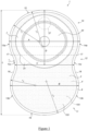
- an ostomy pouch 1 comprises a rear wall 2, a front wall 3, a separation wall 4, a rear comfort layer 5, a front comfort layer 6 and an ostomy wafer 7.
- a separation wall 4 may be omitted if desired.
- the ostomy pouch 1 is a one-piece pouch wherein the ostomy wafer 7 is permanently attached to the ostomy pouch 1 (in the sense that it cannot be easily removed and re-attached without damaging the pouch).
- other embodiments may be a two-piece pouch comprising a pouch component and body fitment component that together form the ostomy pouch.
- the pouch comprises the rear wall 2, the front wall 3, the separation wall 4, the rear comfort layer 5 and the front comfort layer 6, and the body fitment component comprises the ostomy wafer 7.
- the rear wall 2 and the front wall 3 define a cavity for containing a stomal output.
- the rear wall 2 and the front wall 3 are both formed of flexible sheet material in the form of a plastics film and are joined together to define the cavity.
- An exemplary film is polyethylene (PE).
- the film typically has a thickness of 75 to 100 ⁇ m but in some embodiments may have a thickness of 50 to 150 ⁇ m.
- the ostomy pouch 1 has an upper section 10, a lower section 11 and a waisted section 12 that is located between the upper section 10 and the lower section 11.
- the upper section 10 has a maximum width, A
- the lower section 11 has a maximum width, B
- the waisted section, 12 has a minimum width, C.
- the maximum width, A, of the upper section 10 is greater than the maximum width, B, of the lower section 11, which in turn is greater than the minimum width, C, of the waisted section 12.
- the ostomy pouch 1 has a left-hand 13 and right-hand 14 edge when viewed from the rear.
- the waisted section 12 has a left-hand edge 13c and a right-hand edge 14c that are both smoothly rounded and merge into the respective left-hand edges 13a, 13b and right-hand edges 14a, 14b of the upper section 10 and the lower section 11.
- the shape and dimensions of the ostomy pouch 1 are not particularly limited so long as it remains discreet and comfortable to wear in use.
- the ostomy pouch has a length, L, of 208 mm, maximum width of the upper section A and lower section of 142 mm and 137 mm respectively, and a minimum width of the waisted section C of 119 mm.
- the minimum width, C is located at a distance, D, from a top edge of the ostomy pouch 1, in this embodiment D is 119 mm.
- the left-hand edge 13c and the right-hand edge 14c of the waisted section 12 have concave curvature with a radius of curvature, r1, of 40 mm.
- both the upper 10 and lower 11 sections are rounded and comprise continuously curved edges 15, 16 respectively.
- the curved edges 15, 16 extend from the upper and lower ends of left-hand edge 13c of the waisted section 12 to the corresponding upper and lower ends of the right-hand edge 14c of the waisted section 12.
- the edges 15, 16 are convexly curved with a radius of curvature of r2 and r3 respectively.
- the r2 and r3 are constant along their respective edges 15, 16, however in alternative embodiments they may be variable.
- r2 is in the range 55 mm and 75 mm, preferably 60 to 73 mm
- r3 is in the range 45 mm to 70 mm, preferably 50 mm to 67 mm.
- the upper section edge 15 incorporates the left-hand edge 13a and the right-hand edge 14a of the upper section 10 while the lower section edge 16 incorporates the corresponding left-hand 13b and right-hand edge 14b of the lower section.
- a junction between the upper section 10 and the waisted section 12 may be demarcated by a single point of inflection 17 between the edges 13a, 14a of the upper section 10 and the edges 13c, 14c of the waisted section 12.
- a junction between the lower section 11 and the waisted section 12 may be demarcated by a single point of inflection 18 between the edges 13b, 14b of the lower section 11 and the edges 13c, 14c of the waisted section 12.
- the rear wall 2 and the front wall 3 are symmetrical about a vertical midline of the ostomy pouch 1.
- the rear wall 2 and front wall 3 are joined around their peripheral edges by use of welding. Welding is a preferred method of joining the rear wall 2 and the front wall 3 as it allows all the layers of the pouch 1 to be joined simultaneously, as described later.
- the rear wall 2 and the front wall 3 are joined together by a single continuous edge seal 8 that extends around a full perimeter of the rear wall 2 and the front wall 3 to create a fluid-tight seal.
- the single continuous edge seal 8 has a constant width of 4 mm around the perimeter of the ostomy pouch 1. In other embodiments, the width may be of different width, for example in the range 3 mm to 5 mm and may also vary around the perimeter.
- the rear wall 2 is provided with a stomal inlet 20 for receiving the stomal output into the cavity.
- the stomal inlet 20 is an aperture that is cut out of the rear wall 2 in the upper section 10 of the ostomy pouch 1, in which the wafer 7 is provided, the wafer having a hole through which a stoma normally extends.
- the rear comfort layer 5 and front comfort layer 6 are substantially the same shape as the rear 2 and front 3 walls.
- the rear 5 and front 6 comfort layers form the outside of the ostomy pouch 1 and cover the rear 2 and front 3 walls respectively.
- the rear comfort layer 5 also comprises a wafer aperture that is in register with the stomal inlet 20 of the rear wall 2, in which the wafer 7 is arranged.
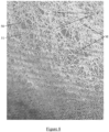
- the rear comfort layer 5 and the front comfort layer 6 are formed of a flexible sheet material comprised of a woven fabric layer 50 with a web of hot-melt adhesive 51 coated on one surface - its inside surface in use (see Figure 8 ).
- the fabric layer 50 forms the outside surface of the rear 5 and front 6 comfort layers respectively, with the web of hot-melt adhesive 51 disposed on the corresponding inside surfaces, facing the rear 2 and front 3 walls.
- Other embodiments may comprise additional fabric layers and/or adhesive layers as required.
- the woven fabric layer comprises polyester but in other embodiments any one or more of nylon, viscose, polyethylene and polypropylene could be used in addition or as an alternative.
- the woven fabric layer has an area density of 58 g/m 2 , a tensile strength of 280 to 300 N, and a tear strength of 18 N.
- Other embodiments may have different compositions, for example an area density of 50 to 70 g/m 2 , a tensile strength of 200 to 400 N, and a tear strength of 10 to 30 N.
- Some embodiments may also have a colour fastness to any one or more of rubbing, perspiration or washing (40°) of 4 to 5, and an abrasion of >50,000.
- Certain embodiments also comprise a woven polyester with a water repellent finish.
- the water repellent finish may be fluorocarbon based and may be dyed heat set or boil off heat set.
- a suitable woven polyester layer is available from Newton Textiles Limited of Northamptonshire, UK, under the 75DCWR Designation, such as 75DCWRWHITE (for a white variant).
- the hot-melt adhesive comprises ethylene-vinyl acetate (EVA).
- the hot-melt adhesive is a polyolefin.
- the hot-melt adhesive is polyurethane.
- the hot-melt adhesive is polyvinylidene chloride (PVDC).
- the hot-melt adhesive is silicon rubber.
- the hot-melt adhesive is a fluoropolymer.
- the hot-melt adhesive is polycarbonate.
- the hot-melt adhesive is styrene block co-polymer.
- the hot-melt adhesive is polyester.
- the hot-melt adhesive is polyamide.
- the hot-melt adhesive is polycaprolactone.
- the web of hot-melt adhesive has an area density of 25 g/m 2 .
- a suitable EVA hot-melt adhesive is available from Protechnic SA of Cernay, France under the designation 3Z8.
- the hot-melt adhesive is coated onto the fabric layer over an entire area of the rear 5 and the front 6 comfort layers. In other embodiments, the hot-melt adhesive may be coated to part of area of the rear 5 and front 6 comfort layers, or specific regions thereof.
- the web is formed, as shown in figure 8 , it includes a mass M of hot-melt adhesive with numerous voids V therein, where there is an absence (or substantial absence, possibly including a trace) of hot-melt adhesive, thus it takes the general form of a lattice, mesh or grid.
- the voids are irregularly shaped and spaced and a relatively smaller area is covered by the mass than that which is free of adhesive in the voids.
- the voids could be regularly shaped and/or regularly spaced.
- the use of the hot melt adhesive allows both comfort layers 5, 6 and both walls 2, 3 to be joined together simultaneously in the same welding process if desired, in the same manner as a non-woven material would be attached, improving the bond, without the need for specialist intervening layers or the application of adhesive during the construction process.
- the peripheral weld defined by the edge seal 8 also joins the rear comfort layer 5 to the rear wall 2 and the front comfort layer 6 to the front wall 3.
- various welds may be used as required or desired.
- the weld may only correspond to a portion of the weld joining the rear 2 and front 3 walls.
- the weld attaching the rear comfort layer 5 to the rear wall 2 may be different from the weld attaching the front comfort layer 6 to the front wall 3.
- the hot-melt adhesive 51 protects the fabric layers 50 from undesirable fraying.
- the front comfort layer 6 comprises an upper part 6a and a lower part 6b, which when taken together are the same shape as the front wall 3.
- the upper 6a extends from the top of the pouch 1 to the point of inflection 17 between the upper section 10 and waisted section 12.
- the lower part 6b extends from the bottom of the pouch 1, beneath the upper part 6a to a point slightly above the point of inflection 17.
- the upper 6a part partially overlaps the lower part 6b in an overlap region 115.
- the upper part 6a and the lower part 6b are separable from each other in the overlap region 115 to form a window opening for viewing the cavity.
- the overlap region 115 extends horizontally when the ostomy pouch 1 is in use.
- the overlap region 115 may not coincide with the point of inflection 17 and may span the pouch 1 at any suitable location along its length.
- the two parts 6a, 6b, of the front comfort layer 6 would not bond to one another at all, regardless of the choice of material for the walls 2,3, because the material of the wall is not involved in the bond in that region. This therefore is a key region for the presence of the hot-melt adhesive.
- the front layer may be comprised of multiple parts.
- the external shape and dimensions of the multiple parts when taken together may be the same as that of the front wall 3.
- the ostomy wafer 7 is in register with the stomal inlet 20 of the rear wall 2 and extends through the wafer aperture of the rear comfort layer 5.
- the ostomy wafer 7 comprises an adhesive and a release liner 31.
- the ostomy wafer 7 is mounted to the rear wall 2 by welding. In other embodiments the wafer 7 may be mounted by any suitable alternative means (e.g. adhesive).
- the ostomy pouch 1 may also be provided with a gas vent for venting of stomal gases from the cavity.
- the ostomy pouch 1 comprises a gas vent filter 24 which is also an odour filter. Suitable filters could be a charcoal or activated carbon filter, for reducing the release of unwanted odours from the cavity.
- the gas vent filter 24 forms a part of the gas vent, which comprises a gas vent aperture 27 located in the front wall 3.
- the gas vent filter 24 is covered by a filter cap and the gas vent filter 24 and filter cap are located on the front wall 3 over the gas vent aperture 27.
- the gas vent aperture 27 permits the passage of gas from the cavity towards an exterior of the ostomy pouch through the gas vent filter 24 and filter cap.
- the gas vent is located, in use, in the upper quarter of the ostomy pouch 1.
- the centre of the gas vent aperture 27 is disposed, in use, above the centre of the stomal inlet 20.
- the gas vent may be located elsewhere in the upper section 10 of the ostomy pouch 1.
- the separation wall 4 is located between the rear wall 2 and the front wall 3.
- the separation wall 4 comprises a separation filter 100 for filtering stomal gases and/or stomal liquids from stomal solids contained in the stomal output.
- the separation filter 100 thus prevents stomal solids from contacting the gas vent and clogging or otherwise impairing the functionality of the gas vent filter 24.
- the separation wall 4 has the same external shape and dimensions as the rear wall 2 and the front wall 3 and divides the cavity of the ostomy pouch 1 into a first and a second chamber 101, 102.
- the first chamber 101 extends between the separation wall 4 and the rear wall 2, and the second chamber 102 extends between the separation wall 4 and the front wall 3.
- the first and second chambers 101, 102 have substantially the same volume. In other embodiments, they may have different volumes and/or the second chamber 102 may have a larger volume than the first chamber 101.
- the separation wall 4 is joined to the rear wall 2 and front wall 3 at their peripheral edges by use of welding to create a fluid-tight seal therebetween.
- the separation wall 4 is joined to the rear 2 and front 3 walls about the whole of the edge of the upper section 10, and is additionally joined to the front wall 3 by a horizontal weld at the interface between the upper 10 and waisted 12 sections. Therefore, the joining of the separation wall 4 with the rear and front walls 2, 3 according to some embodiments of the invention may be such that the first and second chambers 101, 102 are sealed from one another other than via the separation filter 100.
- the separation wall 4 comprises a flexible sheet material, which may be formed of polyurethane, polyethylene (PE), polyvinylidene chloride (PVDC) and/or ethylene-vinyl acetate (EVA).
- the flexible sheet material of the separation wall 4 has a thickness of 50 to 150 micrometres, preferably 75 to 100 micrometres.
- the separation wall 4 comprises a hydrophobic and oleophobic coating applied to the flexible sheet material.
- the flexible sheet material may be hydrophobic and/or oleophobic.
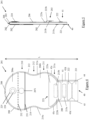
- a further embodiment of an ostomy pouch 201 is similar to that shown in Figures 1 to 3 , with like features having similar reference numerals.
- the main difference is that the lower section 211 of the further embodiment is shaped to accommodate/form a foldable drain.
- this embodiment of the ostomy pouch 201 is an open pouch that does not comprise a sealed perimeter.
- the rear wall 202 features a large opening 202i in register with the stomal inlet 207i of the wafer 207 (which is connected to the rear wall 202 in the region between the periphery of the opening 202i and the periphery of the wafer, such that stomal output enters the cavity via the stomal inlet of the wafer and the opening 202i in the rear wall.
- the rear comfort layer 205 also features an opening 205i slightly larger than the opening 202i in the rear wall 202 and in register with it, so as to be sandwiched between the outermost edge of the wafer and the rear wall 202.
- the stomal inlet 207i is adjustable to fit the stoma of the ostomate.
- the front comfort layer 206 of this embodiment is formed of two parts: an upper part 206a; and a lower part 206b.
- the upper part 206a overlaps the lower part 206b across the majority of the width of the pouch 201 at a point on its height in register with the stomal inlet 207i.
- the overlap being defined by the lower edge 231 of the upper part 206a that overlaps the upper edge 232 of the lower part 206b.
- an optional gas filter 224 positioned in the front wall 203 at a height above the stomal inlet 207i to allow gas to exit the pouch 201.
- the filter 224 is covered by an optional filter cover patch 225 (not shown in Figure 5 ) on the outside surface of the front wall 203.
- the filter 224 and filter cover patch 225 are covered by the upper part 206a of the front comfort layer 206.
- the drain extends from the lower edge of the ostomy pouch 201 such that the pouch 201 has a length, L, of 290 mm when the drain is in an unfolded configuration.
- the length may be a different size, for example in the range 250 mm to 300 mm.
- the lower section 211 comprises a drain aperture 40.
- the drain aperture 40 is an unsealed portion of the perimeter of the ostomy pouch 201 where the rear 202 and front 203 walls are not sealed.
- the lower section 211 comprises a rounded portion 211a and a substantially rectangular drain portion 41 that accommodates the drain aperture 40, with the rounded portion 211a being adjacent the waisted section 212 and the drain portion 41 being distal the waisted section 212.
- the drain portion 41 is foldable along its length between an unfolded and a folded configuration as described later.
- the lower section 211 comprises a continuous left edge 42 that extends from the left edge 213c of the waisted section 212 to a left vertex 44 of the drain aperture 40 around the curved left edge 42c of the generally rounded portion 211a and along a left edge 42d of the drain portion 41.
- a continuous right-hand edge 43 extends from the right edge 214c of the waisted section 212 to a right vertex 45 of the drain aperture 40 around a continuously curved right edge 43c of the generally rounded portion 211a and along a right edge 43d of the drain portion 41.
- the curved left 42c and right edges 43c of the generally rounded portion 211a have convex curvature.
- the radius of curvature, r3 is similar to the radius of curvature r2 as described for the ostomy pouch shown in Figures 1 to 3 .
- the left 42d and right 43d edges of the drain portion 41 are parallel to one another along the majority of their length.
- a single continuous edge seal 208 extends around the perimeter of the pouch 201 from the left vertex 44 of the drain aperture 40 to the right vertex 45 of the drain aperture 40, leaving the distal end of the drain aperture 40 open.
- the drain portion 41 defines an elongate drain passage that extends from the cavity of the ostomy pouch 201 to the drain aperture 40 located at a lower end of the drain portion 41.
- the drain portion 41 is integral with the lower section 211 and as such, the rear wall 202 and the front wall 203 may each be a single piece of material that includes the upper section 210, the waisted section 212 and lower section 211 (including the drain portion 41).
- the rear comfort layer 205 and front comfort layer 206 do not cover the drain portion 41 of the rear wall 202 and the front wall 203.
- communication between the cavity and the elongate drain passage is via a drain inlet 200 defined as the point of transition between the cavity and the drain portion 41.
- the drain inlet 200 allows passage of stomal output from the cavity into the drain portion 41 when the drain portion 41 is unfolded.
- movement of the drain portion 41 between its unfolded or folded configuration opens or closes the drain aperture 40. This either permits or prevents outflow of the stomal output stored in the ostomy pouch 1 cavity.
- the drain portion 41 can be repeatedly folded in the same sense along its length into a plurality of segments having approximately equal segment lengths and separated by folds.
- the drain portion 41 may therefore be successively folded one or more times such that the segments overlie each other.
- Each fold is formed across the width of the drain portion 41 and acts to inhibit and preferably prevent passage of stomal output out of the drain aperture 40.
- first 221 and second 222 pursing strips are provided on the drain portion 41.
- the pursing strips 221, 222 provide both localised rigidity to the drain portion 41 and also define the locations and orientations of the segments and folds of the drain portion 41.
- the pursing strips 221, 222 comprise strips of flexible material attached drain portion 41, wherein the strips 221, 222 have a higher rigidity than the material of the drain portion 41.
- the pursing strips 221, 222 also have some resilience such that once attached to the drain portion 41, the pursing strips 221, 222 can each be squeezed laterally to arch the pursing strip and thereby open the elongate drain passage. In other embodiments, two or more pursing strips may be used.
- the pursing strips 221, 222 are formed from polystyrene, but other embodiments may comprise any suitable material.
- the first pursing strip 221 is attached to the rear wall 202 of the drain portion 41 adjacent the drain aperture 40.
- the second pursing strip 222 is attached to the front wall 203 of the drain portion 41 above the second strip 222.
- a longitudinal gap is provided between an upper edge of the first pursing strip 221 and a lower edge of the second pursing strip 222. The longitudinal gap therefore defines the location of a first fold of the drain portion 41.
- Each pursing strips 221, 222 spans the width of the drain portion 41 and extends the same distance along a length of the drain portion 41.
- a rear fastening element 215a is arranged on the rear wall 202 and a front fastening element 215b is arranged on a flap 223 that is mounted to the front comfort layer 206.
- the flap 223 is mounted to the lower part 206b of the comfort layer 206.
- the rear fastening element 215a and the front fastening element 215b comprise corresponding hook-and-loop type fastener elements.
- the rear fastening element 215a is located on the drain portion 41 above the second pursing strip 222.
- a longitudinal gap is provided between an upper edge of the second pursing strip 222 and a lower edge of the rear fastening element 215a. The longitudinal gap therefore defines the location of a second fold of the drain portion 41.
- the flap 223 comprises a first flange 223a and a second flange 223b formed of one integral piece.
- the first flange 223a spans substantially all of the width of the lower rounded section 211a, but does not extend over the edge seal 208, at a point one third up the length of the rounded section 211a from the drain inlet 200.
- the first flange 223a is attached to the comfort material 206 by a single weld that spans substantially its entire width. This weld is made possible by the web of hot-melt adhesive 51 which coats the inside surface of the woven material 50 that the comfort material 206 is made from, which, when heated penetrates the woven material to bond with the material of the flap 223.
- the second flange 223b extends from the lower edge of the first flange 223a and is connected to the pouch 1 only by the first flange 223a.
- the second flange 223b is contoured so as to conform to the shape of the rounded portion 211a but is thinner, tracing the inside edge of the peripheral weld 208. As such, the second flange 223b extends downwards from the first flange 223a within the perimeter defined by the edge seal 208 of the pouch 201.
- the flap 223 has an outside surface, facing away from the ostomate in use and an opposite inside surface.
- the front fastening element 215b is located on the inside surface of the second flange 223b at a position above the rear fastening element 215a.
- a longitudinal gap is provided between an upper edge of the rear fastening element 215a and a lower edge of the front fastening element 215b and defines the location of a third fold of the drain portion 41.
- the flap 223 is formed from a flexible sheet material that is more rigid than the flexible sheet material of the rear wall 202, front wall 203 and comfort layers 205, 206.
- the flap 223 is formed from a plastic foam which provides a desirable rigidity.
- the flap 223 is formed of the same hot-melt coated woven comfort material as the comfort layer 206. Whilst this material is not as rigid as a plastic foam material, it is desirable aesthetically, as it matches with the remainder of the comfort layer, making the fact that the pouch is drainable less obvious.
- Folding of the drain portion 41 may be carried out as follows. First, the distal end of the drain portion 41 is folded upwards and away from the rear of the ostomy pouch 201 about the first fold line to locate the first pursing strip 221 over the second pursing strip 222. Secondly, the drain portion 41 and the pursing strips 221, 222 are folded again, in the same sense, about the second fold line and then the third fold line such that the folded and stacked first pursing strip 221, second pursing strip 222 and first fastening element 215a are located beneath the second flange 223b of the flap 223 with the rear fastening element 215a being exposed and adjacent the front fastening element 215b. Finally, the second flange 223b of the flap 223 is pressed onto the folded drain portion to secure together the rear fastening element 215a and the front fastening element 215b.
- the drain portion 41 can then be unfolded by reversing the above procedure.
- the rear comfort layer 205 and the front comfort layer 206 are formed of a flexible sheet material comprised of a woven fabric layer 50 with a web of hot-melt adhesive 51 coated on one surface - its inside surface in use (see Figure 8 ).
- the fabric layer 50 is forms the outside surface of the rear 205 and front 206 comfort layers respectively, with the web of hot-melt adhesive 51 disposed on the corresponding inside surfaces, facing the rear 202 and front 203 walls.
- Other embodiments may comprise additional fabric layers and/or adhesive layers as required.
- the woven fabric layer comprises polyester but in other embodiments any one or more of nylon, viscose, polyethylene and polypropylene could be used in addition or as an alternative.
- the woven fabric layer has an area density of 58 g/m 2 , a tensile strength of 280 to 300 N, and a tear strength of 18 N.
- Other embodiments may have different compositions, for example an area density of 50 to 70 g/m 2 , a tensile strength of 200 to 400 N, and a tear strength of 10 to 30 N.
- Some embodiments may also have a colour fastness to any one or more of rubbing, perspiration or washing (40°) of 4 to 5, and an abrasion of >50,000.
- Certain embodiments also comprise a woven polyester with a water repellent finish.
- the water repellent finish may be fluorocarbon based and may be dyed heat set or boil off heat set.
- a suitable woven polyester layer is available from Newton Textiles Limited of Northamptonshire, UK, under the 75DCWR Designation, such as 75DCWRWHITE (for a white variant).
- the hot-melt adhesive comprises ethylene-vinyl acetate (EVA).
- the hot-melt adhesive is a polyolefin.
- the hot-melt adhesive is polyurethane.
- the hot-melt adhesive is polyvinylidene chloride (PVDC).
- the hot-melt adhesive is silicon rubber.
- the hot-melt adhesive is a fluoropolymer.
- the hot-melt adhesive is polycarbonate.
- the hot-melt adhesive is styrene block co-polymer.
- the hot-melt adhesive is polyester.
- the hot-melt adhesive is polyamide.
- the hot-melt adhesive is polycaprolactone.
- the web of hot-melt adhesive has an area density of 25 g/m 2 .
- a suitable EVA hot-melt adhesive is available from Protechnic SA of Cernay, France, under the designation 3Z8 and described by Protechnic SA as a web, but other hot-melts, such a co-polyester hotmelt web were evaluated successfully.
- the hot-melt adhesive is once again coated onto the fabric layer over an entire area of the rear 205 and the front 206 comfort layers.
- the hot-melt adhesive may be coated to part of area of the rear 205 and front 206 comfort layers, or specific regions thereof.
- the web includes a mass M of hot-melt adhesive with numerous voids V therein, where there is an absence (or substantial absence, possibly including a trace) of hot-melt adhesive, thus it takes the general form of a lattice, mesh or grid.
- the voids are irregularly shaped and spaced and a relatively smaller area is covered by the mass than that which is free of adhesive in the voids.
- the voids could be regularly shaped and/or regularly spaced.
- the use of the hot melt adhesive allows both comfort layers 205, 206 and both walls 202, 203 to be joined together simultaneously in the same welding process if desired, in the same manner as a non-woven material would be attached, without the need for specialist intervening layers or the application of adhesive during the construction process and with adhesion even in regions where woven layers are joined to each other (i.e. the overlap) or to other materials that would not normally weld to a woven layer (such as the flap 223).
- the peripheral weld defined by the edge seal 208 also joins the rear comfort layer 205 to the rear wall 202 and the front comfort layer 206 to the front wall 203. In other embodiments, various welds may be used as required or desired.
- the weld may only correspond to a portion of the weld joining the rear 202 and front 203 walls.
- the weld attaching the rear comfort layer 205 to the rear wall 202 may be different from the weld attaching the front comfort layer 206 to the front wall 203.
- the hot-melt adhesive 51 protects the fabric layers 50 from undesirable fraying.
- an ostomy pouch 1001 is identical to that of figures 1-3 (hence corresponding numbering), with the exception that instead of comprising a front comfort layer 6 made up of an upper comfort layer 6a and a lower comfort layer 6b both coated in the hot-melt adhesive, in this embodiment the upper comfort layer 6a is identical and coated with hot-melt adhesive, but the lower comfort layer 6bi is uncoated.
- an apparatus 300 comprises four rollers 301, 302, 303 and 304, a stamp welding machine 305, and a cutting machine 306.
- the rollers 301, 302, 303, 304 are used to advance a first 311, a second 312, a third 313 and a fourth 314 flexible sheet material respectively in the direction of the arrow, D.
- additional rollers used to advance the webs are not shown.
- the apparatus 300 is configured to construct an ostomy pouch 310 similar to the ostomy pouches 1, 201 of Figures 1 to 6 and 9 comprising a rear comfort layer 5, 205, rear wall 2, 202, front wall 3, 203 and front comfort layer 6, 206.
- the process is shown simplified, without features such as the separation layer 4 or aspects of the drain portion 41 described in the embodiments above and without any description of the assembly of the wafer, filter and so forth, which can be provided in manner which will be well known to those skilled in the art.
- the first 311 and second 312 sheets of material are plastics film used for the rear and front walls of the pouch 310 respectively. As such, the materials used for these sheets are the same and correspond to that described in relation to the ostomy pouches 1, 201 described above.
- the third 313 and fourth 314 sheets of material are used for the rear and front comfort layers of the pouch 310 respectively.
- the material used for the comfort layers comprise a woven fabric layer 50 with a web of hot-melt adhesive 51 applied thereto.
- the third 313 and fourth 314 sheets of material comprise a woven fabric layers 313a, 314a with adhesive webs 313b, 314b coated thereon.
- the webs of hot-melt adhesive (denoted by dashed lines) face towards one another, with the first and second layers of sheet material arranged between them.
- the third 313 and fourth 314 sheets of material have been previously formed in a separate facility, days earlier, by a coating process, such as a roll-coating process, in which a thin sheet of EVA film is advanced from a roll and laminated under heat and pressure onto sheet of woven material 50 similarly advanced from a roll, then cooled and rolled onto a new roll, on which it is delivered.
- a coating process such as a roll-coating process, in which a thin sheet of EVA film is advanced from a roll and laminated under heat and pressure onto sheet of woven material 50 similarly advanced from a roll, then cooled and rolled onto a new roll, on which it is delivered.
- the thinness of the EVA film combined with the heating during lamination causes the formation of the voids V in the mass M of the EVA web 51 that is formed.
- the stamp welding machine 305 is arranged to weld together the layers of material using a hot stamp.
- the shape of the weld corresponds to the perimeter edge seal 8 as described in the ostomy pouches 1, 201 of Figures 1 to 3 and 4-6 .
- the cutting machine 306 is arranged to cut sections of the advancing sheet of material in the shape defined by the perimeter of the ostomy pouch.
- first, the first 311 and second 312 sheets of material are brought together by rollers (not shown) such that they are in contact and advance at the same rate as one another.
- the third 313 and fourth 314 sheets of material are brought together on opposite sides of the first 311 and second 312 sheets by rollers (not shown).
- the third sheet 313 is brought adjacent to the first sheet 311 such that the web of adhesive 313b faces the first sheet 311.
- the fourth sheet 314 is brought adjacent the second sheet 213 such that the web of hot-melt adhesive 314b faces the second sheet 312.
- all four sheets are in contact and advance at the same rate.
- the sheets thus are stacked in the following order: third 313; first 311; second 312; and, fourth 314.
- the advancing sheet of material then enters the stamp welding machine 305.
- the stamp welding machine 305 applies the heated stamp to the advancing sheet creating a sealed weld line 315 that corresponds to the perimeter of the ostomy pouch 310.
- the heated stamp is applied to the comfort layer which will be at the rear in use, since direct application of heat can cause the hot-melt adhesive to leak so far through the fabric layer as to become visible, it is preferred that this visibility is on the side not visible in use.
- the webs of hot-melt adhesive 313b and 314b facilitate the fabric layers 313a and 314a welding to the first 311 and second 312 layers.
- This process generates a series of sealed ostomy pouches 310 in the advancing sheets.
- the stamping machine only welds around the perimeter of the pouches, leaving a cavity within the pouch 310.
- the advancing sheets then enter the cutting machine 306.
- the cutting machine cuts around the perimeter of the sealed weld line 315 created by the stamping machine 305. This frees each ostomy pouch 310 from the advancing sheets where they can be collected or further prepared. Welding and cutting could of course take place simultaneously.
- a fifth sheet of comfort layer material is used (not shown) and is applied on the same side of the pouch as the third 313 sheet.
- the third 313 and fifth sheets can be welded to the pouch simultaneously with the other layers, forming the pouch with an overlapping region 115 in a single stamp welding process.
Landscapes
- Health & Medical Sciences (AREA)
- Epidemiology (AREA)
- Nursing (AREA)
- Orthopedic Medicine & Surgery (AREA)
- Engineering & Computer Science (AREA)
- Biomedical Technology (AREA)
- Heart & Thoracic Surgery (AREA)
- Vascular Medicine (AREA)
- Life Sciences & Earth Sciences (AREA)
- Animal Behavior & Ethology (AREA)
- General Health & Medical Sciences (AREA)
- Public Health (AREA)
- Veterinary Medicine (AREA)
- Orthopedics, Nursing, And Contraception (AREA)
- Materials For Medical Uses (AREA)
- Bag Frames (AREA)
- Laminated Bodies (AREA)
Claims (15)
- Ostomiebeutel (1, 201, 1001) umfassend eine Schicht aus gewebtem Komfortmaterial (6, 206), wobei die Schicht aus gewebtem Komfortmaterial (6, 206) eine äußere Oberfläche und eine gegenüberliegende innere Oberfläche aufweist, wobei die äußere Oberfläche der Schicht aus gewebtem Komfortmaterial (6, 206) mindestens einen Teil der äußeren Oberfläche des Beutels bildet, und mindestens ein Teil der Schicht aus gewebtem Komfortmaterial (6, 206) mit einem Heißschmelzklebstoff (51) beschichtet ist; wobei eine Schicht aus gewebtem Komfortmaterial (6, 206), die die Vorderseite des Beutels bedeckt, einen oberen Teil (6a) und einen unteren Teil (6b) umfasst, die sich in einem Überlappungsbereich (115) überlappen; und der Heißschmelzklebstoff (51) auf einem oder beiden Teilen in dem Überlappungsbereich (115) bereitgestellt ist.
- Ostomiebeutel (1, 201, 1001) nach Anspruch 1, wobei der Ostomiebeutel (1, 201, 1001) umfasst: eine vorderseitige Oberfläche, die bei Verwendung vom Ostomiepatienten abgewandt ist; eine rückseitige Oberfläche, die bei Verwendung dem Ostomiepatienten zugewandt ist; und eine Schicht aus gewebtem Komfortmaterial (6, 206), die auf ihrer inneren Oberfläche mit einem Heißschmelzklebstoff (51) beschichtet ist und sowohl die vorderseitige als auch die rückseitige Oberfläche des Beutels bildet.
- Ostomiebeutel (1, 201, 1001) nach Anspruch 1 oder Anspruch 2, wobei der Heißschmelzklebstoff ein Netz ist, das eine Masse (M) und eine Mehrzahl von Hohlräumen (V) in der Masse (M) umfasst, wobei bevorzugt die Hohlräume (V) mindestens 50% des Netzes ausmachen.
- Ostomiebeutel (1, 201, 1001) nach einem der Ansprüche 1 bis 3, wobei der Heißschmelzklebstoff (51) auf die gesamte innere Oberfläche des gewebten Komfortmaterials (6, 206) aufgebracht ist.
- Ostomiebeutel (1, 201, 1001) nach einem der Ansprüche 1 bis 3, wobei die innere Oberfläche der oder jeder Schicht aus gewebtem Komfortmaterial (6, 206) in einen oder mehrere Bereiche geteilt ist, wobei Heißschmelzklebstoff (51) auf einen oder mehrere der Bereiche aufgebracht ist.
- Ostomiebeutel (1, 201, 1001) nach einem der vorhergehenden Ansprüche, wobei der Ostomiebeutel eine faltbare Drainage (41) umfasst, wobei in einer gefalteten Konfiguration die Drainage (41) innerhalb des äußeren Umfangs des Ostomiebeutels (1, 201, 1001) bleibt; wobei die Drainage (41) in der gefalteten Konfiguration durch ein Verschlussmittel gehalten wird, das an der oder einer Schicht aus Komfortmaterial (6, 206) angebracht ist; und wobei das Verschlussmittel eine Klappe (223) umfasst, die entlang der Oberkante der Klappe (223) mit dem gewebten Komfortmaterial (6, 206) verschweißt ist.
- Ostomiebeutel (1, 201, 1001) nach einem der vorhergehenden Ansprüche, wobei der Heißschmelzklebstoff (51) am Umfang der Schicht aus gewebtem Komfortmaterial (6, 206) aufgebracht ist und eine Flächendichte von 20-30 g/m2 aufweist.
- Ostomiebeutel (1, 201, 1001) nach einem der vorhergehenden Ansprüche 1, wobei das gewebte Komfortmaterial (6, 206) Polyester umfasst.
- Ostomiebeutel (1, 201, 1001) nach einem der vorhergehenden Ansprüche, wobei der Heißschmelzklebstoff Ethylen-Vinylacetat (EVA) umfasst.
- Verfahren zum Bilden eines Ostomiebeutels (1, 201, 1001) gemäß einem der Ansprüche 1 bis 9, wobei das Verfahren umfasst: Beschichten mindestens eines Teils einer Seite einer Schicht aus gewebtem Komfortmaterial (6, 206) mit einem Heißschmelzklebstoff (51), um eine innere Oberfläche bereitzustellen, die die Beschichtung umfasst; Bereitstellen einer Rückwand (2, 202) und einer Vorderwand (3, 203), die eine Kavität zur Aufnahme des Stomaausgangs definieren; Anordnen der inneren Oberfläche der Schicht aus gewebtem Komfortmaterial (6, 206) angrenzend an die Rückwand (2, 202) und/oder die Vorderwand (3, 203); und Verbinden der inneren Oberfläche der Schicht aus gewebtem Komfortmaterial (6, 206) mit einer oder mehreren der Rückwand (2, 202) und/oder Vorderwand (3, 203) des Ostomiebeutels (1, 201, 1001).
- Verfahren nach Anspruch 10, wobei das Verfahren das Verbinden einer vorderen Schicht aus gewebtem Komfortmaterial (6, 206), die auf ihrer inneren Oberfläche einen Heißschmelzklebstoff (51) aufweist, mit der Vorderwand (3, 203) und einer hinteren Schicht aus gewebtem Komfortmaterial (6, 206), die auf ihrer inneren Oberfläche einen Heißschmelzklebstoff (51) aufweist, mit der Rückwand (2, 202) des Stomabeutels (1, 201, 1001) umfasst und wobei das Verbinden des Beutels durch Schweißen erfolgt.
- Verfahren nach Anspruch 10 oder 11, wobei die Vorderwand (3, 203) eine transparente Schicht aus flexiblem Material umfasst und das Verfahren das Verbinden der inneren Oberfläche der Schicht aus gewebtem Komfortmaterial (6, 206) mit der Vorderwand (3, 203) enthält.
- Verfahren nach einem der Ansprüche 10 bis 12, wobei der Schritt des Aufbringens des Heißschmelzklebstoffs (51) auf eine Seite einer Schicht aus gewebtem Komfortmaterial (6, 206) mindestens 1 Stunde vor dem Verbinden der inneren Oberfläche der Schicht aus Komfortmaterial (6, 206) mit der Wand durchgeführt wird.
- Ostomiebeutel (1, 201, 1001) nach Anspruch 2 oder einem davon abhängigen Anspruch, wobei ein Netz aus Heißschmelzklebstoff (51) mindestens den oberen Teil der hinteren Oberfläche, die bei Verwendung dem Ostomiepatienten zugewandt ist, beschichtet; und ein Netz aus Heißschmelzklebstoff (51) mindestens den oberen Teil (6a) der Schicht aus gewebtem Komfortmaterial (6, 206), die die Vorderseite des Beutels bedeckt, beschichtet.
- Ostomiebeutel (1, 201, 1001) nach einem der Ansprüche 1 bis 9 oder 14, umfassend eine Kavität zur Aufbewahrung von Stomaausgang; wobei die Kavität durch eine Rückwand (2, 202) und eine Vorderwand (3, 203) definiert ist, die an ihrem Umfang miteinander verbunden sind und aus flexiblem Schichtmaterial gebildet sind; wobei die inneren Oberflächen der Rück- (2, 202) und der Vorderwand (3, 203) das Innere der Kavität bilden und die äußeren Oberflächen der Rück- (3, 203) und der Vorderwand (2, 202) das Äußere der Kavität bilden; wobei die Schicht aus gewebtem Komfortmaterial (6, 206) die äußere Oberfläche der Vorderwand (3, 203) bedeckt; und wobei mindestens ein Teil des Heißschmelzklebstoffs (51) sich auf der inneren Oberfläche des Komfortmaterials (6, 206) befindet und an die äußere Oberfläche der Vorderwand (3, 203) angrenzt, ihr zugewandt ist und nicht mit ihr verbunden ist.
Priority Applications (1)
| Application Number | Priority Date | Filing Date | Title |
|---|---|---|---|
| EP24197666.1A EP4445882A3 (de) | 2020-06-02 | 2021-06-01 | Ostomiebeutel |
Applications Claiming Priority (2)
| Application Number | Priority Date | Filing Date | Title |
|---|---|---|---|
| GBGB2008262.4A GB202008262D0 (en) | 2020-06-02 | 2020-06-02 | Ostomy pouch |
| PCT/GB2021/051340 WO2021245397A1 (en) | 2020-06-02 | 2021-06-01 | Ostomy pouch |
Related Child Applications (1)
| Application Number | Title | Priority Date | Filing Date |
|---|---|---|---|
| EP24197666.1A Division EP4445882A3 (de) | 2020-06-02 | 2021-06-01 | Ostomiebeutel |
Publications (3)
| Publication Number | Publication Date |
|---|---|
| EP4157166A1 EP4157166A1 (de) | 2023-04-05 |
| EP4157166B1 true EP4157166B1 (de) | 2024-09-04 |
| EP4157166C0 EP4157166C0 (de) | 2024-09-04 |
Family
ID=78707431
Family Applications (2)
| Application Number | Title | Priority Date | Filing Date |
|---|---|---|---|
| EP21734459.7A Active EP4157166B1 (de) | 2020-06-02 | 2021-06-01 | Ostomiebeutel |
| EP24197666.1A Pending EP4445882A3 (de) | 2020-06-02 | 2021-06-01 | Ostomiebeutel |
Family Applications After (1)
| Application Number | Title | Priority Date | Filing Date |
|---|---|---|---|
| EP24197666.1A Pending EP4445882A3 (de) | 2020-06-02 | 2021-06-01 | Ostomiebeutel |
Country Status (8)
| Country | Link |
|---|---|
| US (1) | US12447040B2 (de) |
| EP (2) | EP4157166B1 (de) |
| JP (1) | JP7774003B2 (de) |
| CN (1) | CN115697260A (de) |
| AU (1) | AU2021285410A1 (de) |
| CA (1) | CA3183686A1 (de) |
| CO (1) | CO2022016686A2 (de) |
| PL (1) | PL4157166T3 (de) |
Families Citing this family (9)
| Publication number | Priority date | Publication date | Assignee | Title |
|---|---|---|---|---|
| CN112969434B (zh) | 2018-10-09 | 2024-03-12 | 霍利斯特公司 | 一种用于检测渗漏的具有导电性油墨电路的造口术器具 |
| LT3863573T (lt) | 2018-10-09 | 2024-03-25 | Hollister Incorporated | Ostomijos prietaisas, apimantis terminius jutiklius |
| CA3143202A1 (en) | 2019-06-14 | 2020-12-17 | Hollister Incorporated | Leakage detection system for ostomy appliance |
| AU2021281459A1 (en) | 2020-05-27 | 2022-11-10 | Hollister Incorporated | Ostomy leakage detection system |
| AU2021285408A1 (en) * | 2020-06-02 | 2022-12-01 | Convatec Limited | An ostomy pouch |
| ES2964434T3 (es) | 2020-06-02 | 2024-04-05 | Convatec Ltd | Dispositivo de ostomía |
| AU2021312958A1 (en) | 2020-07-24 | 2023-02-16 | Hollister Incorporated | Double-sided sensor device for ostomy leak detection system |
| EP4620439A3 (de) * | 2022-09-01 | 2025-11-19 | ConvaTec Limited | Stombeutel |
| USD1074482S1 (en) | 2023-06-28 | 2025-05-13 | Hollister Incorporated | Release liners for ostomy leak detection sensor |
Citations (5)
| Publication number | Priority date | Publication date | Assignee | Title |
|---|---|---|---|---|
| US20050273064A1 (en) | 2004-06-04 | 2005-12-08 | Dircks Lon E | Laminated material and body wearable pouch formed therefrom |
| WO2008112337A1 (en) | 2007-03-13 | 2008-09-18 | Hollister Incorporated | Skin contacting product and method of making same |
| WO2010122347A1 (en) | 2009-04-24 | 2010-10-28 | Phillip Arthur Hadley | Ostomy pouch material |
| GB2512655A (en) | 2013-04-05 | 2014-10-08 | Salts Healthcare Ltd | Ostomy appliance |
| WO2021064409A1 (en) | 2019-10-04 | 2021-04-08 | Convatec Limited | Ostomy appliance |
Family Cites Families (11)
| Publication number | Priority date | Publication date | Assignee | Title |
|---|---|---|---|---|
| US5429626A (en) * | 1994-03-14 | 1995-07-04 | Fenton; Leonard | Ostomy pouch mounting arrangement |
| AU1224699A (en) | 1997-11-19 | 1999-06-07 | Coloplast A/S | A collecting bag for human body wastes |
| GB2434316B (en) | 2006-01-24 | 2010-02-17 | Welland Medical Ltd | Ostomy bag |
| JP2010528719A (ja) * | 2007-06-01 | 2010-08-26 | マーレン マニュファクチュアリング アンド デヴェロップメント カンパニー インコーポレイテッド | 視認可能なオストミーパウチ用カバー |
| ES2609703T3 (es) | 2008-04-04 | 2017-04-21 | Convatec Technologies Inc. | Bolsa de ostomía drenable |
| WO2010017297A2 (en) | 2008-08-06 | 2010-02-11 | Invista Technologies S.A.R.L. | Preparation of elastic composite structures useful for components of disposable hygiene products and articles of apparel |
| GB2549060B (en) | 2014-01-22 | 2020-09-23 | Welland Medical Ltd | Ostomy bag filter with adhesive webbing |
| GB2528302B (en) | 2014-07-17 | 2020-08-19 | Welland Medical Ltd | Ostomy bag |
| WO2017048866A1 (en) * | 2015-09-17 | 2017-03-23 | Kci Licensing, Inc. | Hybrid silicone and acrylic adhesive cover for use with wound treatment |
| EP3752114B1 (de) * | 2018-02-18 | 2022-01-12 | Ontex BV | Saugfähiger kern, saugfähige artikel mit besagtem kern |
| US20200246178A1 (en) | 2019-01-31 | 2020-08-06 | Stealth Belt, Inc. | Hernia Belt Systems |
-
2021
- 2021-06-01 EP EP21734459.7A patent/EP4157166B1/de active Active
- 2021-06-01 CN CN202180040078.4A patent/CN115697260A/zh active Pending
- 2021-06-01 JP JP2022573185A patent/JP7774003B2/ja active Active
- 2021-06-01 US US17/335,584 patent/US12447040B2/en active Active
- 2021-06-01 AU AU2021285410A patent/AU2021285410A1/en active Pending
- 2021-06-01 PL PL21734459.7T patent/PL4157166T3/pl unknown
- 2021-06-01 CA CA3183686A patent/CA3183686A1/en active Pending
- 2021-06-01 EP EP24197666.1A patent/EP4445882A3/de active Pending
-
2022
- 2022-11-21 CO CONC2022/0016686A patent/CO2022016686A2/es unknown
Patent Citations (5)
| Publication number | Priority date | Publication date | Assignee | Title |
|---|---|---|---|---|
| US20050273064A1 (en) | 2004-06-04 | 2005-12-08 | Dircks Lon E | Laminated material and body wearable pouch formed therefrom |
| WO2008112337A1 (en) | 2007-03-13 | 2008-09-18 | Hollister Incorporated | Skin contacting product and method of making same |
| WO2010122347A1 (en) | 2009-04-24 | 2010-10-28 | Phillip Arthur Hadley | Ostomy pouch material |
| GB2512655A (en) | 2013-04-05 | 2014-10-08 | Salts Healthcare Ltd | Ostomy appliance |
| WO2021064409A1 (en) | 2019-10-04 | 2021-04-08 | Convatec Limited | Ostomy appliance |
Also Published As
| Publication number | Publication date |
|---|---|
| PL4157166T3 (pl) | 2024-11-18 |
| US20210369491A1 (en) | 2021-12-02 |
| EP4157166A1 (de) | 2023-04-05 |
| CN115697260A (zh) | 2023-02-03 |
| BR112022024670A2 (pt) | 2023-01-03 |
| CO2022016686A2 (es) | 2023-04-27 |
| JP2023534600A (ja) | 2023-08-10 |
| CA3183686A1 (en) | 2021-12-09 |
| EP4445882A3 (de) | 2024-12-25 |
| EP4157166C0 (de) | 2024-09-04 |
| JP7774003B2 (ja) | 2025-11-20 |
| US12447040B2 (en) | 2025-10-21 |
| EP4445882A2 (de) | 2024-10-16 |
| AU2021285410A1 (en) | 2022-11-24 |
Similar Documents
| Publication | Publication Date | Title |
|---|---|---|
| EP4157166B1 (de) | Ostomiebeutel | |
| CA2939451C (en) | Drainable ostomy pouch | |
| CA3183626A1 (en) | An ostomy pouch | |
| CN115666459A (zh) | 造口袋 | |
| EP4037622A1 (de) | Ostomievorrichtung | |
| WO2021064409A1 (en) | Ostomy appliance | |
| US20240082046A1 (en) | Ostomy Pouch | |
| WO2021245397A1 (en) | Ostomy pouch | |
| US12274639B2 (en) | Method of forming an ostomy pouch | |
| EP4522088B1 (de) | Ostomiebeutel | |
| US20250195258A1 (en) | Ostomy pouch | |
| BR112022024670B1 (pt) | Bolsa de ostomia e método para formar uma bolsa de ostomia |
Legal Events
| Date | Code | Title | Description |
|---|---|---|---|
| STAA | Information on the status of an ep patent application or granted ep patent |
Free format text: STATUS: UNKNOWN |
|
| STAA | Information on the status of an ep patent application or granted ep patent |
Free format text: STATUS: THE INTERNATIONAL PUBLICATION HAS BEEN MADE |
|
| PUAI | Public reference made under article 153(3) epc to a published international application that has entered the european phase |
Free format text: ORIGINAL CODE: 0009012 |
|
| STAA | Information on the status of an ep patent application or granted ep patent |
Free format text: STATUS: REQUEST FOR EXAMINATION WAS MADE |
|
| 17P | Request for examination filed |
Effective date: 20230102 |
|
| AK | Designated contracting states |
Kind code of ref document: A1 Designated state(s): AL AT BE BG CH CY CZ DE DK EE ES FI FR GB GR HR HU IE IS IT LI LT LU LV MC MK MT NL NO PL PT RO RS SE SI SK SM TR |
|
| DAV | Request for validation of the european patent (deleted) | ||
| DAX | Request for extension of the european patent (deleted) | ||
| GRAP | Despatch of communication of intention to grant a patent |
Free format text: ORIGINAL CODE: EPIDOSNIGR1 |
|
| STAA | Information on the status of an ep patent application or granted ep patent |
Free format text: STATUS: GRANT OF PATENT IS INTENDED |
|
| INTG | Intention to grant announced |
Effective date: 20240419 |
|
| GRAS | Grant fee paid |
Free format text: ORIGINAL CODE: EPIDOSNIGR3 |
|
| GRAA | (expected) grant |
Free format text: ORIGINAL CODE: 0009210 |
|
| STAA | Information on the status of an ep patent application or granted ep patent |
Free format text: STATUS: THE PATENT HAS BEEN GRANTED |
|
| AK | Designated contracting states |
Kind code of ref document: B1 Designated state(s): AL AT BE BG CH CY CZ DE DK EE ES FI FR GB GR HR HU IE IS IT LI LT LU LV MC MK MT NL NO PL PT RO RS SE SI SK SM TR |
|
| REG | Reference to a national code |
Ref country code: GB Ref legal event code: FG4D |
|
| REG | Reference to a national code |
Ref country code: CH Ref legal event code: EP |
|
| REG | Reference to a national code |
Ref country code: IE Ref legal event code: FG4D |
|
| REG | Reference to a national code |
Ref country code: DE Ref legal event code: R096 Ref document number: 602021018324 Country of ref document: DE |
|
| U01 | Request for unitary effect filed |
Effective date: 20240904 |
|
| U07 | Unitary effect registered |
Designated state(s): AT BE BG DE DK EE FI FR IT LT LU LV MT NL PT RO SE SI Effective date: 20240923 |
|
| PG25 | Lapsed in a contracting state [announced via postgrant information from national office to epo] |
Ref country code: NO Free format text: LAPSE BECAUSE OF FAILURE TO SUBMIT A TRANSLATION OF THE DESCRIPTION OR TO PAY THE FEE WITHIN THE PRESCRIBED TIME-LIMIT Effective date: 20241204 |
|
| PG25 | Lapsed in a contracting state [announced via postgrant information from national office to epo] |
Ref country code: GR Free format text: LAPSE BECAUSE OF FAILURE TO SUBMIT A TRANSLATION OF THE DESCRIPTION OR TO PAY THE FEE WITHIN THE PRESCRIBED TIME-LIMIT Effective date: 20241205 |
|
| PG25 | Lapsed in a contracting state [announced via postgrant information from national office to epo] |
Ref country code: HR Free format text: LAPSE BECAUSE OF FAILURE TO SUBMIT A TRANSLATION OF THE DESCRIPTION OR TO PAY THE FEE WITHIN THE PRESCRIBED TIME-LIMIT Effective date: 20240904 |
|
| PG25 | Lapsed in a contracting state [announced via postgrant information from national office to epo] |
Ref country code: ES Free format text: LAPSE BECAUSE OF FAILURE TO SUBMIT A TRANSLATION OF THE DESCRIPTION OR TO PAY THE FEE WITHIN THE PRESCRIBED TIME-LIMIT Effective date: 20240904 Ref country code: RS Free format text: LAPSE BECAUSE OF FAILURE TO SUBMIT A TRANSLATION OF THE DESCRIPTION OR TO PAY THE FEE WITHIN THE PRESCRIBED TIME-LIMIT Effective date: 20241204 |
|
| REG | Reference to a national code |
Ref country code: HU Ref legal event code: AG4A Ref document number: E068807 Country of ref document: HU |
|
| PG25 | Lapsed in a contracting state [announced via postgrant information from national office to epo] |
Ref country code: RS Free format text: LAPSE BECAUSE OF FAILURE TO SUBMIT A TRANSLATION OF THE DESCRIPTION OR TO PAY THE FEE WITHIN THE PRESCRIBED TIME-LIMIT Effective date: 20241204 Ref country code: NO Free format text: LAPSE BECAUSE OF FAILURE TO SUBMIT A TRANSLATION OF THE DESCRIPTION OR TO PAY THE FEE WITHIN THE PRESCRIBED TIME-LIMIT Effective date: 20241204 Ref country code: HR Free format text: LAPSE BECAUSE OF FAILURE TO SUBMIT A TRANSLATION OF THE DESCRIPTION OR TO PAY THE FEE WITHIN THE PRESCRIBED TIME-LIMIT Effective date: 20240904 Ref country code: GR Free format text: LAPSE BECAUSE OF FAILURE TO SUBMIT A TRANSLATION OF THE DESCRIPTION OR TO PAY THE FEE WITHIN THE PRESCRIBED TIME-LIMIT Effective date: 20241205 Ref country code: ES Free format text: LAPSE BECAUSE OF FAILURE TO SUBMIT A TRANSLATION OF THE DESCRIPTION OR TO PAY THE FEE WITHIN THE PRESCRIBED TIME-LIMIT Effective date: 20240904 |
|
| PG25 | Lapsed in a contracting state [announced via postgrant information from national office to epo] |
Ref country code: IS Free format text: LAPSE BECAUSE OF FAILURE TO SUBMIT A TRANSLATION OF THE DESCRIPTION OR TO PAY THE FEE WITHIN THE PRESCRIBED TIME-LIMIT Effective date: 20250104 |
|
| PG25 | Lapsed in a contracting state [announced via postgrant information from national office to epo] |
Ref country code: SM Free format text: LAPSE BECAUSE OF FAILURE TO SUBMIT A TRANSLATION OF THE DESCRIPTION OR TO PAY THE FEE WITHIN THE PRESCRIBED TIME-LIMIT Effective date: 20240904 |
|
| PG25 | Lapsed in a contracting state [announced via postgrant information from national office to epo] |
Ref country code: CZ Free format text: LAPSE BECAUSE OF FAILURE TO SUBMIT A TRANSLATION OF THE DESCRIPTION OR TO PAY THE FEE WITHIN THE PRESCRIBED TIME-LIMIT Effective date: 20240904 |
|
| PG25 | Lapsed in a contracting state [announced via postgrant information from national office to epo] |
Ref country code: SK Free format text: LAPSE BECAUSE OF FAILURE TO SUBMIT A TRANSLATION OF THE DESCRIPTION OR TO PAY THE FEE WITHIN THE PRESCRIBED TIME-LIMIT Effective date: 20240904 |
|
| PLBI | Opposition filed |
Free format text: ORIGINAL CODE: 0009260 |
|
| PLAX | Notice of opposition and request to file observation + time limit sent |
Free format text: ORIGINAL CODE: EPIDOSNOBS2 |
|
| U20 | Renewal fee for the european patent with unitary effect paid |
Year of fee payment: 5 Effective date: 20250520 |
|
| 26 | Opposition filed |
Opponent name: SALTS HEALTHCARE LIMITED Effective date: 20250529 |
|
| PGFP | Annual fee paid to national office [announced via postgrant information from national office to epo] |
Ref country code: PL Payment date: 20250521 Year of fee payment: 5 |
|
| PGFP | Annual fee paid to national office [announced via postgrant information from national office to epo] |
Ref country code: GB Payment date: 20250520 Year of fee payment: 5 |
|
| PGFP | Annual fee paid to national office [announced via postgrant information from national office to epo] |
Ref country code: HU Payment date: 20250613 Year of fee payment: 5 |
|
| PLBB | Reply of patent proprietor to notice(s) of opposition received |
Free format text: ORIGINAL CODE: EPIDOSNOBS3 |