EP4157035B1 - Mundpflegevorrichtung und -verfahren - Google Patents
Mundpflegevorrichtung und -verfahren Download PDFInfo
- Publication number
- EP4157035B1 EP4157035B1 EP21726413.4A EP21726413A EP4157035B1 EP 4157035 B1 EP4157035 B1 EP 4157035B1 EP 21726413 A EP21726413 A EP 21726413A EP 4157035 B1 EP4157035 B1 EP 4157035B1
- Authority
- EP
- European Patent Office
- Prior art keywords
- frequency
- particles
- oral care
- field
- control signal
- Prior art date
- Legal status (The legal status is an assumption and is not a legal conclusion. Google has not performed a legal analysis and makes no representation as to the accuracy of the status listed.)
- Active
Links
Images


Classifications
-
- A—HUMAN NECESSITIES
- A61—MEDICAL OR VETERINARY SCIENCE; HYGIENE
- A61N—ELECTROTHERAPY; MAGNETOTHERAPY; RADIATION THERAPY; ULTRASOUND THERAPY
- A61N1/00—Electrotherapy; Circuits therefor
- A61N1/40—Applying electric fields by inductive or capacitive coupling ; Applying radio-frequency signals
-
- A—HUMAN NECESSITIES
- A61—MEDICAL OR VETERINARY SCIENCE; HYGIENE
- A61C—DENTISTRY; APPARATUS OR METHODS FOR ORAL OR DENTAL HYGIENE
- A61C17/00—Devices for cleaning, polishing, rinsing or drying teeth, teeth cavities or prostheses; Saliva removers; Dental appliances for receiving spittle
- A61C17/16—Power-driven cleaning or polishing devices
- A61C17/22—Power-driven cleaning or polishing devices with brushes, cushions, cups, or the like
- A61C17/32—Power-driven cleaning or polishing devices with brushes, cushions, cups, or the like reciprocating or oscillating
- A61C17/34—Power-driven cleaning or polishing devices with brushes, cushions, cups, or the like reciprocating or oscillating driven by electric motor
-
- A—HUMAN NECESSITIES
- A46—BRUSHWARE
- A46B—BRUSHES
- A46B15/00—Other brushes; Brushes with additional arrangements
- A46B15/0002—Arrangements for enhancing monitoring or controlling the brushing process
- A46B15/0016—Arrangements for enhancing monitoring or controlling the brushing process with enhancing means
- A46B15/0028—Arrangements for enhancing monitoring or controlling the brushing process with enhancing means with an acoustic means
-
- A—HUMAN NECESSITIES
- A61—MEDICAL OR VETERINARY SCIENCE; HYGIENE
- A61C—DENTISTRY; APPARATUS OR METHODS FOR ORAL OR DENTAL HYGIENE
- A61C17/00—Devices for cleaning, polishing, rinsing or drying teeth, teeth cavities or prostheses; Saliva removers; Dental appliances for receiving spittle
- A61C17/16—Power-driven cleaning or polishing devices
- A61C17/22—Power-driven cleaning or polishing devices with brushes, cushions, cups, or the like
- A61C17/221—Control arrangements therefor
-
- A—HUMAN NECESSITIES
- A61—MEDICAL OR VETERINARY SCIENCE; HYGIENE
- A61C—DENTISTRY; APPARATUS OR METHODS FOR ORAL OR DENTAL HYGIENE
- A61C17/00—Devices for cleaning, polishing, rinsing or drying teeth, teeth cavities or prostheses; Saliva removers; Dental appliances for receiving spittle
- A61C17/16—Power-driven cleaning or polishing devices
- A61C17/22—Power-driven cleaning or polishing devices with brushes, cushions, cups, or the like
- A61C17/32—Power-driven cleaning or polishing devices with brushes, cushions, cups, or the like reciprocating or oscillating
- A61C17/34—Power-driven cleaning or polishing devices with brushes, cushions, cups, or the like reciprocating or oscillating driven by electric motor
- A61C17/3409—Power-driven cleaning or polishing devices with brushes, cushions, cups, or the like reciprocating or oscillating driven by electric motor characterized by the movement of the brush body
- A61C17/3481—Vibrating brush body, e.g. by using eccentric weights
-
- A—HUMAN NECESSITIES
- A61—MEDICAL OR VETERINARY SCIENCE; HYGIENE
- A61C—DENTISTRY; APPARATUS OR METHODS FOR ORAL OR DENTAL HYGIENE
- A61C19/00—Dental auxiliary appliances
- A61C19/06—Implements for therapeutic treatment
- A61C19/063—Medicament applicators for teeth or gums, e.g. treatment with fluorides
- A61C19/066—Bleaching devices; Whitening agent applicators for teeth, e.g. trays or strips
-
- A—HUMAN NECESSITIES
- A46—BRUSHWARE
- A46B—BRUSHES
- A46B2200/00—Brushes characterized by their functions, uses or applications
- A46B2200/10—For human or animal care
- A46B2200/1066—Toothbrush for cleaning the teeth or dentures
-
- A—HUMAN NECESSITIES
- A61—MEDICAL OR VETERINARY SCIENCE; HYGIENE
- A61C—DENTISTRY; APPARATUS OR METHODS FOR ORAL OR DENTAL HYGIENE
- A61C17/00—Devices for cleaning, polishing, rinsing or drying teeth, teeth cavities or prostheses; Saliva removers; Dental appliances for receiving spittle
- A61C17/16—Power-driven cleaning or polishing devices
-
- A—HUMAN NECESSITIES
- A61—MEDICAL OR VETERINARY SCIENCE; HYGIENE
- A61C—DENTISTRY; APPARATUS OR METHODS FOR ORAL OR DENTAL HYGIENE
- A61C3/00—Dental tools or instruments
- A61C3/02—Tooth drilling or cutting instruments; Instruments acting like a sandblast machine
- A61C3/025—Instruments acting like a sandblast machine, e.g. for cleaning, polishing or cutting teeth
-
- A—HUMAN NECESSITIES
- A61—MEDICAL OR VETERINARY SCIENCE; HYGIENE
- A61N—ELECTROTHERAPY; MAGNETOTHERAPY; RADIATION THERAPY; ULTRASOUND THERAPY
- A61N1/00—Electrotherapy; Circuits therefor
- A61N1/18—Applying electric currents by contact electrodes
- A61N1/32—Applying electric currents by contact electrodes alternating or intermittent currents
- A61N1/322—Electromedical brushes, combs, massage devices
Definitions
- the present invention relates to an oral care device, in particular a device for removing a biofilm from the mouth.
- an oral cleaning device can include a cleaning unit, such as a head or mouthpiece portion, for insertion into an oral cavity of a user, which cleaning unit portion includes two or more electrodes coupled to an RF signal generator.
- the signal generator drives the electrodes with an RF signal which causes RF radiation to be emitted around and between the electrodes.
- US 10201701 B2 describes a prior art electric toothbrush.
- the toothbrush comprises a platen, an RF generator, two RF electrodes, and a dielectric barrier situated between the two RF electrodes in the form of a silicone strip.
- the toothbrush also includes bristles.
- the dielectric barrier has a height which extends up to the level of the distal tips of the brush bristles. The barrier forces RF waves transmitted between the electrodes to travel over the top of the barrier, thus reaching the area where the bristles engage with the surfaces of the teeth and gums in use.
- the RF field When the RF field interacts with surfaces of the teeth and gums, it provides a cleaning function by loosening the bonds between impurities and the surfaces in the mouth. In particular, RF fields generated in this way can remove dental plaque, and also dental calculus. Staining of teeth can also be reduced.
- bio particles in a biofilm e.g. plaque and calculus
- other polarizable particles such as cleaning agent particles as mentioned above
- a given RF driving frequency will result in a force on the particles in a particular direction. This direction may however not remove plaque optimally, for example if it is towards the teeth or it may not result in a desired movement of the cleaning agent particles.
- Plaque normally consists of bacterial micro-colonies embedded in an exopolysaccharide (EPS) matrix.
- EPS exopolysaccharide
- plaque can show different degrees of tenacity making the biofilm difficult to remove. Plaque tenacity for example strongly differs by location.
- EPS exopolysaccharide
- plaque is hard to remove and the bristles need to apply sufficient work to be able to break and erode the plaque layers.
- Such so-called hard-to-reach areas therefore require application of additional physical tools and principles to break and move the plaque away.
- EP 3 104 807 discloses a teeth whitening device in which an AC activation signal is applied to regular toothpaste.
- An AC field is applied for example in the range 300 kHz to 40 MHz.
- the AC field may be continuous or pulsed.
- an oral care device in which a force applied to particles (in particular polarized particles) by an RF field is cyclic.
- the cyclic nature of this applied force is found to be more effective in the disintegration of a biofilm to be removed, either by direct interaction with the particles of the biofilm or by controlled delivery of cleaning agent particles or controlled interaction of cleaning agent particles with the biofilm. This makes subsequent mechanical removal, e.g. by brushing, easier.
- the cleaning agent particles may comprise polarizable particles, or else one or more non-polarizable cleaning agent particles may be carried by a polarizable transport medium such as a capsule.
- a cyclic control signal controls the timing of the generation of the RF field.
- the frequency of the cyclic control signal is much lower than the RF frequency itself.
- An RF field generator creates an RF field with a certain field pattern within a space in the mouth, the field pattern dependent upon the control signal and upon the geometry of the field generator (e.g. the geometry or arrangement of electrodes or coils).
- the field pattern encompasses field strength gradients or field lines which, when acting upon polarizable particles, define a pattern of force paths through the space.
- the particles of the biofilm or the cleaning agent particles are electrically polarizable particles, and a force is applied to them depending on these field lines and gradients.
- a controller is adapted to generate the cyclic control signal for generation of an electric field at a first RF frequency and at a second RF frequency.
- the controller is adapted to generate the cyclic control signal for generating a frequency sweep between said first RF frequency and said second RF frequency.
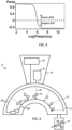
- the first RF frequency is below a threshold frequency and the second RF frequency is above the threshold frequency, thereby to generate dielectrophoretic forces on the particles in opposite directions.
- the dielectrophoretic effect is frequency-dependent, and in this way forces in opposing directions can be alternately applied. This provides an efficient disintegration solution.
- the threshold frequency is for example 1 MHz, so that at least one frequency is below 1 MHz and at least one frequency is above 1 MHz.
- the frequency of the cyclic control signal is for example in the range 0.1 Hz to 1kHz, for example in the range 1 Hz to 100 Hz.
- the oral care device may further comprise a brush head; and a motor for driving the brush head with a vibratory motion with a vibration frequency.
- a biofilm e.g. plaque
- a cleaning agent e.g. water
- the frequency of the cyclic control signal is for example equal to the vibration frequency or a sub-harmonic of the vibration frequency. In this way, forces are applied in opposite directions to the particles of the biofilm by combining the effects of mechanical vibration as well as electromagnetic forces from the RF field.
- positive and negative forces induced by the RF field may be enhanced by synchronization with the brush head vibration.
- the force resulting from the RF field changes from positive to negative (i.e. changes direction) at the same moment that the brush head motion changes direction.
- the force resulting from the RF field and that transmitted to the particle from the brush motion are always in the direction of brush head motion.
- This driving scheme will be thus be even more efficient in vibrating and loosening the particles in the biofilm.
- the vibration frequency is for example in the range 50 Hz to 1 kHz.
- the field generator may be coupled to the brush head for moving with the brush head.
- a particle experiencing a force resulting from the RF field will for example be effectively captured by the force and move as the brush head moves.
- the field generator is for example configured to generate a non-uniform electric field, having a field strength gradient in one or more directions, for generating a force on a polarizable particle along a direction of the gradient.
- a non-uniform field such as this can be used to move electrically polarized particles.
- a polarized or polarizable particle will move along the direction of the field strength gradient due to the non-uniform force experienced at each pole of the particle's electric dipole.
- the field can be configured so as to exhibit field strength gradients which define one or more gradient paths corresponding to directions in which forces are desired to be applied.
- the non-uniform electric field can be used to move electrically polarizable or polarized particles by means of the dielectrophoresis (DEP) effect.
- DEP dielectrophoresis
- the field can be configured so as to exhibit field strength gradients which define one or more gradient paths leading toward locations where those cleaning agent particles are desired to be delivered.
- the system may use electrically polarizable capsules having oral treatment agents contained therein, the electrically polarizable capsules constituting the cleaning agent particles susceptible to the field.
- These capsules can be moved by means of the non-uniform electric field to the desired locations in the mouth.
- the active agent therein may then be deployed at those locations. This might happen without further interaction from the device, e.g. the capsules are water soluble and break down due to interaction with saliva, or it may be triggered by an activation stimulus generated by the device.
- the field generator for example comprises one or more conductive elements, electrically coupled to the controller, and the control signal is an electrical drive signal for electrifying the one or more conductive elements.
- Figure 1 schematically illustrates components of a first example device according to one or more embodiments.
- the device 8 comprises a field generator 16 adapted to generate a first electric field 20 in a space responsive to an input control signal.
- the device further includes a controller 10 adapted to generate the control signal, to control generation of the electric field 20 in the space.
- the field is for imparting a force upon particles of a biofilm, or other polarizable particles such as cleaning agent particles, susceptible to the field.
- the field generator 16 is for operation in a mouth of a user.
- the direction of the force applied to the particles of the biofilm preferably includes at least a component which is non-normal to the tooth surface, thereby providing a lateral force.
- the field generator comprises two field generation arrangements or portions 16a, 16b, each comprising a first 18a and second 18b conductive body which are arranged to receive the control signal from the controller 10.
- Each generates a respective local field 20 between the respective conductive bodies, for applying forces to particles in a local area.
- a single field generation arrangement could be provided, arranged to generate a field over a single area.
- the device 8 comprises a support body 12 which carries or integrates the field generator 16a, 16b.
- the field generator is carried on a support surface 13 of the support body or is integrated beneath the support surface.
- the controller 10 may also be carried by or integrated in the support body 12, or it may be separate from the support body and electrically coupled or coupleable with the field generator 16 of the support body.
- the device 8 may further comprise a handle or body portion to which the support body 12 couples or attaches, and which integrates the controller 10.
- each field generation arrangement 16a, 16b of the field generator 16 comprises a respective pair of electrodes 18a, 18b, separated by a space, and arranged to receive a voltage supply from the controller 10 causing charging of the electrodes. This induces an electric field 20 between the electrodes.
- the particles susceptible to the field have a force applied to them.
- the invention can be implemented in a range of different oral care devices such as mouthpiece devices, toothbrushes, interdental cleaning devices, flossing devices, and oral irrigator devices.
- Figure 1 shows one example in the form a mouthpiece device having an arcuate support body 12 with a support surface 13.
- the arcuate shape permits the mouthpiece to be received in an oral cavity of the user. It may be shaped to conform to the geometry or contours of a user's mouth (e.g. a specific user or a typical user). It may have upper and lower surfaces.
- the conductive elements of the field generator 16 may be carried by the support surface 13 of the support body 12.
- control signal generated by the controller 10 is dynamically varied as a function of time, to dynamically control a force exerted on the susceptible particles.
- the control signal may be varied over time to dynamically control the way particles in the generated electric field are polarized.
- the polarization is dependent on frequency.
- the frequency can for example be controlled to cause the force to change in magnitude and sign.
- the field generator 16 is thereby configured to generate a non-uniform field 20 (non-uniform field strength) having a field strength gradient in one or more directions, for apply a force to the particles along a direction of the gradient.
- a non-uniform field such as this can apply a force to electrically polarizable or polarized particles.
- a polarized particle will have a force applied along the direction of the field strength gradient due to the non-uniform force experienced at each pole of the particle's electric dipole.
- a non-uniform electric field can in this way be used to apply a force to electrically polarizable or polarized particles by means of the dielectrophoresis (DEP) effect.
- DEP dielectrophoresis
- the electrodes 18 of each pair differ in respective size. This is just one way to create a non-uniform field pattern.
- the first electrode 18a in Figure 1 is longer than the second electrode. It may be longer in a dimension perpendicular the direction of the separation between the pair of electrodes for example.
- an asymmetric pair of electrodes is provided.
- one electrode 18a which spans a larger distance than the other 18b along a direction perpendicular their separation, this results in a field which is more spatially spread on one side of the separation space than the other, with the result that there is a net force toward the smaller electrode.
- each electrode 18a, 18b of the pair may have a respective electrically chargeable or active area for generating the electric field 20 in the space between the pair when electrically charged, and wherein the electrically chargeable or active areas of the two electrodes may differ in size.
- the parts of the electrodes 18a, 18b which become charged and contribute to the field may differ in area between the electrodes. They may additionally or alternatively differ in dimensional extension along a direction perpendicular to a direction of the separation between the electrodes.
- Electrodes of different lengths or areas is not the only way to create a spatially non-uniform field.
- An alternative means for instance is to provide a pair of electrodes of the same length, spaced from one another, but disposed at an oblique angle with respect to one another. More generally, any electrode arrangement can be used in which the potential gradient between the electrodes varies spatially, rather than a simple parallel plate arrangement which generates a uniform field.
- the electrodes may be plate electrodes, but equally one of the electrodes of each pair of electrodes may be a flat plate electrode, and the other electrode may have a different, round-ended shape, so that its electrically active area extends around side surfaces of the electrode.
- FIG. 2 shows an example pair of electrodes 18a, 18b, separated by a space, D.
- One electrode 18a is negatively charged, the other 18b is positively charged, thereby inducing an electric field between them.
- the first electrode 18a is longer than the second electrode 18b in a dimension perpendicular the direction of separation, D, between the electrodes.
- This has the effect that for a polarized or polarizable particle 22 located within the field, there is a net force on the particle toward the smaller electrode 18b, along the direction of separation between the electrodes. This is because in the non-uniform field, the particle is not uniformly polarized, since different parts of the particle are in field regions of differing field strength.
- the particle is an electrically polarizable particle
- the pair of electrodes is driven with an alternating potential to create an alternating field
- DEP dielectrophoresis
- the electric field 20 polarizes the particle 22, so that the poles experience a force along the field lines, which can be either attractive or repulsive according to the orientation on the dipole. Since the field 20 is non-uniform, and at this frequency the particle polarizes in phase with the RF field (positive DEP) the pole experiencing the greatest electric field will dominate over the other, and the particle will move in that direction. At other frequencies where there is negative DEP, the particle will of course move in the opposite direction.
- Bio particles in the biofilm or other polarizable particles such as cleaning agent particles may have a force applied and hence move (if and when they are free to do so) under the influence of this dielectrophoretic force.
- this dielectrophoretic force may be used to remove plaque optimally.
- Plaque normally consists of bacterial micro-colonies embedded in an exopolysaccharide (EPS) matrix.
- EPS exopolysaccharide
- the invention is based on the realization that these characteristics of the dielectrophoretic force can be exploited in an oral care device, such as a toothbrush, with RF field generation, to improve the movement of particles or the disintegration of a biofilm, for the cleaning of teeth or improving oral health.
- the invention makes use of the intermittent generation of an electric field at combinations of RF frequencies, and these may optionally additionally be synchronized with the motion frequencies and amplitudes of an electric vibrating toothbrush head.
- One possible purpose is to facilitate removal of plaque by breaking connections between particles (cells or colonies) and EPS. Particles (cells or colonies) may additionally be moved out of hard-to-reach areas, e.g. out of periodontal pockets. Movement of cleaning agent particles may also be controlled.
- the controller 10 for example provides an alternating drive signal between the electrodes 18a, 18b of each pair of electrodes, to thereby induce a (non-uniform) alternating field between each pair of electrodes.
- An RF field can be used to perform an oral cleaning function and/or it may be used to performing the function of guiding movement of the particles.
- RF fields can be used for example with frequencies anywhere in the range of 10 kHz - 100 MHz.
- a preferred frequency range may be 500 kHz - 30 MHz.
- DEP dielectrophoresis
- Figure 4 shows an example device in the form of a mouthpiece unit in more detail than the schematic example of Figure 1 .
- the device again comprises a support body 12 having a support surface 13, the support body for being received in an oral cavity of a user.
- the support body is coupled to a handle portion 34 which houses the controller 10.
- the handle portion in this example is shown with the optional additional feature of a local reservoir 32 for holding cleaning agent particles including an active agent or substance for delivery in the mouth. It is fluidly connected to a deployment surface of the device, e.g. via one or more fluid passages, to enable particles to be received on the surface in use ready for delivery.
- the device may be adapted to releasably couple or dock with an external reservoir 36, such as a bottle or other receptacle.
- an external reservoir 36 such as a bottle or other receptacle.
- particles can be loaded from the reservoir onto the support surface 13 ready to de delivered in the mouth.
- the device comprises a first 18a and second 18b arcuate electrode, the electrodes spaced from one another radially (along a radial dimension of the arcuate or semi-annular support body).
- the first electrode 18a extends proximal to, and follows the outline of, an outer circumferential edge of the body 12.
- the second electrode 18b extends proximal to and follows the outline of an inner circumferential edge of the body 12.
- the two electrodes are connected to a voltage source 11, and supplied with opposing polarity voltages.
- An alternating voltage is used to generate an RF field.
- a separate voltage source 11 and controller 10 are shown in Figure 4 .
- the controller controls the drive scheme of the voltage source.
- the controller 10 may provide the voltage source.
- the pair of electrodes 18a, 18b, in combination with the voltage source, provides a field generator 16.
- electrically polarizable particles 22 can be driven to migrate along field gradient lines, e.g. toward the smaller, inner electrode 18b.
- the field gradient direction in this case is the radial direction, toward the second electrode, and the gradient is uniform along a circumferential direction.
- forces are directed towards the second electrode.
- forces can be applied to the static particles in the biofilm to be removed, thereby to disintegrate the biofilm.
- Figure 5 shows a further example oral cleaning device 8.
- This embodiment may be the same in all respects as that of Figure 4 apart from the additional provision to each of the first 18a and second 18b electrodes of radially protruding electrode nodes 21.
- the first electrode 18a comprises a first set of nodes 21a, spaced along the length of the electrode, facing toward the second electrode 18b
- the second electrode 18b comprises a second set of nodes 21b, spaced apart and facing the first electrode.
- the first and second sets of nodes are circumferentially offset from one another, so that each node radially faces a node-free space on the other opposing electrode.
- the nodes 21a, 21b allow for defining different force directions, for example including a lateral component.
- more localized particle collection points may be defined across the support surface 13, permitting guidance of particles to more specific locations in the mouth when in use.
- Figure 6 shows a further example oral cleaning device 8 which is again similar in all respects to the embodiment of Figures 4 and 5 apart from the configuration of the first and second electrodes.
- the first 18a and second 18b electrodes are provided in the form of arcuate interdigitated electrodes.
- the first 18a and second 18b electrodes each comprise a set of protruding electrode fingers 19a, 19b. These effectively perform the same function as the nodes 21 of Figure 5 , in providing more spatially defined particle collection points.
- the electrodes 18a, 18b are driven with an alternating drive signal, to create an alternating field, the field strength gradients are directed toward the electrode fingers 19a, 19b.
- the first electrode 18a comprises a first set of fingers 19a, spaced along the length of the electrode, facing toward the second electrode 18b
- the second electrode 18b comprises a second set of fingers 19b, spaced apart and facing the first electrode.
- the first and second sets of electrode fingers are circumferentially offset from one another, so that each finger radially faces a free space on the other opposing electrode.
- electrode fingers over nodes is that field strength gradients are directed toward their distal (free) ends, and the finger elements 19 can be made as long (in the radial direction) as desired. Thus, it is possible to more flexibly define the force pattern (and for example the locations for particle collection).
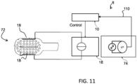
- Figure 7 shows an oral care device 8 in the form of a toothbrush and shows the RF field generator 16 and its controller 10 for generating the input control signal "Control", to control generation of the electric field by application to the electrodes 18.
- the electric field imparts a force upon particles forming a biofilm to be removed by the oral care device or on cleaning agent particles.
- the oral care device in this example comprises an electric toothbrush with a brush head 72 and a motor and drive train 74 for driving the brush head with a vibratory motion with a vibration frequency.
- the controller 16 has suitable control electronics (such as a Schmitt trigger) to be able to switch at least between two different frequencies or to apply a duty cycle to a single frequency. In all cases, there will be a cyclic control signal for intermittent generation of an electric field of a first RF frequency, and this control signal may additionally control the generation at one or more further frequencies.
- the controller 16 applies two different frequencies of RF field, either side of the DEP switching point discussed above.
- the conventional RF driving scheme (of RF driving with a single frequency) is adapted to make better use of the DEP.
- the RF electrodes are driven using two RF frequencies, one each side of a threshold, which is a transition point between attraction and repelling of polarized or polarizable particles.
- the DEP driving force shown in Figure 3 is explained above as having a transition frequency of around 1 MHz. Suitable driving frequencies may then be 0.5 MHz and 5 MHz, or 100 kHz and 10 MHz etc.
- the switching between the frequencies should occur fairly rapidly, for example every few seconds or several times per second or even several hundred times per second, hence with a frequency between 0.1 Hz and 1kHz.
- This force direction reversal is of particular interest for applying force directly to the particles of the biofilm.
- the force on the bio particles of the biofilm in the mouth will reverse in direction at this switching frequency.
- the particles will thereby be vibrated and loosened more effectively than if the force is maintained in the same direction.
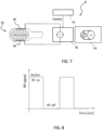
- the controller 16 applies only one frequency of RF field but with intermittent application of the field. Furthermore, the frequency of the cyclic control signal providing this intermittent field generation is preferably linked to the vibration in the brush, to make better use of the DEP.
- a single RF frequency may be used, but it is turned on and off with a period synchronized to the frequency (or a sub-harmonic of the frequency) of the brush head motion.
- Figure 8 shows the cyclic control signal with a 50% duty cycle (as one possible example - other duty cycles may be used), and one period corresponds to one oscillation period of the vibratory brush head motion. While the RF field is activated, there is a force (the DEP force) on the polarizable particles, whilst when the duty cycle causes the RF field to de-activate this force is zero.
- this may be used to control the movement of the particles.
- the RF field is displaced in space (following the brush motion, as the electrodes are mounted on the brush head).
- a particle experiencing a force e.g. from the DEP
- the particles may be captured and moved in one part of the duty cycle (where the brush head moves in one direction) but are released in the other (where the brush head moves in the opposite direction). As a consequence, the particles may be repeatedly moved in the same direction instead of being moved backwards and forwards.
- Figure 10 shows a brush head 72 with a set of bristles 100, for moving particles in the manner represented in Figure 9 .
- the vibration frequency can be rather high (around a few 100 Hz) this results in very fast motion of particles in one direction. This can be particularly useful to remove bacteria out of subgingival areas, especially out of deeper periodontal pockets. Such pockets can be for example 5mm deep, and bacteria are often loosely attached or even floating in the pocket fluid.
- the DEP force may be used to pull bacterial cells out of the pocket when synchronized with the brush sweep up.
- the DEP force may be alternatively synchronized with the sweep down or the sweep up.
- the controller may implement a driving scheme with switching between two RF frequencies or applying a frequency sweep (as explained above for the first example), but synchronized with the vibration frequency of the brush (as explained above for the second example).
- the known RF driving scheme is adapted to provide the cyclic control, but also in a manner to provide synchronization with the vibration in the brush to make better use of the DEP.
- the driving switches between at least two RF frequencies to induce positive and negative DEP at the frequency (or a sub-harmonic of the frequency) of the brush head motion.
- the DEP force on the particles thereby changes from positive to negative at the same moment that the brush head motion changes direction. If this is correctly synchronized, the force of the DEP and also that transmitted to the captured particle from the brush motion are always in the direction of brush head motion.
- Figure 11 shows the required modification to the system of Figure 7 .
- the drive train current or voltage or amplitude signal is used as synchronization and control signal 110 for the controller 10.
- the invention relates specifically to the control of the RF field and the forces that result, and these forces may be used to act directly on particles of the biofilm to disintegrate the biofilm, or they may be used to control the delivery of cleaning agent particles.
- the cleaning agent particles for example comprise oral cleaning or treatment agents such as fluoride, whitening agents, mouthwash or anti-microbially effective particles.
- the delivered agent can also include Catalytic Antimicrobial Robots (CARs) in a polarizable carrier capsule. These exploit iron oxide nanoparticles with catalytic functionality to (i) generate bactericidal free radicals, (ii) break down the biofilm exopolysaccharide (EPS) matrix, and (iii) remove the fragmented biofilm debris via electric field gradient-driven robotic assemblies in a controlled manner, preventing biofilm regrowth. Any other substance for an oral cleaning or treatment purpose can also be considered.
- CARs Catalytic Antimicrobial Robots
- whitening agents need to be homogeneously spread across surfaces of the teeth, and antimicrobial particles need to be spread evenly across portions of the gums.
- delivering the agents to the parts of the mouth where they are needed is difficult and inefficient, which reduces their efficacy and causes inconvenience for a user.
- the electric field may therefore additionally be used to manipulate the distribution of particles comprising oral treatment agents within the mouth.
- the particles manipulated by the field may themselves be particles of an oral treatment agent, or may be carrier particles, which contain within them a treatment agent to be deployed.
- the particles may be capsules for containing therein a treatment agent.
- the particles may then be guided to move due to a force induced on the particles by the field.
- the particles may be guided to move along or across the surface 13 of the support body 12 in some cases to thereby transport them to the required location in the mouth.
- the invention may be used in a system which only uses the RF for controlled delivery of cleaning agent particles.
- the invention may instead be used in a system which only uses the RF field for direct application of force to the particles of the biofilm.
- the controller may then be selectively controllable between at least two different modes:
- the device may be configured with the functionality of triggering an activation of delivered particles.
- This activation may be a chemical or physical reaction process, or a process of breaking down particles to trigger release of their contents. This step may be performed subsequent to moving the particles to the desired locations in the mouth for example.
- the device may further comprise a particle activator adapted to generate a physical stimulus for stimulating an activation event of the agent particles.
- the particle activator is composed of the same or different components to the field generator.
- the particle activator may be provided by the field generator in some example, or may be a formed by a separate set of one or more components.
- the stimulus may, by way of non-limiting example, include at least one of: a generated field (electrical and/or magnetic stimulus), a heat stimulus, and an acoustic stimulus.
- a tooth brushing mouthpiece and an electric toothbrush examples are presented above.
- the invention may however also be applied in other oral cleaning devices such as irrigators or flossing devices.
- controllers can be implemented in numerous ways, with software and/or hardware, to perform the various functions required.
- a processor is one example of a controller which employs one or more microprocessors that may be programmed using software (e.g., microcode) to perform the required functions.
- a controller may however be implemented with or without employing a processor, and also may be implemented as a combination of dedicated hardware to perform some functions and a processor (e.g., one or more programmed microprocessors and associated circuitry) to perform other functions.
- controller components that may be employed in various embodiments of the present disclosure include, but are not limited to, conventional microprocessors, application specific integrated circuits (ASICs), and field-programmable gate arrays (FPGAs).
- ASICs application specific integrated circuits
- FPGAs field-programmable gate arrays
- a processor or controller may be associated with one or more storage media such as volatile and non-volatile computer memory such as RAM, PROM, EPROM, and EEPROM.
- the storage media may be encoded with one or more programs that, when executed on one or more processors and/or controllers, perform the required functions.
- Various storage media may be fixed within a processor or controller or may be transportable, such that the one or more programs stored thereon can be loaded into a processor or controller.
- a computer program may be stored/distributed on a suitable medium, such as an optical storage medium or a solid-state medium supplied together with or as part of other hardware, but may also be distributed in other forms, such as via the Internet or other wired or wireless telecommunication systems.
- a suitable medium such as an optical storage medium or a solid-state medium supplied together with or as part of other hardware, but may also be distributed in other forms, such as via the Internet or other wired or wireless telecommunication systems.
- a controller may however be implemented with or without employing a processor, and also may be implemented as a combination of dedicated hardware to perform some functions and a processor (e.g., one or more programmed microprocessors and associated circuitry) to perform other functions.
- a processor e.g., one or more programmed microprocessors and associated circuitry
- controller components that may be employed in various embodiments of the present disclosure include, but are not limited to, conventional microprocessors, application specific integrated circuits (ASICs), and field-programmable gate arrays (FPGAs).
- ASICs application specific integrated circuits
- FPGAs field-programmable gate arrays
- a processor or controller may be associated with one or more storage media such as volatile and non-volatile computer memory such as RAM, PROM, EPROM, and EEPROM.
- the storage media may be encoded with one or more programs that, when executed on one or more processors and/or controllers, perform the required functions.
- Various storage media may be fixed within a processor or controller or may be transportable, such that the one or more programs stored thereon can be loaded into a processor or controller.
- a computer program may be stored/distributed on a suitable medium, such as an optical storage medium or a solid-state medium supplied together with or as part of other hardware, but may also be distributed in other forms, such as via the Internet or other wired or wireless telecommunication systems.
- a suitable medium such as an optical storage medium or a solid-state medium supplied together with or as part of other hardware, but may also be distributed in other forms, such as via the Internet or other wired or wireless telecommunication systems.
Landscapes
- Health & Medical Sciences (AREA)
- Life Sciences & Earth Sciences (AREA)
- Animal Behavior & Ethology (AREA)
- General Health & Medical Sciences (AREA)
- Public Health (AREA)
- Veterinary Medicine (AREA)
- Dentistry (AREA)
- Epidemiology (AREA)
- Biomedical Technology (AREA)
- Engineering & Computer Science (AREA)
- Nuclear Medicine, Radiotherapy & Molecular Imaging (AREA)
- Radiology & Medical Imaging (AREA)
- Acoustics & Sound (AREA)
- Oral & Maxillofacial Surgery (AREA)
- Physics & Mathematics (AREA)
- Brushes (AREA)
- Dental Tools And Instruments Or Auxiliary Dental Instruments (AREA)
- Cosmetics (AREA)
Claims (10)
- Mundpflegevorrichtung (8), umfassend:
einen Feldgenerator (16), der so ausgelegt ist, dass er als Reaktion auf ein Eingabesteuersignal ein elektrisches Feld (20) im Mund eines Benutzers erzeugt:ein Steuergerät (10), das so ausgelegt ist, dass es das Eingangssteuersignal erzeugt, um die Erzeugung des elektrischen Feldes zu steuern, wobei das elektrische Feld dient, um eine Kraft auf Partikel (22) auszuüben, die einen Biofilm bilden, der durch die Mundpflegevorrichtung bzw. durch die Reinigungsmittelpartikel entfernt werden soll,dadurch gekennzeichnet, dass das Steuergerät ausgelegt ist, um ein zyklisches Steuersignal zur Erzeugung des elektrischen Feldes bei einer ersten HF-Frequenz und bei einer zweiten HF-Frequenz zu erzeugen, wobei die erste HF-Frequenz unter einer Schwellenfrequenz liegt und die zweite HF-Frequenz über der Schwellenfrequenz liegt, um dadurch dielektrophoretische Kräfte auf die Partikel in entgegengesetzte Richtungen zu erzeugen, wobei das zyklische Steuersignal für Folgendes dient:Erzeugen eines Frequenzwechsels zwischen der ersten HF-Frequenz und der zweiten HF-Frequenz; oderErzeugen eines Frequenzsweeps zwischen der ersten HF-Frequenz und der zweiten HF-Frequenz. - Mundpflegevorrichtung nach Anspruch 1, wobei die Schwellenfrequenz 1 MHz beträgt.
- Mundpflegevorrichtung nach Anspruch 1 oder 2, wobei die Frequenz des zyklischen Steuersignals im Bereich von 0,1 Hz bis 1 kHz, beispielsweise im Bereich von 1 Hz bis 100 Hz liegt.
- Mundpflegevorrichtung nach einem der Ansprüche 1 bis 3, weiterhin umfassend:einen Bürstenkopf; undeinen Motor zum Antreiben des Bürstenkopfes mit einer Vibrationsbewegung mit einer Vibrationsfrequenz, die mit dem zyklischen Steuersignal synchronisiert ist.
- Mundpflegevorrichtung nach Anspruch 4, wobei die Frequenz des zyklischen Steuersignals gleich der Vibrationsfrequenz oder einer Subharmonischen der Vibrationsfrequenz ist.
- Mundpflegevorrichtung nach Anspruch 5, wobei die Vibrationsfrequenz im Bereich von 50 Hz bis 1 kHz liegt.
- Mundpflegevorrichtung nach Anspruch 4, 5 oder 6, wobei der Feldgenerator (16) mit dem Bürstenkopf gekoppelt ist, um sich mit dem Bürstenkopf zu bewegen.
- Mundpflegevorrichtung nach einem der Ansprüche 1 bis 7, wobei der Feldgenerator so konfiguriert ist, dass er ein ungleichmäßiges elektrisches Feld mit einem Feldstärkegradienten in einer oder mehreren Richtungen erzeugt, um eine Kraft entlang einer Richtung des Gradienten zu erzeugen.
- Mundpflegevorrichtung nach einem der Ansprüche 1 bis 8, wobei der Feldgenerator (16) ein oder mehrere leitfähige Elemente (18) umfasst, die elektrisch mit dem Steuergerät (10) gekoppelt sind, und wobei das Steuersignal ein elektrisches Antriebssignal zum Elektrifizieren des einen oder der mehreren leitenden Elemente ist.
- Computerprogrammprodukt mit Computerprogrammcode, wobei der Computerprogrammcode auf einem Prozessor oder Computer ausführbar ist, wobei, wenn der Prozessor oder Computer operativ mit dem Feldgenerator der Mundpflegevorrichtung nach Anspruch 1 gekoppelt ist, der Code so konfiguriert ist, dass er den Prozessor veranlasst, ein Verfahren zum Steuern der Mundpflegevorrichtung auszuführen, das Folgendes umfasst:Erzeugen eines Steuersignals, um die Erzeugung eines elektrischen Feldes im Mund eines Benutzers zu steuern, wobei das elektrische Feld dient, um eine Kraft auf Partikel (22) auszuüben, die einen Biofilm bilden, der durch die Mundpflegevorrichtung bzw. durch Reinigungsmittelpartikel entfernt werden soll,dadurch gekennzeichnet, dass das Steuersignal ein zyklisches Steuersignal zur Erzeugung des elektrischen Feldes bei einer ersten HF-Frequenz und bei einer zweiten HF-Frequenz umfasst, wobei die erste HF-Frequenz unter einer Schwellenfrequenz liegt und die zweite HF-Frequenz über der Schwellenfrequenz liegt, um dadurch dielektrophoretische Kräfte auf die Partikel in entgegengesetzten Richtungen zu erzeugen, wobei das zyklische Steuersignal für Folgendes dient:Erzeugen eines Frequenzwechsels zwischen der ersten HF-Frequenz und der zweiten HF-Frequenz; oderErzeugen eines Frequenzsweeps zwischen der ersten HF-Frequenz und der zweiten HF-Frequenz.
Applications Claiming Priority (2)
| Application Number | Priority Date | Filing Date | Title |
|---|---|---|---|
| EP20176970.0A EP3915437A1 (de) | 2020-05-28 | 2020-05-28 | Mundpflegevorrichtung und -verfahren |
| PCT/EP2021/063408 WO2021239555A1 (en) | 2020-05-28 | 2021-05-20 | Oral care device and method |
Publications (3)
| Publication Number | Publication Date |
|---|---|
| EP4157035A1 EP4157035A1 (de) | 2023-04-05 |
| EP4157035C0 EP4157035C0 (de) | 2023-12-06 |
| EP4157035B1 true EP4157035B1 (de) | 2023-12-06 |
Family
ID=70918249
Family Applications (2)
| Application Number | Title | Priority Date | Filing Date |
|---|---|---|---|
| EP20176970.0A Withdrawn EP3915437A1 (de) | 2020-05-28 | 2020-05-28 | Mundpflegevorrichtung und -verfahren |
| EP21726413.4A Active EP4157035B1 (de) | 2020-05-28 | 2021-05-20 | Mundpflegevorrichtung und -verfahren |
Family Applications Before (1)
| Application Number | Title | Priority Date | Filing Date |
|---|---|---|---|
| EP20176970.0A Withdrawn EP3915437A1 (de) | 2020-05-28 | 2020-05-28 | Mundpflegevorrichtung und -verfahren |
Country Status (5)
| Country | Link |
|---|---|
| US (1) | US20230191143A1 (de) |
| EP (2) | EP3915437A1 (de) |
| JP (1) | JP7610785B2 (de) |
| CN (1) | CN115916003B (de) |
| WO (1) | WO2021239555A1 (de) |
Families Citing this family (3)
| Publication number | Priority date | Publication date | Assignee | Title |
|---|---|---|---|---|
| US11141254B2 (en) * | 2018-08-10 | 2021-10-12 | Sdc U.S. Smilepay Spv | Mouthpiece for teeth whitening |
| KR20250150025A (ko) * | 2023-02-09 | 2025-10-17 | 라이언 맥마누스 | 바이오필름 교반을 위한 감염 방지 수술 장치 및 방법 |
| IT202400003637A1 (it) | 2024-02-21 | 2025-08-21 | Roberto Taschini | Dispositivo per igienizzare in modo naturale qualsiasi spazzolino da denti |
Citations (4)
| Publication number | Priority date | Publication date | Assignee | Title |
|---|---|---|---|---|
| WO2001030196A1 (en) * | 1999-10-26 | 2001-05-03 | Richter Corporation | Toothbrush |
| JP2001346816A (ja) * | 2000-06-07 | 2001-12-18 | Matsushita Electric Works Ltd | 電動歯ブラシ |
| US20170189149A1 (en) * | 2014-10-27 | 2017-07-06 | TCD Consulting LLC | Ultrasonic tooth cleaning apparatus and method |
| EP3104807B1 (de) * | 2014-10-04 | 2018-12-19 | Brighttonix Medical Ltd. | Vorrichtung zur behandlung der zähne |
Family Cites Families (9)
| Publication number | Priority date | Publication date | Assignee | Title |
|---|---|---|---|---|
| FR2844719B1 (fr) * | 2002-09-24 | 2004-11-19 | Francois Duret | Dispositif electro-chimique pour le blanchiment d'un corps |
| JP4642422B2 (ja) * | 2004-10-05 | 2011-03-02 | ライオン株式会社 | 口腔清掃用具 |
| WO2007121760A1 (en) * | 2006-04-20 | 2007-11-01 | Remedent Nv | Method and device for enhancing the treatment of teeth and gums |
| JP2008119154A (ja) * | 2006-11-10 | 2008-05-29 | Matsushita Electric Ind Co Ltd | 口腔内清掃器具 |
| WO2009047365A1 (en) * | 2007-10-12 | 2009-04-16 | Capsulution Nanoscience Ag | Drug delivery system |
| DE102011079577A1 (de) * | 2011-07-21 | 2013-01-24 | Siemens Aktiengesellschaft | Oralspule für ein Magnetresonanztomographiesystem |
| EP3220851B1 (de) * | 2014-11-21 | 2021-09-15 | Koninklijke Philips N.V. | Verwendung eines resonanten systems zur automatischen modifizierung der leistung (amplitude) eines mundpflegegeräts nach verwendung im mund |
| US10201701B2 (en) * | 2015-03-29 | 2019-02-12 | Home Skinovations Ltd. | Oral electrical cleaning device |
| WO2020081720A1 (en) * | 2018-10-16 | 2020-04-23 | Yale University | Electronic system for capture and characterization of particles |
-
2020
- 2020-05-28 EP EP20176970.0A patent/EP3915437A1/de not_active Withdrawn
-
2021
- 2021-05-20 WO PCT/EP2021/063408 patent/WO2021239555A1/en not_active Ceased
- 2021-05-20 CN CN202180037850.7A patent/CN115916003B/zh active Active
- 2021-05-20 JP JP2022565567A patent/JP7610785B2/ja active Active
- 2021-05-20 US US17/925,335 patent/US20230191143A1/en active Pending
- 2021-05-20 EP EP21726413.4A patent/EP4157035B1/de active Active
Patent Citations (4)
| Publication number | Priority date | Publication date | Assignee | Title |
|---|---|---|---|---|
| WO2001030196A1 (en) * | 1999-10-26 | 2001-05-03 | Richter Corporation | Toothbrush |
| JP2001346816A (ja) * | 2000-06-07 | 2001-12-18 | Matsushita Electric Works Ltd | 電動歯ブラシ |
| EP3104807B1 (de) * | 2014-10-04 | 2018-12-19 | Brighttonix Medical Ltd. | Vorrichtung zur behandlung der zähne |
| US20170189149A1 (en) * | 2014-10-27 | 2017-07-06 | TCD Consulting LLC | Ultrasonic tooth cleaning apparatus and method |
Also Published As
| Publication number | Publication date |
|---|---|
| CN115916003B (zh) | 2025-04-08 |
| US20230191143A1 (en) | 2023-06-22 |
| EP4157035C0 (de) | 2023-12-06 |
| EP3915437A1 (de) | 2021-12-01 |
| CN115916003A (zh) | 2023-04-04 |
| EP4157035A1 (de) | 2023-04-05 |
| WO2021239555A1 (en) | 2021-12-02 |
| JP2023528169A (ja) | 2023-07-04 |
| JP7610785B2 (ja) | 2025-01-09 |
Similar Documents
| Publication | Publication Date | Title |
|---|---|---|
| EP4157035B1 (de) | Mundpflegevorrichtung und -verfahren | |
| JP5437531B2 (ja) | 口腔清掃装置及び口腔清掃装置のヘッド部分 | |
| KR101633564B1 (ko) | 자동 모드 선택을 갖는 구강 케어 장치 | |
| JP2014054514A (ja) | 美容器具 | |
| CN107206249A (zh) | 用于开放性伤口的超声治疗的装置 | |
| EP4432974B1 (de) | Systeme und verfahren zur steuerung der kraftabgriffsbewegung | |
| US20230190435A1 (en) | Oral care device and method | |
| US20250009491A1 (en) | Optimal parameters for sweeping and power tapping motions | |
| KR102841620B1 (ko) | 전기장 및 진동을 이용하는 구강관리장치 | |
| EP4432975B1 (de) | Resonatoranordnung und elektrische zahnbürste mit einem solchen resonator. | |
| US20240366337A1 (en) | System for cleaning a root canal of a tooth, and related components and methods | |
| KR20030011741A (ko) | 비 접촉 칫솔 | |
| KR102826547B9 (ko) | 전기장 및 진동을 이용하는 구강세정장치 | |
| EP4704756A1 (de) | System zur reinigung eines zahnwurzelkanals und zugehörige komponenten und verfahren | |
| JP2016043035A (ja) | イオン導入機能付き振動美容器 | |
| JPWO2021239557A5 (de) | ||
| JP2001224605A (ja) | 歯周ポケット用清掃具 |
Legal Events
| Date | Code | Title | Description |
|---|---|---|---|
| STAA | Information on the status of an ep patent application or granted ep patent |
Free format text: STATUS: UNKNOWN |
|
| STAA | Information on the status of an ep patent application or granted ep patent |
Free format text: STATUS: THE INTERNATIONAL PUBLICATION HAS BEEN MADE |
|
| PUAI | Public reference made under article 153(3) epc to a published international application that has entered the european phase |
Free format text: ORIGINAL CODE: 0009012 |
|
| STAA | Information on the status of an ep patent application or granted ep patent |
Free format text: STATUS: REQUEST FOR EXAMINATION WAS MADE |
|
| 17P | Request for examination filed |
Effective date: 20230102 |
|
| AK | Designated contracting states |
Kind code of ref document: A1 Designated state(s): AL AT BE BG CH CY CZ DE DK EE ES FI FR GB GR HR HU IE IS IT LI LT LU LV MC MK MT NL NO PL PT RO RS SE SI SK SM TR |
|
| GRAP | Despatch of communication of intention to grant a patent |
Free format text: ORIGINAL CODE: EPIDOSNIGR1 |
|
| STAA | Information on the status of an ep patent application or granted ep patent |
Free format text: STATUS: GRANT OF PATENT IS INTENDED |
|
| DAV | Request for validation of the european patent (deleted) | ||
| DAX | Request for extension of the european patent (deleted) | ||
| INTG | Intention to grant announced |
Effective date: 20230629 |
|
| GRAS | Grant fee paid |
Free format text: ORIGINAL CODE: EPIDOSNIGR3 |
|
| GRAA | (expected) grant |
Free format text: ORIGINAL CODE: 0009210 |
|
| STAA | Information on the status of an ep patent application or granted ep patent |
Free format text: STATUS: THE PATENT HAS BEEN GRANTED |
|
| AK | Designated contracting states |
Kind code of ref document: B1 Designated state(s): AL AT BE BG CH CY CZ DE DK EE ES FI FR GB GR HR HU IE IS IT LI LT LU LV MC MK MT NL NO PL PT RO RS SE SI SK SM TR |
|
| REG | Reference to a national code |
Ref country code: GB Ref legal event code: FG4D |
|
| REG | Reference to a national code |
Ref country code: CH Ref legal event code: EP |
|
| REG | Reference to a national code |
Ref country code: DE Ref legal event code: R096 Ref document number: 602021007517 Country of ref document: DE |
|
| REG | Reference to a national code |
Ref country code: IE Ref legal event code: FG4D |
|
| U01 | Request for unitary effect filed |
Effective date: 20231206 |
|
| U07 | Unitary effect registered |
Designated state(s): AT BE BG DE DK EE FI FR IT LT LU LV MT NL PT SE SI Effective date: 20231211 |
|
| PG25 | Lapsed in a contracting state [announced via postgrant information from national office to epo] |
Ref country code: GR Free format text: LAPSE BECAUSE OF FAILURE TO SUBMIT A TRANSLATION OF THE DESCRIPTION OR TO PAY THE FEE WITHIN THE PRESCRIBED TIME-LIMIT Effective date: 20240307 |
|
| PG25 | Lapsed in a contracting state [announced via postgrant information from national office to epo] |
Ref country code: ES Free format text: LAPSE BECAUSE OF FAILURE TO SUBMIT A TRANSLATION OF THE DESCRIPTION OR TO PAY THE FEE WITHIN THE PRESCRIBED TIME-LIMIT Effective date: 20231206 |
|
| PG25 | Lapsed in a contracting state [announced via postgrant information from national office to epo] |
Ref country code: GR Free format text: LAPSE BECAUSE OF FAILURE TO SUBMIT A TRANSLATION OF THE DESCRIPTION OR TO PAY THE FEE WITHIN THE PRESCRIBED TIME-LIMIT Effective date: 20240307 Ref country code: ES Free format text: LAPSE BECAUSE OF FAILURE TO SUBMIT A TRANSLATION OF THE DESCRIPTION OR TO PAY THE FEE WITHIN THE PRESCRIBED TIME-LIMIT Effective date: 20231206 |
|
| PG25 | Lapsed in a contracting state [announced via postgrant information from national office to epo] |
Ref country code: RS Free format text: LAPSE BECAUSE OF FAILURE TO SUBMIT A TRANSLATION OF THE DESCRIPTION OR TO PAY THE FEE WITHIN THE PRESCRIBED TIME-LIMIT Effective date: 20231206 Ref country code: NO Free format text: LAPSE BECAUSE OF FAILURE TO SUBMIT A TRANSLATION OF THE DESCRIPTION OR TO PAY THE FEE WITHIN THE PRESCRIBED TIME-LIMIT Effective date: 20240306 Ref country code: HR Free format text: LAPSE BECAUSE OF FAILURE TO SUBMIT A TRANSLATION OF THE DESCRIPTION OR TO PAY THE FEE WITHIN THE PRESCRIBED TIME-LIMIT Effective date: 20231206 |
|
| PG25 | Lapsed in a contracting state [announced via postgrant information from national office to epo] |
Ref country code: IS Free format text: LAPSE BECAUSE OF FAILURE TO SUBMIT A TRANSLATION OF THE DESCRIPTION OR TO PAY THE FEE WITHIN THE PRESCRIBED TIME-LIMIT Effective date: 20240406 |
|
| U20 | Renewal fee for the european patent with unitary effect paid |
Year of fee payment: 4 Effective date: 20240531 |
|
| PG25 | Lapsed in a contracting state [announced via postgrant information from national office to epo] |
Ref country code: CZ Free format text: LAPSE BECAUSE OF FAILURE TO SUBMIT A TRANSLATION OF THE DESCRIPTION OR TO PAY THE FEE WITHIN THE PRESCRIBED TIME-LIMIT Effective date: 20231206 |
|
| PG25 | Lapsed in a contracting state [announced via postgrant information from national office to epo] |
Ref country code: SK Free format text: LAPSE BECAUSE OF FAILURE TO SUBMIT A TRANSLATION OF THE DESCRIPTION OR TO PAY THE FEE WITHIN THE PRESCRIBED TIME-LIMIT Effective date: 20231206 |
|
| PG25 | Lapsed in a contracting state [announced via postgrant information from national office to epo] |
Ref country code: SM Free format text: LAPSE BECAUSE OF FAILURE TO SUBMIT A TRANSLATION OF THE DESCRIPTION OR TO PAY THE FEE WITHIN THE PRESCRIBED TIME-LIMIT Effective date: 20231206 Ref country code: SK Free format text: LAPSE BECAUSE OF FAILURE TO SUBMIT A TRANSLATION OF THE DESCRIPTION OR TO PAY THE FEE WITHIN THE PRESCRIBED TIME-LIMIT Effective date: 20231206 Ref country code: RO Free format text: LAPSE BECAUSE OF FAILURE TO SUBMIT A TRANSLATION OF THE DESCRIPTION OR TO PAY THE FEE WITHIN THE PRESCRIBED TIME-LIMIT Effective date: 20231206 Ref country code: IS Free format text: LAPSE BECAUSE OF FAILURE TO SUBMIT A TRANSLATION OF THE DESCRIPTION OR TO PAY THE FEE WITHIN THE PRESCRIBED TIME-LIMIT Effective date: 20240406 Ref country code: CZ Free format text: LAPSE BECAUSE OF FAILURE TO SUBMIT A TRANSLATION OF THE DESCRIPTION OR TO PAY THE FEE WITHIN THE PRESCRIBED TIME-LIMIT Effective date: 20231206 |
|
| PG25 | Lapsed in a contracting state [announced via postgrant information from national office to epo] |
Ref country code: PL Free format text: LAPSE BECAUSE OF FAILURE TO SUBMIT A TRANSLATION OF THE DESCRIPTION OR TO PAY THE FEE WITHIN THE PRESCRIBED TIME-LIMIT Effective date: 20231206 |
|
| PG25 | Lapsed in a contracting state [announced via postgrant information from national office to epo] |
Ref country code: PL Free format text: LAPSE BECAUSE OF FAILURE TO SUBMIT A TRANSLATION OF THE DESCRIPTION OR TO PAY THE FEE WITHIN THE PRESCRIBED TIME-LIMIT Effective date: 20231206 |
|
| REG | Reference to a national code |
Ref country code: DE Ref legal event code: R097 Ref document number: 602021007517 Country of ref document: DE |
|
| PLBE | No opposition filed within time limit |
Free format text: ORIGINAL CODE: 0009261 |
|
| STAA | Information on the status of an ep patent application or granted ep patent |
Free format text: STATUS: NO OPPOSITION FILED WITHIN TIME LIMIT |
|
| 26N | No opposition filed |
Effective date: 20240909 |
|
| REG | Reference to a national code |
Ref country code: CH Ref legal event code: PL |
|
| PG25 | Lapsed in a contracting state [announced via postgrant information from national office to epo] |
Ref country code: MC Free format text: LAPSE BECAUSE OF FAILURE TO SUBMIT A TRANSLATION OF THE DESCRIPTION OR TO PAY THE FEE WITHIN THE PRESCRIBED TIME-LIMIT Effective date: 20231206 |
|
| PG25 | Lapsed in a contracting state [announced via postgrant information from national office to epo] |
Ref country code: MC Free format text: LAPSE BECAUSE OF FAILURE TO SUBMIT A TRANSLATION OF THE DESCRIPTION OR TO PAY THE FEE WITHIN THE PRESCRIBED TIME-LIMIT Effective date: 20231206 Ref country code: CH Free format text: LAPSE BECAUSE OF NON-PAYMENT OF DUE FEES Effective date: 20240531 |
|
| PG25 | Lapsed in a contracting state [announced via postgrant information from national office to epo] |
Ref country code: IE Free format text: LAPSE BECAUSE OF NON-PAYMENT OF DUE FEES Effective date: 20240520 |
|
| U20 | Renewal fee for the european patent with unitary effect paid |
Year of fee payment: 5 Effective date: 20250602 |
|
| PGFP | Annual fee paid to national office [announced via postgrant information from national office to epo] |
Ref country code: GB Payment date: 20250520 Year of fee payment: 5 |
|
| PG25 | Lapsed in a contracting state [announced via postgrant information from national office to epo] |
Ref country code: CY Free format text: LAPSE BECAUSE OF FAILURE TO SUBMIT A TRANSLATION OF THE DESCRIPTION OR TO PAY THE FEE WITHIN THE PRESCRIBED TIME-LIMIT; INVALID AB INITIO Effective date: 20210520 |
|
| PG25 | Lapsed in a contracting state [announced via postgrant information from national office to epo] |
Ref country code: HU Free format text: LAPSE BECAUSE OF FAILURE TO SUBMIT A TRANSLATION OF THE DESCRIPTION OR TO PAY THE FEE WITHIN THE PRESCRIBED TIME-LIMIT; INVALID AB INITIO Effective date: 20210520 |