EP4157017B1 - Sohlenstruktur für schuhwerk - Google Patents
Sohlenstruktur für schuhwerk Download PDFInfo
- Publication number
- EP4157017B1 EP4157017B1 EP21733332.7A EP21733332A EP4157017B1 EP 4157017 B1 EP4157017 B1 EP 4157017B1 EP 21733332 A EP21733332 A EP 21733332A EP 4157017 B1 EP4157017 B1 EP 4157017B1
- Authority
- EP
- European Patent Office
- Prior art keywords
- bladder
- inner chamber
- chamber
- peripheral
- barrier layer
- Prior art date
- Legal status (The legal status is an assumption and is not a legal conclusion. Google has not performed a legal analysis and makes no representation as to the accuracy of the status listed.)
- Active
Links
Images


Classifications
-
- A—HUMAN NECESSITIES
- A43—FOOTWEAR
- A43B—CHARACTERISTIC FEATURES OF FOOTWEAR; PARTS OF FOOTWEAR
- A43B13/00—Soles; Sole-and-heel integral units
- A43B13/14—Soles; Sole-and-heel integral units characterised by the constructive form
- A43B13/18—Resilient soles
- A43B13/20—Pneumatic soles filled with a compressible fluid, e.g. air, gas
-
- A—HUMAN NECESSITIES
- A43—FOOTWEAR
- A43B—CHARACTERISTIC FEATURES OF FOOTWEAR; PARTS OF FOOTWEAR
- A43B13/00—Soles; Sole-and-heel integral units
- A43B13/02—Soles; Sole-and-heel integral units characterised by the material
- A43B13/12—Soles with several layers of different materials
- A43B13/125—Soles with several layers of different materials characterised by the midsole or middle layer
- A43B13/127—Soles with several layers of different materials characterised by the midsole or middle layer the midsole being multilayer
-
- A—HUMAN NECESSITIES
- A43—FOOTWEAR
- A43B—CHARACTERISTIC FEATURES OF FOOTWEAR; PARTS OF FOOTWEAR
- A43B13/00—Soles; Sole-and-heel integral units
- A43B13/14—Soles; Sole-and-heel integral units characterised by the constructive form
- A43B13/18—Resilient soles
- A43B13/181—Resiliency achieved by the structure of the sole
- A43B13/186—Differential cushioning region, e.g. cushioning located under the ball of the foot
-
- A—HUMAN NECESSITIES
- A43—FOOTWEAR
- A43B—CHARACTERISTIC FEATURES OF FOOTWEAR; PARTS OF FOOTWEAR
- A43B13/00—Soles; Sole-and-heel integral units
- A43B13/14—Soles; Sole-and-heel integral units characterised by the constructive form
- A43B13/18—Resilient soles
- A43B13/187—Resiliency achieved by the features of the material, e.g. foam, non liquid materials
Definitions
- the present disclosure relates generally to sole structures for articles of footwear, and more particularly, to sole structures incorporating a fluid-filled bladder.
- Articles of footwear conventionally include an upper and a sole structure.
- the upper may be formed from any suitable material(s) to receive, secure, and support a foot on the sole structure.
- the upper may cooperate with laces, straps, or other fasteners to adjust the fit of the upper around the foot.
- Sole structures generally include a layered arrangement extending between a ground surface and the upper.
- One layer of the sole structure includes an outsole that provides abrasion-resistance and traction with the ground surface.
- the outsole may be formed from rubber or other materials that impart durability and wear-resistance, as well as enhance traction with the ground surface.
- Another layer of the sole structure includes a midsole disposed between the outsole and the upper.
- the midsole provides cushioning for the foot and may be partially formed from a polymer foam material that compresses resiliently under an applied load to cushion the foot by attenuating ground-reaction forces.
- the midsole may additionally or alternatively incorporate a fluid-filled bladder to increase durability of the sole structure, as well as to provide cushioning to the foot by compressing resiliently under an applied load to attenuate ground-reaction forces.
- Sole structures may also include a comfort-enhancing insole or a sockliner located within a void proximate to the bottom portion of the upper and a strobel attached to the upper and disposed between the midsole and the insole or sockliner.
- Midsoles employing fluid-filled bladders typically include a bladder formed from two barrier layers of polymer material that are sealed or bonded together.
- the fluid-filled bladders are pressurized with a fluid such as air, and may incorporate tensile members within the bladder to retain the shape of the bladder when compressed resiliently under applied loads, such as during athletic movements.
- bladders are designed with an emphasis on balancing support for the foot and cushioning characteristics that relate to responsiveness as the bladder resiliently compresses under an applied load.
- Patent US 2019/365036 A1 describes a sole structure including a midsole layer with a lower surface having a first recess that has an outer periphery spaced inward of an outer periphery of the midsole layer, and a peripheral bonding region between the outer periphery of the midsole layer and the outer periphery of the first recess.
- a sole plate has an upper surface with a second recess forming a cavity with the first recess between the sole plate and the midsole layer.
- the upper surface of the sole plate has a peripheral bonding region between an outer periphery of the sole plate and an outer periphery of the second recess.
- a bladder nests in the cavity with a contoured upper surface inward of the peripheral bonding region of the midsole layer and a contoured lower surface inward of the peripheral bonding region of the sole plate.
- Example configurations will now be described more fully with reference to the accompanying drawings.
- Example configurations are provided so that this disclosure will be thorough, and will fully convey the scope of the disclosure to those of ordinary skill in the art. Specific details are set forth such as examples of specific components, devices, and methods, to provide a thorough understanding of configurations of the present disclosure. It will be apparent to those of ordinary skill in the art that specific details need not be employed, that example configurations may be embodied in many different forms, and that the specific details and the example configurations should not be construed to limit the scope of the disclosure.
- first, second, third, etc. may be used herein to describe various elements, components, regions, layers and/or sections. These elements, components, regions, layers and/or sections should not be limited by these terms. These terms may be only used to distinguish one element, component, region, layer or section from another region, layer or section. Terms such as “first,” “second,” and other numerical terms do not imply a sequence or order unless clearly indicated by the context. Thus, a first element, component, region, layer or section discussed below could be termed a second element, component, region, layer or section without departing from the teachings of the example configurations.
- a bladder for an article of footwear includes an inner chamber having a first interior void and a tensile member disposed within the first interior void, the inner chamber having a constant thickness.
- the bladder additionally includes a peripheral chamber surrounding the inner chamber and including a second interior void, the peripheral chamber having a variable thickness that is greater than the constant thickness of the inner chamber.
- the peripheral chamber may include one or more deformation zones.
- the deformation zones may include substantially straight sides of the peripheral chamber. Additionally or alternatively, the deformation zones may be progressively defined along a length of the bladder.
- the peripheral chamber may include a posterior segment disposed at a first end of the bladder and an anterior segment disposed at a second end of the bladder, the posterior segment having a greater thickness than the anterior segment. Further, the peripheral chamber may include one or more elongate segments connecting the anterior segment and the posterior segment, the variable thickness of the bladder continuously tapering from the posterior segment to the anterior segment.
- a first barrier layer and a second barrier layer may cooperate to define each of the inner chamber and the peripheral chamber.
- the first barrier layer and the second barrier layer may be attached to the tensile member in the inner chamber.
- the inner chamber may be curved along a lengthwise direction of the bladder. Additionally or alternatively, the inner chamber may be straight along a widthwise direction of the bladder.
- a bladder for an article of footwear in another configuration, includes an inner chamber having a constant thickness and a peripheral chamber completely surrounding and in fluid communication with the inner chamber, the peripheral chamber having a greater thickness than the inner chamber and including one or more deformation zones.
- Implementations of the disclosure may include one or more of the following optional features.
- the one or more deformation zones may include a plurality of deformation zones extending along the peripheral chamber.
- the one or more deformation zones may be defined by substantially straight sides of the peripheral chamber. Additionally or alternatively, the deformation zones may be progressively defined along a length of the bladder.
- the peripheral chamber may include a posterior segment disposed at a first end of the bladder and an anterior segment disposed at a second end of the bladder, the posterior segment having a greater thickness than the anterior segment. Additionally or alternatively, the peripheral chamber may include one or more elongate segments connecting the anterior segment and the posterior segment, the thickness of the bladder continuously tapering from the posterior segment to the anterior segment.
- a first barrier layer and a second barrier layer may cooperate to define each of the inner chamber and the peripheral chamber. Further, the first barrier layer and the second barrier layer may be attached to a tensile member in the inner chamber.
- the inner chamber may be curved along a lengthwise direction of the bladder. Additionally or alternatively, the inner chamber may be straight along a widthwise direction of the bladder.
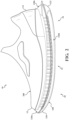
- an article of footwear 10 includes a sole structure 100 and an upper 200 attached to the sole structure 100.
- the article of footwear 10, and components thereof, may be described as including an anterior end 12 associated with a forward-most point of the footwear 10, and a posterior end 14 corresponding to a rearward-most point of the footwear 10.
- a longitudinal axis A 10 of the footwear 10 extends along a length of the footwear 10 from the anterior end 12 to the posterior end 14.
- the longitudinal axis A 10 generally divides the footwear 10 into a lateral side 16 and a medial side 18. Accordingly, the lateral side 16 and the medial side 18 respectively correspond with opposite sides of the footwear 10 and extend from the anterior end 12 to the posterior end 14.
- the article of footwear 10 may be divided into one or more regions along the longitudinal axis A 10 .
- the regions may include a forefoot region 20, a mid-foot region 22, and a heel region 24.
- the forefoot region 20 may correspond with toes and joints connecting metatarsal bones with phalanx bones of a foot.
- the mid-foot region 22 may correspond with an arch area of the foot, and the heel region 24 may correspond with rear regions of the foot, including a calcaneus bone.
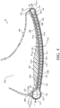
- the article of footwear 10, and more particularly, the sole structure 100 may be further described as including a peripheral region 26 and an interior region 28, as indicated by the dashed line in FIG. 4 .
- the peripheral region 26 is generally described as being a region between the interior region 28 and an outer perimeter of the sole structure 100. Particularly, the peripheral region 26 extends from the forefoot region 20 to the heel region 24 along each of the lateral side 16 and the medial side 18, and wraps around each of the forefoot region 20 and the heel region 24.
- the interior region 28 is circumscribed by the peripheral region 26, and extends from the forefoot region 20 to the heel region 24 along a central portion of the sole structure 100. Accordingly, each of the forefoot region 20, the mid-foot region 22, and the heel region 24 may be described as including the peripheral region 26 and the interior region 28.
- the sole structure 100 includes a midsole 102 configured to provide cushioning characteristics to the sole structure 100, and an outsole 104 configured to provide a ground-engaging surface of the article of footwear 10.
- the midsole 102 is formed compositely and includes multiple subcomponents.
- the midsole 102 includes a bladder 106 and an upper cushion 108 stacked upon the bladder 106.
- the midsole 102 may include a peripheral support member 110 surrounding an outer periphery of the bladder 106 and the upper cushion 108.
- the subcomponents 106, 108, 110 are assembled and secured to each other using various methods of bonding, including adhesively bonding and melding, for example.
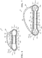
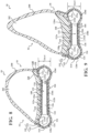
- the bladder 106 of the midsole 102 includes an opposing pair of barrier layers 112a, 112b, which can be joined to each other along a peripheral seam 114 to form a peripheral chamber 116 and an inner chamber 118.
- the barrier layers 112a, 112b include a first, upper barrier layer 112a and a second, lower barrier layer 112b.
- barrier layer encompasses both monolayer and multilayer films.
- one or both of the barrier layers 112a, 112b are each produced (e.g., thermoformed or blow molded) from a monolayer film (a single layer).
- one or both of the barrier layers 112a, 112b are each produced (e.g., thermoformed or blow molded) from a multilayer film (multiple sublayers).
- each layer or sublayer can have a film thickness ranging from about 0.2 micrometers to about be about 1 millimeter.
- the film thickness for each layer or sublayer can range from about 0.5 micrometers to about 500 micrometers.
- the film thickness for each layer or sublayer can range from about 1 micrometer to about 100 micrometers.
- barrier layers 112a, 112b can independently be transparent, translucent, and/or opaque.
- transparent for a barrier layer and/or a fluid-filled chamber means that light passes through the barrier layer in substantially straight lines and a viewer can see through the barrier layer. In comparison, for an opaque barrier layer, light does not pass through the barrier layer and one cannot see clearly through the barrier layer at all.
- a translucent barrier layer falls between a transparent barrier layer and an opaque barrier layer, in that light passes through a translucent layer but some of the light is scattered so that a viewer cannot see clearly through the layer.
- the barrier layers 112a, 112b can each be produced from an elastomeric material that includes one or more thermoplastic polymers and/or one or more cross-linkable polymers.
- the elastomeric material can include one or more thermoplastic elastomeric materials, such as one or more thermoplastic polyurethane (TPU) copolymers, one or more ethylene-vinyl alcohol (EVOH) copolymers, and the like.
- urethane groups can contain additional groups such as ester, ether, urea, allophanate, biuret, carbodiimide, oxazolidinyl, isocynaurate, uretdione, carbonate, and the like, in addition to urethane groups.
- suitable isocyanates for producing the polyurethane copolymer chains include diisocyanates, such as aromatic diisocyanates, aliphatic diisocyanates, and combinations thereof.
- suitable aromatic diisocyanates include toluene diisocyanate (TDI), TDI adducts with trimethyloylpropane (TMP), methylene diphenyl diisocyanate (MDI), xylene diisocyanate (XDI), tetramethylxylylene diisocyanate (TMXDI), hydrogenated xylene diisocyanate (HXDI), naphthalene 1,5-diisocyanate (NDI), 1,5-tetrahydronaphthalene diisocyanate, para-phenylene diisocyanate (PPDI), 3,3' - dimethyldiphenyl-4, 4' -diisocyanate (DDDI), 4,4 '-dibenzyl diisocyanate (
- the polyurethane polymer chains are produced from diisocynates including HMDI, TDI, MDI, H12 aliphatics, and combinations thereof.
- the thermoplastic TPU can include polyester-based TPU, polyether-based TPU, polycaprolactone-based TPU, polycarbonate-based TPU, polysiloxane-based TPU, or combinations thereof.
- the polymeric layer can be formed of one or more of the following: EVOH copolymers, poly(vinyl chloride), polyvinylidene polymers and copolymers (e.g., polyvinylidene chloride), polyamides (e.g., amorphous polyamides), amide-based copolymers, acrylonitrile polymers (e.g., acrylonitrile-methyl acrylate copolymers), polyethylene terephthalate, polyether imides, polyacrylic imides, and other polymeric materials known to have relatively low gas transmission rates. Blends of these materials as well as with the TPU copolymers described herein and optionally including combinations of polyimides and crystalline polymers, are also suitable.
- the barrier layers 112a, 112b may include two or more sublayers (multilayer film) such as shown in Mitchell et al., U.S. Patent No. 5,713,141 and Mitchell et al., U.S. Patent No. 5,952,065 .
- suitable multilayer films include microlayer films, such as those disclosed in Bonk et al., U.S. Patent No. 6,582,786 .
- barrier layers 112a, 112b may each independently include alternating sublayers of one or more TPU copolymer materials and one or more EVOH copolymer materials, where the total number of sublayers in each of barrier layers 112a, 112b includes at least four (4) sublayers, at least ten (10) sublayers, at least twenty (20) sublayers, at least forty (40) sublayers, and/or at least sixty (60) sublayers.
- the bladder 106 can be produced from barrier layers 112a, 112b using any suitable technique, such as thermoforming (e.g. vacuum thermoforming), blow molding, extrusion, injection molding, vacuum molding, rotary molding, transfer molding, pressure forming, heat sealing, casting, low-pressure casting, spin casting, reaction injection molding, radio frequency (RF) welding, and the like.
- barrier layers 112a, 112b can be produced by co-extrusion followed by vacuum thermoforming to produce an inflatable bladder 106, which can optionally include one or more valves (e.g., one way valves) that allows bladder 106 to be filled with the fluid (e.g., gas).
- the chambers 116, 118 of the bladder 106 can be provided in a fluid-filled (e.g., as provided in footwear 10) or in an unfilled state.
- the chambers 116, 118 can be filled to include any suitable fluid, such as a gas or liquid.
- the gas can include air, nitrogen (N 2 ), or any other suitable gas.
- the fluid provided to the chambers 116, 118 can result in the bladder 106 being pressurized.
- the fluid provided to the chambers 116, 118 can be at atmospheric pressure such that the bladder 106 is not pressurized but, rather, simply contains a volume of fluid at atmospheric pressure.
- the chambers 116, 118 can alternatively include other media, such as pellets, beads, ground recycled material, and the like (e.g., foamed beads and/or rubber beads).
- the barrier layers 112a, 112b desirably have a low gas transmission rate to preserve its retained gas pressure.
- the barrier layers 112a, 112b have a gas transmission rate for nitrogen gas that is at least about ten (10) times lower than a nitrogen gas transmission rate for a butyl rubber layer of substantially the same dimensions.
- the barrier layers 112a, 112b have a nitrogen gas transmission rate of 15 cubic-centimeter/square-meter•atmosphere•day (cm 3 /m 2 •atm•day) or less for an average film thickness of 500 micrometers (based on thicknesses of barrier layers 112a, 112b).
- the transmission rate is 10 cm 3 /m 2 •atm•day or less, 5 cm 3 /m 2 •atm•day or less, or 1 cm 3 /m 2 •atm•day or less.
- the upper barrier layer 112a and the lower barrier layer 112b cooperate to define a geometry (e.g., shape, thicknesses, width, and lengths) of the bladder 106.
- the barrier layers 112a, 112b may be joined together along the peripheral seam 114 to define an outer periphery of the bladder 106 and to seal the fluid (e.g., air) within the peripheral chamber 116 and the inner chamber 118.
- a length of the bladder 106 extends continuously from a first end 120 disposed at the anterior end 12 of the footwear 10 to a second end 122 disposed at the posterior end 14 of the footwear 10.
- the peripheral chamber 116 is formed in the peripheral region 26 of the bladder 106 and extends continuously and uninterrupted along the outer periphery of the bladder 106. As shown in FIGS. 5-11 , the barrier layers 112a, 112b are spaced apart from each other in the peripheral region 26 to define the peripheral chamber 116. Particularly, the interior surfaces of the barrier layers 112a, 112b are separated from each other such that the space between the barrier layers 112a defines an interior void 124 of the peripheral chamber 116, while a distance across exterior surfaces of the barrier layers 112a, 112b defines thicknesses T 116 of the peripheral chamber 116.
- the upper and lower barrier layers 112a cooperate to provide the peripheral chamber 116 with a tubular shape having a greater thickness T 116 than the inner chamber 118.
- the peripheral chamber 116 forms a bulbous or distended portion of the bladder 106 extending continuously and uninterrupted around the entire perimeter of the bladder 106.
- the peripheral chamber 116 is continuously formed around the perimeter of the bladder 106, the peripheral chamber 116 may be described as including a plurality of segments 128a-128d each corresponding with an end 120, 122 or side 16, 18 of the bladder 106.
- FIG. 4 shows that the peripheral chamber 116 includes an anterior segment 128a disposed at the first end 120 of the bladder 106, a posterior segment 128b disposed at the second end 122 of the bladder 106, a lateral side segment 128c extending continuously along the lateral side 16 of the bladder 106, and a medial side segment 128d extending continuously along the medial side 18 of the bladder 106.
- the anterior segment 128a extends along an arcuate path around the first end 120 of the bladder 106 from a first end 129a on the lateral side 16 of the bladder 106 to a second end 130a on the medial side 18 of the bladder 106.
- the anterior segment 128a defines a first thickness T 116-1 of the peripheral chamber 116 at the first end 120.
- the posterior segment 128b extends along an arcuate path around the second end 122 of the bladder 106 from a first end 129b disposed on the lateral side 16 to a second end 130b disposed on the medial side 18.
- the posterior segment 128b defines a second thickness T 116-2 of the peripheral chamber 116.
- the second thickness T 116-2 is greater than the first thickness T 116-1 such that the peripheral chamber 116 is thicker at the second end 122 than at the first end 120.
- a first one of the side segments 128c includes a lateral side segment 128c extending continuously along the lateral side from the first end 129a of the anterior segment 128a to the first end 129b of the posterior segment 128b.
- the thickness of the peripheral chamber 116 tapers continuously along each of the side segments 128c, 128d from the second thickness T 116-2 at the second end 122 to the first thickness T 116-1 at the first end 120.
- FIGS. 6-11 are taken in series along the length of the bladder 106 and illustrate the progressive increase in the thickness T 116 of the peripheral chamber 116 from the anterior segment 128a to the posterior segment 128b.
- FIG. 6 is a cross-sectional view taken across the bladder 106 where the side segments 128c, 128d connect to the ends 129a, 130a of the anterior segment 128a.
- each of the side segments 128c, 128d has the same thickness T 116-1 as the anterior segment 128a.
- FIGS. 7-10 are cross-sectional views taken along intermediate portions (i.e., between the anterior segment 128a and posterior segment 128b) of the bladder 106, as indicated in FIG. 4 .
- the intermediate portions of the side segments 128c, 128d include thicknesses T 116-3 ( FIG. 7 ), T 116-4 ( FIG. 8 ), T 116-5 ( FIG. 9 ), T 116-6 ( FIG. 10 ) that progressively and continuously increase along the length of the bladder 106 in a direction toward the heel region 24.
- FIG. 11 shows a cross-sectional view of the bladder 106 taken where the side segments 128c, 128d connect to the ends 129b, 130b of the posterior segment 128b. Accordingly, the side segments 128c, 128d have the same thickness T 116-2 as the posterior segment 128b.
- the barrier layers 112a, 112b cooperate to provide the peripheral chamber 116 with a tubular shape enclosing a fluid-filled interior void 124. As shown in FIGS. 6-11 , at least one of the upper barrier layer 112a and the lower barrier layer 112b may define one or more deformation zones 131a-131c along the peripheral chamber 116.
- the peripheral chamber 116 includes a first deformation zone 131a extending along an outer portion of the peripheral chamber 116 adjacent to the peripheral seam 114, a second deformation zone 131b extending along an inner portion of the peripheral chamber 116 adjacent to the inner chamber 118, and a third deformation zone 131c extending along an upper portion of the peripheral chamber 116 and connecting the first deformation zone 131a and the second deformation zone 131b.
- the portion of the upper barrier layer 112a forming the upper portion of the peripheral chamber 116 includes deformation zones 131a-131c formed as a plurality of connected sides of the peripheral chamber 116.
- at least a portion of the peripheral chamber 116 may have a polygonal shape defined by the deformation zones 131a-131c.
- the deformation zones 131a-131c may be progressively formed along a direction from the first end 120 of the bladder 106 to the second end 122 of the bladder 106.
- the deformation zones 131a-131c may have slight curvature and be substantially continuous in portions of the peripheral chamber 116 in the forefoot region ( FIGS. 6 and 7 ).
- the deformation zones 131a-131c may be substantially flat with clearly defined transitions in the portions of the peripheral chamber 116 in the heel region ( FIGS. 10 and 11 ).
- the deformation zones 131a-131c provide expansion regions along the peripheral chamber 116, such that when the bladder 106 is compressed and the pressure within the interior void 124 of the peripheral chamber 116 increases, the upper barrier layer 112a can progressively deform to accommodate or absorb the pressure increase.
- the progressive definition of the deformation zones 131a-131c along the lengths of the side segments 128c, 128d provides the heel region 24 with a greater degree of pressure compensation than the forefoot region 20 and mid-foot region 22 to accommodate forces associated with a heel strike.
- the inner chamber 118 of the bladder 106 is formed within the interior region 28 of the bladder 106, is continuously and completely surrounded by the peripheral chamber 116, and is in fluid communication with the peripheral chamber 116.
- the inner chamber 118 extends continuously along a length of the bladder 106 from the anterior segment 128a of the peripheral chamber 116 disposed at the first end 120 to the posterior segment 128b of the peripheral chamber disposed at the second end 122 of the bladder 106.
- the inner chamber 118 also extends continuously and uninterrupted between the lateral side segment 128c and the medial side segment 128d along the entire length of the inner chamber 118. Accordingly, the inner chamber 118 may be described as filling the entire space (i.e., the interior region 28) surrounded by the peripheral chamber 116.
- the upper tensile sheet 136a may be attached to the interior surface of the upper barrier layer 112a while the lower tensile sheet 136b may be attached to the interior surface of the lower barrier layer 112b. In this manner, when the inner chamber 118 receives a pressurized fluid, the tensile strands 134 of the tensile element 132 are placed in tension. Because the upper tensile sheet 136a is attached to the upper barrier layer 112a and the lower tensile sheet 136b is attached to the lower barrier layer 112b, the tensile strands 134 retain a desired shape of the inner chamber 118 when the pressurized fluid is injected into the interior void 126.
- the tensile element 132 provides the inner chamber 118 with a constant thickness T 118 extending along the length and width of the inner chamber 118.
- the thickness T 118 of the inner chamber 118 is less than the thicknesses T 116-1 -T 116-6 of the peripheral chamber 116.
- the portions of the upper and lower barrier layers 112a, 112b forming the inner chamber 118 are inwardly offset from portions the barrier layers 112a, 112 forming the peripheral chamber 116.
- the portions of the upper and lower barrier layers 112a, 112b forming the peripheral chamber 116 protrude from the portions of the upper and lower barrier layers 112a, 112b forming the inner chamber 118.
- the inner chamber 118 and the peripheral chamber 116 cooperate to define a pair of pockets or cavities 138a, 138b on opposite sides of the bladder 106.
- the bladder 106 includes an upper pocket 138a defined by the upper barrier layer 112a on a top side of the bladder 106 and a lower pocket 138b defined by the lower barrier layer 112b.
- a bottom surface of the upper pocket 138a is defined by the portion of the upper barrier layer 112a extending along the inner chamber 118 and an outer periphery of the upper pocket 138a is defined by the portion of the upper barrier layer 112a forming an inner portion (i.e., facing the interior region 28) of the peripheral chamber 116.
- a top surface of the lower pocket 138b is defined by the portion of the lower barrier layer 112b extending along the inner chamber 118 and an outer periphery of the lower pocket 138b is defined by the portion of the lower barrier layer 112b forming an inner portion (i.e., facing the interior region 28) of the peripheral chamber 116.
- the tensile element 132 may be configured to impart an overall shape or contour to the inner chamber 118. As shown in FIGS. 6-11 , the inner chamber 118 is substantially straight along the lateral direction from the lateral side 16 to the medial side 18. However, as shown in FIG. 5 , the inner chamber 118 may have an arcuate shape extending along the length of the bladder 106. Thus, although the thickness T 118 of the inner chamber 118 is substantially constant, the shape of the inner chamber 118 may curve from the first end 120 to the second end 122.
- the inner chamber 118 has an "upward" curvature along the longitudinal direction, such that the upper barrier layer 112a is concave and the lower barrier layer 112b is convex.
- a radius R 118 of curvature of the inner chamber 118 is substantially constant along the entire length of the inner chamber 118.
- the peripheral chamber 116 and the inner chamber 118 are integrally formed by the barrier layers 112a, 112b. Accordingly, the interior void 124 of the peripheral chamber 116 is in fluid communication with the interior void 126 of the inner chamber 118, such that the entire bladder 106 has a uniform pressure.
- the inner chamber 118 may be compressed between the ground surface and a plantar surface of the foot during an impact with the ground surface. When compressed, the pressure of the fluid within the bladder 106 increases and the fluid within the inner chamber 118 is displaced from the interior void 126 of the inner chamber 118 to the interior void 124 of the peripheral chamber 116.
- the portions of the barrier layers 112a, 112b forming the peripheral chamber 116 may include one or more deformation zones 131a-131c.
- the deformation zones 131a-131c of the peripheral chamber 116 are biased outwardly to accommodate the pressure change, thereby providing a damping effect along the peripheral region of the sole structure 100.
- the upper cushion 108 of the midsole is formed of a resilient polymeric material and is configured to be received within the upper pocket 138a of the bladder 106. As shown in FIGS. 3 and 5 , the upper cushion 108 extends continuously from a first end 140 disposed at the first end 120 of the bladder 106 to a second end 142 disposed at the second end 122 of the bladder 106.
- the upper cushion 108 further includes a top surface 144 defining a footbed of the sole structure 100 and a bottom surface 146 formed on an opposite side of the upper cushion 108 from the top surface 144. A distance between the top surface 144 and the bottom surface defines a thickness T 108 of the upper cushion 108.
- the upper cushion 108 further includes a peripheral side surface 148 extending from the top surface 144 to the bottom surface 146, which defines an outer peripheral profile of the upper cushion 108.
- the upper cushion 108 When the sole structure 100 is assembled, the upper cushion 108 is received within the upper pocket 138a such that the bottom surface 146 faces the inner chamber 118 and the peripheral side surface 148 mates with the peripheral chamber 116. As shown in FIGS. 5-11 , the peripheral side surface 148 may include a concave channel 150 configured to mate with the inner portion of the peripheral chamber 116. In some examples, the upper cushion 108 may be directly disposed within the upper pocket 138a, whereby the upper cushion 108 is attached directly to the inner chamber 118 and the peripheral chamber 116.
- the upper cushion 108 is configured as a sockliner or insole, and is disposed within an interior void 202 of the upper 200, such that a strobel 204 of the upper 200 is disposed between the bladder 106 and the upper cushion 108.
- the upper cushion 108 is formed of a resilient polymeric material, such as foam or rubber, to impart properties of cushioning, responsiveness, and energy distribution to the foot of the wearer.
- Example resilient polymeric materials may include those based on foaming or molding one or more polymers, such as one or more elastomers (e.g., thermoplastic elastomers (TPE)).
- the one or more polymers may include aliphatic polymers, aromatic polymers, or mixtures of both; and may include homopolymers, copolymers (including terpolymers), or mixtures of both.
- the one or more polymers may include olefinic homopolymers, olefinic copolymers, or blends thereof.
- olefinic polymers include polyethylene, polypropylene, and combinations thereof.
- the one or more polymers may include one or more ethylene copolymers, such as, ethylene-vinyl acetate (EVA) copolymers, EVOH copolymers, ethylene-ethyl acrylate copolymers, ethylene-unsaturated mono-fatty acid copolymers, and combinations thereof.
- EVA ethylene-vinyl acetate
- the one or more polymers may include one or more polyacrylates, such as polyacrylic acid, esters of polyacrylic acid, polyacrylonitrile, polyacrylic acetate, polymethyl acrylate, polyethyl acrylate, polybutyl acrylate, polymethyl methacrylate, and polyvinyl acetate; including derivatives thereof, copolymers thereof, and any combinations thereof.
- polyacrylates such as polyacrylic acid, esters of polyacrylic acid, polyacrylonitrile, polyacrylic acetate, polymethyl acrylate, polyethyl acrylate, polybutyl acrylate, polymethyl methacrylate, and polyvinyl acetate; including derivatives thereof, copolymers thereof, and any combinations thereof.
- the one or more polymers may include one or more ionomeric polymers.
- the ionomeric polymers may include polymers with carboxylic acid functional groups, sulfonic acid functional groups, salts thereof (e.g., sodium, magnesium, potassium, etc.), and/or anhydrides thereof.
- the ionomeric polymer(s) may include one or more fatty acid-modified ionomeric polymers, polystyrene sulfonate, ethylene-methacrylic acid copolymers, and combinations thereof.
- the one or more polymers may include one or more styrenic block copolymers, such as acrylonitrile butadiene styrene block copolymers, styrene acrylonitrile block copolymers, styrene ethylene butylene styrene block copolymers, styrene ethylene butadiene styrene block copolymers, styrene ethylene propylene styrene block copolymers, styrene butadiene styrene block copolymers, and combinations thereof.
- styrenic block copolymers such as acrylonitrile butadiene styrene block copolymers, styrene acrylonitrile block copolymers, styrene ethylene butylene styrene block copolymers, styrene ethylene butadiene styrene block
- the one or more polymers may include one or more polyamide copolymers (e.g., polyamide-polyether copolymers) and/or one or more polyurethanes (e.g., crosslinked polyurethanes and/or thermoplastic polyurethanes).
- suitable polyurethanes include those discussed above for barrier layers 112a, 112b.
- the one or more polymers may include one or more natural and/or synthetic rubbers, such as butadiene and isoprene.
- the foamed material may be foamed using a physical blowing agent which phase transitions to a gas based on a change in temperature and/or pressure, or a chemical blowing agent which forms a gas when heated above its activation temperature.
- the chemical blowing agent may be an azo compound such as azodicarbonamide, sodium bicarbonate, and/or an isocyanate.
- the foamed polymeric material may be a crosslinked foamed material.
- a peroxide-based crosslinking agent such as dicumyl peroxide may be used.
- the foamed polymeric material may include one or more fillers such as pigments, modified or natural clays, modified or unmodified synthetic clays, talc glass fiber, powdered glass, modified or natural silica, calcium carbonate, mica, paper, wood chips, and the like.
- the resilient polymeric material may be formed using a molding process.
- the uncured elastomer e.g., rubber
- a curing package such as a sulfur-based or peroxide-based curing package, calendared, formed into shape, placed in a mold, and vulcanized.
- the resilient polymeric material when the resilient polymeric material is a foamed material, the material may be foamed during a molding process, such as an injection molding process.
- a thermoplastic polymeric material may be melted in the barrel of an injection molding system and combined with a physical or chemical blowing agent and optionally a crosslinking agent, and then injected into a mold under conditions which activate the blowing agent, forming a molded foam.
- the foamed material when the resilient polymeric material is a foamed material, the foamed material may be a compression molded foam. Compression molding may be used to alter the physical properties (e.g., density, stiffness and/or durometer) of a foam, or to alter the physical appearance of the foam (e.g., to fuse two or more pieces of foam, to shape the foam, etc.), or both.
- Compression molding may be used to alter the physical properties (e.g., density, stiffness and/or durometer) of a foam, or to alter the physical appearance of the foam (e.g., to fuse two or more pieces of foam, to shape the foam, etc.), or both.
- the compression molding process desirably starts by forming one or more foam preforms, such as by injection molding and foaming a polymeric material, by forming foamed particles or beads, by cutting foamed sheet stock, and the like.
- the compression molded foam may then be made by placing the one or more preforms formed of foamed polymeric material(s) in a compression mold, and applying sufficient pressure to the one or more preforms to compress the one or more preforms in a closed mold.
- the mold is closed, sufficient heat and/or pressure is applied to the one or more preforms in the closed mold for a sufficient duration of time to alter the preform(s) by forming a skin on the outer surface of the compression molded foam, fuse individual foam particles to each other, permanently increase the density of the foam(s), or any combination thereof.
- the mold is opened and the molded foam article is removed from the mold.
- the midsole 102 further includes the peripheral support member 110 connecting the peripheral chamber 116 to the upper 200 along the entire periphery of the footwear 10.
- the peripheral support member 110 includes one or more of the elastomeric materials discussed above with respect to the barrier layers 112a, 112b. As shown in FIGS. 5-11 , the peripheral support member 110 includes a lower portion 152 attached to the outer portion (i.e., facing away from the interior region 28) of the peripheral chamber 116.
- the peripheral support member 110 also includes an upper portion 154 attached to the exterior of the upper 200.
- the peripheral support member 110 is configured to provide lateral stability between the upper 200 and the bladder 106 along the outer periphery of the footwear 10.
- the outsole 104 of the sole structure 100 may be formed as an over-molded component covering the entire lower barrier layer 112b of the bladder 106, thereby providing the sole structure 100 with an extra layer along the ground surface.
- the outsole 104 includes an inner surface 160 configured to attach to the lower barrier layer 112b of the bladder 106, and an outer surface 162 formed on an opposite side of the outsole 104 and configured to provide a ground-contacting surface of the sole structure 100.
- the outsole 104 also includes an interior portion 164 configured to mate with the lower pocket 138b of the bladder 106, and a peripheral channel 166 configured to receive the lower portion of the peripheral chamber 116.
- the upper 200 includes interior surfaces that define an interior void 202 configured to receive and secure a foot for support on the sole structure 100.
- the upper 200 may be formed from one or more materials that are stitched or adhesively bonded together to form the interior void 202. Suitable materials of the upper may include, but are not limited to, mesh, textiles, foam, leather, and synthetic leather. The materials may be selected and located to impart properties of durability, air-permeability, wear-resistance, flexibility, and comfort.
- the upper 200 includes the strobel 204 enclosing a bottom portion of the interior void 202. Stitching or adhesives may secure the strobel to the upper 200. As set forth above, the strobel 204 of the upper 200 may be disposed between the bladder 106 and the upper cushion 108 when the article of footwear 10 is assembled.
Landscapes
- Chemical & Material Sciences (AREA)
- Engineering & Computer Science (AREA)
- Materials Engineering (AREA)
- Footwear And Its Accessory, Manufacturing Method And Apparatuses (AREA)
Claims (15)
- Eine Blase (106) für einen Fußbekleidungsartikel (10), wobei die Blase (106) Folgendes umfasst:eine Innenkammer (118), die einen ersten inneren Hohlraum und ein Zugelement (132) beinhaltet, das innerhalb des ersten inneren Hohlraums angeordnet ist, wobei die Innenkammer (118) eine konstante Dicke (T118) aufweist, undeine Umfangskammer (116), die die Innenkammer (118) umgibt und einen zweiten inneren Hohlraum beinhaltet, wobei die Umfangskammer (116) eine variable Dicke aufweist, die größer ist als die konstante Dicke der Innenkammer (118).
- Die Blase (106) nach Anspruch 1, wobei die Umfangskammer (116) eine oder mehrere Verformungszonen (131a-131c) beinhaltet.
- Die Blase (106) nach Anspruch 2, wobei die Verformungszonen (131a-131c) im Wesentlichen gerade Seiten der Umfangskammer (116) beinhalten.
- Die Blase (106) nach Anspruch 2, wobei die Verformungszonen (131a-131c) entlang einer Länge der Blase (106) progressiv definiert sind.
- Die Blase (106) nach Anspruch 1, wobei die Umfangskammer (116) Folgendes beinhaltet: ein hinteres Segment (128b), das an einem ersten Ende (122) der Blase (106) angeordnet ist, und ein vorderes Segment (128a), das an einem zweiten Ende (120) der Blase (106) angeordnet ist, wobei das hintere Segment (128b) eine größere Dicke als das vordere Segment (128a) aufweist, insbesondere wobei die Umfangskammer (116) ein oder mehrere längliche Segmente (128c, 128d) beinhaltet, die das vordere Segment (128a) und das hintere Segment (128b) verbinden, wobei sich die variable Dicke der Blase (106) kontinuierlich vom hinteren Segment (128b) zum vorderen Segment (128a) verjüngt.
- Die Blase (106) nach irgendeinem der Ansprüche von 1 bis 5, die ferner eine erste Barriereschicht (112a) und eine zweite Barriereschicht (112b) umfasst, die zusammenwirken, um jeweils die Innenkammer (118) und die Umfangskammer (116) zu definieren, insbesondere wobei die erste Barriereschicht (112a) und die zweite Barriereschicht (112b) am Zugelement (132) in der Innenkammer (118) angebracht sind.
- Die Blase (106) nach irgendeinem der Ansprüche von 1 bis 6, wobei die Innenkammer (118) entlang einer Längsrichtung der Blase (106) gekrümmt ist, insbesondere wobei die Innenkammer (118) entlang einer Breitenrichtung der Blase (106) gerade ist.
- Eine Blase (106) für einen Fußbekleidungsartikel (10), wobei die Blase (106) Folgendes umfasst:eine Innenkammer (118) mit einer konstanten Dicke (T118); undeine Umfangskammer (116), die die Innenkammer (118) vollständig umgibt und mit dieser in Fluidverbindung steht, wobei die Umfangskammer (116) eine größere Dicke als die Innenkammer (118) aufweist und eine oder mehrere Verformungszonen (131a-131c) beinhaltet.
- Die Blase (106) nach Anspruch 8, wobei die eine oder die mehreren Verformungszonen (131a-131c) eine Vielzahl von Verformungszonen beinhalten, die sich entlang der Umfangskammer (116) erstrecken.
- Die Blase (106) nach irgendeinem der Ansprüche 8 bis 9, wobei die eine oder die mehreren Verformungszonen (131a-131c) durch im Wesentlichen gerade Seiten der Umfangskammer (116) definiert sind.
- Die Blase (106) nach irgendeinem der Ansprüche 8 bis 10, wobei die Verformungszonen (131a-131c) entlang einer Länge der Blase (106) progressiv definiert sind.
- Die Blase (106) nach irgendeinem der Ansprüche von 8 bis 11, wobei die Umfangskammer (116) Folgendes beinhaltet: ein hinteres Segment (128b), das an einem ersten Ende (122) der Blase (106) angeordnet ist, und ein vorderes Segment (128a), das an einem zweiten Ende (120) der Blase (106) angeordnet ist, wobei das hintere Segment (128b) eine größere Dicke als das vordere Segment (128a) aufweist, insbesondere wobei die Umfangskammer (116) ein oder mehrere längliche Segmente (128c, 128d) beinhaltet, die das vordere Segment (128a) und das hintere Segment (128b) verbinden, wobei sich die Dicke der Blase (106) kontinuierlich vom hinteren Segment (128b) zum vorderen Segment (128a) verjüngt.
- Die Blase (106) nach irgendeinem der Ansprüche von 8 bis 12, die ferner eine erste Barriereschicht (112a) und eine zweite Barriereschicht (112b) umfasst, die zusammenwirken, um jeweils die Innenkammer (118) und die Umfangskammer (116) zu definieren, insbesondere wobei die erste Barriereschicht (112a) und die zweite Barriereschicht (112b) an einem Zugelement (132) in der Innenkammer (118) angebracht sind.
- Die Blase (106) nach irgendeinem der Ansprüche von 8 bis 13, wobei die Innenkammer (118) entlang einer Längsrichtung der Blase gekrümmt ist.
- Die Blase (106) nach Anspruch 14, insbesondere wobei die Innenkammer (118) entlang einer Breitenrichtung der Blase (106) gerade ist.
Priority Applications (1)
| Application Number | Priority Date | Filing Date | Title |
|---|---|---|---|
| EP25167747.2A EP4552523A3 (de) | 2020-05-31 | 2021-05-26 | Sohlenstruktur für schuhwerk |
Applications Claiming Priority (2)
| Application Number | Priority Date | Filing Date | Title |
|---|---|---|---|
| US202063032670P | 2020-05-31 | 2020-05-31 | |
| PCT/US2021/034364 WO2021247337A1 (en) | 2020-05-31 | 2021-05-26 | Sole structure for article of footwear |
Related Child Applications (1)
| Application Number | Title | Priority Date | Filing Date |
|---|---|---|---|
| EP25167747.2A Division EP4552523A3 (de) | 2020-05-31 | 2021-05-26 | Sohlenstruktur für schuhwerk |
Publications (2)
| Publication Number | Publication Date |
|---|---|
| EP4157017A1 EP4157017A1 (de) | 2023-04-05 |
| EP4157017B1 true EP4157017B1 (de) | 2025-04-02 |
Family
ID=78707310
Family Applications (2)
| Application Number | Title | Priority Date | Filing Date |
|---|---|---|---|
| EP21733332.7A Active EP4157017B1 (de) | 2020-05-31 | 2021-05-26 | Sohlenstruktur für schuhwerk |
| EP25167747.2A Pending EP4552523A3 (de) | 2020-05-31 | 2021-05-26 | Sohlenstruktur für schuhwerk |
Family Applications After (1)
| Application Number | Title | Priority Date | Filing Date |
|---|---|---|---|
| EP25167747.2A Pending EP4552523A3 (de) | 2020-05-31 | 2021-05-26 | Sohlenstruktur für schuhwerk |
Country Status (4)
| Country | Link |
|---|---|
| US (1) | US12137769B2 (de) |
| EP (2) | EP4157017B1 (de) |
| CN (1) | CN115697124A (de) |
| WO (1) | WO2021247337A1 (de) |
Families Citing this family (3)
| Publication number | Priority date | Publication date | Assignee | Title |
|---|---|---|---|---|
| US12471669B2 (en) * | 2022-12-19 | 2025-11-18 | Nike, Inc. | Sole structure for article of footwear |
| TWI842631B (zh) * | 2023-09-22 | 2024-05-11 | 台灣百和工業股份有限公司 | 鞋底結構及鞋具 |
| US20250194743A1 (en) * | 2023-12-15 | 2025-06-19 | Nike, Inc. | Cushioning component for a wearable article and method of manufacturing same |
Family Cites Families (19)
| Publication number | Priority date | Publication date | Assignee | Title |
|---|---|---|---|---|
| US5245766A (en) * | 1990-03-30 | 1993-09-21 | Nike, Inc. | Improved cushioned shoe sole construction |
| US5595004A (en) * | 1994-03-30 | 1997-01-21 | Nike, Inc. | Shoe sole including a peripherally-disposed cushioning bladder |
| US5952065A (en) | 1994-08-31 | 1999-09-14 | Nike, Inc. | Cushioning device with improved flexible barrier membrane |
| CA2343816C (en) | 1998-09-11 | 2009-04-14 | Nike Innovate C.V. | Flexible membranes |
| US6571490B2 (en) * | 2000-03-16 | 2003-06-03 | Nike, Inc. | Bladder with multi-stage regionalized cushioning |
| US20070063368A1 (en) * | 2004-02-23 | 2007-03-22 | Nike, Inc. | Fluid-filled bladder incorporating a foam tensile member |
| US8015730B2 (en) * | 2007-01-08 | 2011-09-13 | Nike, Inc. | Footwear with vertically-arranged pump and pressure chambers |
| US8241451B2 (en) * | 2008-05-20 | 2012-08-14 | Nike, Inc. | Contoured fluid-filled chamber with a tensile member |
| US8789294B2 (en) * | 2011-03-16 | 2014-07-29 | Nike, Inc. | Contoured fluid-filled chamber with tensile structures |
| US8869430B2 (en) * | 2011-03-16 | 2014-10-28 | Nike, Inc. | Method of manufacturing a contoured fluid-filled chamber with tensile structures |
| US8839530B2 (en) * | 2011-04-12 | 2014-09-23 | Nike, Inc. | Method of lasting an article of footwear with a fluid-filled chamber |
| US9907357B2 (en) * | 2015-09-24 | 2018-03-06 | Nike, Inc. | Fluid-filled chamber for an article of footwear |
| JP6657388B2 (ja) * | 2015-09-24 | 2020-03-04 | ナイキ イノベイト シーブイ | コーティングされたキャリア内の粒子状発泡体 |
| US11026475B2 (en) * | 2016-09-08 | 2021-06-08 | Nike, Inc. | Flexible fluid-filled chamber with tensile member |
| US11304476B2 (en) * | 2016-12-01 | 2022-04-19 | The Board Of Regents Of The University Of Texas System | Variable stiffness apparatuses using an interconnected dual layer fluid-filled cell array |
| US10709199B2 (en) * | 2017-03-10 | 2020-07-14 | Nike, Inc. | Footwear sole structure having a fluid-filled chamber including a tensile member |
| EP4140350B1 (de) * | 2017-05-18 | 2025-09-17 | Nike Innovate C.V. | Polsterungsartikel mit zugkomponente und verfahren zur herstellung eines polsterungsartikels |
| US11109637B2 (en) * | 2017-08-31 | 2021-09-07 | Nike, Inc. | Cushioning arrangement for temperature control of a sole structure |
| EP3801109B1 (de) | 2018-05-30 | 2024-12-11 | NIKE Innovate C.V. | Schuhsohlenstruktur mit blase |
-
2021
- 2021-05-26 WO PCT/US2021/034364 patent/WO2021247337A1/en not_active Ceased
- 2021-05-26 EP EP21733332.7A patent/EP4157017B1/de active Active
- 2021-05-26 CN CN202180039060.2A patent/CN115697124A/zh active Pending
- 2021-05-26 EP EP25167747.2A patent/EP4552523A3/de active Pending
- 2021-05-26 US US17/331,249 patent/US12137769B2/en active Active
Also Published As
| Publication number | Publication date |
|---|---|
| US20210368923A1 (en) | 2021-12-02 |
| US12137769B2 (en) | 2024-11-12 |
| WO2021247337A1 (en) | 2021-12-09 |
| EP4552523A3 (de) | 2025-08-13 |
| EP4157017A1 (de) | 2023-04-05 |
| CN115697124A (zh) | 2023-02-03 |
| EP4552523A2 (de) | 2025-05-14 |
Similar Documents
| Publication | Publication Date | Title |
|---|---|---|
| US12161187B2 (en) | Airbag for article of footwear | |
| US12414604B2 (en) | Sole structure for article of footwear | |
| US12317952B2 (en) | Bladder and sole structure for article of footwear | |
| US20230218040A1 (en) | Airbag for article of footwear | |
| US20250248483A1 (en) | Sole structure for article of footwear | |
| US12064006B2 (en) | Airbag for article of footwear | |
| US11903442B2 (en) | Sole structure for article of footwear | |
| US20250185755A1 (en) | Sole structure for article of footwear | |
| US12245656B2 (en) | Sole structure for article of footwear | |
| US12471669B2 (en) | Sole structure for article of footwear | |
| EP4157017B1 (de) | Sohlenstruktur für schuhwerk | |
| US20250049175A1 (en) | Sole structure for article of footwear | |
| WO2025128809A1 (en) | Sole structure for article of footwear |
Legal Events
| Date | Code | Title | Description |
|---|---|---|---|
| STAA | Information on the status of an ep patent application or granted ep patent |
Free format text: STATUS: UNKNOWN |
|
| STAA | Information on the status of an ep patent application or granted ep patent |
Free format text: STATUS: THE INTERNATIONAL PUBLICATION HAS BEEN MADE |
|
| PUAI | Public reference made under article 153(3) epc to a published international application that has entered the european phase |
Free format text: ORIGINAL CODE: 0009012 |
|
| STAA | Information on the status of an ep patent application or granted ep patent |
Free format text: STATUS: REQUEST FOR EXAMINATION WAS MADE |
|
| 17P | Request for examination filed |
Effective date: 20221117 |
|
| AK | Designated contracting states |
Kind code of ref document: A1 Designated state(s): AL AT BE BG CH CY CZ DE DK EE ES FI FR GB GR HR HU IE IS IT LI LT LU LV MC MK MT NL NO PL PT RO RS SE SI SK SM TR |
|
| P01 | Opt-out of the competence of the unified patent court (upc) registered |
Effective date: 20230515 |
|
| DAV | Request for validation of the european patent (deleted) | ||
| DAX | Request for extension of the european patent (deleted) | ||
| REG | Reference to a national code |
Ref country code: DE Ref legal event code: R079 Ipc: A43B0013120000 Ref country code: DE Ref legal event code: R079 Ref document number: 602021028525 Country of ref document: DE Free format text: PREVIOUS MAIN CLASS: A43B0013180000 Ipc: A43B0013120000 |
|
| GRAP | Despatch of communication of intention to grant a patent |
Free format text: ORIGINAL CODE: EPIDOSNIGR1 |
|
| STAA | Information on the status of an ep patent application or granted ep patent |
Free format text: STATUS: GRANT OF PATENT IS INTENDED |
|
| RIC1 | Information provided on ipc code assigned before grant |
Ipc: A43B 13/20 20060101ALI20241014BHEP Ipc: A43B 13/18 20060101ALI20241014BHEP Ipc: A43B 13/12 20060101AFI20241014BHEP |
|
| INTG | Intention to grant announced |
Effective date: 20241023 |
|
| GRAS | Grant fee paid |
Free format text: ORIGINAL CODE: EPIDOSNIGR3 |
|
| GRAA | (expected) grant |
Free format text: ORIGINAL CODE: 0009210 |
|
| STAA | Information on the status of an ep patent application or granted ep patent |
Free format text: STATUS: THE PATENT HAS BEEN GRANTED |
|
| AK | Designated contracting states |
Kind code of ref document: B1 Designated state(s): AL AT BE BG CH CY CZ DE DK EE ES FI FR GB GR HR HU IE IS IT LI LT LU LV MC MK MT NL NO PL PT RO RS SE SI SK SM TR |
|
| REG | Reference to a national code |
Ref country code: GB Ref legal event code: FG4D |
|
| REG | Reference to a national code |
Ref country code: CH Ref legal event code: EP |
|
| REG | Reference to a national code |
Ref country code: IE Ref legal event code: FG4D |
|
| REG | Reference to a national code |
Ref country code: DE Ref legal event code: R096 Ref document number: 602021028525 Country of ref document: DE |
|
| PGFP | Annual fee paid to national office [announced via postgrant information from national office to epo] |
Ref country code: DE Payment date: 20250408 Year of fee payment: 5 |
|
| PGFP | Annual fee paid to national office [announced via postgrant information from national office to epo] |
Ref country code: FR Payment date: 20250409 Year of fee payment: 5 |
|
| PGFP | Annual fee paid to national office [announced via postgrant information from national office to epo] |
Ref country code: AT Payment date: 20250721 Year of fee payment: 5 |
|
| REG | Reference to a national code |
Ref country code: NL Ref legal event code: MP Effective date: 20250402 |
|
| PG25 | Lapsed in a contracting state [announced via postgrant information from national office to epo] |
Ref country code: NL Free format text: LAPSE BECAUSE OF FAILURE TO SUBMIT A TRANSLATION OF THE DESCRIPTION OR TO PAY THE FEE WITHIN THE PRESCRIBED TIME-LIMIT Effective date: 20250402 |
|
| REG | Reference to a national code |
Ref country code: AT Ref legal event code: MK05 Ref document number: 1780397 Country of ref document: AT Kind code of ref document: T Effective date: 20250402 |
|
| PG25 | Lapsed in a contracting state [announced via postgrant information from national office to epo] |
Ref country code: FI Free format text: LAPSE BECAUSE OF FAILURE TO SUBMIT A TRANSLATION OF THE DESCRIPTION OR TO PAY THE FEE WITHIN THE PRESCRIBED TIME-LIMIT Effective date: 20250402 Ref country code: ES Free format text: LAPSE BECAUSE OF FAILURE TO SUBMIT A TRANSLATION OF THE DESCRIPTION OR TO PAY THE FEE WITHIN THE PRESCRIBED TIME-LIMIT Effective date: 20250402 Ref country code: PT Free format text: LAPSE BECAUSE OF FAILURE TO SUBMIT A TRANSLATION OF THE DESCRIPTION OR TO PAY THE FEE WITHIN THE PRESCRIBED TIME-LIMIT Effective date: 20250804 |
|
| REG | Reference to a national code |
Ref country code: LT Ref legal event code: MG9D |
|
| PG25 | Lapsed in a contracting state [announced via postgrant information from national office to epo] |
Ref country code: NO Free format text: LAPSE BECAUSE OF FAILURE TO SUBMIT A TRANSLATION OF THE DESCRIPTION OR TO PAY THE FEE WITHIN THE PRESCRIBED TIME-LIMIT Effective date: 20250702 Ref country code: GR Free format text: LAPSE BECAUSE OF FAILURE TO SUBMIT A TRANSLATION OF THE DESCRIPTION OR TO PAY THE FEE WITHIN THE PRESCRIBED TIME-LIMIT Effective date: 20250703 |
|
| PG25 | Lapsed in a contracting state [announced via postgrant information from national office to epo] |
Ref country code: PL Free format text: LAPSE BECAUSE OF FAILURE TO SUBMIT A TRANSLATION OF THE DESCRIPTION OR TO PAY THE FEE WITHIN THE PRESCRIBED TIME-LIMIT Effective date: 20250402 |
|
| PG25 | Lapsed in a contracting state [announced via postgrant information from national office to epo] |
Ref country code: BG Free format text: LAPSE BECAUSE OF FAILURE TO SUBMIT A TRANSLATION OF THE DESCRIPTION OR TO PAY THE FEE WITHIN THE PRESCRIBED TIME-LIMIT Effective date: 20250402 |
|
| PG25 | Lapsed in a contracting state [announced via postgrant information from national office to epo] |
Ref country code: HR Free format text: LAPSE BECAUSE OF FAILURE TO SUBMIT A TRANSLATION OF THE DESCRIPTION OR TO PAY THE FEE WITHIN THE PRESCRIBED TIME-LIMIT Effective date: 20250402 |
|
| PG25 | Lapsed in a contracting state [announced via postgrant information from national office to epo] |
Ref country code: AT Free format text: LAPSE BECAUSE OF FAILURE TO SUBMIT A TRANSLATION OF THE DESCRIPTION OR TO PAY THE FEE WITHIN THE PRESCRIBED TIME-LIMIT Effective date: 20250402 |
|
| PG25 | Lapsed in a contracting state [announced via postgrant information from national office to epo] |
Ref country code: RS Free format text: LAPSE BECAUSE OF FAILURE TO SUBMIT A TRANSLATION OF THE DESCRIPTION OR TO PAY THE FEE WITHIN THE PRESCRIBED TIME-LIMIT Effective date: 20250702 |
|
| PG25 | Lapsed in a contracting state [announced via postgrant information from national office to epo] |
Ref country code: IS Free format text: LAPSE BECAUSE OF FAILURE TO SUBMIT A TRANSLATION OF THE DESCRIPTION OR TO PAY THE FEE WITHIN THE PRESCRIBED TIME-LIMIT Effective date: 20250802 |
|
| PG25 | Lapsed in a contracting state [announced via postgrant information from national office to epo] |
Ref country code: LV Free format text: LAPSE BECAUSE OF FAILURE TO SUBMIT A TRANSLATION OF THE DESCRIPTION OR TO PAY THE FEE WITHIN THE PRESCRIBED TIME-LIMIT Effective date: 20250402 |
|
| REG | Reference to a national code |
Ref country code: CH Ref legal event code: H13 Free format text: ST27 STATUS EVENT CODE: U-0-0-H10-H13 (AS PROVIDED BY THE NATIONAL OFFICE) Effective date: 20251223 |
|
| REG | Reference to a national code |
Ref country code: DE Ref legal event code: R097 Ref document number: 602021028525 Country of ref document: DE |
|
| PG25 | Lapsed in a contracting state [announced via postgrant information from national office to epo] |
Ref country code: DK Free format text: LAPSE BECAUSE OF FAILURE TO SUBMIT A TRANSLATION OF THE DESCRIPTION OR TO PAY THE FEE WITHIN THE PRESCRIBED TIME-LIMIT Effective date: 20250402 Ref country code: SM Free format text: LAPSE BECAUSE OF FAILURE TO SUBMIT A TRANSLATION OF THE DESCRIPTION OR TO PAY THE FEE WITHIN THE PRESCRIBED TIME-LIMIT Effective date: 20250402 |
|
| PG25 | Lapsed in a contracting state [announced via postgrant information from national office to epo] |
Ref country code: LU Free format text: LAPSE BECAUSE OF NON-PAYMENT OF DUE FEES Effective date: 20250526 |
|
| PG25 | Lapsed in a contracting state [announced via postgrant information from national office to epo] |
Ref country code: CH Free format text: LAPSE BECAUSE OF NON-PAYMENT OF DUE FEES Effective date: 20250531 |
|
| PG25 | Lapsed in a contracting state [announced via postgrant information from national office to epo] |
Ref country code: CZ Free format text: LAPSE BECAUSE OF FAILURE TO SUBMIT A TRANSLATION OF THE DESCRIPTION OR TO PAY THE FEE WITHIN THE PRESCRIBED TIME-LIMIT Effective date: 20250402 |
|
| PG25 | Lapsed in a contracting state [announced via postgrant information from national office to epo] |
Ref country code: EE Free format text: LAPSE BECAUSE OF FAILURE TO SUBMIT A TRANSLATION OF THE DESCRIPTION OR TO PAY THE FEE WITHIN THE PRESCRIBED TIME-LIMIT Effective date: 20250402 |
|
| PG25 | Lapsed in a contracting state [announced via postgrant information from national office to epo] |
Ref country code: SK Free format text: LAPSE BECAUSE OF FAILURE TO SUBMIT A TRANSLATION OF THE DESCRIPTION OR TO PAY THE FEE WITHIN THE PRESCRIBED TIME-LIMIT Effective date: 20250402 |
|
| PG25 | Lapsed in a contracting state [announced via postgrant information from national office to epo] |
Ref country code: IT Free format text: LAPSE BECAUSE OF FAILURE TO SUBMIT A TRANSLATION OF THE DESCRIPTION OR TO PAY THE FEE WITHIN THE PRESCRIBED TIME-LIMIT Effective date: 20250402 |
|
| REG | Reference to a national code |
Ref country code: BE Ref legal event code: MM Effective date: 20250531 |
|
| PG25 | Lapsed in a contracting state [announced via postgrant information from national office to epo] |
Ref country code: MC Free format text: LAPSE BECAUSE OF FAILURE TO SUBMIT A TRANSLATION OF THE DESCRIPTION OR TO PAY THE FEE WITHIN THE PRESCRIBED TIME-LIMIT Effective date: 20250402 |
|
| PLBE | No opposition filed within time limit |
Free format text: ORIGINAL CODE: 0009261 |
|
| STAA | Information on the status of an ep patent application or granted ep patent |
Free format text: STATUS: NO OPPOSITION FILED WITHIN TIME LIMIT |
|
| PG25 | Lapsed in a contracting state [announced via postgrant information from national office to epo] |
Ref country code: RO Free format text: LAPSE BECAUSE OF FAILURE TO SUBMIT A TRANSLATION OF THE DESCRIPTION OR TO PAY THE FEE WITHIN THE PRESCRIBED TIME-LIMIT Effective date: 20250402 |
|
| REG | Reference to a national code |
Ref country code: CH Ref legal event code: L10 Free format text: ST27 STATUS EVENT CODE: U-0-0-L10-L00 (AS PROVIDED BY THE NATIONAL OFFICE) Effective date: 20260211 |
|
| 26N | No opposition filed |
Effective date: 20260105 |
|
| PGFP | Annual fee paid to national office [announced via postgrant information from national office to epo] |
Ref country code: GB Payment date: 20260316 Year of fee payment: 6 |
|
| PG25 | Lapsed in a contracting state [announced via postgrant information from national office to epo] |
Ref country code: IE Free format text: LAPSE BECAUSE OF NON-PAYMENT OF DUE FEES Effective date: 20250526 |
|
| PG25 | Lapsed in a contracting state [announced via postgrant information from national office to epo] |
Ref country code: BE Free format text: LAPSE BECAUSE OF NON-PAYMENT OF DUE FEES Effective date: 20250531 |