EP4156942B1 - Cutting apparatus for dough products - Google Patents
Cutting apparatus for dough products Download PDFInfo
- Publication number
- EP4156942B1 EP4156942B1 EP21735072.7A EP21735072A EP4156942B1 EP 4156942 B1 EP4156942 B1 EP 4156942B1 EP 21735072 A EP21735072 A EP 21735072A EP 4156942 B1 EP4156942 B1 EP 4156942B1
- Authority
- EP
- European Patent Office
- Prior art keywords
- cutting
- cutting elements
- shoulder
- sidewall
- angle
- Prior art date
- Legal status (The legal status is an assumption and is not a legal conclusion. Google has not performed a legal analysis and makes no representation as to the accuracy of the status listed.)
- Active
Links
Images


Classifications
-
- B—PERFORMING OPERATIONS; TRANSPORTING
- B26—HAND CUTTING TOOLS; CUTTING; SEVERING
- B26D—CUTTING; DETAILS COMMON TO MACHINES FOR PERFORATING, PUNCHING, CUTTING-OUT, STAMPING-OUT OR SEVERING
- B26D1/00—Cutting through work characterised by the nature or movement of the cutting member or particular materials not otherwise provided for; Apparatus or machines therefor; Cutting members therefor
- B26D1/56—Cutting through work characterised by the nature or movement of the cutting member or particular materials not otherwise provided for; Apparatus or machines therefor; Cutting members therefor involving a cutting member which travels with the work otherwise than in the direction of the cut, i.e. flying cutter
- B26D1/62—Cutting through work characterised by the nature or movement of the cutting member or particular materials not otherwise provided for; Apparatus or machines therefor; Cutting members therefor involving a cutting member which travels with the work otherwise than in the direction of the cut, i.e. flying cutter and is rotating about an axis parallel to the line of cut, e.g. mounted on a rotary cylinder
- B26D1/626—Cutting through work characterised by the nature or movement of the cutting member or particular materials not otherwise provided for; Apparatus or machines therefor; Cutting members therefor involving a cutting member which travels with the work otherwise than in the direction of the cut, i.e. flying cutter and is rotating about an axis parallel to the line of cut, e.g. mounted on a rotary cylinder for thin material, e.g. for sheets, strips or the like
-
- A—HUMAN NECESSITIES
- A21—BAKING; EDIBLE DOUGHS
- A21C—MACHINES OR EQUIPMENT FOR MAKING OR PROCESSING DOUGHS; HANDLING BAKED ARTICLES MADE FROM DOUGH
- A21C11/00—Other machines for forming the dough into its final shape before cooking or baking
- A21C11/02—Embossing machines
- A21C11/04—Embossing machines with cutting and embossing rollers or drums
-
- B—PERFORMING OPERATIONS; TRANSPORTING
- B26—HAND CUTTING TOOLS; CUTTING; SEVERING
- B26D—CUTTING; DETAILS COMMON TO MACHINES FOR PERFORATING, PUNCHING, CUTTING-OUT, STAMPING-OUT OR SEVERING
- B26D2210/00—Machines or methods used for cutting special materials
- B26D2210/02—Machines or methods used for cutting special materials for cutting food products, e.g. food slicers
-
- Y—GENERAL TAGGING OF NEW TECHNOLOGICAL DEVELOPMENTS; GENERAL TAGGING OF CROSS-SECTIONAL TECHNOLOGIES SPANNING OVER SEVERAL SECTIONS OF THE IPC; TECHNICAL SUBJECTS COVERED BY FORMER USPC CROSS-REFERENCE ART COLLECTIONS [XRACs] AND DIGESTS
- Y10—TECHNICAL SUBJECTS COVERED BY FORMER USPC
- Y10S—TECHNICAL SUBJECTS COVERED BY FORMER USPC CROSS-REFERENCE ART COLLECTIONS [XRACs] AND DIGESTS
- Y10S83/00—Cutting
- Y10S83/929—Particular nature of work or product
- Y10S83/932—Edible
-
- Y—GENERAL TAGGING OF NEW TECHNOLOGICAL DEVELOPMENTS; GENERAL TAGGING OF CROSS-SECTIONAL TECHNOLOGIES SPANNING OVER SEVERAL SECTIONS OF THE IPC; TECHNICAL SUBJECTS COVERED BY FORMER USPC CROSS-REFERENCE ART COLLECTIONS [XRACs] AND DIGESTS
- Y10—TECHNICAL SUBJECTS COVERED BY FORMER USPC
- Y10T—TECHNICAL SUBJECTS COVERED BY FORMER US CLASSIFICATION
- Y10T83/00—Cutting
- Y10T83/929—Tool or tool with support
- Y10T83/9372—Rotatable type
- Y10T83/9408—Spaced cut forming tool
Definitions
- the present disclosure describes an cutting apparatus suitable to create a plurality of uniformly shaped dough products.
- the patterned sheet is then stripped from the front roller (e.g. with a wire), with the product pieces falling down onto a conveyor belt, and with the surrounding web of "rework" dough, if any, returning to the hopper above the two sheeter rollers to be recombined fresh dough or directing the rework to waste.
- front roller e.g. with a wire
- EP0541834A1 discloses a specially shaped pizza plate in which a sheet of dough is cut out by a punch action to produce the base of the pizza.
- DE202015104796U1 discloses a dough processing machine for the production of pasta in which continuous dough blanks can be continuously punched out of a dough path by the rotation of a drum.
- the cutting device of this machine comprises a cutting surface containing a plurality of cutting elements, each cutting element comprising: a cutting edge at the top; an interior sidewall extending from a base to the top with an interior sidewall angle; an exterior sidewall extending from the base to the top with an exterior sidewall angle;wherein a portion of the exterior sidewall of one of the plurality of cutting elements touches a portion of the exterior sidewall of an adjacent one of the plurality of cutting elements.
- FR2406390A1 discloses a shaper and cutter for biscuit dough comprising a polyamide block with a recess of the desired biscuit shape.
- the invention is defined in claim 1.
- the interior sidewall angle is greater than the exterior sidewall angle by about 5° or more. In some instances, the interior sidewall angle is at least 20° or more. Alternatively or additionally, the exterior sidewall angle is about 20° or less.
- the interior sidewall angle ranges from about 15° to about 35°.
- the exterior sidewall angle is about 5° to about 15°.
- a shoulder is provided on the interior sidewall between the base of the cutting element and the top of the cutting element.
- the shoulder has a base and a sidewall that extends from the shoulder base to the top of the cutting element at a shoulder sidewall angle.
- the interior sidewall angle is greater than the shoulder sidewall angle by about 5° degrees or more. In some instances, the interior sidewall angle is at least 20° or more. Alternatively or additionally, the shoulder sidewall angle is about 20° or less.
- the shoulder base has a width that is greater than a width of the top flat surface and in some instances, the width of the shoulder is about 1.5 times or greater than the width of the top flat surface.
- the shoulder has a height measured from a shoulder base to the top flat surface that is less than a height of the top flat surface measured from the top flat surface to the cutting surface. In these instances, the shoulder height may be between about 20% to about 40% of the height of the top surface.
- exterior sidewall and shoulder sidewall define a cutting angle such that the cutting angle is less than the interior side wall angle and, in some instances is about 5° less.
- the cutting element may have any suitable shape such as a parallelogram, circle, oval, ellipse, or a complex geometrical shape.
- the at least one cutting element is an ellipse and, it is contemplated that all the cutting elements are elliptical. In those instances, where the cutting element is elliptical, each ellipse has a major axis that is between about 1.5 to about 2.0 times longer than a minor axis.
- the size of the cutting elements may be the same or different and in one embodiment, all the cutting elements have a size that is equal.
- the apparatus includes a plurality of cutting elements, the cutting elements are arranged such that a portion of the exterior sidewall of one of the plurality of cutting elements touches a portion of the exterior sidewall of an adjacent one of the plurality of cutting elements.
- the cutting elements may be arranged such that a portion of the exterior sidewall of one of the plurality of cutting elements touches a portion of the exterior sidewall of at least four adjacent one of the plurality of cutting elements.
- the cutting elements may be arranged such that a portion of the exterior sidewall of one of the plurality of cutting elements touches a portion of the exterior sidewall of six adjacent one of the plurality of cutting elements.
- the cutting elements By controlling the geometry of the cutting elements and the pattern of the cutting elements on the cutting surface, it has been found that the amount of waste can be reduced while efficiently cutting the dough to provide a plurality of similarly shaped foodstuffs.
- the cutting elements may be arranged in alternating rows such that the ends of the major axis of each cutting element in one row are approximately at the center point of the cutting elements in the adjacent row.
- a gap is created that has a generally triangular shape with curvilinear sides.
- the volume of the gap is at least 30 times less than the volume of each cutting element.
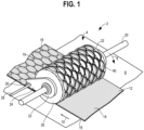
- a product assembly line 2 incorporating a cutting apparatus 4 is depicted.
- the product assembly 2 line has a sheet of dough 12 with a first surface 14 and a second surface 16 traveling from right to left upon a conveyor 8 that is moving in the direction shown by arrow 10.
- the dough is formed in a batch maker or the like and transferred to the product assembly line 2 where it is processed into a dough sheet 12.
- the sheet of dough 12 is delivered by conveyor 8 to the cutting apparatus 4.
- the cutting apparatus 4 rotates in the direction indicated by the arrow 6.
- the cutting apparatus 4 includes a plurality, of cutting patterns, molds, or elements 40 disposed on an exterior or cutting surface 32 of a cylindrical, rotatably driven drum 30 for forming and cutting the dough sheet 12 into a desired number of uniform shaped pieces 18.
- the plurality of cutting elements 40 are mounted relative to the conveyor 8 such that, when the dough sheet 12 is traveling in the feed direction 10, the cutting elements 40 engage the dough sheet 12 to cut and sever the dough to provide a plurality of cuts in the dough sheet, resulting in the formation of individual dough pieces or products 18 and intermediate, recyclable dough pieces 19.
- the drum 30 can be positively driven or driven by the frictional engagement between the cutting elements 40 and the dough sheet 12 or the conveyor 8. In operation, the cutting elements 40 extend all the way through the dough sheet 12 to lightly engage the conveyor 8 and completely sever the dough sheet 12.
- the dough sheet 12 can have any suitable thickness, with, of course, a corresponding change in the size (height or depth) of the cutting elements 40, in order to form products 18 of varying depth or thickness.
- the post processing station can include, for example, proofing, baking, freezing and/or packaging.
- the cutting elements 40 are provided on a surface of a pressing element instead of a rotating drum such that the pressing element intermittently contacts a portion of a dough sheet to cut the dough sheet into a desired number of uniform shaped pieces.
- the rotating drum 30 may be mounted on a drive shaft 20.
- Side plates 22 (only one of which is shown) may be mounted on either side of the rotating drum 30.
- the side plates 22 may each include an elongated side end portion 24, respectively, that extend in the direction of travel 10 of the dough sheet.
- Each elongated side end portions 24 includes a notch 26 to receive a pivot shaft 28 that extends parallel to the drive shaft 20.
- the pivot shaft 28 allows the rotating drum 30 and the drive shaft 20 to pivot and lift up off of the dough sheet 12 when desired, such as at the end of a production cycle.
- a dough roller (not shown) may be freely rotatably mounted on the pivot shaft 28.
- a plurality of the cutting elements 40 are disposed on the exterior of the rotating drum 30 to define a cutting surface 32.
- the cutting elements 40 may be disposed or provided on the exterior surface in any suitable manner.
- the various cutting elements 40 are provided as part of a sleeve that extends about exterior surface and is secured for rotation with the drum 30.
- the cutting elements 40 may be provided directly on exterior surface by any suitable means depending on the material forming the cutting elements.
- the cutting elements 40 may be provided by engraving, laser etching, or the like.
- various suitable materials could be used for the cutting elements 40 such as metals, plastics, coated metals, and the like.
- the cutting elements could be formed from a metal such as stainless steel coated with polytetrafluoroethylene.
- a plan view of a portion of the cutting pattern or cutting surface 32 provided on the rotating drum 30 to form the cutting apparatus 4 is shown. It will be appreciated that the cutting pattern or cutting surface 32 has dimensions suitable to completely cover or encircle the drum 30. It will be appreciated that the cutting surface 32 contains a plurality of cutting elements 40 each of which have the same or substantially the same shape.
- Each cutting element 40 may have any suitable shape such as a parallelogram, circle, oval, ellipse, or a complex geometrical shape generally defined by its exterior sidewall 50 (shown in Fig. 4 ).
- the cutting elements 40 are elliptical and, it is contemplated that all the cutting elements 40 are elliptical.
- each ellipse has a major axis 42 and a minor axis 44 such that their intersection defines the center or center point 46.
- the length of the major axis 42 is from about 10 mm to about 50 mm or about 15 mm to about 40 mm, or about 20 mm to about 30 mm and may be about 20 mm to about 25 mm of about 23 mm.
- the length of the minor axis is from about 2 mm to about 25 mm, or about 5 mm to about 20 mm, or about 9 mm to about 15 mm, or about 13 mm.
- the major axis is about 1.5 to about 2.0 times longer than the length of the minor axis 44.
- the lengths of the major axis 42 and the minor axis 44 are measured as the distance from each of the respective exterior side walls 50.
- the cutting elements 40 may be arranged in alternating rows such that the ends of the major axis 42 of each cutting element 40 in one row are approximately at the center point 46 of the cutting elements 40 in the adjacent row. It will also be appreciated that the plurality of cutting elements 40 are arranged such that a portion of the exterior sidewall 50 of one of the plurality of cutting elements 40 touches a portion of the exterior sidewall 50 of an adjacent one of the plurality of cutting elements 40. In other embodiments, the cutting elements 40 may be arranged such that a portion of the exterior sidewall 50 of one of the plurality of cutting elements 40 touches a portion of the exterior sidewall 50 of at least four adjacent one of the plurality of cutting elements 40. In yet other embodiments, the cutting elements 40 may be arranged such that a portion of the exterior sidewall 50 of one of the plurality of cutting elements 40 touches a portion of the exterior sidewall 40 of six adjacent one of the plurality of cutting elements 40.
- interstitial gaps 90 are created.
- the interstitial gaps 90 are generally triangular shaped with curvilinear (concave) sides.
- the volume of the interstitial gap 90 is at least 30 times less than the volume of each cutting element 40.
- two of the sides 94a, 94b may have generally the same length and one of the sides 92 may be longer than the other two sides.
- the two sides 94a, 94b which are shorter, may have a length from about 1 mm to about 6 mm, or about 2 mm to about 5 mm, or about 3 mm.
- the long side 92 may have a length from about 2 mm to about 8 mm, or about 3 mm to about 6 mm, or about 4 mm.
- each cutting element 40 may be spaced from adjacent cutting elements 40. In other words, in this instance, each cutting element 40 does not touch another cutting element 40 and there is a gap between each adjacent cutting element 40.
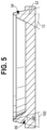
- Each cutting element 40 has a top 60 that has a flat surface 62 with a width 64.
- the width 64 of the top refers 62 to the width at the top of the cutting element 40 (and may be considered the thickness of the cutting element).
- the width 64 of the top ranges from about 0.2 to about 0.6 mm, or about 0.3 mm to about 0.5 mm, or about 0.4 mm.
- the top surface 62 is at a cutting element height or cutting depth 66, which is the distance between the top surface 62 and the top of the cutting surface 34.
- the cutting element height of cutting depth 66 may differ depending on the thickness of the dough. In one instance, when the dough has a thickness of approximately 1.8 mm to about 2.4 mm, the element height (or cutting depth) 66 may be in the range of about 3.0 mm to about 4.0 mm, or about 3.5 mm.
- Each cutting element 40 has an interior sidewall 70 and an exterior sidewall 50.
- the interior sidewall 70 extends from the top of the cutting surface 34 toward the top surface 62 at an interior sidewall angle 72.
- the exterior sidewall 50 extends from the top of the cutting surface 34 to the top surface 62 at an exterior sidewall angle 52.
- the interior 72 and exterior 52 sidewall angles refer to the angle of the sidewalls with respect to an imaginary line 54 that is normal to the top of the cutting surface 34.
- the interior sidewall angle 72 is also referred to as a release angle which is relevant to the cutting of dough. It is desirable that the interior sidewall angle 72 be larger than both the exterior sidewall angle 52 and the cutting angle, which will be defined in more detail below so that the cutting elements 40 release from the dough after cutting the dough.
- the interior sidewall angle 72 is greater than the exterior sidewall angle 52.
- the interior sidewall angle 72 can be greater than the exterior sidewall angle 52 by about 5° or more, or by about 10° or more, or by about 15° or more, or by about 20° or more.
- the exterior sidewall angle 52 ranges from about 5° to about 15° or from about 7° to about 13°, or about 8° to about 10°, or about 9.5°.
- the interior sidewall angle 72 ranges from about 15° to about 35°, or from about 20° to about 30°, or about 25°.
- the interior sidewall 70 is provided with a shoulder 80 that is disposed between the top surface 62 and the top surface of the cutting surface 34.
- the shoulder 80 interrupts the interior sidewall 70 so that the interior sidewall 70 does not extend to the top wall 60. Instead, the shoulder 80 is provided with a sidewall 84 that extends from a base of the shoulder 82 to the top 60 at a shoulder sidewall angle 86.
- the shoulder sidewall angle 86 is the angle between the shoulder sidewall angle 86 and an imaginary line 89 that is normal to the top of the cutting surface 34.
- the shoulder sidewall angle 86 may be the same or substantially the same as the interior sidewall angle 72. In other aspects the shoulder sidewall angle 86 differs from the interior sidewall angle 72. In various embodiments, the interior sidewall angle 72 can be greater than the shoulder sidewall angle 86 by about 5° or more, or by about 10° or more, or by about 15° or more, or by about 20° or more. In one aspect, the shoulder sidewall angle 86 ranges from about 8° to about 12°, or about 9° to about 11° and in some instances is about 10.5°.
- the base of the shoulder 82 has a width 83 that is larger than the width of the top 64.
- the width of the shoulder 83 is about 1.2 to about 2.0 times larger than the width of the top 64, or about 1.4 to about 1.6 times or about 1.5 times larger than the width of the top 64.
- the shoulder width 83 ranges from about 0.4 to about 0.8 mm, or about 0.5 mm to about 0.7 mm, or about 0.6 mm.
- the shoulder has a height 89 that is the height as measured from the shoulder base 82 to the top flat surface 62.
- the shoulder height 89 is less than the cutting element height 66. In some instances, the shoulder height 89 is about 15% to about 30% of the cutting element height 66. In some aspects, the shoulder height 89 is about 0.3 mm to about 1.3 mm, or about 0.5 mm to about 1.1 mm, or about 0.7 mm to about 0.9 mm, or about 0.8 mm.
- the combination of the exterior sidewall angle 52 and the shoulder sidewall angle 86 define a cutting angle 100.
- the cutting angle 100 ranges from about 5° to about 35°, or about 10° to about 30°, or about 15° to about 25°, or about 20°. Desirably the cutting angle 100 is small to effectively cut the dough and in some instances, the cutting angle 100 is smaller than the release angle.
- substantially similar dough pieces 18 can be produced without creating an undesirable amount of waste.
Landscapes
- Life Sciences & Earth Sciences (AREA)
- Engineering & Computer Science (AREA)
- Food Science & Technology (AREA)
- Forests & Forestry (AREA)
- Mechanical Engineering (AREA)
- Manufacturing And Processing Devices For Dough (AREA)
- Confectionery (AREA)
Applications Claiming Priority (2)
| Application Number | Priority Date | Filing Date | Title |
|---|---|---|---|
| US16/890,260 US11559914B2 (en) | 2020-06-02 | 2020-06-02 | Cutting apparatus for foodstuffs |
| PCT/US2021/035158 WO2021247510A1 (en) | 2020-06-02 | 2021-06-01 | Cutting apparatus for dough products |
Publications (2)
| Publication Number | Publication Date |
|---|---|
| EP4156942A1 EP4156942A1 (en) | 2023-04-05 |
| EP4156942B1 true EP4156942B1 (en) | 2024-09-25 |
Family
ID=76624211
Family Applications (1)
| Application Number | Title | Priority Date | Filing Date |
|---|---|---|---|
| EP21735072.7A Active EP4156942B1 (en) | 2020-06-02 | 2021-06-01 | Cutting apparatus for dough products |
Country Status (8)
| Country | Link |
|---|---|
| US (1) | US11559914B2 (pl) |
| EP (1) | EP4156942B1 (pl) |
| CN (1) | CN115697065B (pl) |
| AU (1) | AU2021283115B2 (pl) |
| ES (1) | ES2992482T3 (pl) |
| PL (1) | PL4156942T3 (pl) |
| WO (1) | WO2021247510A1 (pl) |
| ZA (1) | ZA202212846B (pl) |
Families Citing this family (1)
| Publication number | Priority date | Publication date | Assignee | Title |
|---|---|---|---|---|
| USD1064732S1 (en) * | 2023-01-05 | 2025-03-04 | General Mills, Inc. | Feed roller |
Family Cites Families (33)
| Publication number | Priority date | Publication date | Assignee | Title |
|---|---|---|---|---|
| US1945755A (en) * | 1932-10-21 | 1934-02-06 | Jr Oscar De Witt Seruggs | Dough handling machine |
| US3024112A (en) * | 1958-07-10 | 1962-03-06 | Gen Foods Corp | Production of biscuits |
| IT1086921B (it) | 1977-10-21 | 1985-05-31 | Karisa Spa | Stampo per la formazione e tranciatura di paste in foglio particolarmente per la lavorazione di biscotti del tipo stampati |
| US4607553A (en) * | 1983-05-20 | 1986-08-26 | Hanger Hole Punches, Inc. | Self-clearing punch with removable blade |
| US4608918A (en) * | 1985-01-15 | 1986-09-02 | Takeshi Funabashi | Apparatus for manufacturing sealed sandwich style buns |
| US5162119A (en) | 1991-04-09 | 1992-11-10 | Nabisco, Inc. | Printing and forming apparatus for making printed baked goods |
| ES2087949T3 (es) * | 1991-11-11 | 1996-08-01 | Frisco Findus Ag | Bandeja para la realizacion de un producto alimenticio como una pizza, procedimiento para realizar dicho producto alimenticio y producto final obtenido. |
| USD383886S (en) | 1995-10-18 | 1997-09-23 | Baumgartner Thomas J | Pet food treat |
| USD391125S (en) | 1996-07-26 | 1998-02-24 | Casa Herrera, Inc. | Fish shaped chip cutter |
| US6408729B1 (en) * | 1999-08-18 | 2002-06-25 | Michael J. Johnson | Steel rule for scrap material ejection die |
| US20020092180A1 (en) * | 2001-01-18 | 2002-07-18 | Anthony Tomasulo | Cookie cutter for simultaneously cutting a plurality of cookies |
| US7678034B2 (en) | 2003-12-30 | 2010-03-16 | Kimberly-Clark Worldwide, Inc. | Embossing roll and embossed substrate |
| US8512782B2 (en) | 2007-04-05 | 2013-08-20 | Kellogg Company | Embossed cereal piece |
| USD728322S1 (en) | 2008-03-21 | 2015-05-05 | General Mills, Inc. | Dough cutter |
| US8622730B2 (en) * | 2008-12-23 | 2014-01-07 | General Mills, Inc. | Dough forming and cutting apparatus and method |
| USD630040S1 (en) | 2009-02-23 | 2011-01-04 | General Mills, Inc. | Kaiser roll cutter mold |
| DE202009009800U1 (de) * | 2009-07-17 | 2010-11-25 | Bdt Ag | Vorrichtung zum Erzeugen eines Lochs in einem blattförmigen Material |
| US8647104B1 (en) * | 2009-10-28 | 2014-02-11 | Quiktrip Corporation | Dough cutter apparatus and method of use |
| JP5682412B2 (ja) * | 2011-03-30 | 2015-03-11 | 三菱マテリアル株式会社 | ロータリーダイカッターのダイカットロール |
| USD730704S1 (en) | 2011-06-22 | 2015-06-02 | Genius Gmbh | Food cutting device |
| JP5979467B2 (ja) * | 2011-08-31 | 2016-08-24 | 株式会社吉野工業所 | 積層ブロー成形容器及び吸気孔の形成方法 |
| USD722822S1 (en) | 2012-06-29 | 2015-02-24 | H.J. Heinz Company | Cutter blade |
| USD697769S1 (en) | 2012-07-13 | 2014-01-21 | Mastrad, S.A. | Rolling cutter |
| US9717254B2 (en) * | 2013-03-14 | 2017-08-01 | Kharis Schneider | Quick cutter |
| US9999231B2 (en) | 2013-11-27 | 2018-06-19 | Sfc Global Supply Chain, Inc. | Device and method for making an irregular dough product |
| DE102014005998B3 (de) * | 2014-04-28 | 2015-05-13 | Fritsch Gmbh | Verfahren und Vorrichtung zur Erzeugung von Zuschnitten von Teigstücken aus einer oder mehreren Teigbahnen |
| SI3247214T1 (sl) | 2015-01-19 | 2021-12-31 | Galileo Lebensmittel Gmbh & Co. Kg | Stroj za obdelavo testa, postopek za izdelavo testenin s takim strojem za obdelavo testa ter njegova uporaba in sestav testenih surovcev |
| CN109068662B (zh) * | 2016-03-14 | 2022-01-11 | 通用工厂公司 | 用于夹压和切割袋状面团产品的方法及设备 |
| USD807932S1 (en) | 2016-06-01 | 2018-01-16 | Ici Usa, Llc | Mold |
| USD824716S1 (en) | 2016-06-03 | 2018-08-07 | The Dirty Cookie | Baking mold |
| USD844394S1 (en) | 2018-03-29 | 2019-04-02 | Kraft Foods Group Brands Llc | Mold |
| USD882355S1 (en) | 2018-06-13 | 2020-04-28 | Qgp Llc | Embossed leaf mold |
| USD880259S1 (en) | 2019-03-12 | 2020-04-07 | Zhiqin Zhang | Rollable cutting board |
-
2020
- 2020-06-02 US US16/890,260 patent/US11559914B2/en active Active
-
2021
- 2021-06-01 PL PL21735072.7T patent/PL4156942T3/pl unknown
- 2021-06-01 AU AU2021283115A patent/AU2021283115B2/en active Active
- 2021-06-01 ES ES21735072T patent/ES2992482T3/es active Active
- 2021-06-01 WO PCT/US2021/035158 patent/WO2021247510A1/en not_active Ceased
- 2021-06-01 EP EP21735072.7A patent/EP4156942B1/en active Active
- 2021-06-01 CN CN202180040331.6A patent/CN115697065B/zh active Active
-
2022
- 2022-11-25 ZA ZA2022/12846A patent/ZA202212846B/en unknown
Also Published As
| Publication number | Publication date |
|---|---|
| CN115697065A (zh) | 2023-02-03 |
| EP4156942A1 (en) | 2023-04-05 |
| AU2021283115B2 (en) | 2026-03-26 |
| US11559914B2 (en) | 2023-01-24 |
| AU2021283115A1 (en) | 2022-12-22 |
| WO2021247510A1 (en) | 2021-12-09 |
| US20220097246A1 (en) | 2022-03-31 |
| ES2992482T3 (es) | 2024-12-13 |
| CN115697065B (zh) | 2025-03-11 |
| ZA202212846B (en) | 2023-04-26 |
| PL4156942T3 (pl) | 2025-01-20 |
Similar Documents
| Publication | Publication Date | Title |
|---|---|---|
| US8622729B2 (en) | Dough cutting and stamping apparatus and method | |
| US8535039B2 (en) | Blunt edge dough cutter | |
| US8622730B2 (en) | Dough forming and cutting apparatus and method | |
| US6953596B2 (en) | Method and apparatus for cutting dough with nested pattern cutters | |
| EP4156942B1 (en) | Cutting apparatus for dough products | |
| EP1099379B1 (en) | A device for shaping portions of bread dough or the like | |
| EP3247214A1 (de) | Teigverarbeitungsmaschine, verfahren zur herstellung von teigwaren mit einer solchen teigverarbeitungsmaschine sowie deren verwendung und teigrohlingsverbund | |
| CN110338199B (zh) | 模制用于烘烤烘焙产品的面团的机器 | |
| US4656908A (en) | Apparatus and method for continuously cutting shredded grain product | |
| US3770358A (en) | Biscuit forming machine | |
| EP3578050B1 (en) | Disc-shaped mold for shaping dough | |
| KR20170074518A (ko) | 컨베이어 장치를 이용한 만두성형기 | |
| EP3837979B1 (en) | Device for processing dough | |
| EP1534077B1 (en) | Production line for bread preforms | |
| TW202435759A (zh) | 麵皮片的製造設備 |
Legal Events
| Date | Code | Title | Description |
|---|---|---|---|
| STAA | Information on the status of an ep patent application or granted ep patent |
Free format text: STATUS: UNKNOWN |
|
| STAA | Information on the status of an ep patent application or granted ep patent |
Free format text: STATUS: THE INTERNATIONAL PUBLICATION HAS BEEN MADE |
|
| PUAI | Public reference made under article 153(3) epc to a published international application that has entered the european phase |
Free format text: ORIGINAL CODE: 0009012 |
|
| STAA | Information on the status of an ep patent application or granted ep patent |
Free format text: STATUS: REQUEST FOR EXAMINATION WAS MADE |
|
| 17P | Request for examination filed |
Effective date: 20221205 |
|
| AK | Designated contracting states |
Kind code of ref document: A1 Designated state(s): AL AT BE BG CH CY CZ DE DK EE ES FI FR GB GR HR HU IE IS IT LI LT LU LV MC MK MT NL NO PL PT RO RS SE SI SK SM TR |
|
| P01 | Opt-out of the competence of the unified patent court (upc) registered |
Effective date: 20230518 |
|
| DAV | Request for validation of the european patent (deleted) | ||
| DAX | Request for extension of the european patent (deleted) | ||
| GRAP | Despatch of communication of intention to grant a patent |
Free format text: ORIGINAL CODE: EPIDOSNIGR1 |
|
| STAA | Information on the status of an ep patent application or granted ep patent |
Free format text: STATUS: GRANT OF PATENT IS INTENDED |
|
| GRAJ | Information related to disapproval of communication of intention to grant by the applicant or resumption of examination proceedings by the epo deleted |
Free format text: ORIGINAL CODE: EPIDOSDIGR1 |
|
| STAA | Information on the status of an ep patent application or granted ep patent |
Free format text: STATUS: REQUEST FOR EXAMINATION WAS MADE |
|
| INTG | Intention to grant announced |
Effective date: 20240516 |
|
| INTC | Intention to grant announced (deleted) | ||
| GRAP | Despatch of communication of intention to grant a patent |
Free format text: ORIGINAL CODE: EPIDOSNIGR1 |
|
| STAA | Information on the status of an ep patent application or granted ep patent |
Free format text: STATUS: GRANT OF PATENT IS INTENDED |
|
| GRAS | Grant fee paid |
Free format text: ORIGINAL CODE: EPIDOSNIGR3 |
|
| GRAA | (expected) grant |
Free format text: ORIGINAL CODE: 0009210 |
|
| STAA | Information on the status of an ep patent application or granted ep patent |
Free format text: STATUS: THE PATENT HAS BEEN GRANTED |
|
| INTG | Intention to grant announced |
Effective date: 20240806 |
|
| AK | Designated contracting states |
Kind code of ref document: B1 Designated state(s): AL AT BE BG CH CY CZ DE DK EE ES FI FR GB GR HR HU IE IS IT LI LT LU LV MC MK MT NL NO PL PT RO RS SE SI SK SM TR |
|
| REG | Reference to a national code |
Ref country code: GB Ref legal event code: FG4D |
|
| REG | Reference to a national code |
Ref country code: CH Ref legal event code: EP |
|
| REG | Reference to a national code |
Ref country code: DE Ref legal event code: R096 Ref document number: 602021019333 Country of ref document: DE |
|
| REG | Reference to a national code |
Ref country code: IE Ref legal event code: FG4D Ref country code: NL Ref legal event code: FP |
|
| REG | Reference to a national code |
Ref country code: ES Ref legal event code: FG2A Ref document number: 2992482 Country of ref document: ES Kind code of ref document: T3 Effective date: 20241213 |
|
| REG | Reference to a national code |
Ref country code: LT Ref legal event code: MG9D |
|
| PG25 | Lapsed in a contracting state [announced via postgrant information from national office to epo] |
Ref country code: NO Free format text: LAPSE BECAUSE OF FAILURE TO SUBMIT A TRANSLATION OF THE DESCRIPTION OR TO PAY THE FEE WITHIN THE PRESCRIBED TIME-LIMIT Effective date: 20241225 |
|
| PG25 | Lapsed in a contracting state [announced via postgrant information from national office to epo] |
Ref country code: GR Free format text: LAPSE BECAUSE OF FAILURE TO SUBMIT A TRANSLATION OF THE DESCRIPTION OR TO PAY THE FEE WITHIN THE PRESCRIBED TIME-LIMIT Effective date: 20241226 Ref country code: FI Free format text: LAPSE BECAUSE OF FAILURE TO SUBMIT A TRANSLATION OF THE DESCRIPTION OR TO PAY THE FEE WITHIN THE PRESCRIBED TIME-LIMIT Effective date: 20240925 |
|
| PG25 | Lapsed in a contracting state [announced via postgrant information from national office to epo] |
Ref country code: BG Free format text: LAPSE BECAUSE OF FAILURE TO SUBMIT A TRANSLATION OF THE DESCRIPTION OR TO PAY THE FEE WITHIN THE PRESCRIBED TIME-LIMIT Effective date: 20240925 |
|
| PG25 | Lapsed in a contracting state [announced via postgrant information from national office to epo] |
Ref country code: LV Free format text: LAPSE BECAUSE OF FAILURE TO SUBMIT A TRANSLATION OF THE DESCRIPTION OR TO PAY THE FEE WITHIN THE PRESCRIBED TIME-LIMIT Effective date: 20240925 |
|
| PG25 | Lapsed in a contracting state [announced via postgrant information from national office to epo] |
Ref country code: RS Free format text: LAPSE BECAUSE OF FAILURE TO SUBMIT A TRANSLATION OF THE DESCRIPTION OR TO PAY THE FEE WITHIN THE PRESCRIBED TIME-LIMIT Effective date: 20241225 |
|
| PG25 | Lapsed in a contracting state [announced via postgrant information from national office to epo] |
Ref country code: RS Free format text: LAPSE BECAUSE OF FAILURE TO SUBMIT A TRANSLATION OF THE DESCRIPTION OR TO PAY THE FEE WITHIN THE PRESCRIBED TIME-LIMIT Effective date: 20241225 Ref country code: NO Free format text: LAPSE BECAUSE OF FAILURE TO SUBMIT A TRANSLATION OF THE DESCRIPTION OR TO PAY THE FEE WITHIN THE PRESCRIBED TIME-LIMIT Effective date: 20241225 Ref country code: LV Free format text: LAPSE BECAUSE OF FAILURE TO SUBMIT A TRANSLATION OF THE DESCRIPTION OR TO PAY THE FEE WITHIN THE PRESCRIBED TIME-LIMIT Effective date: 20240925 Ref country code: GR Free format text: LAPSE BECAUSE OF FAILURE TO SUBMIT A TRANSLATION OF THE DESCRIPTION OR TO PAY THE FEE WITHIN THE PRESCRIBED TIME-LIMIT Effective date: 20241226 Ref country code: FI Free format text: LAPSE BECAUSE OF FAILURE TO SUBMIT A TRANSLATION OF THE DESCRIPTION OR TO PAY THE FEE WITHIN THE PRESCRIBED TIME-LIMIT Effective date: 20240925 Ref country code: BG Free format text: LAPSE BECAUSE OF FAILURE TO SUBMIT A TRANSLATION OF THE DESCRIPTION OR TO PAY THE FEE WITHIN THE PRESCRIBED TIME-LIMIT Effective date: 20240925 |
|
| REG | Reference to a national code |
Ref country code: AT Ref legal event code: MK05 Ref document number: 1725852 Country of ref document: AT Kind code of ref document: T Effective date: 20240925 |
|
| PG25 | Lapsed in a contracting state [announced via postgrant information from national office to epo] |
Ref country code: IS Free format text: LAPSE BECAUSE OF FAILURE TO SUBMIT A TRANSLATION OF THE DESCRIPTION OR TO PAY THE FEE WITHIN THE PRESCRIBED TIME-LIMIT Effective date: 20250125 Ref country code: PT Free format text: LAPSE BECAUSE OF FAILURE TO SUBMIT A TRANSLATION OF THE DESCRIPTION OR TO PAY THE FEE WITHIN THE PRESCRIBED TIME-LIMIT Effective date: 20250127 |
|
| PG25 | Lapsed in a contracting state [announced via postgrant information from national office to epo] |
Ref country code: RO Free format text: LAPSE BECAUSE OF FAILURE TO SUBMIT A TRANSLATION OF THE DESCRIPTION OR TO PAY THE FEE WITHIN THE PRESCRIBED TIME-LIMIT Effective date: 20240925 Ref country code: SM Free format text: LAPSE BECAUSE OF FAILURE TO SUBMIT A TRANSLATION OF THE DESCRIPTION OR TO PAY THE FEE WITHIN THE PRESCRIBED TIME-LIMIT Effective date: 20240925 |
|
| PG25 | Lapsed in a contracting state [announced via postgrant information from national office to epo] |
Ref country code: EE Free format text: LAPSE BECAUSE OF FAILURE TO SUBMIT A TRANSLATION OF THE DESCRIPTION OR TO PAY THE FEE WITHIN THE PRESCRIBED TIME-LIMIT Effective date: 20240925 Ref country code: AT Free format text: LAPSE BECAUSE OF FAILURE TO SUBMIT A TRANSLATION OF THE DESCRIPTION OR TO PAY THE FEE WITHIN THE PRESCRIBED TIME-LIMIT Effective date: 20240925 |
|
| PG25 | Lapsed in a contracting state [announced via postgrant information from national office to epo] |
Ref country code: CZ Free format text: LAPSE BECAUSE OF FAILURE TO SUBMIT A TRANSLATION OF THE DESCRIPTION OR TO PAY THE FEE WITHIN THE PRESCRIBED TIME-LIMIT Effective date: 20240925 |
|
| PG25 | Lapsed in a contracting state [announced via postgrant information from national office to epo] |
Ref country code: IT Free format text: LAPSE BECAUSE OF FAILURE TO SUBMIT A TRANSLATION OF THE DESCRIPTION OR TO PAY THE FEE WITHIN THE PRESCRIBED TIME-LIMIT Effective date: 20240925 Ref country code: SK Free format text: LAPSE BECAUSE OF FAILURE TO SUBMIT A TRANSLATION OF THE DESCRIPTION OR TO PAY THE FEE WITHIN THE PRESCRIBED TIME-LIMIT Effective date: 20240925 |
|
| REG | Reference to a national code |
Ref country code: DE Ref legal event code: R097 Ref document number: 602021019333 Country of ref document: DE |
|
| PGFP | Annual fee paid to national office [announced via postgrant information from national office to epo] |
Ref country code: PL Payment date: 20250523 Year of fee payment: 5 |
|
| PG25 | Lapsed in a contracting state [announced via postgrant information from national office to epo] |
Ref country code: DK Free format text: LAPSE BECAUSE OF FAILURE TO SUBMIT A TRANSLATION OF THE DESCRIPTION OR TO PAY THE FEE WITHIN THE PRESCRIBED TIME-LIMIT Effective date: 20240925 |
|
| PGFP | Annual fee paid to national office [announced via postgrant information from national office to epo] |
Ref country code: GB Payment date: 20250627 Year of fee payment: 5 |
|
| PGFP | Annual fee paid to national office [announced via postgrant information from national office to epo] |
Ref country code: NL Payment date: 20250626 Year of fee payment: 5 |
|
| PGFP | Annual fee paid to national office [announced via postgrant information from national office to epo] |
Ref country code: FR Payment date: 20250625 Year of fee payment: 5 |
|
| PGFP | Annual fee paid to national office [announced via postgrant information from national office to epo] |
Ref country code: TR Payment date: 20250526 Year of fee payment: 5 |
|
| PLBE | No opposition filed within time limit |
Free format text: ORIGINAL CODE: 0009261 |
|
| STAA | Information on the status of an ep patent application or granted ep patent |
Free format text: STATUS: NO OPPOSITION FILED WITHIN TIME LIMIT |
|
| 26N | No opposition filed |
Effective date: 20250626 |
|
| PG25 | Lapsed in a contracting state [announced via postgrant information from national office to epo] |
Ref country code: SE Free format text: LAPSE BECAUSE OF FAILURE TO SUBMIT A TRANSLATION OF THE DESCRIPTION OR TO PAY THE FEE WITHIN THE PRESCRIBED TIME-LIMIT Effective date: 20240925 |
|
| PGFP | Annual fee paid to national office [announced via postgrant information from national office to epo] |
Ref country code: ES Payment date: 20250701 Year of fee payment: 5 |
|
| REG | Reference to a national code |
Ref country code: DE Ref legal event code: R119 Ref document number: 602021019333 Country of ref document: DE |
|
| PG25 | Lapsed in a contracting state [announced via postgrant information from national office to epo] |
Ref country code: HR Free format text: LAPSE BECAUSE OF FAILURE TO SUBMIT A TRANSLATION OF THE DESCRIPTION OR TO PAY THE FEE WITHIN THE PRESCRIBED TIME-LIMIT Effective date: 20240925 |
|
| REG | Reference to a national code |
Ref country code: CH Ref legal event code: H13 Free format text: ST27 STATUS EVENT CODE: U-0-0-H10-H13 (AS PROVIDED BY THE NATIONAL OFFICE) Effective date: 20260127 |
|
| PG25 | Lapsed in a contracting state [announced via postgrant information from national office to epo] |
Ref country code: MC Free format text: LAPSE BECAUSE OF FAILURE TO SUBMIT A TRANSLATION OF THE DESCRIPTION OR TO PAY THE FEE WITHIN THE PRESCRIBED TIME-LIMIT Effective date: 20240925 |
|
| PG25 | Lapsed in a contracting state [announced via postgrant information from national office to epo] |
Ref country code: LU Free format text: LAPSE BECAUSE OF NON-PAYMENT OF DUE FEES Effective date: 20250601 |
|
| REG | Reference to a national code |
Ref country code: BE Ref legal event code: MM Effective date: 20250630 |