EP4156789A1 - Verfahren, vorrichtung und gerät zur schätzung der kanalzustandsinformation eines downlink-kanals und speichermedium - Google Patents
Verfahren, vorrichtung und gerät zur schätzung der kanalzustandsinformation eines downlink-kanals und speichermedium Download PDFInfo
- Publication number
- EP4156789A1 EP4156789A1 EP21807979.6A EP21807979A EP4156789A1 EP 4156789 A1 EP4156789 A1 EP 4156789A1 EP 21807979 A EP21807979 A EP 21807979A EP 4156789 A1 EP4156789 A1 EP 4156789A1
- Authority
- EP
- European Patent Office
- Prior art keywords
- channel state
- state information
- downlink channel
- data set
- downlink
- Prior art date
- Legal status (The legal status is an assumption and is not a legal conclusion. Google has not performed a legal analysis and makes no representation as to the accuracy of the status listed.)
- Pending
Links
Images

Classifications
-
- H—ELECTRICITY
- H04—ELECTRIC COMMUNICATION TECHNIQUE
- H04L—TRANSMISSION OF DIGITAL INFORMATION, e.g. TELEGRAPHIC COMMUNICATION
- H04L25/00—Baseband systems
- H04L25/02—Details ; arrangements for supplying electrical power along data transmission lines
- H04L25/0202—Channel estimation
- H04L25/0224—Channel estimation using sounding signals
- H04L25/0228—Channel estimation using sounding signals with direct estimation from sounding signals
-
- H—ELECTRICITY
- H04—ELECTRIC COMMUNICATION TECHNIQUE
- H04B—TRANSMISSION
- H04B7/00—Radio transmission systems, i.e. using radiation field
- H04B7/02—Diversity systems; Multi-antenna system, i.e. transmission or reception using multiple antennas
- H04B7/04—Diversity systems; Multi-antenna system, i.e. transmission or reception using multiple antennas using two or more spaced independent antennas
- H04B7/06—Diversity systems; Multi-antenna system, i.e. transmission or reception using multiple antennas using two or more spaced independent antennas at the transmitting station
- H04B7/0613—Diversity systems; Multi-antenna system, i.e. transmission or reception using multiple antennas using two or more spaced independent antennas at the transmitting station using simultaneous transmission
- H04B7/0615—Diversity systems; Multi-antenna system, i.e. transmission or reception using multiple antennas using two or more spaced independent antennas at the transmitting station using simultaneous transmission of weighted versions of same signal
- H04B7/0619—Diversity systems; Multi-antenna system, i.e. transmission or reception using multiple antennas using two or more spaced independent antennas at the transmitting station using simultaneous transmission of weighted versions of same signal using feedback from receiving side
- H04B7/0621—Feedback content
- H04B7/0626—Channel coefficients, e.g. channel state information [CSI]
-
- H—ELECTRICITY
- H04—ELECTRIC COMMUNICATION TECHNIQUE
- H04L—TRANSMISSION OF DIGITAL INFORMATION, e.g. TELEGRAPHIC COMMUNICATION
- H04L25/00—Baseband systems
- H04L25/02—Details ; arrangements for supplying electrical power along data transmission lines
- H04L25/0202—Channel estimation
- H04L25/022—Channel estimation of frequency response
-
- H—ELECTRICITY
- H04—ELECTRIC COMMUNICATION TECHNIQUE
- H04L—TRANSMISSION OF DIGITAL INFORMATION, e.g. TELEGRAPHIC COMMUNICATION
- H04L25/00—Baseband systems
- H04L25/02—Details ; arrangements for supplying electrical power along data transmission lines
- H04L25/0202—Channel estimation
- H04L25/024—Channel estimation channel estimation algorithms
Definitions
- the present application relates to the field of wireless communication networks, for example, a downlink channel state information estimation method and apparatus, a device, and a storage medium.
- Millimeter wave and massive multiple-input multiple-output (MIMO) technology provides a high system transmission capacity for a Frequency Division Duplex (FDD) system, and, meanwhile, it brings an excessive downlink channel state information feedback burden. Paradoxically, the excessive feedback burden inhibits the increase of the system capacity.
- the uplink and downlink channel reciprocity that is, uplink channel state information equivalent to downlink channel state information, is a conventional method for eliminating the high feedback burden.
- the frequency difference between uplink and downlink channels makes it unable to be directly used by the FDD system.
- the present application provides a downlink channel state information estimation method and apparatus, a device, and a storage medium.
- An embodiment of the present application provides a downlink channel state information estimation method, being applied to a control node.
- the method includes the following.
- a downlink radio frame carrying channel sounding information is sent; an uplink radio frame carrying a first downlink channel state information data set is received; an uplink channel state information data set is acquired; and a second downlink channel state information data set is determined.
- An embodiment of the present application provides a downlink channel state information estimation method, being applied to a user equipment.
- the method includes the following.
- a downlink radio frame carrying channel sounding information is received; a first downlink channel state information data set is determined; and an uplink radio frame carrying the first downlink channel state information data set is fed back.
- An embodiment of the present application further provides a downlink channel state information estimation apparatus applied to a control node.
- the apparatus includes a sounding sending module, an information receiving module, an information estimation module, and a range estimation module.
- the sounding sending module is configured to send a downlink radio frame carrying channel sounding information.
- the information receiving module is configured to receive an uplink radio frame carrying a first downlink channel state information data set.
- the information estimation module is configured to acquire an uplink channel state information data set.
- the range estimation module is configured to determine a second downlink channel state information data set.
- An embodiment of the present application provides a downlink channel state information estimation apparatus applied to a user equipment.
- the apparatus includes a sounding receiving module, an information determination module, and an information feedback module.
- the sounding receiving module is configured to receive a downlink radio frame carrying channel sounding information.
- the information determination module is configured to determine a first downlink channel state information data set.
- the information feedback module is configured to feed back an uplink radio frame carrying the first downlink channel state information data set.
- An embodiment of the present application further provides a device.
- the device includes one or more processors and a memory configured to store one or more programs.
- the one or more programs When executed by the one or more processors, the one or more programs cause the one or more processors to perform the downlink channel state information estimation method according to any embodiment of the present application.
- An embodiment of the present application further provides a computer-readable storage medium, which is configured to store a computer program which, when executed by a processor, implements the downlink channel state information estimation method according to any embodiment of the present application.
- the downlink radio frame carrying the channel sounding information is sent to the user equipment, the uplink radio frame including the first downlink channel state information data set is received, the uplink channel state information data set is acquired, and the second downlink channel state information data set is determined so that the downlink channel state information estimation in the Frequency Division Duplex (FDD) system is achieved and the feedback amount of the downlink channel state information is reduced, thereby reducing the feedback burden of the system.
- FDD Frequency Division Duplex
- the frequency response reciprocity does not hold, the strong correlation of propagation paths between uplink and downlink channels makes the impulse response reciprocity hold. That is to say, if a base station can calculate a corresponding impulse response through uplink channel state information, then downlink channel state information may also be obtained. To overcome the uncertainty in the actual application process, a user first needs to feed back a small amount of downlink channel state information to the base station. Then, the base station determines the downlink channel state information that has not been fed back under common constraints of the fed back downlink channel state information and the known uplink channel state information. Finally, a feedback burden is alleviated through the change of feedback requirements.
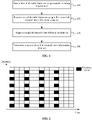
- FIG. 1 is a flowchart of a downlink channel state information estimation method according to an embodiment of the present application.
- the embodiment of the present application may be applicable to a case of estimating downlink channel state information in the FDD system.
- the method may be performed by a downlink channel state information estimation apparatus in an embodiment of the present application.
- the apparatus may be implemented by software and/or hardware and is generally integrated in a control node.
- the control node may be a wireless equipment for controlling a user equipment, where the wireless equipment includes the base station and an access point.
- the method in the embodiment of the present application includes the following.
- a downlink radio frame carrying channel sounding information is sent.
- the channel sounding information is a predefined sequence on a predetermined transmission resource.
- a medium carrying the channel sounding information is the downlink radio frame used for sounding downlink channel state information, and the channel sounding information is delivered from the control node to the user equipment through the downlink radio frame.
- the channel sounding information is a predefined sequence distributed on a predetermined transmission resource.
- the predefined sequence is a sequence of symbols with a specific meaning, and a receiver and a sender may pre-agree on the meaning of the predefined sequence before transmission.
- the predefined sequence consists of three symbols ⁇ -1, 0, 1 ⁇ , and a predefined sequence may be ⁇ 1 1 -1 -1 1 1 -1 1 -1 1 1 1 1 1 1 -1 -1 -1 1 -1 1 -1 1 1 1 10 1 -1 -1 -1 1 1 11-11-1-1-1-1-1-1 1 1-1 -1 1 -1 11 1 1 ⁇ .
- the predefined sequence includes at least one of a channel state reference signal or a demodulation reference signal.
- the transmission resource includes at least one of time resource, frequency resource, space resource, power resource, or codeword resource.
- FIG. 2 is an example diagram of time-frequency distribution of a channel state reference signal according to an embodiment of the present application, and channel state reference information sent by the base station at a predetermined time interval and frequency interval is shown in FIG. 2 .
- an uplink radio frame carrying a first downlink channel state information data set is received.
- the uplink radio frame is radio frame information sent by the user equipment to the control node and includes the downlink channel state information.
- the downlink channel state information includes a channel frequency response.
- the control node may monitor the uplink radio frame sent by the user equipment and acquire the first downlink channel state information data set in the uplink radio frame.
- the first downlink channel state information data set is composed of channel state information of some downlink subcarriers.
- an uplink channel state information data set is acquired.
- the uplink channel state information data set is obtained by estimating the uplink radio frame.
- the uplink channel state information data set is formed using stored historical values of an uplink channel state.
- 120 and 130 are only used for distinguishing and are not used for limiting the sequence of execution. 130 may be performed before 120, and 120 and 130 may also be performed simultaneously.
- a second downlink channel state information data set is determined.
- a downlink subcarrier corresponding to the second downlink channel state information data set is different from a downlink subcarrier corresponding to the first downlink channel state information data set.
- the second downlink channel state information data set is determined by using the uplink channel state information data set and the first downlink channel state information data set.
- parameters such as a propagation delay and an attenuation coefficient of a propagation path are estimated based on the uplink channel state information data set; the estimated parameters such as the propagation delay and the attenuation coefficient are corrected using the first downlink channel state information data set fed back by the user equipment; and the second downlink channel state information data set is calculated using the corrected parameters.
- the first downlink channel state information data set includes channel state information of an estimating subcarrier and an unwrapping subcarrier.
- the first downlink channel state information data set fed back by the user equipment to the control node includes two parts of channel state information: channel state information of the estimating subcarrier and channel state information of the unwrapping subcarrier.
- the channel state information of the estimating subcarrier is used for calculating basic values of parameters such as the propagation delay and the attenuation coefficient of the propagation path within a basic period, where the basic period refers to [0,2 ⁇ ].
- the channel state information of the unwrapping subcarrier is used for filtering out parameter items that satisfy requirements in a set generated by the parameter basic values within a range of multiple basic periods.
- the multiple basic periods refer to [- 2 j ⁇ ,0] ⁇ [2 ⁇ ,2 k ⁇ ], where k and j are integers greater than 1 and 0, respectively.
- the estimating subcarrier and the unwrapping subcarrier are randomly distributed in a frequency range where the downlink channel is located.
- parameters such as the propagation delay and the attenuation coefficient of the propagation path are jointly estimated using the first downlink channel state information data set and the uplink channel state information data set; and the second downlink channel state information data set is calculated using the jointly estimated parameters.
- the number of estimating subcarriers is determined by the number of propagation paths in the downlink channel.
- the number of unwrapping subcarriers is determined by a delay search interval.
- the delay search interval may be determined by the control node, and the predetermined delay search interval is sent to the user equipment.
- the delay search interval may also be determined by the user equipment, and the predetermined delay search interval is sent to the control node.
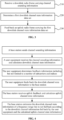
- FIG. 3 is a flowchart of a downlink channel state information estimation method according to an embodiment of the present application.
- the embodiment of the present application may be applicable to a case of estimating downlink channel state information in the FDD system.
- the method may be performed by a downlink channel state information estimation apparatus in an embodiment of the present application.
- the apparatus may be implemented by software and/or hardware and is generally integrated in a user equipment.
- the method in the embodiment of the present application includes the following.
- a downlink radio frame carrying channel sounding information is received.
- the user equipment receives the downlink radio frame delivered by the control node, where the downlink radio frame includes the channel sounding information.
- the channel sounding information may be a channel state reference signal and/or a demodulation reference signal, and the channel sounding information may be used for detecting the downlink channel state so as to acquire a channel frequency response from the control node to the user equipment.
- the channel sounding information is a predefined sequence distributed on a predetermined transmission resource.
- a first downlink channel state information data set is determined.
- the first downlink channel state information data set is a data set composed of downlink channel state information.
- the user equipment may randomly select a downlink subcarrier, acquire channel state information corresponding to the downlink subcarrier, and use the acquired channel state information of the downlink subcarrier as the first downlink channel state information data set.
- the first downlink channel state information data set includes channel state information of an estimating subcarrier and an unwrapping subcarrier.
- an uplink radio frame carrying the first downlink channel state information data set is fed back.
- the user equipment sends the first downlink channel state information data to the control node through the uplink radio frame.
- a downlink radio frame carrying channel sounding information is received; a downlink channel state information data set is determined; and an uplink radio frame carrying the downlink channel state information data set is fed back.
- determining the downlink channel state information includes the following.
- a propagation delay and an attenuation coefficient of a propagation path are estimated according to downlink channel frequency response.
- the user equipment acquires frequency response of a downlink wireless channel and calculates the propagation delay and the attenuation coefficient of the corresponding propagation path according to the frequency response.
- the number of estimating subcarriers is determined by the number of propagation paths in the channel.
- the number of pieces of channel state information of the estimating subcarriers in the first downlink channel state information data set corresponds to the number of propagation paths.
- the number of the estimating subcarriers is equal to the number of propagation paths.
- a subcarrier index and/or a subcarrier position are randomly selected so as to select the estimating subcarrier, and the corresponding channel state information is stored in the first downlink channel state information data set.
- the number of unwrapping subcarriers is determined by a delay search interval.
- the user equipment determines the number of unwrapping subcarriers based on the delay search interval. Generally, the larger the delay search interval is, the greater the number of selected unwrapping subcarriers is, where the delay search interval may be determined by the control node and sent by the control node to the user equipment.
- the unwrapping subcarrier in the first downlink channel state information data set is obtained by randomly selecting the subcarrier index and/or the subcarrier position.
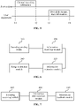
- FIG. 4 is an example diagram of a downlink channel state information estimation method according to an embodiment of the present application.
- a base station sends a downlink radio frame carrying channel sounding information to a user terminal, and the user equipment acquires downlink channel state information according to the downlink radio frame.
- the user equipment sends an uplink radio frame carrying the downlink channel state information to the base station on the corresponding uplink transmission resource.
- the base station estimates the uplink channel state information and then calculates the channel state information of downlink subcarriers other than the known fed back downlink subcarrier under the constraint of the fed back downlink channel state information.
- information exchange is implemented between the base station and the user equipment through the downlink radio frame carrying the channel sounding information and the uplink radio frame carrying the downlink channel state information.
- Variables A m and ⁇ m denote the attenuation coefficient and the propagation delay of the propagation path, respectively. If estimation values ⁇ m and ⁇ m of the variables A m and ⁇ m are put into formula (1), the corresponding channel frequency response is expressed as below.
- H' ( f, ⁇ m ) ⁇ m e -j2 ⁇ ⁇ m ⁇
- a nonlinear problem about a delay error ⁇ m ′ in a basic period [0,2 ⁇ ] of an exponential function may be formulated as below.
- the number V of estimating subcarriers is set equal to the number M of propagation paths.
- a coefficient matrix H' ( f ) formed by the estimating subcarriers is denoted as below.
- H ′ ⁇ A ⁇ 1 e ⁇ j 2 ⁇ 1 ⁇ ⁇ 1 A ⁇ 2 e ⁇ j 2 ⁇ 1 ⁇ ⁇ 2 ⁇ A ⁇ M e ⁇ j 2 ⁇ 1 ⁇ ⁇ M A ⁇ 1 e ⁇ j 2 ⁇ 2 ⁇ ⁇ 1 A ⁇ 2 e ⁇ j 2 ⁇ 2 ⁇ ⁇ 2 ⁇ A ⁇ M e ⁇ j 2 ⁇ 2 ⁇ ⁇ M ⁇ ⁇ ⁇ ⁇ A ⁇ 1 e ⁇ j 2 ⁇ M ⁇ ⁇ 1 A ⁇ 2 e ⁇ j 2 ⁇ M ⁇ ⁇ 2 ⁇ A ⁇ M e ⁇ j 2 ⁇ M ⁇ M ⁇ ⁇ ⁇ M ⁇ ⁇ M ⁇ ⁇ M ⁇ ⁇ M ⁇ ⁇ M ⁇ ⁇ M ⁇ ⁇ M ⁇ ⁇ M ⁇ ⁇ M ⁇ ⁇ M ⁇ ⁇ M ⁇ ⁇ M ⁇ ⁇
- the adjacent estimating subcarriers should make no correlation exist between rows of the matrix H'(f) or minimize the correlation between the rows of the matrix H' ( f ) in the case where an estimated delay is unknown.
- M integers may be randomly selected within an interval [Q, U] as position indices of the estimating subcarriers, where Q and U denote lower and upper bounds of the downlink subcarrier indices, respectively.
- a random seed for selecting downlink subcarriers may be determined by the base station, and the user equipment is notified during a feedback process or before a feedback operation is performed.
- the size of I may be determined by the base station or determined by the user equipment according to the downlink state information.
- N integers may be randomly selected within the interval [Q, U] as indices of the unwrapping subcarriers.
- Q and U denote lower and upper bounds of the downlink subcarrier indices, respectively; and indices of the unwrapping subcarriers are different from indices of the estimating subcarriers.
- the base station determines the random seed and notifies the user during the feedback process or before the feedback operation is performed. The base station calculates the estimation error of the propagation delay through formula (6).
- the attenuation coefficient is corrected by formula (7):
- the calibration solution for ⁇ ⁇ m ′ and A ⁇ m ′ may be iteratively performed until a corresponding objective function converges to an acceptable range.
- parameters ⁇ ⁇ m ′ and A ⁇ m ′ are put into formula (1) so as to calculate the desired frequency response of the downlink channel.
- the second downlink channel state information data set may be calculated through a joint constraint of the first downlink channel state data set and the uplink channel state data set.
- a complete set B ⁇ e ⁇ j 2 ⁇ 1 ⁇ 1 e ⁇ j 2 ⁇ 1 ⁇ 2 ⁇ e ⁇ j 2 ⁇ 1 ⁇ L e ⁇ j 2 ⁇ 2 ⁇ 1 e ⁇ j 2 ⁇ 2 ⁇ 2 ⁇ e ⁇ j 2 ⁇ 2 ⁇ L ⁇ ⁇ ⁇ ⁇ e ⁇ j 2 ⁇ K ⁇ 1 e ⁇ j 2 ⁇ K ⁇ 2 ⁇ e ⁇ j 2 ⁇ K ⁇ L .
- f denotes a frequency set having a size of K and including uplink subcarriers and fed back downlink subcarriers, and ⁇ l ( l ⁇ ⁇ 1,2,..., L ⁇ ) denotes uniform sampling in a time (delay) domain; an operator ⁇ p denotes a norm p.
- a non-zero term S l in S denotes the attenuation coefficient of the l -th propagation path, and the corresponding ⁇ l in B ( f ) denotes the propagation delay of the l -th transmission path.
- the user determines the downlink subcarrier to be fed back according to channel parameters calculated through the downlink channel response.
- ⁇ and ⁇ denote estimation values of the propagation delay and the attenuation coefficient of the propagation path, respectively.
- FIG. 6 is a structural diagram of a downlink channel state information estimation apparatus according to an embodiment of the present application.
- the apparatus may perform the downlink channel state information estimation method according to any embodiment of the present application and has functional modules and effects corresponding to the executed method.
- the apparatus may be implemented by software and/or hardware and is generally integrated in a control node.
- the apparatus includes a sounding sending module 310, an information receiving module 320, an information estimation module 330, and a range estimation module 340.
- the sounding sending module 310 is configured to send a downlink radio frame carrying channel sounding information.
- the information receiving module 320 is configured to receive an uplink radio frame carrying a first downlink channel state information data set.
- the information estimation module 330 is configured to acquire an uplink channel state information data set.
- the range estimation module 340 is configured to determine a second downlink channel state information data set.
- the sounding sending module 310 sends the downlink radio frame carrying the channel sounding information to the user equipment
- the information receiving module 320 receives the uplink radio frame including the first downlink channel state information data set
- the information estimation module 330 estimates the uplink channel state information data set
- the range estimation module 340 determines the second downlink channel state information data set so that the downlink channel state information estimation in the FDD system is achieved and the feedback amount of the downlink channel state information is reduced, thereby further reducing the feedback burden of the system.
- the channel sounding information in the sounding sending module 310 is a predefined sequence distributed on a predetermined transmission resource.
- the first downlink channel state information data set in the information receiving module 320 includes channel state information of an estimating subcarrier and an unwrapping subcarrier.
- the range estimation module 340 includes an information determination unit.
- the information determination unit is configured to determine the second downlink channel state information data set by using the uplink channel state information data set and the first downlink channel state information data set.
- FIG. 7 is a structural diagram of a downlink channel state information estimation apparatus according to an embodiment of the present application.
- the apparatus may perform the downlink channel state information estimation method according to any embodiment of the present application and has functional modules and effects corresponding to the executed method.
- the apparatus may be implemented by software and/or hardware and is generally integrated in a user equipment.
- the apparatus includes a sounding receiving module 410, an information determination module 420, and an information feedback module 430.
- the sounding receiving module 410 is configured to receive a downlink radio frame carrying channel sounding information.
- the information determination module 420 is configured to determine a first downlink channel state information data set.
- the information feedback module 430 is configured to feed back an uplink radio frame carrying the first downlink channel state information data set.
- the sounding receiving module 410 receives the downlink radio frame carrying the channel sounding information
- the information determination module 420 determines the first downlink channel state information data set
- the information feedback module 430 feeds back the uplink radio frame carrying the first downlink channel state information data set so that the feedback amount of the downlink channel state information is reduced and the feedback burden of the system is reduced.
- the channel sounding information in the sounding receiving module 410 is a predefined sequence distributed on a predetermined transmission resource.
- the first downlink channel state information data set in the information determination module 420 includes channel state information of an estimating subcarrier and an unwrapping subcarrier.
- the information feedback module 430 includes a parameter determination unit.
- the parameter determination unit is configured to estimate a propagation delay and an attenuation coefficient of a propagation path according to downlink channel frequency response.
- the number of estimating subcarriers is determined by the number of propagation paths in the channel.
- the number of unwrapping subcarriers is determined by a delay search interval.
- FIG. 8 is a structural diagram of a device according to an embodiment of the present application.
- the device includes a processor 50, a memory 51, an input apparatus 52, and an output apparatus 53.
- One or more processors 50 may be disposed in the device and one processor 50 is used as an example in FIG. 8 .
- the processor 50, the memory 51, the input apparatus 52 and the output apparatus 53 in the device may be connected via a bus or in other manners. Connecting by a bus is used as an example in FIG. 8 .
- the memory 51 may be configured to store software programs, computer-executable programs and modules, such as modules (for example, the sounding sending module 310, the information receiving module 320, the information estimation module 330, the range estimation module 340, the sounding receiving module 410, the information determination module 420, and the information feedback module 430) corresponding to the apparatus in the embodiments of the present application.
- the processor 50 executes various function applications and data processing of the device, that is, implements the downlink channel state information estimation method, by executing software programs, instructions and modules stored in the memory 51.
- the memory 51 may mainly include a program storage region and a data storage region.
- the program storage region may store an operating system and an application program required by at least one function.
- the data storage region may store data created depending on the use of a terminal.
- the memory 51 may include a high-speed random-access memory and may also include a nonvolatile memory such as at least one disk memory, a flash memory or another nonvolatile solid-state memory.
- the memory 51 may include memories which are remotely disposed relative to the processor 50, and these remote memories may be connected to the device via a network. Examples of the preceding network include, but are not limited to, the Internet, an intranet, a local area network, a mobile communication network and a combination thereof.
- the input apparatus 52 may be used for receiving inputted digital or character information and for generating key signal input related to user settings and function control of the equipment.
- the output apparatus 53 may include display devices such as a display screen.
- An embodiment of the present application further provides a computer-readable storage medium, which is configured to store a computer program which, when executed by a computer processor, implements the downlink channel state information estimation method.
- the method includes the following.
- a downlink radio frame carrying channel sounding information is sent; an uplink radio frame carrying a first downlink channel state information data set is received; an uplink channel state information data set is acquired; and a second downlink channel state information data set is determined.
- a downlink radio frame carrying channel sounding information is received; a first downlink channel state information data set is determined; and an uplink radio frame carrying the first downlink channel state information data set is fed back.
- computer-executable instructions implement not only the preceding method operations but also related operations in the downlink channel state information estimation method according to any embodiment of the present application.
- the present application may be implemented by means of both software and necessary general-purpose hardware, and also by means of hardware.
- the technical solutions of the present application may be essentially embodied in the form of a software product.
- the software product in a computer may be stored in a computer-readable storage medium such as a floppy disk, a read-only memory (ROM), a random-access memory (RAM), a flash memory, a hard disk or an optical disc in the computer and includes several instructions for enabling a computer device (which may be a personal computer, a server or a network device) to perform the method of the embodiments of the present application.
- Units and modules involved in the embodiment of the downlink channel state information estimation apparatus are just divided according to functional logic, and the division is not limited to this, as long as the corresponding functions can be achieved.
- the names of each functional unit are just intended for distinguishing and are not to limit the protection scope of the embodiments of the present application.
- the term user terminal encompasses any appropriate type of wireless user equipment, such as a mobile phone, a portable data processing apparatus, a portable web browser or a vehicle-mounted mobile station.
- multiple embodiments of the present application may be implemented in hardware or special-purpose circuits, software, logic or any combination thereof.
- some aspects may be implemented in hardware while other aspects may be implemented in firmware or software that may be executed by a controller, a microprocessor or another computing apparatus, though the present application is not limited thereto.
- the embodiments of the present application may be implemented by computer program instructions executed by a data processor of a mobile apparatus, for example, implemented in a processor entity, by hardware or by a combination of software and hardware.
- the computer program instructions may be assembly instructions, instruction set architecture (ISA) instructions, machine instructions, machine-related instructions, microcodes, firmware instructions, status setting data or source or object codes written in any combination of one or more programming languages.
- a block diagram of any logic flow among the drawings of the present application may represent program steps, may represent interconnected logic circuits, modules and functions, or may represent a combination of program steps with logic circuits, modules and functions.
- a computer program may be stored in a memory.
- the memory may be of any type suitable for a local technical environment and may be implemented using any suitable data storage technology, such as, but not limited to, a read-only memory (ROM), a random access memory (RAM) and an optical memory apparatus and system (a digital video disc (DVD) or a compact disk (CD)).
- Computer-readable media may include non-transitory storage media.
- the data processor may be of any type suitable to the local technical environment such as, but not limited to, a general-purpose computer, a special-purpose computer, a microprocessor, a digital signal processor (DSP), an application-specific integrated circuit (ASIC), a field-programmable gate array (FPGA) and a processor based on a multi-core processor architecture.
- a general-purpose computer such as, but not limited to, a general-purpose computer, a special-purpose computer, a microprocessor, a digital signal processor (DSP), an application-specific integrated circuit (ASIC), a field-programmable gate array (FPGA) and a processor based on a multi-core processor architecture.
- DSP digital signal processor
- ASIC application-specific integrated circuit
- FPGA field-programmable gate array
Landscapes
- Engineering & Computer Science (AREA)
- Computer Networks & Wireless Communication (AREA)
- Signal Processing (AREA)
- Power Engineering (AREA)
- Mobile Radio Communication Systems (AREA)
Applications Claiming Priority (2)
| Application Number | Priority Date | Filing Date | Title |
|---|---|---|---|
| CN202010420856.XA CN111901259B (zh) | 2020-05-18 | 2020-05-18 | 下行信道状态信息估计方法、装置、设备和存储介质 |
| PCT/CN2021/077083 WO2021232868A1 (zh) | 2020-05-18 | 2021-02-20 | 下行信道状态信息估计方法、装置、设备和存储介质 |
Publications (2)
| Publication Number | Publication Date |
|---|---|
| EP4156789A1 true EP4156789A1 (de) | 2023-03-29 |
| EP4156789A4 EP4156789A4 (de) | 2024-06-19 |
Family
ID=73207496
Family Applications (1)
| Application Number | Title | Priority Date | Filing Date |
|---|---|---|---|
| EP21807979.6A Pending EP4156789A4 (de) | 2020-05-18 | 2021-02-20 | Verfahren, vorrichtung und gerät zur schätzung der kanalzustandsinformation eines downlink-kanals und speichermedium |
Country Status (4)
| Country | Link |
|---|---|
| US (1) | US12401549B2 (de) |
| EP (1) | EP4156789A4 (de) |
| CN (1) | CN111901259B (de) |
| WO (1) | WO2021232868A1 (de) |
Families Citing this family (2)
| Publication number | Priority date | Publication date | Assignee | Title |
|---|---|---|---|---|
| CN111901259B (zh) | 2020-05-18 | 2024-12-24 | 中兴通讯股份有限公司 | 下行信道状态信息估计方法、装置、设备和存储介质 |
| CN117176530A (zh) * | 2022-05-25 | 2023-12-05 | 中国移动通信有限公司研究院 | 无线信道探测方法、装置、终端及存储介质 |
Family Cites Families (19)
| Publication number | Priority date | Publication date | Assignee | Title |
|---|---|---|---|---|
| US6996380B2 (en) * | 2001-07-26 | 2006-02-07 | Ericsson Inc. | Communication system employing transmit macro-diversity |
| KR100918747B1 (ko) | 2006-02-07 | 2009-09-24 | 삼성전자주식회사 | 직교 주파수 분할 다중 접속 방식을 사용하는 이동 통신시스템에서 상향링크 신호 송신 장치 및 방법 |
| US7885631B2 (en) * | 2007-01-26 | 2011-02-08 | Samsung Electronics Co., Ltd | Method for receiving signal in communication system and system therefor |
| US20100260060A1 (en) * | 2009-04-08 | 2010-10-14 | Qualcomm Incorporated | Integrated calibration protocol for wireless lans |
| CN103444104B (zh) * | 2011-03-31 | 2015-05-20 | 瑞典爱立信有限公司 | 用于确定在即将到来的时隙中的信道状态信息的方法和网络节点 |
| CN102868500A (zh) * | 2011-07-07 | 2013-01-09 | 华为技术有限公司 | 信道信息的反馈方法、终端和基站 |
| EP3007366B1 (de) * | 2013-05-29 | 2020-10-28 | Alcatel Lucent | Csi-rückmeldungsverfahren und -vorrichtung in einem grossflächigen antennensystem |
| US9445283B2 (en) | 2013-08-23 | 2016-09-13 | Huawei Technologies Co., Ltd. | Channel sounding for frequency division duplex system |
| CN105634658A (zh) * | 2014-10-31 | 2016-06-01 | 中国移动通信集团公司 | 一种进行发送处理的方法、设备及系统 |
| US10334467B2 (en) * | 2014-12-08 | 2019-06-25 | Telefonaktiebolaget L M Ericsson (Publ) | Method and radio network node for estimating channel quality |
| CN111770038A (zh) * | 2014-12-16 | 2020-10-13 | 富士通株式会社 | 下行信道估计方法、装置、通信系统以及终端 |
| EP3281302A1 (de) * | 2015-04-08 | 2018-02-14 | NTT Docomo, Inc. | Basisstation, benutzergerät und verfahren zur bestimmung einer vorcodierungsmatrix |
| CN107733549B (zh) * | 2016-08-10 | 2020-09-25 | 华为技术有限公司 | 信道质量信息计算方法、装置及系统 |
| WO2018083714A1 (en) * | 2016-11-03 | 2018-05-11 | Wisig Networks Private Limited | Method and system for enabling explicit channel state information (csi) feedback in multiple-input-multiple-output (mimo) |
| TWI632803B (zh) * | 2016-12-16 | 2018-08-11 | 財團法人工業技術研究院 | 通道資訊傳輸方法及應用其的無線通訊系統 |
| CN109120565A (zh) * | 2017-06-23 | 2019-01-01 | 上海科技大学 | Fdd系统下行信道估计方法及基站、可读存储介质及设备 |
| CN111147212B (zh) | 2018-11-02 | 2022-11-15 | 大唐移动通信设备有限公司 | 非激活频率资源的信道测量方法、基站及终端 |
| US11405088B2 (en) * | 2019-02-07 | 2022-08-02 | Qualcomm Incorporated | Beam management using channel state information prediction |
| CN111901259B (zh) | 2020-05-18 | 2024-12-24 | 中兴通讯股份有限公司 | 下行信道状态信息估计方法、装置、设备和存储介质 |
-
2020
- 2020-05-18 CN CN202010420856.XA patent/CN111901259B/zh active Active
-
2021
- 2021-02-20 EP EP21807979.6A patent/EP4156789A4/de active Pending
- 2021-02-20 US US17/795,700 patent/US12401549B2/en active Active
- 2021-02-20 WO PCT/CN2021/077083 patent/WO2021232868A1/zh not_active Ceased
Also Published As
| Publication number | Publication date |
|---|---|
| CN111901259B (zh) | 2024-12-24 |
| EP4156789A4 (de) | 2024-06-19 |
| US12401549B2 (en) | 2025-08-26 |
| CN111901259A (zh) | 2020-11-06 |
| US20230055509A1 (en) | 2023-02-23 |
| WO2021232868A1 (zh) | 2021-11-25 |
Similar Documents
| Publication | Publication Date | Title |
|---|---|---|
| US11509360B2 (en) | Terminal device capability transmission method, apparatus, and system | |
| EP3553968A1 (de) | Einzelträgerbreitbandstrahlformungsverfahren und -system | |
| US12335007B2 (en) | Channel state information report coefficients | |
| US20230291517A1 (en) | Communication method, communications apparatus, and communications device | |
| EP2963964B1 (de) | Verfahren zur sicherstellung einer kanalphasenkontinuität zwischen rb-gruppen nach einer vorcodierung, basisstation und computerlesbares speichermedium | |
| US20230085924A1 (en) | Channel information processing method and apparatus | |
| US12401549B2 (en) | Downlink channel state information estimation method and apparatus, device, and storage medium | |
| EP4243299A1 (de) | Drahtlose kommunikationsvorrichtung zum senden und empfangen von daten unter verwendung von kanalstatusinformationsrückkopplung und betriebsverfahren dafür | |
| EP4607868A1 (de) | Verfahren, vorrichtung und vorrichtung zur rückkopplung von kanalstatusinformationen und speichermedium | |
| US10404435B2 (en) | Pilot signal generation method and apparatus | |
| US12581421B2 (en) | Method for determining a sending power of an uplink element, and device | |
| EP3131339A1 (de) | Kanalmessung, messverfahren, kanalmessvorrichtung sowie benutzergerät und system | |
| US20200119779A1 (en) | Channel state information related feedback reporting and channel state information acquisition | |
| CN113924810A (zh) | 数据传输处理方法、装置、通信设备及存储介质 | |
| US8385489B2 (en) | Methods and apparatus for wireless channel estimation using interpolation elimination in the Eigen domain | |
| EP3890207A1 (de) | Verfahren und vorrichtung zur optimierung einer antennenvorcodiererauswahl mit gekoppelter antennen | |
| EP3065308A1 (de) | Funkbasisstation, mobilstation und verfahren zur bestimmung der sendeleistung | |
| EP4542907A1 (de) | Kanalmessungsübertragungsverfahren, basisstation, endgerät, speichermedium und programmprodukt | |
| US20220150855A1 (en) | Method and Apparatus for Estimating and Compensating Timing Advance | |
| EP3479495B1 (de) | Verfahren zum erhalt von uplink kalibrierwerten, kalibrierverfahren und entsprechendes endgerät und basisstation | |
| EP4383636A1 (de) | Benutzerplanungsverfahren bei der mehrantennensignalübertragung sowie elektronische vorrichtung und speichermedium | |
| EP3902151B1 (de) | Verfahren zur verarbeitung von codebuch-informationen, endgerät und computerlesbares speichermedium | |
| EP3096465B1 (de) | Mimo-übertragungsverfahren, system und vorrichtung | |
| EP3073646B1 (de) | Verfahren zur optimierung des rangs der kanalmatrix, drahtlose basis- und mobilstation | |
| WO2025036356A1 (zh) | 信道状态信息上报、接收方法、装置、设备及可读存储介质 |
Legal Events
| Date | Code | Title | Description |
|---|---|---|---|
| STAA | Information on the status of an ep patent application or granted ep patent |
Free format text: STATUS: THE INTERNATIONAL PUBLICATION HAS BEEN MADE |
|
| PUAI | Public reference made under article 153(3) epc to a published international application that has entered the european phase |
Free format text: ORIGINAL CODE: 0009012 |
|
| STAA | Information on the status of an ep patent application or granted ep patent |
Free format text: STATUS: REQUEST FOR EXAMINATION WAS MADE |
|
| 17P | Request for examination filed |
Effective date: 20220728 |
|
| AK | Designated contracting states |
Kind code of ref document: A1 Designated state(s): AL AT BE BG CH CY CZ DE DK EE ES FI FR GB GR HR HU IE IS IT LI LT LU LV MC MK MT NL NO PL PT RO RS SE SI SK SM TR |
|
| DAV | Request for validation of the european patent (deleted) | ||
| DAX | Request for extension of the european patent (deleted) | ||
| A4 | Supplementary search report drawn up and despatched |
Effective date: 20240516 |
|
| RIC1 | Information provided on ipc code assigned before grant |
Ipc: H04W 40/12 20090101AFI20240511BHEP |
|
| STAA | Information on the status of an ep patent application or granted ep patent |
Free format text: STATUS: EXAMINATION IS IN PROGRESS |
|
| 17Q | First examination report despatched |
Effective date: 20260319 |