EP4243299A1 - Drahtlose kommunikationsvorrichtung zum senden und empfangen von daten unter verwendung von kanalstatusinformationsrückkopplung und betriebsverfahren dafür - Google Patents
Drahtlose kommunikationsvorrichtung zum senden und empfangen von daten unter verwendung von kanalstatusinformationsrückkopplung und betriebsverfahren dafür Download PDFInfo
- Publication number
- EP4243299A1 EP4243299A1 EP23160929.8A EP23160929A EP4243299A1 EP 4243299 A1 EP4243299 A1 EP 4243299A1 EP 23160929 A EP23160929 A EP 23160929A EP 4243299 A1 EP4243299 A1 EP 4243299A1
- Authority
- EP
- European Patent Office
- Prior art keywords
- precoder
- base station
- reference signal
- pdsch
- csi
- Prior art date
- Legal status (The legal status is an assumption and is not a legal conclusion. Google has not performed a legal analysis and makes no representation as to the accuracy of the status listed.)
- Pending
Links
Images


Classifications
-
- H—ELECTRICITY
- H04—ELECTRIC COMMUNICATION TECHNIQUE
- H04B—TRANSMISSION
- H04B7/00—Radio transmission systems, i.e. using radiation field
- H04B7/02—Diversity systems; Multi-antenna system, i.e. transmission or reception using multiple antennas
- H04B7/04—Diversity systems; Multi-antenna system, i.e. transmission or reception using multiple antennas using two or more spaced independent antennas
- H04B7/06—Diversity systems; Multi-antenna system, i.e. transmission or reception using multiple antennas using two or more spaced independent antennas at the transmitting station
- H04B7/0613—Diversity systems; Multi-antenna system, i.e. transmission or reception using multiple antennas using two or more spaced independent antennas at the transmitting station using simultaneous transmission
- H04B7/0615—Diversity systems; Multi-antenna system, i.e. transmission or reception using multiple antennas using two or more spaced independent antennas at the transmitting station using simultaneous transmission of weighted versions of same signal
- H04B7/0619—Diversity systems; Multi-antenna system, i.e. transmission or reception using multiple antennas using two or more spaced independent antennas at the transmitting station using simultaneous transmission of weighted versions of same signal using feedback from receiving side
- H04B7/0621—Feedback content
- H04B7/0626—Channel coefficients, e.g. channel state information [CSI]
-
- H—ELECTRICITY
- H04—ELECTRIC COMMUNICATION TECHNIQUE
- H04B—TRANSMISSION
- H04B7/00—Radio transmission systems, i.e. using radiation field
- H04B7/02—Diversity systems; Multi-antenna system, i.e. transmission or reception using multiple antennas
- H04B7/04—Diversity systems; Multi-antenna system, i.e. transmission or reception using multiple antennas using two or more spaced independent antennas
- H04B7/06—Diversity systems; Multi-antenna system, i.e. transmission or reception using multiple antennas using two or more spaced independent antennas at the transmitting station
- H04B7/0613—Diversity systems; Multi-antenna system, i.e. transmission or reception using multiple antennas using two or more spaced independent antennas at the transmitting station using simultaneous transmission
- H04B7/0615—Diversity systems; Multi-antenna system, i.e. transmission or reception using multiple antennas using two or more spaced independent antennas at the transmitting station using simultaneous transmission of weighted versions of same signal
- H04B7/0619—Diversity systems; Multi-antenna system, i.e. transmission or reception using multiple antennas using two or more spaced independent antennas at the transmitting station using simultaneous transmission of weighted versions of same signal using feedback from receiving side
- H04B7/0621—Feedback content
- H04B7/0632—Channel quality parameters, e.g. channel quality indicator [CQI]
-
- H—ELECTRICITY
- H04—ELECTRIC COMMUNICATION TECHNIQUE
- H04B—TRANSMISSION
- H04B7/00—Radio transmission systems, i.e. using radiation field
- H04B7/02—Diversity systems; Multi-antenna system, i.e. transmission or reception using multiple antennas
- H04B7/04—Diversity systems; Multi-antenna system, i.e. transmission or reception using multiple antennas using two or more spaced independent antennas
- H04B7/06—Diversity systems; Multi-antenna system, i.e. transmission or reception using multiple antennas using two or more spaced independent antennas at the transmitting station
- H04B7/0613—Diversity systems; Multi-antenna system, i.e. transmission or reception using multiple antennas using two or more spaced independent antennas at the transmitting station using simultaneous transmission
- H04B7/0615—Diversity systems; Multi-antenna system, i.e. transmission or reception using multiple antennas using two or more spaced independent antennas at the transmitting station using simultaneous transmission of weighted versions of same signal
- H04B7/0617—Diversity systems; Multi-antenna system, i.e. transmission or reception using multiple antennas using two or more spaced independent antennas at the transmitting station using simultaneous transmission of weighted versions of same signal for beam forming
-
- H—ELECTRICITY
- H04—ELECTRIC COMMUNICATION TECHNIQUE
- H04B—TRANSMISSION
- H04B7/00—Radio transmission systems, i.e. using radiation field
- H04B7/02—Diversity systems; Multi-antenna system, i.e. transmission or reception using multiple antennas
- H04B7/04—Diversity systems; Multi-antenna system, i.e. transmission or reception using multiple antennas using two or more spaced independent antennas
- H04B7/06—Diversity systems; Multi-antenna system, i.e. transmission or reception using multiple antennas using two or more spaced independent antennas at the transmitting station
- H04B7/0613—Diversity systems; Multi-antenna system, i.e. transmission or reception using multiple antennas using two or more spaced independent antennas at the transmitting station using simultaneous transmission
- H04B7/0615—Diversity systems; Multi-antenna system, i.e. transmission or reception using multiple antennas using two or more spaced independent antennas at the transmitting station using simultaneous transmission of weighted versions of same signal
- H04B7/0619—Diversity systems; Multi-antenna system, i.e. transmission or reception using multiple antennas using two or more spaced independent antennas at the transmitting station using simultaneous transmission of weighted versions of same signal using feedback from receiving side
- H04B7/0636—Feedback format
- H04B7/0639—Using selective indices, e.g. of a codebook, e.g. pre-distortion matrix index [PMI] or for beam selection
-
- H—ELECTRICITY
- H04—ELECTRIC COMMUNICATION TECHNIQUE
- H04L—TRANSMISSION OF DIGITAL INFORMATION, e.g. TELEGRAPHIC COMMUNICATION
- H04L5/00—Arrangements affording multiple use of the transmission path
- H04L5/003—Arrangements for allocating sub-channels of the transmission path
- H04L5/0048—Allocation of pilot signals, i.e. of signals known to the receiver
-
- H—ELECTRICITY
- H04—ELECTRIC COMMUNICATION TECHNIQUE
- H04W—WIRELESS COMMUNICATION NETWORKS
- H04W52/00—Power management, e.g. Transmission Power Control [TPC] or power classes
- H04W52/04—Transmission power control [TPC]
- H04W52/52—Transmission power control [TPC] using AGC [Automatic Gain Control] circuits or amplifiers
Definitions
- the present disclosure relates to a wireless communication device transmitting and receiving data using channel state information (CSI) feedback.
- CSI channel state information
- Precoding may be generally understood as a preprocessing method for optimizing single stream or multiple stream beamforming and thereby increase data throughput. Precoding may involve measuring the communication channel using reference signals, and thereafter weighting amplitude and phase of signals transmitted from each of multiple transmit antennas, according to the measured channel.
- a user equipment may transmit a sounding reference signal (SRS) to a base station (BS).
- SRS sounding reference signal
- the BS may estimate an uplink channel between the UE and the BS using the received SRS.
- the BS may design a precoder for a downlink channel using the estimated uplink channel.
- the precoder may be designed using the reciprocity of the estimated uplink channel and a time division duplex (TDD) channel.
- TDD time division duplex
- the BS can send the reference signals to the UE to identify the channel information between the BS and the UE.
- the BS may transmit a channel state information-reference signal (CSI-RS) to identify channel information between the BS and the UE.
- the UE may identify a channel between the BS and the UE through a CSI-RS received from the BS.
- the UE may report feedback information on the identified channel to the BS.
- the feedback information may include a precoding matrix indicator (PMI), a rank indicator (RI), and a channel quality indicator (CQI).
- the BS may design an SRS-based precoder using the received feedback information, and may transmit a physical downlink shared channel (PDSCH) to the UE using the precoder.
- PDSCH physical downlink shared channel
- Embodiments of the inventive concept provide a wireless communication device that transmits and receives data using CSI feedback, and an operating method thereof.
- a method of operating a wireless communication device including transmitting a sounding reference signal (SRS) to a base station; receiving, from the base station, a first reference signal to which a second precoder is applied; generating feedback information including at least one of a rank indicator (RI) and a channel quality indicator (CQI) based on at least one of: (i) a relationship between the second precoder and a first precoder applied to a first physical downlink shared channel (PDSCH) by the base station based on the SRS, and (ii) a channel estimated by using the first reference signal; transmitting the generated feedback information to the base station; and receiving a second PDSCH to which at least one of the first precoder, the RI, and the CQI is applied.
- SRS sounding reference signal
- a first reference signal to which a second precoder is applied
- CQI channel quality indicator
- a method of operating a base station including receiving a sounding reference signal (SRS) from a wireless communication device, generating a first precoder based on the SRS; transmitting, to the wireless communication device, a first reference signal to which a second precoder is applied, determining a precoding matrix indicator (PMI) candidate group based on the first precoder and the second precoder; receiving feedback information on the first reference signal including at least one of a rank indicator (RI) and a channel quality indicator (CQI), and transmitting a physical downlink shared channel (PDSCH) to which at least one of the second precoder, the RI, and the CQI is applied.
- SRS sounding reference signal
- PMI precoding matrix indicator
- a wireless communication device including a radio frequency integrated circuit (RFIC) configured to transmit a sounding reference signal (SRS) to a base station, and receive, from the base station, a first reference signal to which a second precoder is applied and a processor configured to generate feedback information including at least one of a rank indicator (RI) and a channel quality indicator (CQI) on the basis of at least one of a relationship between the second precoder and a first precoder applied to a first PDSCH by the base station based on the SRS, and the estimated channel using the first reference signal.
- the RFIC may transmit the generated feedback information to the base station and receive a second PDSCH to which at least one of the first precoder, the RI, and the CQI is applied.
- a base station is a network element that communicates with a wireless communication device and allocates a communication network resource to the wireless communication device.
- a base station is sometimes referred to as a cell, a NodeB (NB), an eNodB (eNB), a next generation radio access network (NG RAN), a wireless access unit, a base station controller, a node on a network, a gNodeB (gNB), a transmission and reception point (TRP), a remote radio head (RRH), or the like.
- a wireless communication device is a device that communicates with a base station or another wireless communication device and may be referred to as a node, a user equipment (UE), a next generation UE (NG UE), a mobile station (MS), a mobile equipment (ME), a device, a terminal, or the like.
- UE user equipment
- NG UE next generation UE
- MS mobile station
- ME mobile equipment
- a wireless communication device examples include a smartphone, a tablet PC, a mobile phone, an image telephone, an electronic book reader, a desktop PC, a laptop PC wallet, a netbook computer, a PDA, a portable multimedia player (PMP), an MP3 player, a medical device, a camera, and a wearable device.
- a smartphone a tablet PC
- a mobile phone an image telephone
- an electronic book reader a desktop PC
- a laptop PC wallet a netbook computer
- PDA portable multimedia player
- MP3 player an MP3 player
- medical device a camera
- a wearable device examples include a wearable device.
- a television a digital video disk (DVD) player, an audio player, a refrigerator, an air conditioner, a cleaner, an oven, a microwave oven, a washing machine, an air purifier, a set-top box, a home automation control panel, a security control panel, a media box (e.g., Samsung HomeSync TM , Apple TV TM , or Google TV TM ), a game console (e.g., an Xbox TM , PlayStation TM ), an electronic dictionary, an electronic key, a video camera (camcorder), and an electronic picture frame.
- DVD digital video disk
- Still other examples include at least one of various medical devices (e.g., various portable medical measuring instruments (blood glucose meters, heart rate meters, blood pressure meters, or body temperature meters), magnetic resonance angiography (MRA), magnetic resonance imaging (MRI), computed tomography (CT), a photographing device, or an ultrasonic device), a navigation device, a global navigation satellite system (GNSS), an event data recorder (EDR), a flight data recorder (FDR), a vehicle infotainment device, an electronic equipment for a ship (e.g., a navigation device for a ship, a gyro compass, etc.), an avionics, a security device, a head unit for a vehicle, an industrial or home robot, a drone, an automated teller machine (ATM) of a financial institution, a point of sales (POS) terminal of a store, or Internet of things devices (e.g., bulbs, various sensors, sprinkler devices, fire alarms, temperature controllers, street lamps, toasters, exercise equipment, hot
- FIGS. 1A and 1B illustrate a wireless communication system according to an embodiment of the inventive concept.
- the wireless communication system may include a wireless communication device 120 and a base station 110.
- wireless communication device 120 is referred to as a user equipment (UE) 120.
- UE user equipment
- the wireless communication system is shown and described in the context of one base station 110 and one UE 120, but embodiments may be implemented with two or more base stations and/or UEs.
- the base station 110 may be wirelessly connected to the UE 120 through a wireless channel to provide various communication services.
- the base station 110 may provide a service through a shared channel for all user traffic, and may collect and schedule state information such as a buffer state, an available transmission power state, and a channel state of the UE 120.
- the wireless communication system may support beamforming techniques by using orthogonal frequency division multiplexing (OFDM) schemes as wireless access techniques.
- the wireless communication system may support an adaptive modulation and coding (AMC) scheme that determines a modulation scheme and a channel coding rate according to the channel state of the UE 120.
- AMC adaptive modulation and coding
- the wireless communication system transmits and receives signals using a wide frequency band including a 6 GHz band.
- a wireless communication system may use a millimeter wave band, such as a 28 GHz band or a 60 GHz band, to increase data transfer rates.
- the wireless communication system may support directional beam-based transmission and reception generated using multiple antennas to secure coverage.
- the wireless communication system may be a system that supports multiple inputs and multiple outputs (MIMO), and accordingly, the base station 110 and the UE 120 may support beamforming techniques.
- beamforming techniques may include digital beamforming, analog beamforming, and/or hybrid beamforming.
- the base station 110 may transmit a channel state information-reference signal (CSI-RS) to the UE 120.
- the UE 120 may estimate a channel between the base station 110 and the UE 120 using the CSI-RS.
- the UE 120 may generate CSI feedback information (CSI-RS report) including at least one of a rank indicator (RI), a precoding matrix indicator (PMI), and channel quality information (CQI) using the estimated channel.
- the UE 120 may transmit the generated CSI feedback information in a CSI-RS report to the base station 110.
- the UE 120 may transmit a sounding reference signal (SRS) to the base station 110.
- the base station 110 may estimate a channel between the base station 110 and the UE 120 using the SRS obtained in a time division duplex (TDD) transmission.
- the base station 110 may design a precoder to maximize the capacity of the estimated channel.
- the base station 110 may transmit a physical downlink shared channel (PDSCH) to the UE 120 using the designed precoder.
- PDSCH physical downlink shared channel
- the base station 110 may additionally use the CSI feedback information to schedule the PDSCH.
- the base station 110 may calculate information on a relationship between the precoder of the CSI-RS and the precoder based on the SRS and transmit the calculated information to the UE 120, in order to use the CSI feedback information when transmitting the PDSCH using the precoder based on the SRS.
- the UE 120 may generate CSI feedback information that corresponds to the PDSCH based on the received information.
- the UE 120 may measure a beamforming gain for the PDSCH and may measure a beamforming gain of the CSI-RS, and thus predict a relationship between the precoder of the PDSCH and the precoder of the CSI-RS.
- the UE 120 may generate CSI feedback information corresponding to the PDSCH by using information on the relationship between the precoder of the PDSCH and the precoder of the CSI-RS.
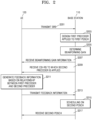
- FIG. 2 is a flowchart illustrating an operating method of a UE and a base station according to an embodiment of the inventive concept.
- the UE 120 may transmit an SRS to the base station 110, which receives the same.
- the base station 110 may estimate an uplink channel and a downlink channel between the base station 110 and the UE 120 using the received SRS.
- the base station 110 may regard an estimated uplink channel between the base station 110 and the UE 120 as a downlink channel between the base station 110 and the UE 120, by using "SRS switching" based on reciprocity.
- the base station 110 may design a downlink precoder using the uplink SRS.
- the base station may design a first precoder based on the SRS.
- the base station 110 may design a first precoder applied to a first PDSCH. For instance, the base station 110 may design the first precoder to maximize the capacity of the estimated channel using the SRS.
- the first precoder may be a precoder that is not based on a codebook.
- the first precoder may include an eigen-vector of a channel between the base station 110 and the UE 120.
- the first precoder may have a higher resolution than a codebook-based precoder. Accordingly, when the first precoder is used for data transmission, data throughput may be higher than when a codebook-based precoder is used for data transmission.
- the base station 110 may design the first precoder to maximize one or more metrics, such as a mean of the mutual information per coded bit (MMIB), by using the estimated channel.
- MMIB mutual information per coded bit
- the base station 110 may determine a beamforming gain.
- the base station 110 may calculate a beamforming gain for a physical downlink shared channel (PDSCH) to which the first precoder based on the SRS is applied.
- the base station 110 may calculate a first beamforming gain to be realized by the UE 120 when the UE 120 receives a PDSCH to which the precoder based on the SRS is applied.
- PDSCH physical downlink shared channel
- the base station 110 may transmit, to the UE 120, a CSI-RS to which a second precoder is applied (S209).
- the second precoder may be a precoder predetermined by the base station.
- the second precoder may be a precoder based on a CSI-RS report received by the base station 110 from the UE 120.
- the base station 110 may calculate a second beamforming gain realizable by the UE 120 when the UE 120 receives the CSI-RS to which the second precoder is applied.
- the first precoder may differ from the second precoder.
- the base station 110 may calculate a first beamforming gain for the first precoder that maximizes the channel capacity of the estimated channel based on the SRS and a second beamforming gain for the second precoder applied to the CSI-RS.
- the UE 120 may receive beamforming gain information from the base station 110 (S207).
- the base station 110 may transmit, to the UE 120, first beamforming gain information on the first precoder based on the SRS.
- the base station 110 may transmit, the UE 120, second beamforming gain information on the second precoder applied to the CSI-RS.
- the base station 110 may transmit CSI-RS to the UE 120 (S209), beamforming gain information (S207) including first beamforming gain information of the first precoder (e.g., beamforming gain due to the first precoder) based on the SRS and second beamforming gain information of the second precoder (e.g., beamforming gain due to the second precoder) applied to the CSI-RS.
- the base station 110 may transmit, to the UE 120, information on a ratio of the first beamforming ga(n to the second beamforming gain.
- the ratio of the first beamforming gain to the second beamforming gain may be expressed as follows:
- B F Diff gain k ⁇ H k F ⁇ L ⁇ SRS k ⁇ F 2 L ⁇ ⁇ H k F tx CSI k ⁇ F 2 N CSI Port
- B F Diff gain k is a ratio (or difference) of the first beamforming gain to the second beamforming gain
- H k ⁇ C N rx ⁇ N tx is a channel between the UE 120 and the base station 110, where N rx is the number of receiving antennas and N tx is the number of transmitting antennas
- F ⁇ L ⁇ SRS k is a precoder that maximizes the capacity of a channel estimated based on a SRS
- F tx CSI k ⁇ C N tx ⁇ N CSI Port is a second precoder used when the base station transmits a CSI-RS
- L ⁇ is the number of layers of data transmitted by the base station
- N CSI Port is the number of antenna ports of the CSI-RS.
- the beamforming gain information including the ratio of the first beamforming gain to the second beamforming gain may be referred to as a beamforming gain offset.
- the beamforming gain offset may be a ratio of a beamforming gain of a PDSCH resource element to a beamforming gain of a non-zero power (NZP) CSI-RS resource element.
- the beamforming gain offset may have a value in units of dB.
- the base station 110 may transmit beamforming gain information to the UE 120 using any one of signaling schemes including radio resource control (RRC), media access control control element (MACCE), and downlink control information (DCI).
- RRC radio resource control
- MACCE media access control control element
- DCI downlink control information
- the base station 110 may transmit, to the UE 120, a radio resource control (RRC) signal including beamforming gain information.
- RRC radio resource control
- the beamforming gain offset may be included in a NZP-CSI-RS-Resource information element.
- the UE 120 may receive, from the base station 110, the CSI-RS to which the second precoder is applied (S209).
- the UE 120 may estimate a channel between the base station 110 and the UE 120 using the received CSI-RS.
- the UE 120 may generate feedback information based on a relationship between the first precoder and the second precoder.
- the relationship between the first precoder and the second precoder may refer to a ratio between the first beamforming gain of the first precoder and the second beamforming gain of the second precoder.
- the UE 120 may generate CSI-RS feedback information using the received beamforming gain information.
- Equation 2 B F Diff gain k is a ratio (or difference) of the first beamforming gain to the second beamforming gain; L ⁇ is a rank to be reported by the UE 120 using a rank indicator (RI); F L PMI k is a PMI codebook having a rank L; and H CSI [ k ] is described below in connection with Equation 3.
- the channel capacity C will be described later in connection with Equation 4.
- Equation 3 Y rx CSIRS k ⁇ C N rx ⁇ N CSI Port is a CSI-RS reception signal, where N CSI Port is the number of antenna ports of the CSI-RS; H k ⁇ C N rx ⁇ N tx is a channel between the UE 120 and the base station 110; F tx CSI k ⁇ C N tx ⁇ N CSI Port is a precoder used by the base station for CSI-RS transmission; N rx CSI k ⁇ C N rx ⁇ N CSI Port is noise included in the reception signal; and H CSI [ k ] is a product of a channel between the UE 120 and the base station 110 and a precoder used for CSI-RS transmission.
- the UE 120 120 may not separately receive H k ⁇ C N rx ⁇ N tx and F tx CSI k ⁇ C N tx ⁇ N CSI Port . Accordingly, the UE 120 may estimate a value of H CSI [ k ].
- the UE 120 may transmit feedback information to the base station 110.
- the UE 120 may transmit, to the base station 110, feedback information including a rank indicator (RI) and a CQI calculated using the beamforming gain information and the estimated channel.
- RI rank indicator
- CQI calculated using the beamforming gain information and the estimated channel.
- a CSI report of an embodiment of the inventive concept is described herein based on a subband CSI report. In other embodiments, the CSI report is applied to a wideband CSI report.
- the base station 110 may perform scheduling on a second PDSCH.
- the base station 110 may perform scheduling on the second PDSCH using at least one of the first precoder based on the SRS and feedback information received from the UE 120.
- the base station 110 may perform scheduling on the second PDSCH using at least one of the first precoder based on the SRS, and the RI and the CQI received from the UE 120.
- the base station 110 may determine a rank for the second PDSCH using the received RI.
- the base station 110 may determine a modulation and coding scheme (MCS) for the second PDSCH using the received CQI. Accordingly, the base station 110 may determine at least one of the rank and the CQI suitable for the UE 120.
- MCS modulation and coding scheme
- the UE 120 may receive the second PDSCH from the base station 110.
- FIG. 3 is a flowchart illustrating an operating method of a UE and a base station according to an embodiment of the inventive concept.
- the UE 120 may transmit an SRS to the base station 110.
- the base station 110 may receive an SRS from the UE 120.
- the base station 110 may estimate an uplink channel and a downlink channel between the base station 110 and the UE 120 using the received SRS.
- the base station 110 may regard an estimated uplink channel between the base station 110 and the UE 120 as a downlink channel, by using the SRS based on reciprocity.
- the base station may design a first precoder based on the SRS.
- the base station 110 may design a first precoder applied to a first PDSCH. Specifically, the base station 110 may design the first precoder to maximize the capacity of the estimated channel using the SRS.
- the first precoder may be a precoder that is not based on a codebook.
- the first precoder may include an eigen-vector of a channel between the base station 110 and the UE 120.
- the first precoder may have a higher resolution than a codebook-based precoder. Accordingly, when the first precoder is used for data transmission, data throughput may be higher relative to a codebook-based precoder implementation.
- the base station 110 may design the first precoder to maximize at least one metric, such as an MMIB using the estimated channel.
- the UE 120 may receive the first PDSCH from the base station 110.
- the base station 110 may apply a first precoder to the first PDSCH.
- the base station 110 may transmit, to the UE 120, the first PDSCH to which the first precoder is applied.
- the UE 120 may measure a beamforming gain for the first precoder. To this end, the UE 120 may measure a beamforming gain of the first PDSCH to which the first precoder based on the SRS is applied. For example, the UE 120 may measure the beamforming gain of the first PDSCH by measuring the received power of the first PDSCH.
- the UE 120 may receive, from the base station 110, a CSI-RS to which the second precoder is applied.
- the first precoder may differ from the second precoder.
- the UE 120 may estimate a channel between the base station 110 and the UE 120 using the received CSI-RS.
- the UE 120 may measure a beamforming gain for the second precoder. Specifically, the UE 120 may measure a beamforming gain of the CSI-RS to which the second precoder is applied. For example, the UE 120 may measure the beamforming gain of the CSI-RS by measuring the reception power of the CSI-RS.
- the UE 120 may estimate a ratio of a beamforming gain for the first precoder based on the SRS to a beamforming gain for the second precoder applied to the CSI-RS. Specifically, the UE 120 may estimate a ratio of the beamforming gains using the measured beamforming gain of the first precoder and the measured beamforming gain of the second precoder.
- the ratio of the beamforming gains may be expressed as in Equation 1 described above.
- the UE 120 may generate feedback information based on a relationship between the first precoder and the second precoder.
- the relationship between the first precoder and the second precoder may refer to a ratio between the first beamforming gain of the first precoder and the second beamforming gain of the second precoder.
- the UE 120 may generate CSI-RS feedback information using the measured beamforming gain of the first precoder and the measured beamforming gain of the second precoder.
- the UE 120 may generate CSI-RS feedback information using the ratio information of the measured beamforming gain of the first precoder and the measured beamforming gain of the second precoder.
- the UE 120 may calculate at least one of PMI, RI, and CQI using the measured beamforming gain and the estimated channel.
- the rank and PMI may be calculated using the channel and beamforming gain information estimated by the UE 120, and the rank and PMI may be expressed as in Equation 2.
- the UE 120 may transmit feedback information to the base station 110.
- the UE 120 may transmit, to the base station 110, feedback information including a rank indicator (RI) and a CQI calculated using the measured beamforming gain information and the estimated channel.
- RI rank indicator
- CQI CQI
- the base station 110 may perform scheduling on a second PDSCH.
- the base station 110 may perform scheduling on the second PDSCH using at least one of the first precoder based on the SRS and feedback information received from the UE 120.
- the base station 110 may perform scheduling on the second PDSCH using at least one of the first precoder based on the SRS, and the RI and the CQI received from the UE 120.
- the base station 110 may determine a rank for the second PDSCH using the received RI.
- the base station 110 may determine a modulation and coding scheme (MCS) for the second PDSCH using the received CQI. Accordingly, the base station 110 may determine at least one of the rank and the CQI suitable for the UE 120.
- MCS modulation and coding scheme
- the UE 120 may receive the second PDSCH from the base station 110.
- FIG. 4A is a flowchart illustrating an operating method of a UE and a base station according to an embodiment of the inventive concept.
- the UE 120 may transmit an SRS to the base station 110.
- the base station 110 may receive an SRS from the UE 120.
- the base station 110 may estimate an uplink channel and a downlink channel between the base station 110 and the UE 120 using the received SRS.
- the base station 110 may regard an estimated uplink channel between the base station 110 and the UE 120 as a downlink channel between the base station 110 and the UE 120, by using the SRS based on reciprocity.
- the base station may design a first precoder based on the SRS.
- the base station 110 may design a first precoder applied to a first PDSCH. Specifically, the base station 110 may design the first precoder to maximize the capacity of the estimated channel using the SRS.
- the first precoder may be a precoder that is not based on a codebook.
- the first precoder may include an eigen-vector of a channel between the base station 110 and the UE 120.
- the first precoder may have a higher resolution than a codebook-based precoder. Accordingly, when the first precoder is used for data transmission, data throughput may be higher as compared to a codebook-based precoder implementation.
- the base station 110 may design the first precoder to maximize a metric, such as an MMIB using the estimated channel.
- the base station 110 may design the first precoder to maximize various metrics, and is not limited to the above-described embodiments.
- the UE 120 may receive the first PDSCH from the base station 110.
- the base station 110 may apply a first precoder to the first PDSCH.
- the base station 110 may transmit, to the UE 120, the first PDSCH to which the first precoder is applied.
- the UE 120 may measure a beamforming gain for the first precoder. Specifically, the UE 120 may measure a beamforming gain of the first PDSCH to which the first precoder based on the SRS is applied. For example, the UE 120 may measure the beamforming gain of the first PDSCH by measuring the received power of the first PDSCH.
- the UE 120 may receive, from the base station 110, a CSI-RS to which the second precoder is applied.
- the first precoder may differ from the second precoder.
- the UE 120 may estimate a channel between the base station 110 and the UE 120 using the received CSI-RS.
- the UE 120 may measure a beamforming gain for the second precoder. Specifically, the UE 120 may measure a beamforming gain of the CSI-RS to which the second precoder is applied. For example, the UE 120 may measure the beamforming gain of the CSI-RS by measuring the reception power of the CSI-RS.
- the UE 120 may estimate a ratio of a beamforming gain for the first precoder based on the SRS to a beamforming gain for the second precoder applied to the CSI-RS. Specifically, the UE 120 may estimate a ratio of the beamforming gains using the measured beamforming gain of the first precoder and the measured beamforming gain of the second precoder.
- the ratio of the beamforming gains may be expressed as in Equation 1 described above.
- the UE 120 may transmit a channel alignment request message to the base station 110. For instance, when the measured beamforming gain of the first PDSCH differs from the measured beamforming gain of the CSI-RS, the UE 120 may transmit a channel alignment request message to the base station 110. The UE 120 may request the base station 110 to change the precoder of the CSI-RS by transmitting the channel alignment request message to the base station 110. For example, the UE 120 may request the base station 110 to apply the first precoder of the first PDSCH to the CSI-RS by transmitting the channel alignment request message to the base station 110.
- the base station 110 may apply the first precoder to the CSI-RS.
- the base station 110 may design a precoder for the PDSCH without using a PMI codebook.
- the channel alignment request message may be referred to as a non-PMI based feedback request message.
- the UE 120 may transmit a non-PMI based feedback request message to the base station 110 by using any one of signaling schemes including RRC, MAC CE, and DCI.
- the UE 120 may transmit, to the base station 110, a UE assistance information message including a non-PMI based feedback request message.
- the UE assistance information may be an RRC signaling parameter.
- the base station 110 may determine a beam of the CSI-RS. For example, when receiving a channel alignment request message from the UE 120, the base station 110 may apply, to the CSI-RS, the precoder of the first PDSCH transmitted to the UE 120.
- the UE 120 may receive, from the base station 110, a CSI-RS to which the first precoder is applied.
- the UE 120 may determine that the precoders of the CSI-RS and the PDSCH are the same.
- the UE 120 may generate feedback information by using the CSI-RS to which the first precoder is applied. For example, the UE 120 may estimate a channel between the base station 110 and the UE 120 by using the CSI-RS to which the first precoder is applied. Further, the UE 120 may calculate feedback information including at least one of RI and CQI for maximizing the estimated channel.
- the UE 120 may transmit feedback information to the base station 110.
- the UE 120 may transmit, to the base station 110, feedback information including the calculated RI and CQI.
- the base station 110 may perform scheduling on a second PDSCH. As described above, the base station 110 may perform scheduling on the second PDSCH using at least one of the first precoder based on the SRS and feedback information received from the UE 120. For example, the base station 110 may perform scheduling on the second PDSCH using at least one of the first precoder based on the SRS, and the RI and the CQI received from the UE 120. The base station 110 may determine a rank for the second PDSCH using the received RI. The base station 110 may determine a modulation and coding scheme (MCS) for the second PDSCH using the received CQI. Accordingly, the base station 110 may determine at least one of the rank and the CQI suitable for the UE 120.
- MCS modulation and coding scheme
- the UE 120 may receive the second PDSCH from the base station 110.
- FIG. 4B illustrates an operating method of a UE according to an embodiment of the inventive concept. Specifically, FIG. 4B illustrates an example of an operating method of the UE 120 in a situation where the UE 120 measures the beamforming gain of the first precoder and the beamforming gain of the second precoder in FIG. 4A .
- the UE 120 may measure a beamforming gain of each of the PDSCH and the CSI-RS.
- the UE 120 may measure reception power of each of the first PDSCH and the CSI-RS.
- the UE 120 may calculate the beamforming gain of the first precoder by measuring the reception power of the first PDSCH.
- the UE 120 may calculate the beamforming gain of the second precoder by measuring the reception power of the CSI-RS.
- the UE 120 may check whether the beamforming gain of the PDSCH is different from the beamforming gain of the CSI-RS (e.g. differs by more than a predefined amount).
- the UE 120 may transmit a channel alignment request message to the base station 110 when the beamforming gain of the PDSCH differs from the beamforming gain of the CSI-RS ("Y" in FIG. 4B ).
- the UE 120 may request the base station 110 to apply the first precoder to the CSI-RS by transmitting the channel alignment request message to the base station 110.
- the UE 120 may determine the RI and CQI based on the received CSI-RS. In this case, it may be already considered that the precoder of the CSI-RS is the same as the precoder of the PDSCH.
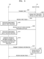
- FIG. 5A illustrates an operating method of a base station according to an embodiment of the inventive concept.
- the UE 120 may transmit an SRS to the base station 110.
- the base station 110 may receive an SRS from the UE 120.
- the base station 110 may estimate an uplink channel and a downlink channel between the base station 110 and the UE 120 using the received SRS.
- the base station 110 may regard an estimated uplink channel between the base station 110 and the UE 120 as a downlink channel between the base station 110 and the UE 120, by using the SRS based on reciprocity.
- the base station may design a first precoder based on the SRS switching.
- the base station 110 may design a first precoder applied to a first PDSCH. Specifically, the base station 110 may design the first precoder to maximize the capacity of the estimated channel using the SRS.
- the first precoder may be a precoder that is not based on a codebook.
- the first precoder may include an eigen-vector of a channel between the base station 110 and the UE 120.
- the first precoder may have a higher resolution than a codebook-based precoder. Accordingly, when the first precoder is used for data transmission, data throughput may be higher than when a codebook-based precoder is used for data transmission.
- the base station 110 may design the first precoder to maximize at least one metric, such as an MMIB, using the estimated channel.
- the base station 110 may determine a beam of the CSI-RS. For example, the base station 110 may apply a first precoder to the CSI-RS. In this case, the base station 110 may inform the UE 120 that the first precoder used for PDSCH transmission and the precoder used for CSI-RS transmission have the same beamforming gain.
- the UE 120 may receive beamforming gain information from the base station 110.
- the UE 120 may receive, from the base station 110, information that the first precoder used for PDSCH transmission and the precoder used for CSI-RS transmission have the same beamforming gain.
- the beamforming gain information may be expressed as in Equation 5: ⁇ H k F ⁇ L ⁇ SRS k ⁇ F 2 L ⁇ ⁇ ⁇ H k F tx CSI k ⁇ F 2 N CSI Port where
- the UE 120 may receive such beamforming gain information through higher layer signaling related to a transmission configuration information (TCI) state.
- TCI transmission configuration information
- the UE 120 may receive such beamforming gain information through quasi-co-location (QCL) type signaling (e.g. QCL-type-E signaling, as described with reference to FIG. 5B ), which is a higher layer parameter.
- QCL quasi-co-location
- the UE 120 may receive, from the base station 110, a CSI-RS to which the first precoder is applied.
- the UE 120 may confirm that the precoder applied to the first PDSCH and the precoder applied to the CSI-RS are the same based on the QCL-type information (e.g. including the QCL-type-E) received from the base station 110.
- the UE 120 may estimate a channel between the base station 110 and the UE 120 using the received CSI-RS.
- the UE 120 may generate feedback information by using the CSI-RS to which the first precoder is applied.
- the UE 120 may calculate at least one of the PMI, RI, and CQI.
- the rank and PMI may be calculated using the channel and beamforming gain information estimated by the UE 120, and the rank and PMI may be expressed as in Equation 2.
- the UE 120 may transmit feedback information to the base station 110.
- the UE 120 may transmit, to the base station 110, feedback information including a rank indicator (RI) and a CQI calculated using the beamforming gain information and the estimated channel.
- RI rank indicator
- CQI CQI calculated using the beamforming gain information and the estimated channel.
- the base station 110 may perform scheduling on a second PDSCH. As described above, the base station 110 may perform scheduling on the second PDSCH using at least one of the first precoder based on the SRS and feedback information received from the UE 120. For example, the base station 110 may perform scheduling on the second PDSCH using at least one of the first precoder based on the SRS, and the RI and the CQI received from the UE 120. The base station 110 may determine a rank for the second PDSCH using the received RI. The base station 110 may determine an MCS for the second PDSCH using the received CQI. Accordingly, the base station 110 may determine at least one of the rank and the CQI suitable for the UE 120.
- the UE 120 may receive the second PDSCH from the base station 110.
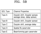
- FIG. 5B illustrates a quasi-co-location (QCL)-type applicable to an embodiment of the inventive concept.
- FIG. 5B specifically illustrates an example of the quasi-co-location (QCL) type described above in step S507 of FIG. 5A .
- the channel characteristics of QCL-Type-A include Doppler shift, Doppler spread, average delay, and delay spread.
- the channel characteristics of the QCL-Type-B include Doppler shift and Doppler spread.
- the channel characteristics of the QCL-Type-C include Doppler shift and average delay.
- the channel characteristics of the QCL-Type-D include a spatial Rx parameter.
- the QCL-Type-D may mean that the wireless communication device shares, with a target signal, the spatial Rx parameter acquired from a source signal.
- the source signal may be referred to as a source channel.
- the target signal may be referred to as a target channel.
- the channel characteristic of the QCL-Type-E may include a beamforming gain parameter.
- the QCL-Type-E may include an identity between a beamforming gain of a reference signal precoder and a beamforming gain of a PDSCH precoder.
- the base station may perform signaling of a TCI state and thereby inform the UE that the base station transmits the PDSCH and a physical downlink control channel (PDCCH) to the UE by using the same beam as the reference signal. That is, the base station may inform the UE that the PDSCH and the PDCCH are transmitted based on the same spatial filter as the specific reference signal.
- the TCI state may include information on the reference signal.
- the TCI state may include information on at least one of a synchronization signal block (SSB) and a channel state information-reference signal (CSI-RS).
- SSB synchronization signal block
- CSI-RS channel state information-reference signal
- the base station may inform the UE of which TCI the PDSCH and the PDCCH are related through TCI state signaling.
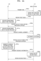
- FIG. 6 illustrates an operating method of a UE and a base station according to an embodiment of the inventive concept.
- the UE 120 may transmit an SRS to the base station 110.
- the base station 110 may receive an SRS from the UE 120.
- the base station 110 may estimate an uplink channel and a downlink channel between the base station 110 and the UE 120 using the received SRS.
- the base station 110 may regard an estimated uplink channel between the base station 110 and the UE 120 as a downlink channel between the base station 110 and the UE 120, by using the SRS based on reciprocity.
- the base station may design a first precoder based on the SRS switching.
- the base station 110 may determine a precoder.
- the base station 110 may design a first precoder applied to the first PDSCH. Specifically, the base station 110 may design the first precoder to maximize the capacity of the estimated channel using the SRS.
- the first precoder may be a precoder that is not based on a codebook.
- the first precoder may include an eigen-vector of a channel between the base station 110 and the UE 120.
- the first precoder may have a higher resolution than a codebook-based precoder. Accordingly, when the first precoder is used for data transmission, data throughput may be higher than when a codebook-based precoder is used for data transmission.
- the base station 110 may design the first precoder to maximize at least one metric, such as an MMIB, using the estimated channel.
- the base station 110 may determine a beam of the CSI-RS.
- the base station 110 may apply, to the CSI-RS, a second precoder different from the first precoder.
- the base station 110 may calculate a PMI candidate group.
- the base station 110 may calculate each of a precoder based on "SRS switching" and a precoder applied to the CSI-RS and identify a value thereof. Referring to Equation 6, the base station 110 may calculate a PMI candidate group having the smallest difference between the precoder based on SRS switching and the precoder applied to the CSI-RS.
- the PMI candidate group may have one PMI fixed for each rank.
- the base station 110 may apply, to the CSI-RS based on any one PMI of the PMI candidate group, a precoder applied to the PDSCH and a second precoder having the most similar spatial domain characteristics.
- the UE 120 may receive the PMI candidate group.
- the PMI candidate group may be referred to as a codebook subset restriction.
- the base station 110 may fix one PMI for each rank by transmitting the PMI candidate group to the UE 120.
- the base station 110 may omit the PMI by setting all the bitmaps to 0.
- the UE 120 may receive, from the base station 110, a CSI-RS to which the second precoder is applied.
- the UE 120 may estimate a channel between the base station 110 and the UE 120 using the received CSI-RS.
- the UE 120 may generate feedback information by using the CSI-RS to which the second precoder is applied.
- the UE 120 may generate CSI-RS feedback information using the received PMI candidate group information.
- the UE 120 may calculate at least one of the RI and the CQI using the received PMI candidate group information and the received CSI-RS.
- the UE 120 may transmit CSI-RS feedback information to the base station 110.
- the UE 120 may transmit, to the base station 110, feedback information including the RI and the CQI calculated using the PMI codebook.
- the base station 110 may perform scheduling on a second PDSCH. As described above, the base station 110 may perform scheduling on the second PDSCH using at least one of the first precoder based on the SRS and feedback information received from the UE 120. For example, the base station 110 may perform scheduling on the second PDSCH using at least one of the first precoder based on the SRS, and the RI and the CQI received from the UE 120. The base station 110 may determine a rank for the second PDSCH using the received RI. The base station 110 may determine an MCS for the second PDSCH using the received CQI. Accordingly, the base station 110 may determine at least one of the rank and the CQI suitable for the UE 120.
- the UE 120 may receive data from the base station 110.
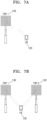
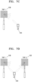
- FIGS. 7A to 7D illustrate example beamforming with transmission and reception points (TRPs) according to respective embodiments of the inventive concept.
- TRPs transmission and reception points
- Each of the shown TRPs in FIGS. 7A-7D is an example of the base station 110.
- the UE 120 may be connected to a network through a single transmission and reception point (TRP) 130 and a single beam.
- TRP transmission and reception point
- the UE 120 may be connected to a network through a plurality of TRPs 130 and 132 and one beam for each TRP.
- the UE 120 may be connected to a network through a single TRP 130 and a plurality of beams formed by the TRP 130.
- the UE 120 may be connected to a network through a plurality of TRPs 130 and 132 and a plurality of beams formed by each TRP.
- the first TRP 130 and the second TRP 132 may transmit different PDSCHs to the UE 120.
- the first TRP 130 may transmit a first PDSCH to the UE 120
- the first TRP 132 may transmit a second PDSCH to the UE 120.
- the first TRP 130 may transmit downlink control information (DCI) to the UE 120 through a physical downlink control channel (PDCCH).
- DCI downlink control information
- PDCCH physical downlink control channel
- the first PDSCH and the second PDSCH may be scheduled by the PDCCH transmitted by the first TRP 130.
- the first TRP 130 may transmit a first PDCCH controlling the first PDSCH to the UE 120
- the second TRP 132 may transmit a second PDCCH controlling the second PDSCH to the UE 120.
- Embodiments according to the inventive concept may be applied to communication between the UE 120 and the plurality of TRPs 130 and 132.
- the plurality of TRPs 130 and 132 may transmit a CSI-RS to the UE 120, and the plurality of TRPs 130 and 132 may transmit the above-described beamforming gain offset to the UE 120.
- the UE 120 may predict beamforming gains of each of the PDSCH and the CSI-RS with respect to each of the plurality of TRPs 130 and 132.
- the UE 120 may transmit the above-described channel alignment request message to each of the plurality of TRPs 130 and 132. To this end, the UE 120 may transmit a csi-ReportWithoutPMIRequest message for each of the plurality of TRPs 130 and 132.
- the UE 120 may signal to each of the plurality of TRPs 130 and 132 that a beamforming gain of a precoder used for PDSCH transmission is the same (within a predetermined tolerance range) as a beamforming gain of a precoder used for CSI-RS transmission.
- Such signaling may be defined as a QCL-Type as described above.
- the UE 120 may feedback, to each of the TRPs 130 and 132, pieces of information calculated using the received CSI-RS.
- each of the plurality of TRPs 130 and 132 may transmit, to the UE 120, the PMI candidate group.
- the plurality of TRPs 130 and 132 may apply, to the CSI-RS, a precoder, which is most similar in spatial domain characteristics to a precoder used for PDSCH transmission based on any one PMI of the PMI candidate group.
- the UE 130 may feed back at least one of the RI and the CQI for each TRP.
- n is a TRP index.
- TRPs may vary, and is not limited to the above-described embodiments.
- the embodiments according to the inventive concept may be applied to communication between the UE 120 and the plurality of radio remote heads (RRHs).
- RRHs radio remote heads
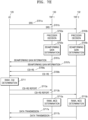
- FIG. 7E illustrates an operating method of a UE and TRPs according to an embodiment of the inventive concept.
- the UE 120 may transmit an SRS to the first TRP 130.
- the UE 120 may transmit an SRS to the second TRP 132.
- the first TRP 130 may determine a precoder. Specifically, the first TRP 130 may determine a precoder applied to the PDSCH using the SRS.
- the second TRP 132 may determine a precoder. Specifically, the second TRP 132 may determine a precoder applied to the PDSCH using the SRS.
- the first TRP 130 may calculate a beamforming gain of the precoder based on the SRS and a beamforming gain of the CSI-RS precoder.
- the first TRP 130 may determine beamforming gain information based on the calculated beamforming gain.
- the first TRP 130 may calculate a beamforming gain of the precoder based on the SRS and a beamforming gain of the CSI-RS precoder.
- the second TRP 132 may determine beamforming gain information based on the calculated beamforming gain.
- the UE 120 may receive beamforming gain information from the first TRP 130.
- the UE 120 may receive beamforming gain information from the second TRP 132.
- the UE 120 may calculate at least one of the RI and the CQI for each of the first TRP 130 and the second TRP 132 using the CSI-RS received from each of the first TRP 130 and second TRP 132.
- the UE 120 may generate CSI feedback information for each TRP.
- the UE 120 may transmit a CSI-RS report to the first TRP 130.
- the UE 120 may transmit a CSI-RS report to the second TRP 132.
- the first TRP 130 may determine at least one of a rank and an MCS.
- the first TRP 130 may schedule the PDSCH using the precoder based on the SRS and CSI feedback information received from the UE 120.
- the second TRP 132 may determine at least one of the rank and the MCS.
- the second TRP 132 may schedule the PDSCH using the precoder based on the SRS and CSI feedback information received from the UE 120.
- the first TRP 130 may transmit the PDSCH to the UE 120.
- the second TRP 132 may transmit the PDSCH to the UE 120.
- the operating method sequence for each TRP of the UE 120 is not limited to the above-described embodiment.
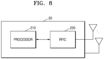
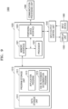
- FIG. 8 is a block diagram illustrating a wireless communication device according to an embodiment of the inventive concept.
- the wireless communication device 20 may include at least one processor 210 and at least one RFIC 220.
- the processor 210 may control the RFIC 220, and may be configured to implement operating methods and operating flowcharts of the wireless communication device 20 of the inventive concept.
- the wireless communication device 20 may include a plurality of antennas, and the RFIC 220 may transmit and receive wireless signals through one or more antennas. At least some of the plurality of antennas may correspond to a transmission antenna.
- the transmission antenna may transmit a wireless signal to an external device (e.g., another user equipment (UE) or a base station (BS) rather than the wireless communication device 20. At least some of the remaining plurality of antennas may correspond to a reception antenna.
- the reception antenna may receive a wireless signal from the external device.
- the wireless communication device 20 may include the RFIC 220 that transmits the sounding reference signal (SRS) to the base station and receives, from the base station, the first reference signal to which the first precoder is applied, and a processor 210 that generates feedback information including at least one of a RI and a CQI based on at least one of a relationship between the first precoder and a second precoder applied to a first physical downlink shared channel (PDSCH) by the base station based on the SRS and a channel estimated using the first reference signal.
- SRS sounding reference signal
- PDSCH physical downlink shared channel
- the RFIC 220 may transmit the generated feedback information to the base station and receive a second PDSCH to which at least one of the second precoder, the RI, and the CQI is applied.
- FIG. 9 is a block diagram illustrating an electronic device 1000 according to an embodiment of the inventive concept.
- the electronic device 1000 may include a memory 1010, a processor unit 1020, an input/output control unit 1040, a display unit 1050, an input device 1060, and a communication processing unit 1090.
- the memory 1010 may be provided with a plurality of memory units.
- the memory 1010 may include a program storage unit 1011 that stores a program for controlling an operation of the electronic device and a data storage unit 1012 that stores data generated during the execution of the program.
- the data storage unit 1012 may store data necessary for the operation of an application program 1013 and a CSI-RS density determination program 1014.
- the program storage unit 1011 may include an application program 1013 and a CSI-RS density determination program 1014.
- the programs included in the program storage unit 1011 may be expressed as an instruction set or as a set of instructions.
- the application program 1013 includes an application program that operates in the electronic device. That is, the application program 1013 may include an instruction of an application driven by the processor 1022.
- the CSI-RS feedback determination program 1014 may generate CSI-RS feedback based on the relationship between the precoder of the PDSCH and the precoder of the CSI-RS according to embodiments of the inventive concept.
- a peripheral device interface 1023 may control the connection between an input/output peripheral device of the base station, and each of a processor 1022 and a memory interface 1021.
- the processor 1022 controls the base station to provide a corresponding service using at least one software program.
- the processor 1022 may execute at least one program stored in the memory 1010 to provide a service corresponding to the corresponding program.
- the input/output control unit 1040 may provide an interface between an input/output device, such as the display unit 1050, the input device 1060, or the like, and the peripheral device interface 1023.
- the display unit 1050 displays state information, input characters, moving pictures, still pictures, and the like.
- the display unit 1050 may display application program information driven by the processor 1022.
- the input device 1060 may provide input data generated by selection of the electronic device to the processor unit 1020 through the input/output control unit 1040.
- the input device 1060 may include a keypad including at least one hardware button, a touch pad that senses touch information, and the like.
- the input device 1060 may provide touch information, such as touch, touch movement, touch release, and the like, which are sensed through the touch pad, to the processor 1022 through the input/output control unit 1040.
- the electronic device 1000 may include the communication processing unit 1090 that performs a communication function for voice communication and data communication.
Landscapes
- Engineering & Computer Science (AREA)
- Signal Processing (AREA)
- Computer Networks & Wireless Communication (AREA)
- Physics & Mathematics (AREA)
- Mathematical Physics (AREA)
- Mobile Radio Communication Systems (AREA)
Applications Claiming Priority (2)
| Application Number | Priority Date | Filing Date | Title |
|---|---|---|---|
| KR20220030328 | 2022-03-10 | ||
| KR1020220083160A KR20230133166A (ko) | 2022-03-10 | 2022-07-06 | Csi 피드백을 활용하여 데이터를 송수신하는 무선 통신 장치 및 이의 동작 방법 |
Publications (1)
| Publication Number | Publication Date |
|---|---|
| EP4243299A1 true EP4243299A1 (de) | 2023-09-13 |
Family
ID=85556503
Family Applications (1)
| Application Number | Title | Priority Date | Filing Date |
|---|---|---|---|
| EP23160929.8A Pending EP4243299A1 (de) | 2022-03-10 | 2023-03-09 | Drahtlose kommunikationsvorrichtung zum senden und empfangen von daten unter verwendung von kanalstatusinformationsrückkopplung und betriebsverfahren dafür |
Country Status (3)
| Country | Link |
|---|---|
| US (2) | US12512891B2 (de) |
| EP (1) | EP4243299A1 (de) |
| TW (1) | TW202337177A (de) |
Families Citing this family (3)
| Publication number | Priority date | Publication date | Assignee | Title |
|---|---|---|---|---|
| US10615859B2 (en) * | 2017-03-24 | 2020-04-07 | Telefonaktiebolaget Lm Ericsson (Publ) | Systems and methods for determining transmitter and receiver configurations for a wireless device |
| KR20250059709A (ko) * | 2023-10-25 | 2025-05-07 | 삼성전자주식회사 | 네트워크 협력 통신 시스템에서 채널 상태 정보 획득 방법 및 장치 |
| WO2024234617A1 (en) * | 2023-11-30 | 2024-11-21 | Zte Corporation | Channel state information reference signal reporting from multiple user equipment |
Citations (3)
| Publication number | Priority date | Publication date | Assignee | Title |
|---|---|---|---|---|
| US20180241454A1 (en) * | 2015-08-13 | 2018-08-23 | Samsung Electronics Co., Ltd. | Channel state information feedback method and apparatus |
| US20190356364A1 (en) * | 2018-05-18 | 2019-11-21 | Futurewei Technologies, Inc. | System and Method for Communications System Training |
| WO2021212454A1 (en) * | 2020-04-24 | 2021-10-28 | Qualcomm Incorporated | New csi report setting to hasten csi feedback for svd-based precoding |
Family Cites Families (13)
| Publication number | Priority date | Publication date | Assignee | Title |
|---|---|---|---|---|
| US9478857B2 (en) | 2012-03-02 | 2016-10-25 | Samsung Electronics Co., Ltd. | Apparatus and method for controlling adaptive beamforming gain in wireless communication system |
| KR20160094337A (ko) | 2015-01-30 | 2016-08-09 | 한국전자통신연구원 | 무선 자원 관리의 측정을 위한 방법 및 장치 |
| CN112235088B (zh) | 2015-08-13 | 2024-04-09 | 三星电子株式会社 | 处理参考信号的方法、基站和终端 |
| KR102335741B1 (ko) | 2015-08-13 | 2021-12-06 | 삼성전자주식회사 | 이동 통신 시스템에서 빔포밍된 csi-rs를 이용하는 통신 기법 |
| CN106686620B (zh) | 2015-11-06 | 2021-06-22 | 索尼公司 | 无线通信设备和无线通信方法 |
| WO2018169375A1 (ko) * | 2017-03-17 | 2018-09-20 | 엘지전자 주식회사 | 무선 통신 시스템에서 자원 번들링에 기반한 프리코더 적용 방법 및 이를 위한 장치 |
| CN109787668B (zh) | 2017-11-15 | 2023-10-20 | 华为技术有限公司 | 通信方法、通信装置和系统 |
| US10873481B2 (en) * | 2017-11-27 | 2020-12-22 | Qualcomm Incorporated | Reference signal transmission window and timing considerations |
| US11522587B2 (en) | 2018-08-08 | 2022-12-06 | Telefonaktiebolaget Lm Ericsson (Publ) | Method and device for channel state information feedback |
| WO2020154832A1 (en) * | 2019-01-28 | 2020-08-06 | Qualcomm Incorporated | Hybrid channel state feedback |
| EP3981087A2 (de) * | 2019-06-17 | 2022-04-13 | Huawei Technologies Co., Ltd. | Verfahren und geräte für den betrieb in einem breitbandkommunikationssystem |
| WO2022091033A1 (en) * | 2020-10-30 | 2022-05-05 | Lenovo (Singapore) Pte. Ltd. | Channel state information report configuration |
| WO2022152530A1 (en) * | 2021-01-15 | 2022-07-21 | Nokia Solutions And Networks Oy | Enhanced fd precoding on csi-rs by ue multiplexing |
-
2023
- 2023-03-02 US US18/177,372 patent/US12512891B2/en active Active
- 2023-03-09 EP EP23160929.8A patent/EP4243299A1/de active Pending
- 2023-03-09 TW TW112108748A patent/TW202337177A/zh unknown
-
2025
- 2025-11-20 US US19/395,065 patent/US20260081670A1/en active Pending
Patent Citations (3)
| Publication number | Priority date | Publication date | Assignee | Title |
|---|---|---|---|---|
| US20180241454A1 (en) * | 2015-08-13 | 2018-08-23 | Samsung Electronics Co., Ltd. | Channel state information feedback method and apparatus |
| US20190356364A1 (en) * | 2018-05-18 | 2019-11-21 | Futurewei Technologies, Inc. | System and Method for Communications System Training |
| WO2021212454A1 (en) * | 2020-04-24 | 2021-10-28 | Qualcomm Incorporated | New csi report setting to hasten csi feedback for svd-based precoding |
Also Published As
| Publication number | Publication date |
|---|---|
| US12512891B2 (en) | 2025-12-30 |
| US20230291457A1 (en) | 2023-09-14 |
| TW202337177A (zh) | 2023-09-16 |
| US20260081670A1 (en) | 2026-03-19 |
Similar Documents
| Publication | Publication Date | Title |
|---|---|---|
| US12136972B2 (en) | Wireless communication system, and device and method in wireless communication system | |
| US10826582B2 (en) | Wireless communication device and wireless communication method | |
| US12413449B2 (en) | Wireless communication method and wireless communication device | |
| EP4243299A1 (de) | Drahtlose kommunikationsvorrichtung zum senden und empfangen von daten unter verwendung von kanalstatusinformationsrückkopplung und betriebsverfahren dafür | |
| US11018739B2 (en) | Method and apparatus for operating beamformed reference signal in communication system | |
| US20180262244A1 (en) | Feedback apparatus and method in multi-antenna system | |
| EP4022781A1 (de) | Uplink-strahlmanagement | |
| US10523302B2 (en) | Apparatus and method for selecting beam pattern in communication system supporting beamforming scheme | |
| EP4369622A1 (de) | Verfahren und vorrichtung zur sidelink-übertragung in einem drahtloskommunikationssystem | |
| KR20230133166A (ko) | Csi 피드백을 활용하여 데이터를 송수신하는 무선 통신 장치 및 이의 동작 방법 | |
| CN116743218A (zh) | 无线通信装置、其操作方法以及基站的操作方法 | |
| KR20230078476A (ko) | 멀티플 송수신 포인트들로부터 데이터를 수신하는 무선 통신 장치 및 이의 동작 방법 | |
| US11742928B2 (en) | Terminal performing beam sweeping operation and method of operation thereof | |
| KR20230069788A (ko) | 다중 안테나 송신을 위한 장치 및 이의 동작 방법 |
Legal Events
| Date | Code | Title | Description |
|---|---|---|---|
| PUAI | Public reference made under article 153(3) epc to a published international application that has entered the european phase |
Free format text: ORIGINAL CODE: 0009012 |
|
| STAA | Information on the status of an ep patent application or granted ep patent |
Free format text: STATUS: REQUEST FOR EXAMINATION WAS MADE |
|
| 17P | Request for examination filed |
Effective date: 20230309 |
|
| AK | Designated contracting states |
Kind code of ref document: A1 Designated state(s): AL AT BE BG CH CY CZ DE DK EE ES FI FR GB GR HR HU IE IS IT LI LT LU LV MC ME MK MT NL NO PL PT RO RS SE SI SK SM TR |
|
| P01 | Opt-out of the competence of the unified patent court (upc) registered |
Effective date: 20231212 |
|
| STAA | Information on the status of an ep patent application or granted ep patent |
Free format text: STATUS: EXAMINATION IS IN PROGRESS |
|
| 17Q | First examination report despatched |
Effective date: 20250911 |