EP4156761B1 - Verfahren zur nachbarzellenmessung, endgerätevorrichtung und netzwerkvorrichtung - Google Patents
Verfahren zur nachbarzellenmessung, endgerätevorrichtung und netzwerkvorrichtung Download PDFInfo
- Publication number
- EP4156761B1 EP4156761B1 EP20948846.9A EP20948846A EP4156761B1 EP 4156761 B1 EP4156761 B1 EP 4156761B1 EP 20948846 A EP20948846 A EP 20948846A EP 4156761 B1 EP4156761 B1 EP 4156761B1
- Authority
- EP
- European Patent Office
- Prior art keywords
- measurement gap
- measurement
- terminal device
- sets
- neighboring cell
- Prior art date
- Legal status (The legal status is an assumption and is not a legal conclusion. Google has not performed a legal analysis and makes no representation as to the accuracy of the status listed.)
- Active
Links
Images

Classifications
-
- H—ELECTRICITY
- H04—ELECTRIC COMMUNICATION TECHNIQUE
- H04W—WIRELESS COMMUNICATION NETWORKS
- H04W36/00—Hand-off or reselection arrangements
- H04W36/0005—Control or signalling for completing the hand-off
- H04W36/0083—Determination of parameters used for hand-off, e.g. generation or modification of neighbour cell lists
- H04W36/0085—Hand-off measurements
- H04W36/0088—Scheduling hand-off measurements
-
- H—ELECTRICITY
- H04—ELECTRIC COMMUNICATION TECHNIQUE
- H04W—WIRELESS COMMUNICATION NETWORKS
- H04W36/00—Hand-off or reselection arrangements
- H04W36/0005—Control or signalling for completing the hand-off
- H04W36/0055—Transmission or use of information for re-establishing the radio link
- H04W36/0058—Transmission of hand-off measurement information, e.g. measurement reports
-
- H—ELECTRICITY
- H04—ELECTRIC COMMUNICATION TECHNIQUE
- H04W—WIRELESS COMMUNICATION NETWORKS
- H04W36/00—Hand-off or reselection arrangements
- H04W36/0005—Control or signalling for completing the hand-off
- H04W36/0055—Transmission or use of information for re-establishing the radio link
- H04W36/0061—Transmission or use of information for re-establishing the radio link of neighbour cell information
-
- H—ELECTRICITY
- H04—ELECTRIC COMMUNICATION TECHNIQUE
- H04W—WIRELESS COMMUNICATION NETWORKS
- H04W36/00—Hand-off or reselection arrangements
- H04W36/0005—Control or signalling for completing the hand-off
- H04W36/0083—Determination of parameters used for hand-off, e.g. generation or modification of neighbour cell lists
- H04W36/0085—Hand-off measurements
Definitions
- Embodiments of the application relate to the field of communication, and in particular, to methods for neighboring cell measurement, a terminal device, a network device and a storage medium.
- Measurement mainly refers to mobility measurement in a connected state. After a network device issues a measurement configuration to a terminal device, the terminal device detects a signal quality state of a neighboring cell according to the parameters, such as Measurement Object (MO) and Reporting Configuration that are indicated in a measurement configuration, and feeds back measurement report information to a network for the network to handover or improve a neighboring cell relationship list.
- the measurement configuration may include a measurement gap configuration and a Synchronization Signal/Physical Broadcast Channel (SS/PBCH) Block Measurement Timing Configuration (SMTC) configuration.
- the measurement gap configuration is used for indicating a time when the terminal device performs inter-frequency/inter-system measurement.
- the SMTC configuration is used for indicating a time when the terminal device receives a measurement reference signal on a neighboring cell corresponding to a measurement frequency point.
- the coverage radius of a cell is small, and the difference between a signal transmission delay between the terminal device and a base station of a serving cell and a signal transmission delay between the terminal device and a base station of a neighboring cell is very small.
- the maximum configurable value of the duration of the SMTC is 5ms, and the maximum configurable value of the duration of the measurement gap is 6ms.
- NR New Radio
- RRM radio resource management
- the invention is set out in the appended set of claims.
- the claimed invention provides methods for neighboring cell measurement, a terminal device and a network device, which can shorten the continuous occupation duration of the data transmission time of a serving cell by the neighboring cell measurement, and is beneficial to improving the user experience.
- the network device may configure at least two sets of measurement gap configurations for the terminal device.
- the two sets of measurement gap configurations can be applied to neighboring cell measurement within different signal transmission delay ranges, so that a measurement gap covers a neighboring cell with a great transmission delay difference without prolonging the duration of the measurement gap, which reduces the continuous occupation duration of the data transmission time of a serving cell by the neighboring cell measurement, and is beneficial to improving the user experience.
- the embodiments of the present application may be applied to various communications systems, such as a Global System for Mobile Communications (GSM), a Code Division Multiple Access (CDMA) system, a Wideband Code Division Multiple Access (WCDMA) system, a General Packet Radio Service (GPRS) system, a Long Term Evolution (LTE) system, an Advanced Long Term Evolution (LTE-A) system, a New Radio (NR) system, an evolution system of the NR system, an LTE-based access to unlicensed spectrum (LTE-U) system, an NR-based access to unlicensed spectrum (NR-U) system, a Universal Mobile Telecommunication System (UMTS), a Wireless Local Area Network (WLAN), a Wireless Fidelity (WiFi) system, a next generation system, or other communication systems.
- GSM Global System for Mobile Communications
- CDMA Code Division Multiple Access
- WCDMA Wideband Code Division Multiple Access
- GPRS General Packet Radio Service
- LTE Long Term Evolution
- LTE-A Advanced Long Term Evolution
- D2D Device to Device
- M2M Machine to Machine
- MTC Machine Type Communication
- V2V Vehicle to Vehicle
- the communication system in the embodiments of the present application may be applied to a Carrier Aggregation (CA) scenario, or may also be applied to a Dual Connectivity (DC) scenario, or may also be applied to a Standalone (SA) networking scenario.
- CA Carrier Aggregation
- DC Dual Connectivity
- SA Standalone
- the embodiments of the present application may be applied to a licensed spectrum, an unlicensed spectrum, or a shared spectrum.
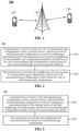
- FIG. 1 shows a communication system 100 applied to the invention.
- the communication system 100 may include a network device 110.
- the network device 110 may be a device in communication with a terminal device 120 (or called a communication terminal or a terminal).
- the network device 110 may provide communication coverage for a specific geographical area, and may communicate with the terminal device located within the coverage.
- FIG. 1 exemplarily illustrates one network device and two terminal devices.
- the communication system 100 may include a plurality of network devices and other number of terminal devices may be included in the coverage of each network device. No limits are made thereto in the embodiments of the present application.
- the communication system 100 may further include other network entities, such as a network controller and a mobile management entity. No limits are made thereto in the embodiments of the present application.
- a device with a communication function in a network/system in the embodiments of the present application may be called a communication device.
- the communication device may include a network device 110 and terminal devices 120 with a communication function.
- the network device 110 and the terminal devices 120 may be specific devices as described above, which will not be elaborated herein.
- the communication device 100 may also include other devices, for example, other network entities, such as a network controller and a mobile management entity. No limits are made thereto in the embodiments of the present application.
- system and “network” herein are often used interchangeably herein.
- network herein is often used interchangeably herein.
- the term “and/or” herein is only an association relationship for describing associated objects and indicates that three relationships may exist. For example, A and/or B may indicate the following three cases: Only A exists, both A and B exist, and only B exists.
- the character “/” herein generally indicates that the contextual objects are in an "or” relationship.
- the "indication" mentioned in the embodiments of the application may be direct indication, or indirect indication, or indicate that there is an association relationship.
- a indicating B may represent that A directly indicates B, for example, B may be acquired through A, or represent that A indirectly indicates B, for example, A indicates C, and B may be acquired through C, or represent that there is an association relationship between A and B.
- correlate can represent that there is a direct or indirect correspondence between the two, or that there is an association between them, or that there is a relationship between indication and being indicated, configuration and being configured, etc.
- the terminal device may also be referred to as User Equipment (UE), an access terminal, a user unit, a user station, a mobile station, a mobile radio station, a remote station, a remote terminal, a mobile device, a user terminal, a terminal, a wireless communication device, a user agent, a user apparatus, or the like.
- UE User Equipment
- the terminal device may be a STATION (ST) in the WLAN, may be a cellular phone, a cordless phone, a Session Initiation Protocol (SIP) phone, a Wireless Local Loop (WLL) station, a Personal Digital Assistant (PDA), a hand-held device having a wireless communication function, a computing device or other processing devices connected to a wireless modem, an on-board vehicle, a wearable device, a terminal device in the next generation communication system, such as a terminal device in an NR network, a terminal device in a Public Land Mobile Network (PLMN) in future evolution, or the like.
- ST STATION
- WLAN may be a cellular phone, a cordless phone, a Session Initiation Protocol (SIP) phone, a Wireless Local Loop (WLL) station, a Personal Digital Assistant (PDA), a hand-held device having a wireless communication function, a computing device or other processing devices connected to a wireless modem, an on-board vehicle, a wearable device,
- the terminal device may also be a wearable device.
- the wearable device also referred to as a wearable intelligent device, is a generic term of wearable devices obtained by performing intelligent designing and development on daily wearing products, such as glasses, gloves, watches, clothes, and shoes, by applying a wearable technology.
- the wearable device is a portable device that is directly put on a human body or is integrated with clothes or ornaments of a user.
- the wearable device is not merely a hardware device, but further implements a powerful function through software support, data exchange, and cloud-based interaction.
- Generalized wearable intelligent devices include, for example, intelligent watches or intelligent glasses with complete functions and large sizes and capable of realizing all or part of functions independent of intelligent phones, and for example, various types of sign monitoring intelligent bands and intelligent j ewelries of which each is dedicated to application functions of a certain type and required to be matched with other devices such as intelligent phones for use.
- the network device may be a device used for communicating with a mobile device.
- the network device may be an Access Point (AP) in WLAN, a Base Transceiver Station (BTS) in GSM or CDMA, or may be a NodeB (NB) in WCDMA, or may also be an Evolutional Node B (eNB or eNodeB) in LTE, or a relay station or an access point, or an on-board device, a wearable device, or a network device or a gNB in an NR network, or a network device in a PLMN network in future evolution, or the like.
- AP Access Point
- BTS Base Transceiver Station
- NB NodeB
- eNB Evolutional Node B
- gNB Evolutional Node B
- the network device may have mobility, for example, the network device may be a mobile device.
- the network device may be a satellite or a balloon station in a Non Terrestrial Network (NTN).
- NTN Non Terrestrial Network
- the satellite may be a Low Earth Orbit (LEO) satellite, a Medium Earth Orbit (MEO) satellite, a Geosynchronous Earth Orbit (GEO) satellite, a High Elliptical Orbit (HEO) satellite, and the like.
- the network device may also be a base station arranged on at the positions, such as land and water.
- the network device provides services for a cell
- the terminal device communicates with the network device through a transmission resource (for example, a frequency-domain resource or a spectrum resource) used by the cell.
- the cell may be a cell corresponding to the network device (for example, a base station).
- the cell may belong to a macro base station, or belong to a base station corresponding to a small cell.
- the small cell may include: a Metro cell, a Micro cell, a Pico cell, a Femto cell, and the like. These small cells have the characteristics of small coverage and low transmission power, and are suitable for providing high-rate data transmission services.
- Measurement mainly refers to mobility measurement in a connected state. After a network issues a measurement configuration to UE, the UE detects a signal quality state of a neighboring cell according to the parameters, such as a Measurement Object and Reporting Configuration, indicated in a measurement configuration, and feeds back measurement report information to the network for handover or improvement of a neighboring cell relationship list by the network device.
- the parameters such as a Measurement Object and Reporting Configuration, indicated in a measurement configuration
- a network device may send measurement configuration information to a terminal device in a connected state through Radio Resource Control (RRC) signaling.
- the terminal device performs measurement according to the content of the measurement configuration information (for example, intra-frequency measurement, inter-frequency measurement, and inter-Radio Access Technologies (RAT) measurement), and then reports a measurement result to the network device.
- the network device may perform configuration of measurement configuration by using RRC connection reconfiguration.
- the measurement configuration information includes following contents.
- each MO indicates a time-frequency position to be measured and a sub-carrier interval of a reference signal.
- a cell related to the MO may also configure a cell offset list, a blacklist cell list, and a whitelist cell list.
- each MO may correspond to a separate Evolved Universal Territorial Radio Access (E-UTRA) frequency point.
- E-UTRA Evolved Universal Territorial Radio Access
- the network device may also configure a cell offset list, a blacklist cell list, and a whitelist cell list.
- the terminal device does not perform any operation on the cells in the blacklist cell list.
- the terminal device performs the event evaluation and the measurement reporting on the cells in the whitelist cell list.
- the network device For each measurement point, the network device configures an SS/PBCH block measurement timing configuration (SMTC) for indicating the time when the terminal device receives a Synchronization Signal Block (SSB) on a neighboring cell corresponding to the measurement frequency point.
- SMTC SS/PBCH block measurement timing configuration
- the SMTC configuration includes an SMTC period, a starting time offset of the SMTC within a period, a duration of the SMTC, etc.
- Each MO corresponds to one or more reporting configurations.
- the reporting configuration may include the following content.
- Reporting criteria that is, a triggering condition in which the terminal device performs measurement reporting, for example, period triggered reporting or event triggered reporting.
- a Reference Signal (SR) type RS of the terminal device used for wave beam and cell measurement, for example, an SS/PBCH block or a Channel State Information Reference Signal (CSI-RS).
- SR Reference Signal
- CSI-RS Channel State Information Reference Signal
- a reporting format a measurement reporting amount (for example, Reference Signal Receiving Power (RSRP)) of the terminal device for each cell and each wave beam.
- RSRP Reference Signal Receiving Power
- other related information may also be included, for example, the maximum number of cells reported by the terminal device and the maximum number of wave beams reported for each cell.
- Measurement events may, for example, include the following events.
- A1 event the signal quality of a serving cell is higher than one threshold.
- A2 event the signal quality of a serving cell is lower than one threshold.
- A3 event the signal quality of a neighboring cell is one threshold higher than the signal quality of a Special Cell (SpCell).
- A4 event the signal quality of a neighboring cell is higher than one threshold.
- A5 event the signal quality of the SpCell is lower than threshold 1, and the signal quality of a neighboring cell is higher than threshold 2.
- A6 event the signal quality of a neighboring cell is one threshold higher than the signal quality of a SCell.
- B1 event the signal quality of an inter-RAT neighboring cell is higher than one threshold.
- PCell Primary Cell
- inter-RAT neighboring cell the signal quality of an inter-RAT neighboring cell is higher than threshold 4.
- Measurement identity is a separate ID, and is used for associating the MO and the reporting configuration.
- one MO is associated with a plurality of reporting configurations simultaneously, or one reporting configuration may also be associated with a plurality of MOs, it can be distinguished through the measurement identity.
- the measurement gap is used for indicating time information that the terminal device performs inter-frequency/inter-RAT measurement. Specifically, the terminal device performs inter-frequency/inter-RAT measurement during a measurement gap.
- the network device may configure a measurement gap configuration per UE for the terminal device or a measurement gap configuration per Frequency Range (FR).
- the network device may configure measurement gap configurations respectively corresponding to FR1 and FR2.
- the FR1 and the FR2 represent different FRs.
- each measurement gap configuration may include at least one of the following:
- Each MO corresponds to one or more reporting configurations.
- the reporting configuration may include the following content.
- Reporting criteria that is, a triggering condition in which the terminal device performs measurement reporting, for example, period triggered reporting or event triggered reporting.
- a triggering event may be several measurement events as described above.
- the measurement gap configuration is configured based on UE, and the SMTC is configured based on a frequency point.
- the coverage radius of a cell is small, and the difference between a signal transmission delay between the UE and a base station of a serving cell and a signal transmission delay between the UE and a base station of a neighboring cell is very small.
- the difference among signal transmission delays between the UE and base stations of different cells may be compensated by configuring the duration of the SMTC, which ensures that the UE receives SSBs of different cells during the duration of the SMTC. Meanwhile, the measurement of the UE on all inter-frequency/inter-RAT frequency points is ensured to be within the measurement gap period by configuring the duration of a measurement gap.
- the maximum configurable value of the duration of the SMTC is 5ms
- the maximum configurable value of the duration of the measurement gap is 6ms.
- the signal transmission delay between UE and a satellite increases greatly.
- SSBs from some cell base stations with great transmission delays may not be received, and the channel quality states of these cell base stations cannot be known, which affects the result of measurement reporting.
- the duration of a gap is prolonged to cover a neighboring cell with a great transmission delay difference within one period, then the serving cell cannot perform data transmission within this period of time, resulting in too long data interruption time and thus affecting the user experience.
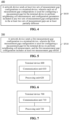
- FIG. 2 illustrates a schematic flowchart of a method 200 for neighboring cell measurement according to an embodiment of the present application. As shown in FIG. 2 , the method 200 includes, but is not limited to, S210 and S220.
- a terminal device receives at least two sets of measurement gap configurations sent by a network device.
- Each set of measurement gap configurations is used for configuring a measurement gap for the terminal device to perform neighboring cell measurement, and configuration parameters included in any two sets of measurement gap configurations in the at least two sets of measurement gaps are at least partially different.
- the terminal device performs the neighboring cell measurement in a measurement gap configured by at least one set of measurement gap configurations of the at least two sets of measurement gap configurations.
- the at least two sets of measurement gap configurations may be configured based on perUE, that is, each UE may be configured with respective at least two sets of measurement gap configurations.
- the terminal device may be configured with at least two sets of measurement gap configurations through high-level signaling.
- the high-level signaling may be RRC signaling.
- the terminal device may perform neighboring cell measurement based on all or part measurement gap configurations of the at least two sets of measurement gap configurations configured by the network device. That is, an RS of a neighboring cell is measured to determine a measurement reporting amount.
- the RS includes, but is not limited to, at least one of the following: an SSB, a CSI-RS, a Demodulation Reference Signal (DMRS), etc.
- an SSB a CSI-RS
- DMRS Demodulation Reference Signal
- the measurement reporting amount may be, for example, Reference Signal Receiving Power (RSRP), Reference Signal Receiving Quality (RSRQ), Signal to Interference plus Noise Ratio (SINR), etc.
- RSRP Reference Signal Receiving Power
- RSS Reference Signal Receiving Quality
- SINR Signal to Interference plus Noise Ratio
- the network device may configure at least two sets of measurement gap configurations for the terminal device.
- each set of measurement gap configurations includes at least one of the following parameters: a period of the measurement gap (mgrp), a starting time offset of the measurement gap within one period (gapOffset), a duration of the measurement gap (mgl), a timing advance of the measurement gap (mgta), and a reference serving cell indicator (refServCellIndicator).
- the configuration parameters in the at least two sets of measurement gap configurations are partially or completely different, such as the gapOffsets are different, the mgls are different, or the mgrps are different.
- starting time offsets in the at least two sets of measurement gap configurations are different.
- Other configuration parameters except the starting time offsets in the at least two sets of measurement gap configurations are the same.
- the operation that the terminal device performs the neighboring cell measurement in the measurement gap configured by at least one set of measurement gap configurations of the at least two sets of measurement gap configurations includes the following operations.
- the terminal device performs the neighboring cell measurement in the measurement gap configured by all measurement gap configurations of the at least two sets of measurement gap configuration; or the terminal device performs the neighboring cell measurement in the measurement gap configured by part measurement gap configurations of the at least two sets of measurement gap configurations.
- the part measurement gap configurations may be indicated by the network device, or may be determined independently by the terminal device. No limits are made thereto in the present application.
- the terminal device may receive first signaling sent by a network device.
- the first signaling is used for activating or deactivating one or more measurement gap configurations of the at least two sets of measurement gap configurations.
- the terminal device performs the neighboring cell measurement according to the currently activated measurement gap configuration.
- the at least two sets of measurement gap configurations include a gap configuration 1, a gap configuration 2, and a gap configuration 3.
- the network device instructs to activate the gap configuration 1 and the gap configuration 2, and then the terminal device may perform neighboring cell measurement based on the gap configuration 1 and the gap configuration 2.
- the network device instructs to deactivate the gap configuration 3, then other gap configurations, i.e., the gap configuration 1 and the gap configuration 2, are activated gap configurations, and then the terminal device may perform the neighboring cell measurement based on the gap configuration 1 and the gap configuration 2.
- the first signaling may be any downlink message or signaling, which is not limited thereto in the present application.
- the first signaling may be a Media Access Control Control Element (MAC CE) or a Physical Downlink Control Channel (PDCCH).
- MAC CE Media Access Control Control Element
- PDCH Physical Downlink Control Channel
- the terminal device may determine the part measurement gap configurations for performing the neighboring cell measurement in the at least two sets of measurement gap configurations according to the signal transmission delay between a neighboring cell of the terminal device and the terminal device.
- the at least two sets of measurement gap configurations include a gap configuration 1, a gap configuration 2, and a gap configuration 3.
- the gap configuration 1 includes gapoffset1, the gap configuration 2 includes gapoffset2, the gap configuration 3 includes gapoffset2, and gapoffset1 ⁇ gapoffset2 ⁇ gapoffset3.
- the terminal device may perform neighboring cell measurement according to the gap configuration 3 for a neighboring cell with a great signal transmission delay, and the terminal device may perform the neighboring cell measurement according to the gap configuration 1 for a neighboring cell with a small signal transmission delay.
- the at least two sets of measurement gap configurations may be applied to neighboring cell measurements within different signal transmission delay ranges.
- neighboring cell measurements with similar transmission delays may be configured to correspond to a set of measurement gap configurations, and neighboring cell measurements within different transmission delay ranges may be configured with different measurement gap configurations.
- the duration of a gap does not need to be prolonged to cover a neighboring cell with a great transmission delay difference within one period, or to cover SMTCs of a plurality of neighboring cells.
- the serving cell cannot perform data transmission during this period of time, resulting in too long data interruption time, and thus affecting the user experience.
- At least two sets of measurement gap configurations used for the neighboring cell measurement within different signal transmission ranges are configured, so that a serving cell may perform data transmission between the gaps configured by different measurement gap configurations, which reduces the continuous occupation duration of the data transmission time of the serving cell by the neighboring cell measurement, and is beneficial to improving the user experience.
- the embodiments of the present application may be applied to any scenario with great signal transmission delays between a neighboring cell and a terminal device and between a serving cell and the terminal device.
- the serving cell of the terminal device is an NTN cell
- the neighboring cell of the terminal device is a terrestrial network cell
- the serving cell of the terminal device is a terrestrial network cell
- the neighboring cell of the terminal device is an NTN cell.
- both the serving cell and the neighboring cell of the terminal device are NTN cells.
- FIG. 3 illustrates a schematic flowchart of a method 300 for neighboring cell measurement according to the invention.
- the method 300 may include, but is not limited to, S310 and S320.
- a terminal device receives a first measurement gap configuration sent by a network device.
- the first measurement gap configuration is used for configuring a measurement gap for the terminal device to perform neighboring cell measurement, and the first measurement gap configuration includes at least two measurement gap offsets.
- the terminal device performs the neighboring cell measurement based on the first measurement gap configuration.
- the first measurement gap configuration may be configured based on perUE, that is, each UE may be configured with the respective first measurement gap configuration including at least two measurement gap offsets.
- the at least two measurement gap offsets are not equal to each other.
- the terminal device may be configured with the first measurement gap configuration through high-level signaling.
- the high-level signaling may be RRC signaling.
- the terminal device may determine time-domain positions of at least two measurement gaps based on the at least two measurement gap offsets in the first measurement gap configuration configured by the network device and other configuration parameters in the first measurement gap configuration, and further may perform the neighboring cell measurement based on the time-domain position(s) of one or more measurement gaps in the time-domain positions of the at least two measurement gaps. That is, an RS of a neighboring cell is measured to determine a measurement reporting amount. Specific implementation of the RS and the measurement reporting amount may refer to the related implementation of the method 200, and will not be elaborated herein.
- the first measurement gap configuration may further include at least one of the following parameters except the at least two measurement gap offsets: a period of the measurement gap (mgrp), a duration of the measurement gap (mgl), a timing advance of the measurement gap (mgta), or a reference serving cell indicator (refServCellIndicator).
- a period of the measurement gap mgrp
- a duration of the measurement gap mgl
- a timing advance of the measurement gap mgta
- refServCellIndicator a reference serving cell indicator
- Each of the at least two measurement gap offsets is an offset relative to a starting time position of said period within a period of one measurement gap. That is, each of the measurement gap offsets is an absolute offset.
- the at least two measurement gap offsets may include gapoffset1, gapoffset2, and gapoffset3.
- the terminal device determines three sets of measurement gap configurations based on these three gapoffsets, i.e., time-domain positions of three measurement gaps.
- the at least two measurement gap offsets include a reference offset and at least one offset adjustment amount.
- the reference offset is an offset relative to a starting time-position of said period within a period of one measurement gap.
- the at least one offset adjustment amount is an offset relative to the reference offset.
- the reference offset is an absolute offset
- the at least one offset adjustment amount is a relative offset, which is relative to the absolute offset.
- a sum of the absolute offset and the offset adjustment amount is a starting time position of the measurement gap within each period may be determined when the time-domain position of each measurement gap is determined.
- the at least two measurement gap offsets may include a reference offset gapoffset_rf and offset adjustment amounts ⁇ offset1 and ⁇ offset2, and then the terminal device determines three gapoffsets, which are respectively gapoffset_rf, gapoffset_rf+ ⁇ offset1, and gapoffset_rf+ ⁇ offset2.
- the terminal device further determines three sets of measurement gap configurations, i.e., time-domain positions of three measurement gaps, based on these three gapoffsets,.
- the terminal device When neighboring cell measurement is performed, the terminal device performs the neighboring cell measurement based on all measurement gap offsets in the at least two measurement gap offsets, or performs the neighboring cell measurement based on part measurement gap offsets in the at least two measurement gap offsets.
- the terminal device determines at least two sets of measurement gap configurations according to all measurement gap offsets in a first measurement gap offset and other configuration parameters in the first measurement gap offset, and may further perform the neighboring cell measurement based on the time-domain positions of the measurement gaps determined by the at least two sets of measurement gap configurations.
- the terminal device determines at least one set of measurement gap configurations according to the part measurement gap offsets in the first measurement gap configuration and other configuration parameters in the first measurement gap configuration, and further performs the neighboring cell measurement based on the time-domain position of the measurement gap determined by the at least one set of measurement gap configurations.
- the part measurement gap offsets may be indicated by the network device, or may be determined independently by the terminal device. No limits are made thereto in the present application.
- the terminal device receives second signaling sent by the network device.
- the second signaling is used for activating or deactivating one or more measurement gap offsets of the at least two sets of measurement gap offsets.
- the terminal device may perform the neighboring cell measurement according to a currently activated measurement gap offset.
- the second signaling may be any downlink message or signaling, which is not limited in the present application.
- the second signaling may be an MAC CE or a PDCCH.
- the at least two measurement gap offsets may include gapoffset1, gapoffset2, and gapoffset3.
- the network device instructs to activate the gapoffset1 and the gapoffset2, and then the terminal device may determine two sets of measurement gap configurations, i.e., time-domain positions of two measurement gaps, based on the gapoffset1 and gapoffset2, and may further perform the neighboring cell measurement at the time-domain positions of the measurement gaps.
- the at least two measurement gap offsets may include gapoffset1, gapoffset2, and gapoffset3.
- the network device instructs to deactivate the gapoffset3, and then other gapoffsets, i.e., the gapoffset1 and the gapoffset2 are activated gapoffsets.
- the terminal device may determine two sets of measurement gap configurations, i.e., the time domain positions of the two measurement gaps, based on the gapoffset1 and the gapoffset2, and further perform the neighboring cell measurement at the time-domain positions of the measurement gaps.
- the terminal device determines a measurement gap offset for performing the neighboring cell measurement in the at least two measurement gap offsets according to a signal transmission delay between a neighboring cell of the terminal device and the terminal device.
- the at least two measurement gap offsets may include gapoffset1, gapoffset2, and gapoffset3, and gapoffset1 ⁇ gapoffset2 ⁇ gapoffset3. Then, the terminal device may perform neighboring cell measurement according to the gapoffset 13 for a neighboring cell with a great signal transmission delay, and perform the neighboring cell measurement according to the gapoffset1 for a neighboring cell with a great signal transmission delay.
- the at least two measurement gap offsets may be applied to neighboring cell measurements within different signal transmission delay ranges.
- neighboring cell measurements with similar transmission delays may be configured to correspond to a measurement gap offset
- neighboring cell measurements within different transmission delay ranges may be configured with different measurement gap offsets.
- the duration of a gap does not need to be prolonged to cover a neighboring cell with a great different transmission delay difference within one period, or to cover SMTCs of a plurality of neighboring cells.
- the serving cell cannot perform data transmission within this period of time, resulting in too long data interruption time and affecting the user experience.
- a serving cell may perform data transmission between the gaps configured based on different measurement gap configurations, which reduces the continuous occupation duration of the data transmission time of the serving cell by the neighboring cell measurement, and is beneficial to improving the user experience.
- the invention may be applied to any scenario with great signal transmission delays between a neighboring cell and a terminal device and between a serving cell and the terminal device.
- the serving cell of the terminal device is an NTN cell
- the neighboring cell of the terminal device is a terrestrial network cell
- the serving cell of the terminal device is a terrestrial network cell
- the neighboring cell of the terminal device is an NTN cell.
- both the serving cell and the neighboring cell of the terminal device are NTN cells.
- FIG. 4 illustrates a schematic flowchart of a method 400 for neighboring cell measurement according to an embodiment of the present application. As shown in FIG. 4 , the method 400 may include, but is not limited to, S410.
- a network device sends at least two sets of measurement gap configurations to a terminal device.
- Each set of measurement gap configurations is used for configuring a measurement gap for the terminal device to perform neighboring cell measurement, and configuration parameters included in any two sets of measurement gap configurations in the at least two sets of measurement gaps are at least partially different.
- the each set of measurement gap configurations includes at least one of the following parameters: a period of the measurement gap, a starting time offset of the measurement gap in one period, a duration of the measurement gap, a timing advance of the measurement gap, or a reference serving cell indicator.
- the starting time offsets of the at least two sets of measurement gap configurations are different.
- Other configuration parameters except the starting time offsets in the at least two sets of measurement gap configurations are the same.
- the method 400 further includes the following operation.
- the network device sends first signaling to the terminal network device.
- the first signaling is used for activating or deactivating one or more sets of measurement gap configurations of the at least two sets of measurement gap configurations.
- the first signaling is an MAC CE or a PDCCH.
- the at least two sets of measurement gap configurations are configured through RRC signaling.
- FIG. 5 illustrates a schematic flowchart of a method 500 for neighboring cell measurement according to the invention.
- the method 500 may include, but is not limited to, S510.
- a network device sends a first measurement gap configuration to a terminal device.
- the first measurement gap configuration is used for configuring a measurement gap for the terminal device to perform neighboring cell measurement, and the first measurement gap configuration includes at least two measurement gap offsets.
- the first measurement gap configuration may further include at least one of the following parameters: a period of the measurement gap, a duration of the measurement gap, a timing advance of the measurement gap, or a reference serving cell indicator.
- each of the at least two measurement gap offsets is an offset relative to the starting time position of said period within a period of one measurement gap; or the at least two measurement gap offsets include a reference offset and at least one offset adjustment amount.
- the reference offset is an offset relative to a starting time position of said period within a period of one measurement gap; and the at least one offset adjustment amount is an offset relative to the reference offset.
- the method 500 further includes the following operation.
- the network device sends second signaling to the terminal device.
- the second signaling is used for activating or deactivating one or more measurement gap offsets of the at least two measurement gap offsets.
- the second signaling is an MAC CE or a PDCCH.
- the first measurement gap configuration is configured through RRC signaling.
- FIG. 6 illustrates a schematic block diagram of a terminal device 600 according to the invention.
- the terminal device 600 includes a communication unit 610 and a processing unit 620.
- the communication unit 610 is configured to receive at least two sets of measurement gap configurations sent by a network device. Each set of measurement gap configurations is used for configuring a measurement gap for the terminal device to perform neighboring cell measurement, and configuration parameters included in any two sets of measurement gap configurations in the at least two sets of measurement gaps are at least partially different.
- the processing unit 620 is configured to perform the neighboring cell measurement in a measurement gap configured by at least one set of measurement gap configurations of the at least two sets of measurement gap configurations.
- the each set of measurement gap configurations may include at least one of the following parameters: a period of the measurement gap, a starting time offset of the measurement gap in one period, a duration of the measurement gap, a timing advance of the measurement gap, or a reference serving cell indicator.
- Starting time offsets in the at least two sets of measurement gap configurations are different.
- Other configuration parameters except the starting time offsets in the at least two sets of measurement gap configurations are the same.
- the processing unit 620 is further configured to: perform the neighboring cell measurement in a measurement gap configured by all measurement gap configurations of the at least two sets of measurement gap configurations; or perform the neighboring cell measurement in a measurement gap configured by part measurement gap configurations of the at least two sets of measurement gap configurations.
- the communication unit 610 is further configured to: receive first signaling sent by the network device.
- the first signaling is used for activating or deactivating one or more measurement gap configurations of the at least two sets of measurement gap configurations.
- the processing unit 620 is further configured to: take A currently activated measurement gap configuration as a measurement gap configuration for performing the neighboring cell measurement.
- the first signaling is an MAC CE or a PDCCH.
- the processing unit 620 is further configured to: determine the part measurement gap configurations for performing the neighboring cell measurement in the at least two sets of measurement gap configurations according to the signal transmission delay between a neighboring cell of the terminal device and the terminal device.
- the at least two sets of measurement gap configurations are configured through RRC signaling.
- the serving cell of the terminal device is an NTN cell
- the neighboring cell of the terminal device is a terrestrial network cell
- the serving cell of the terminal device is a terrestrial network cell
- the neighboring cell of the terminal device is an NTN cell
- both the serving cell and the neighboring cell of the terminal device are NTN cells.
- terminal device 600 may correspond to the terminal device in the invention, and the abovementioned and other operations and/or functions of various units in the terminal device 600 are used to implement the corresponding flows executed by the terminal device in the method shown in FIG. 2 respectively, and will not be elaborated here for simplicity.
- FIG. 7 illustrates a schematic block diagram of a terminal device 700 according to the invention.
- the terminal device 700 includes a communication unit 710 and a processing unit 720.
- the communication unit 710 is configured to receive a first measurement gap configuration sent by a network device.
- the first measurement gap configuration is used for configuring a measurement gap for the terminal device to perform neighboring cell measurement, and the first measurement gap configuration includes at least two measurement gap offsets.
- the processing unit 720 is configured to perform the neighboring cell measurement based on the first measurement gap configuration.
- the first measurement gap configuration may further include at least one of the following parameters: a period of the measurement gap, a duration of the measurement gap, a timing advance of the measurement gap, or a reference serving cell indicator.
- each of the at least two measurement gap offsets are an offset relative to a starting time position of said period within a period of one measurement gap; or the at least two measurement gap offsets include a reference offset and at least one offset adjustment amount.
- the reference offset is an offset relative to a starting time position of said period within a period of one measurement gap; and the at least one offset adjustment amount is an offset relative to the reference offset.
- the processing unit 720 is specifically configured to: perform the neighboring cell measurement based on all measurement gap offsets in the at least two measurement gap offsets; or perform the neighboring cell measurement based on part measurement gap offsets in the at least two measurement gap offsets.
- the processing unit 720 is further configured to: determine at least two sets of measurement gap configurations according to all measurement gap offsets in the first measurement gap configuration and other configuration parameters in the first measurement gap configuration; and perform the neighboring cell measurement based on the at least two sets of measurement gap configurations.
- the processing unit 720 is further configured to: determine at least one set of measurement gap configurations according to the part measurement gap offsets in the first measurement gap configuration and other configuration parameters in the first measurement gap configuration; and perform the neighboring cell measurement based on the at least one set of measurement gap configurations.
- the communication unit 710 is further configured to: receive second signaling sent by the network device.
- the second signaling is used for activating or deactivating one or more measurement gap offsets of the at least two sets of measurement gap offsets.
- the processing unit 720 is further configured to: take a currently activated measurement gap offset as a measurement gap offset for performing the neighboring cell measurement.
- the second signaling is an MAC CE or a PDCCH.
- the processing unit 720 is further configured to: determine a measurement gap offset for performing the neighboring cell measurement in the at least two measurement gap offsets according to a signal transmission delay between a neighboring cell of the terminal device and the terminal device.
- the first measurement gap configuration is configured through RRC signaling.
- the serving cell of the terminal device is an NTN cell
- the neighboring cell of the terminal device is a terrestrial network cell
- the serving cell of the terminal device is a terrestrial network cell
- the neighboring cell of the terminal device is an NTN cell
- both the serving cell and the neighboring cell of the terminal device are NTN cells.
- terminal device 700 may correspond to the terminal device in the invention, and the abovementioned and other operations and/or functions of each unit in the terminal device 700 are used to implement the corresponding flows executed by the terminal device in the method shown in FIG. 3 respectively, and will not be elaborated here for simplicity.
- FIG. 8 illustrates a schematic block diagram of a network device 800 according to the invention. As shown in FIG. 8 , the network device 800 includes a communication unit 810.
- the communication unit 810 is configured to send at least two sets of measurement gap configurations to a terminal device.
- Each set of measurement gap configurations is used for configuring a measurement gap for the terminal device to perform neighboring cell measurement, and configuration parameters included in any two sets of measurement gap configurations in the at least two sets of measurement gaps are at least partially different.
- the each set of measurement gap configurations may include at least one of the following parameters: a period of the measurement gap, a starting time offset of the measurement gap in one period, a duration of the measurement gap, a timing advance of the measurement gap, or a reference serving cell indicator.
- starting time offsets of the at least two sets of measurement gap configurations are different.
- Other configuration parameters except the starting time offsets in the at least two sets of measurement gap configurations are the same.
- the communication unit 810 is further configured to: send first signaling to the terminal device.
- the first signaling is used for activating or deactivating one or more sets of measurement gap configurations of the at least two sets of measurement gap configurations.
- the first signaling is an MAC CE or a PDCCH.
- the at least two sets of measurement gap configurations are configured through RRC.
- the abovementioned communication unit may be a communication interface or a transceiver, or a communication chip, or an input/output interface of a system on chip.
- the abovementioned processing unit may be one or more processors.
- the network device 800 may correspond to the terminal device in the invention, and the abovementioned and other operations and/or functions of each unit in the network device 800 are used to implement the corresponding flows executed by the terminal device in the method shown in FIG. 4 respectively, and will not be elaborated here for simplicity.
- FIG. 9 illustrates a schematic block diagram of a network device 900 according to the invention.
- the network device 900 includes a communication unit 910.
- the communication unit 910 is configured to send a first measurement gap configuration to a terminal device.
- the first measurement gap configuration is used for configuring a measurement gap for the terminal device to perform neighboring cell measurement, and the first measurement gap configuration includes at least two measurement gap offsets.
- the first measurement gap configuration may further include at least one of the following parameters: a period of the measurement gap, a duration of the measurement gap, a timing advance of the measurement gap, or a reference serving cell indicator.
- each of the at least two measurement gap offsets is an offset relative to a starting time position of said period within a period of one measurement gap; or the at least two measurement gap offsets include a reference offset and at least one offset adjustment amount.
- the reference offset is an offset relative to a starting time position of said period within a period of one measurement gap; and the at least one offset adjustment amount is an offset relative to the reference offset.
- the communication unit 910 is further configured to: send second signaling to a terminal device.
- the second signaling is used for activating or deactivating one or more measurement gap offsets of the at least two measurement gap offsets.
- the second signaling is an MAC CE or a PDCCH.
- the first measurement gap configuration is configured through RRC signaling.
- the abovementioned communication unit may be a communication interface or a transceiver, or a communication chip, or an input/output interface of a system on chip.
- the abovementioned processing unit may be one or more processors.
- the network device 900 may correspond to the terminal device in the invention, and the abovementioned and other operations and/or functions of each unit in the network device 900 are used to implement the corresponding flows executed by the terminal device in the method shown in FIG. 5 respectively, and will not be elaborated here for simplicity.
- FIG. 10 illustrates a schematic structural diagram of a communication device 1000 provided by an embodiment of the present application.
- the communication device 1000 as shown in FIG. 10 includes a processor 1010.
- the processor 1010 is configured to call from a memory and run a computer program to implement the methods in the embodiments of the present application.
- the communication device 1000 further includes a memory 1020.
- the processor 1010 is configured to call from the memory 1020 and run the computer program to implement the methods in the embodiments of the present application.
- the memory 1020 may be independent of the processor 1010, or may be integrated into the processor 1010.
- the communication device 1000 may further include a transceiver 1030.
- the processor 1010 may control the transceiver 1030 to be in communication with other devices, specifically, to send information or data to other devices, or receive the information or data sent by other devices.
- the transceiver 1030 may include a transmitter and a receiver.
- the transceiver 1030 may further include an antenna. There may be one or more antennae.
- the communications device 1000 is specifically a network device of the embodiment of the present application, and the communication device 1000 implements corresponding flows implemented by the network device in various methods of the embodiments of the present application, which will not be elaborated here for simplicity.
- the communications device 1000 is specifically a mobile terminal/terminal device of the embodiment of the present application, and the communication device 1000 implements corresponding flows implemented by the mobile terminal/the terminal device in various methods of the embodiments of the present application, which will not be elaborated here for simplicity.
- FIG. 11 illustrates a schematic structural diagram of a chip according to the invention.
- the chip 1100 as shown in FIG. 11 includes a processor 1110.
- the processor 1110 may call from a memory and run a computer program to implement the method in the embodiments of the present application.
- the chip 1100 may further include a memory 1120.
- the processor 1110 may call from the memory 1120 and run the computer program to implement the method in the embodiments of the present application.
- the memory 1120 may be independent of the processor 1110, or may be integrated into the processor 1110.
- the chip 1100 may further include an input interface 1130.
- the processor 1110 may control the input interface 1130 to be in communication with other devices or chips, and specifically to acquire the information or data sent by other devices or chips.
- the chip 1100 may further include an output interface 1140.
- the processor 1110 may control the output interface 1140 to be in communication with other devices or chips, and specifically, to output information or data sent to other devices or chips.
- the chip 1100 may be applied to a network device in the embodiments of the present application, and the chip 1100 may implement corresponding flows implemented by the network device in various methods of the embodiments of the present application, which will not be elaborated here for simplicity.
- the chip 1100 may be applied to a mobile terminal/terminal device in the embodiments of the present application, and the chip 1100 may implement corresponding flows implemented by the mobile terminal/terminal device in various methods of the embodiments of the present application, which will not be elaborated here for simplicity.
- the apparatus mentioned in the embodiments of the present application may also be a chip.
- the apparatus may be a system-level chip, a system chip, a chip system or a system on chip, etc.
- the embodiments of the application further provide a communication system.
- the communication system includes a terminal device and a network device.
- the terminal device may be configured to realize corresponding functions realized by the terminal device in the abovementioned method
- the network device may be configured to realize corresponding functions realized by the network device in the abovementioned method, which will not be elaborated here for simplicity.
- the processor of the embodiments of the present application may be an integrated circuit chip with signal processing capability.
- various steps of the abovementioned method embodiments may be completed by integrated logic circuits of hardware in the processor or instructions in the form of software.
- the abovementioned processor may be a general-purpose processor, a Digital Signal Processor (DSP), an Application Specific Integrated Circuit (ASIC), a Field Programmable Gate Array (FPGA), or other programmable logic devices, discrete gate or transistor logic devices, and discrete hardware components.
- DSP Digital Signal Processor
- ASIC Application Specific Integrated Circuit
- FPGA Field Programmable Gate Array
- the general-purpose processor may be a microprocessor, any conventional processor, or the like.
- Steps of the methods disclosed with reference to the embodiments of the present application may be directly performed and accomplished by a hardware decoding processor, or may be performed and accomplished by a combination of hardware and software modules in the decoding processor.
- the software module may be located in a storage medium mature in the art, such as a random access memory, a flash memory, a read-only memory, a programmable read-only memory or electrically erasable programmable memory, or a register.
- the storage medium is located in the memory, and the processor reads information in the memory and completes the steps in the foregoing methods in combination with hardware of the processor.
- the memory in the embodiments of the present application may be a volatile memory or a nonvolatile memory, or may include a volatile memory and a nonvolatile memory.
- the non-volatile memory may be a Read-Only Memory (ROM), a Programmable ROM (PROM), an Erasable PROM (EPROM), an Electrically EPROM (EEPROM), or a flash memory.
- the volatile memory may be a Random Access Memory (RAM), which is used as an external cache.
- RAMs may be used, for example, a Static RAM (SRAM), a Dynamic RAM (DRAM), a Synchronous DRAM (SDRAM), a Double Data Rate SDRAM (DDR SDRAM), an Enhanced SDRAM (ESDRAM), a Synchlink DRAM (SLDRAM), and a Direct Rambus RAM (DR RAM).
- SRAM Static RAM
- DRAM Dynamic RAM
- SDRAM Synchronous DRAM
- DDR SDRAM Double Data Rate SDRAM
- ESDRAM Enhanced SDRAM
- SLDRAM Synchlink DRAM
- DR RAM Direct Rambus RAM
- the memory in the embodiments of the present application may also be a static RAM (SRAM), a dynamic RAM (DRAM), a synchronous DRAM (SDRAM), a double data rate SDRAM (DDR SDRAM), an enhanced SDRAM (ESDRAM), a synch link DRAM (SLDRAM), and a Direct Rambus RAM (DR RAM).
- SRAM static RAM
- DRAM dynamic RAM
- SDRAM synchronous DRAM
- DDR SDRAM double data rate SDRAM
- ESDRAM enhanced SDRAM
- SLDRAM synch link DRAM
- DR RAM Direct Rambus RAM
- the embodiments of the present application further provide a computer readable storage medium, which is configured to store a computer program.
- the computer readable storage medium may be applied to a network device in the embodiments of the present application.
- the computer program enables a computer to execute corresponding flows implemented by the network device in each method of the embodiments of the present application, which will not be elaborated here for simplicity.
- the computer readable storage medium may be applied to a mobile terminal/terminal device in the embodiments of the present application.
- the computer program enables a computer to execute corresponding flows implemented by the mobile terminal/terminal device in each method of the embodiments of the present application, which will not be elaborated here for simplicity.
- the embodiments of the application further provide a computer program product, which includes a computer program instruction.
- the computer program product may be applied to a network device in the embodiments of the present application.
- the computer program instruction enables a computer to execute corresponding flows implemented by the network device in each method of the embodiments of the present application, which will not be elaborated here for simplicity.
- the computer program product may be applied to a mobile terminal/terminal device in the embodiments of the present application.
- the computer program instruction enables a computer to execute corresponding flows implemented by the mobile terminal/terminal device in each method of the embodiments of the present application, which will not be elaborated here for simplicity.
- the embodiments of the application further provide a computer program.
- the computer program may be applied to a network device in the embodiments of the present application.
- the computer program runs in a computer to enable the computer to execute corresponding flows implemented by the network device in each method of the embodiments of the present application, which will not be elaborated here for simplicity.
- the computer program may be applied to a mobile terminal/terminal device in the embodiments of the present application.
- the computer program when running on a computer, enables the computer to execute corresponding flows implemented by the mobile terminal/terminal device in each method of the embodiments of the present application, which will not be elaborated here for simplicity.
- the disclosed system, apparatus, and method may be implemented in other manners.
- the described apparatus embodiments are merely schematic.
- the unit division is merely logical function division and may be other division in actual implementation.
- a plurality of units or components may be combined or integrated into another system, or some features may be ignored or may not be performed.
- the displayed or discussed mutual couplings or direct couplings or communication connections may be implemented by using some interfaces.
- the indirect couplings or communication connections between the apparatuses or units may be implemented in electronic, mechanical, or other forms.
- the units described as separate parts may or may not be physically separate, and parts displayed as units may or may not be physical units, may be located in one location, or may be distributed on a plurality of network elements. Some or all of the units may be selected based on actual requirements to achieve the objectives of the solutions of the embodiments.
- functional units in the embodiments of the present application may be integrated into one processing unit, or each of the units may exist alone physically, or two or more units are integrated into one unit.
- the software product is stored in a storage medium, and includes several instructions for instructing a computer device (which may be a personal computer, a server, a network device, or the like) to perform all or some of the steps of the methods described in the embodiments of the present application.
- the foregoing storage medium includes: various media capable of storing program codes, such as a USB flash disc, a mobile hard disc, a Read-Only Memory (ROM), a Random Access Memory (RAM), a magnetic disc, or a compact disc.
Landscapes
- Engineering & Computer Science (AREA)
- Computer Networks & Wireless Communication (AREA)
- Signal Processing (AREA)
- Mobile Radio Communication Systems (AREA)
Claims (12)
- Verfahren zur Nachbarzellenmessung, wobei das Verfahren Folgendes umfasst:Empfangen (S210) mindestens zweier Sätze von Messspaltkonfigurationen, die von einem Netzwerkgerät gesendet werden, durch ein Endgerät, wobei jeder Satz von Messspaltkonfigurationen zum Konfigurieren eines Messspalts für das Endgerät verwendet wird, um eine Nachbarzellenmessung durchzuführen, und mindestens einen der folgenden Parameter umfasst: eine Periode des Messspalts, die mit Hilfe jedes Satzes von Messspaltkonfigurationen konfiguriert wird, einen Startzeitversatz des Messspaltes in einer Periode, eine Dauer des Messspalts, einen zeitlichen Fortschritt des Messspalts oder einen Referenzindikator einer bedienenden Zelle, und Konfigurationsparameter, die in beliebigen zwei Sätzen von Messspaltkonfigurationen in den mindestens zwei Sätzen von Messspaltkonfigurationen enthalten sind, zumindest teilweise verschieden sind, wobei Startzeitversätze in den mindestens zwei Sätzen von Messspaltkonfigurationen verschieden sind und weitere Konfigurationsparameter mit Ausnahme der Startzeitversätze in den mindestens zwei Sätzen von Messspaltkonfigurationen gleich sind, undDurchführen (S220) der Nachbarzellenmessung durch das Endgerät in einem Messspalt, der durch mindestens einen Satz von Messspaltkonfigurationen der mindestens zwei Sätze von Messspaltkonfigurationen konfiguriert ist.
- Verfahren nach Anspruch 1, wobei das Durchführen (S220) der Nachbarzellenmessung durch das Endgerät in einem Messspalt, der durch mindestens einen Satz von Messspaltkonfigurationen der mindestens zwei Sätze von Messspaltkonfigurationen konfiguriert ist, Folgendes umfasst:Durchführen der Nachbarzellenmessung durch das Endgerät in einem Messspalt, der durch alle Messspaltkonfigurationen der mindestens zwei Sätze von Messspaltkonfigurationen konfiguriert wird, oderDurchführen der Nachbarzellenmessung durch das Endgerät in einem Messspalt, der durch einen Teil der Messspaltkonfigurationen der mindestens zwei Sätze von Messspaltkonfigurationen konfiguriert ist.
- Verfahren nach Anspruch 2, ferner Folgendes umfassend:Empfangen erster Signalisierung, die von dem Netzwerkgerät gesendet wird, durch das Endgerät, wobei die erste Signalisierung verwendet wird, um eine oder mehrere Messspaltkonfigurationen der mindestens zwei Sätze von Messspaltkonfigurationen zu aktivieren oder zu deaktivieren, undNehmen einer aktuell aktivierten Messspaltkonfiguration als Messspaltkonfiguration zum Durchführen der Nachbarzellenmessung,wobei die erste Signalisierung ein MAC-, Media-Access-Control-, Steuerelement, CE, oder ein PDCCH, Physical Downlink Control Channel, ist.
- Verfahren nach Anspruch 2, ferner Folgendes umfassend:
Bestimmen des Teils der Messspaltkonfigurationen durch das Endgerät zum Durchführen der Nachbarzellenmessung in den mindestens zwei Sätzen von Messspaltkonfigurationen gemäß einer Signalübertragungsverzögerung zwischen einer Nachbarzelle des Endgeräts und dem Endgerät. - Verfahren nach einem der Ansprüche 1 bis 4, wobei die mindestens zwei Sätze von Messspaltkonfigurationen durch eine RRC-, Radio-Ressource-Control-, Signalisierung konfiguriert werden.
- Verfahren nach einem der Ansprüche 1 bis 5, wobei eine bedienende Zelle des Endgeräts eine NTN-, Non-Terrestrial-Network-, Zelle ist und eine Nachbarzelle des Endgeräts eine Zelle eines terrestrischen Netzwerks ist oderdie bedienende Zelle des Endgeräts eine Zelle eines terrestrischen Netzwerks ist und die Nachbarzelle des Endgeräts eine NTN-Zelle ist odersowohl die bedienende Zelle als auch die Nachbarzelle des Endgeräts NTN-Zellen sind.
- Verfahren zur Nachbarzellenmessung, wobei das Verfahren Folgendes umfasst:
Senden (S410) mindestens zweier Sätze von Messspaltkonfigurationen an ein Endgerät durch ein Netzwerkgerät, wobei jeder Satz von Messspaltkonfigurationen zum Konfigurieren eines Messspalts für das Endgerät verwendet wird, um eine Nachbarzellenmessung durchzuführen, und mindestens einen der folgenden Parameter umfasst: eine Periode des Messspalts, die mit Hilfe jedes Satzes von Messspaltkonfigurationen konfiguriert wird, einen Startzeitversatz des Messspaltes in einer Periode, eine Dauer des Messspalts, einen zeitlichen Fortschritt des Messspalts oder einen Referenzindikator einer bedienenden Zelle, und Konfigurationsparameter, die in beliebigen zwei Sätzen von Messspaltkonfigurationen in den mindestens zwei Sätzen von Messspaltkonfigurationen enthalten sind, zumindest teilweise verschieden sind, wobei Startzeitversätze in den mindestens zwei Sätzen von Messspaltkonfigurationen verschieden sind und weitere Konfigurationsparameter mit Ausnahme der Startzeitversätze in den mindestens zwei Sätzen Messspaltkonfigurationen gleich sind. - Verfahren nach Anspruch 7, ferner Folgendes umfassend:Senden erster Signalisierung an das End-Netzwerk-Gerät durch das Netzwerkgerät, wobei die erste Signalisierung verwendet wird, um eine oder mehrere Messspaltkonfigurationen der mindestens zwei Sätze von Messspaltkonfigurationen zu aktivieren oder zu deaktivieren,wobei die erste Signalisierung ein MAC-, Media-Access-Control-, Steuerelement, CE, oder ein PDCCH, Physical Downlink Control Channel, ist.
- Verfahren nach Anspruch 7 oder 8, wobei die mindestens zwei Sätze End-Netzwerk-Gerät Messspaltkonfigurationen durch eine RRC-, Radio-Ressource-Control-, Signalisierung konfiguriert werden.
- Endgerät, einen Prozessor (1010) und einen Speicher (1020) umfassend, wobei der Speicher (1020) dafür konfiguriert ist, ein Computerprogramm zu speichern, und der Prozessor (1010) dafür konfiguriert ist, das in dem Speicher gespeicherte Computerprogramm aufzurufen und abzuarbeiten, um das Verfahren nach einem der Ansprüche 1 bis 6 durchzuführen.
- Netzwerkgerät, einen Prozessor (1010) und einen Speicher (1020) umfassend, wobei der Speicher (1020) dafür konfiguriert ist, ein Computerprogramm zu speichern und der Prozessor (1010) dafür konfiguriert ist, das in dem Speicher gespeicherte Computerprogramm aufzurufen und abzuarbeiten, um das Verfahren nach einem der Ansprüche 7 bis 9 durchzuführen.
- Computerlesbares Speichermedium, dafür konfiguriert, ein Computerprogramm zu speichern, wobei das Computerprogramm einen Computer in die Lage versetzt, das Verfahren nach einem der Ansprüche 1 bis 6 auszuführen oder das Verfahren nach einem der Ansprüche 7 bis 9 auszuführen.
Applications Claiming Priority (1)
| Application Number | Priority Date | Filing Date | Title |
|---|---|---|---|
| PCT/CN2020/107531 WO2022027489A1 (zh) | 2020-08-06 | 2020-08-06 | 邻区测量的方法、终端设备和网络设备 |
Publications (3)
| Publication Number | Publication Date |
|---|---|
| EP4156761A1 EP4156761A1 (de) | 2023-03-29 |
| EP4156761A4 EP4156761A4 (de) | 2023-07-12 |
| EP4156761B1 true EP4156761B1 (de) | 2024-11-06 |
Family
ID=80118616
Family Applications (1)
| Application Number | Title | Priority Date | Filing Date |
|---|---|---|---|
| EP20948846.9A Active EP4156761B1 (de) | 2020-08-06 | 2020-08-06 | Verfahren zur nachbarzellenmessung, endgerätevorrichtung und netzwerkvorrichtung |
Country Status (4)
| Country | Link |
|---|---|
| US (1) | US20230115662A1 (de) |
| EP (1) | EP4156761B1 (de) |
| CN (2) | CN115606231A (de) |
| WO (2) | WO2022027489A1 (de) |
Families Citing this family (4)
| Publication number | Priority date | Publication date | Assignee | Title |
|---|---|---|---|---|
| US20220132565A1 (en) * | 2020-10-22 | 2022-04-28 | Qualcomm Incorporated | Measurement times for radio resource management |
| CN116897560A (zh) * | 2022-02-11 | 2023-10-17 | 北京小米移动软件有限公司 | 一种信息配置方法/装置/设备及存储介质 |
| CN117641422A (zh) * | 2022-08-09 | 2024-03-01 | 华为技术有限公司 | 一种通信方法及通信装置 |
| EP4666644A1 (de) * | 2023-02-16 | 2025-12-24 | Telefonaktiebolaget LM Ericsson (publ) | Aktivierung von messlücken für ntn |
Citations (1)
| Publication number | Priority date | Publication date | Assignee | Title |
|---|---|---|---|---|
| WO2020015563A1 (zh) * | 2018-07-19 | 2020-01-23 | 维沃移动通信有限公司 | 用于测量配置的方法、用户设备、网络设备、及存储介质 |
Family Cites Families (16)
| Publication number | Priority date | Publication date | Assignee | Title |
|---|---|---|---|---|
| CN102065452B (zh) * | 2009-11-12 | 2015-08-12 | 中兴通讯股份有限公司 | 系统间测量方法、装置和系统 |
| US9119036B2 (en) * | 2010-05-10 | 2015-08-25 | Telefonaktiebolaget L M Ericsson (Publ) | Enhanced measurement gap configuration support for positioning |
| CN103037399B (zh) * | 2011-09-30 | 2017-10-03 | 中兴通讯股份有限公司 | 一种异频测量配置方法及装置 |
| CN104247493B (zh) * | 2013-04-03 | 2018-05-11 | 华为技术有限公司 | 一种进行异频小区测量的方法及装置 |
| CN116156527A (zh) * | 2017-05-11 | 2023-05-23 | 展讯通信(上海)有限公司 | 双连接下异频邻区的测量方法及系统 |
| CN117834365A (zh) * | 2017-05-12 | 2024-04-05 | 苹果公司 | 用于下一代无线电(nr)和长期演进(lte)的测量设计 |
| EP3666009B1 (de) * | 2017-08-10 | 2023-11-29 | Apple Inc. | Verfahren und anordnungen zur messspaltkonfiguration |
| US10117139B1 (en) * | 2017-09-19 | 2018-10-30 | Qualcomm Incorporated | Techniques and apparatuses for improved neighbor selection in 5G cellular systems |
| EP3487206A1 (de) * | 2017-11-15 | 2019-05-22 | Fujitsu Limited | Messspaltkonfiguration für 5g |
| CN109803303B (zh) * | 2017-11-16 | 2022-10-04 | 中国移动通信有限公司研究院 | 一种频点测量方法、测量配置方法、终端及基站 |
| US10932147B2 (en) * | 2018-03-30 | 2021-02-23 | Mediatek Inc. | Gap-based cell measurement in wireless communication system |
| WO2020082211A1 (en) * | 2018-10-22 | 2020-04-30 | Qualcomm Incorporated | On-demand measurement gap for inter-frequency rrm measurements |
| WO2020092732A1 (en) * | 2018-11-01 | 2020-05-07 | Intel Corporation | Measurements in rrc_idle state in new radio (nr) systems |
| CN111491378B (zh) * | 2019-01-29 | 2024-02-02 | 华为技术有限公司 | 用于传输下行控制信道的方法、终端设备和网络设备 |
| EP4054235A4 (de) * | 2019-11-01 | 2022-11-16 | Guangdong Oppo Mobile Telecommunications Corp., Ltd. | Verfahren und vorrichtung zur messung von zellen sowie vorrichtung und speichermedium |
| JP7695274B2 (ja) * | 2020-06-30 | 2025-06-18 | クゥアルコム・インコーポレイテッド | 測定ギャップの動的構成 |
-
2020
- 2020-08-06 EP EP20948846.9A patent/EP4156761B1/de active Active
- 2020-08-06 WO PCT/CN2020/107531 patent/WO2022027489A1/zh not_active Ceased
- 2020-08-06 CN CN202080100975.5A patent/CN115606231A/zh active Pending
- 2020-09-30 CN CN202080102095.1A patent/CN115804139B/zh active Active
- 2020-09-30 WO PCT/CN2020/119676 patent/WO2022027811A1/zh not_active Ceased
-
2022
- 2022-12-13 US US18/065,414 patent/US20230115662A1/en active Pending
Patent Citations (1)
| Publication number | Priority date | Publication date | Assignee | Title |
|---|---|---|---|---|
| WO2020015563A1 (zh) * | 2018-07-19 | 2020-01-23 | 维沃移动通信有限公司 | 用于测量配置的方法、用户设备、网络设备、及存储介质 |
Non-Patent Citations (1)
| Title |
|---|
| "3rd Generation Partnership Project; Technical Specification Group Radio Access Network; NR; Radio Resource Control (RRC) protocol specification (Release 16)", 24 July 2020 (2020-07-24), XP052353422, Retrieved from the Internet <URL:https://ftp.3gpp.org/tsg_ran/WG2_RL2/Specifications/202007_final_specs_after_RAN_88/38331-g10.zip 38331-g10.docx> [retrieved on 20200724] * |
Also Published As
| Publication number | Publication date |
|---|---|
| US20230115662A1 (en) | 2023-04-13 |
| WO2022027489A1 (zh) | 2022-02-10 |
| CN115804139B (zh) | 2025-02-11 |
| CN115606231A (zh) | 2023-01-13 |
| WO2022027811A1 (zh) | 2022-02-10 |
| EP4156761A1 (de) | 2023-03-29 |
| EP4156761A4 (de) | 2023-07-12 |
| CN115804139A (zh) | 2023-03-14 |
Similar Documents
| Publication | Publication Date | Title |
|---|---|---|
| US12010636B2 (en) | Wireless communication method, terminal device, and network device | |
| EP3890391B1 (de) | Verfahren und vorrichtung für rrm-messung | |
| US20230115662A1 (en) | Method for neighboring cell measurement, terminal device and network device | |
| EP3883317B1 (de) | Drahtloskommunikationsverfahren, endgerätevorrichtung und netzwerkvorrichtung | |
| US12028771B2 (en) | Wireless communication method, terminal device and network device | |
| EP4221329B1 (de) | Drahtloskommunikationsverfahren, endgerätevorrichtung und netzwerkvorrichtung | |
| WO2020186532A1 (zh) | 无线通信方法、终端设备和网络设备 | |
| CN116566567A (zh) | 一种测量方法及装置、终端设备、网络设备 | |
| JP2023500178A (ja) | 無線通信方法、端末デバイス及びネットワークデバイス | |
| CN116017540B (zh) | 小区测量的方法和终端设备 | |
| US12483940B2 (en) | Wireless communication method and terminal device | |
| WO2021003624A1 (zh) | Bwp切换方法和终端设备 | |
| US20230413147A1 (en) | Method for determining frequency point and terminal device | |
| CN118044248A (zh) | 无线通信的方法、终端设备和网络设备 | |
| CN116438839A (zh) | 一种测量间隔的配置方法及装置、终端设备、网络设备 | |
| CN111357251A (zh) | 一种信号传输的方法、装置及计算机存储介质 | |
| EP4080959B1 (de) | Schaltverfahren, endgerät, netzwerkgerät und kommunikationssystem | |
| CN116438828A (zh) | 测量配置方法、终端设备、网络设备、芯片和存储介质 | |
| CN115245014B (zh) | 工作带宽部分的切换方法、终端设备和网络设备 | |
| CN115428349B (zh) | 信号测量的方法、终端设备和网络设备 | |
| WO2023141872A1 (zh) | 无线通信的方法、终端设备和网络设备 | |
| WO2019242681A1 (zh) | 无线链路监测的方法和终端设备 | |
| WO2023102914A1 (zh) | 无线通信的方法、终端设备和网络设备 | |
| CN118056430A (zh) | 无线通信的方法、终端设备和网络设备 |
Legal Events
| Date | Code | Title | Description |
|---|---|---|---|
| STAA | Information on the status of an ep patent application or granted ep patent |
Free format text: STATUS: THE INTERNATIONAL PUBLICATION HAS BEEN MADE |
|
| PUAI | Public reference made under article 153(3) epc to a published international application that has entered the european phase |
Free format text: ORIGINAL CODE: 0009012 |
|
| STAA | Information on the status of an ep patent application or granted ep patent |
Free format text: STATUS: REQUEST FOR EXAMINATION WAS MADE |
|
| 17P | Request for examination filed |
Effective date: 20221223 |
|
| AK | Designated contracting states |
Kind code of ref document: A1 Designated state(s): AL AT BE BG CH CY CZ DE DK EE ES FI FR GB GR HR HU IE IS IT LI LT LU LV MC MK MT NL NO PL PT RO RS SE SI SK SM TR |
|
| A4 | Supplementary search report drawn up and despatched |
Effective date: 20230609 |
|
| RIC1 | Information provided on ipc code assigned before grant |
Ipc: H04W 36/00 20090101ALN20230602BHEP Ipc: H04W 24/10 20090101AFI20230602BHEP |
|
| DAV | Request for validation of the european patent (deleted) | ||
| DAX | Request for extension of the european patent (deleted) | ||
| STAA | Information on the status of an ep patent application or granted ep patent |
Free format text: STATUS: EXAMINATION IS IN PROGRESS |
|
| 17Q | First examination report despatched |
Effective date: 20240221 |
|
| GRAP | Despatch of communication of intention to grant a patent |
Free format text: ORIGINAL CODE: EPIDOSNIGR1 |
|
| STAA | Information on the status of an ep patent application or granted ep patent |
Free format text: STATUS: GRANT OF PATENT IS INTENDED |
|
| RIC1 | Information provided on ipc code assigned before grant |
Ipc: H04W 36/00 20090101ALN20240704BHEP Ipc: H04W 24/10 20090101AFI20240704BHEP |
|
| RIC1 | Information provided on ipc code assigned before grant |
Ipc: H04W 36/00 20090101ALN20240710BHEP Ipc: H04W 24/10 20090101AFI20240710BHEP |
|
| INTG | Intention to grant announced |
Effective date: 20240722 |
|
| RIC1 | Information provided on ipc code assigned before grant |
Ipc: H04W 36/00 20090101ALN20240712BHEP Ipc: H04W 24/10 20090101AFI20240712BHEP |
|
| GRAS | Grant fee paid |
Free format text: ORIGINAL CODE: EPIDOSNIGR3 |
|
| GRAA | (expected) grant |
Free format text: ORIGINAL CODE: 0009210 |
|
| STAA | Information on the status of an ep patent application or granted ep patent |
Free format text: STATUS: THE PATENT HAS BEEN GRANTED |
|
| AK | Designated contracting states |
Kind code of ref document: B1 Designated state(s): AL AT BE BG CH CY CZ DE DK EE ES FI FR GB GR HR HU IE IS IT LI LT LU LV MC MK MT NL NO PL PT RO RS SE SI SK SM TR |
|
| REG | Reference to a national code |
Ref country code: GB Ref legal event code: FG4D |
|
| REG | Reference to a national code |
Ref country code: CH Ref legal event code: EP |
|
| REG | Reference to a national code |
Ref country code: DE Ref legal event code: R096 Ref document number: 602020041124 Country of ref document: DE |
|
| REG | Reference to a national code |
Ref country code: IE Ref legal event code: FG4D |
|
| REG | Reference to a national code |
Ref country code: LT Ref legal event code: MG9D |
|
| REG | Reference to a national code |
Ref country code: NL Ref legal event code: MP Effective date: 20241106 |
|
| P01 | Opt-out of the competence of the unified patent court (upc) registered |
Free format text: CASE NUMBER: APP_9919/2025 Effective date: 20250226 |
|
| PG25 | Lapsed in a contracting state [announced via postgrant information from national office to epo] |
Ref country code: IS Free format text: LAPSE BECAUSE OF FAILURE TO SUBMIT A TRANSLATION OF THE DESCRIPTION OR TO PAY THE FEE WITHIN THE PRESCRIBED TIME-LIMIT Effective date: 20250306 Ref country code: HR Free format text: LAPSE BECAUSE OF FAILURE TO SUBMIT A TRANSLATION OF THE DESCRIPTION OR TO PAY THE FEE WITHIN THE PRESCRIBED TIME-LIMIT Effective date: 20241106 Ref country code: PT Free format text: LAPSE BECAUSE OF FAILURE TO SUBMIT A TRANSLATION OF THE DESCRIPTION OR TO PAY THE FEE WITHIN THE PRESCRIBED TIME-LIMIT Effective date: 20250306 |
|
| PG25 | Lapsed in a contracting state [announced via postgrant information from national office to epo] |
Ref country code: FI Free format text: LAPSE BECAUSE OF FAILURE TO SUBMIT A TRANSLATION OF THE DESCRIPTION OR TO PAY THE FEE WITHIN THE PRESCRIBED TIME-LIMIT Effective date: 20241106 Ref country code: NL Free format text: LAPSE BECAUSE OF FAILURE TO SUBMIT A TRANSLATION OF THE DESCRIPTION OR TO PAY THE FEE WITHIN THE PRESCRIBED TIME-LIMIT Effective date: 20241106 |
|
| REG | Reference to a national code |
Ref country code: AT Ref legal event code: MK05 Ref document number: 1740750 Country of ref document: AT Kind code of ref document: T Effective date: 20241106 |
|
| PG25 | Lapsed in a contracting state [announced via postgrant information from national office to epo] |
Ref country code: BG Free format text: LAPSE BECAUSE OF FAILURE TO SUBMIT A TRANSLATION OF THE DESCRIPTION OR TO PAY THE FEE WITHIN THE PRESCRIBED TIME-LIMIT Effective date: 20241106 |
|
| PG25 | Lapsed in a contracting state [announced via postgrant information from national office to epo] |
Ref country code: ES Free format text: LAPSE BECAUSE OF FAILURE TO SUBMIT A TRANSLATION OF THE DESCRIPTION OR TO PAY THE FEE WITHIN THE PRESCRIBED TIME-LIMIT Effective date: 20241106 |
|
| PG25 | Lapsed in a contracting state [announced via postgrant information from national office to epo] |
Ref country code: NO Free format text: LAPSE BECAUSE OF FAILURE TO SUBMIT A TRANSLATION OF THE DESCRIPTION OR TO PAY THE FEE WITHIN THE PRESCRIBED TIME-LIMIT Effective date: 20250206 |
|
| PG25 | Lapsed in a contracting state [announced via postgrant information from national office to epo] |
Ref country code: LV Free format text: LAPSE BECAUSE OF FAILURE TO SUBMIT A TRANSLATION OF THE DESCRIPTION OR TO PAY THE FEE WITHIN THE PRESCRIBED TIME-LIMIT Effective date: 20241106 Ref country code: GR Free format text: LAPSE BECAUSE OF FAILURE TO SUBMIT A TRANSLATION OF THE DESCRIPTION OR TO PAY THE FEE WITHIN THE PRESCRIBED TIME-LIMIT Effective date: 20250207 Ref country code: AT Free format text: LAPSE BECAUSE OF FAILURE TO SUBMIT A TRANSLATION OF THE DESCRIPTION OR TO PAY THE FEE WITHIN THE PRESCRIBED TIME-LIMIT Effective date: 20241106 |
|
| PG25 | Lapsed in a contracting state [announced via postgrant information from national office to epo] |
Ref country code: PL Free format text: LAPSE BECAUSE OF FAILURE TO SUBMIT A TRANSLATION OF THE DESCRIPTION OR TO PAY THE FEE WITHIN THE PRESCRIBED TIME-LIMIT Effective date: 20241106 |
|
| PG25 | Lapsed in a contracting state [announced via postgrant information from national office to epo] |
Ref country code: RS Free format text: LAPSE BECAUSE OF FAILURE TO SUBMIT A TRANSLATION OF THE DESCRIPTION OR TO PAY THE FEE WITHIN THE PRESCRIBED TIME-LIMIT Effective date: 20250206 |
|
| PG25 | Lapsed in a contracting state [announced via postgrant information from national office to epo] |
Ref country code: SM Free format text: LAPSE BECAUSE OF FAILURE TO SUBMIT A TRANSLATION OF THE DESCRIPTION OR TO PAY THE FEE WITHIN THE PRESCRIBED TIME-LIMIT Effective date: 20241106 |
|
| PG25 | Lapsed in a contracting state [announced via postgrant information from national office to epo] |
Ref country code: DK Free format text: LAPSE BECAUSE OF FAILURE TO SUBMIT A TRANSLATION OF THE DESCRIPTION OR TO PAY THE FEE WITHIN THE PRESCRIBED TIME-LIMIT Effective date: 20241106 |
|
| PG25 | Lapsed in a contracting state [announced via postgrant information from national office to epo] |
Ref country code: EE Free format text: LAPSE BECAUSE OF FAILURE TO SUBMIT A TRANSLATION OF THE DESCRIPTION OR TO PAY THE FEE WITHIN THE PRESCRIBED TIME-LIMIT Effective date: 20241106 |
|
| PG25 | Lapsed in a contracting state [announced via postgrant information from national office to epo] |
Ref country code: RO Free format text: LAPSE BECAUSE OF FAILURE TO SUBMIT A TRANSLATION OF THE DESCRIPTION OR TO PAY THE FEE WITHIN THE PRESCRIBED TIME-LIMIT Effective date: 20241106 |
|
| PG25 | Lapsed in a contracting state [announced via postgrant information from national office to epo] |
Ref country code: SK Free format text: LAPSE BECAUSE OF FAILURE TO SUBMIT A TRANSLATION OF THE DESCRIPTION OR TO PAY THE FEE WITHIN THE PRESCRIBED TIME-LIMIT Effective date: 20241106 |
|
| PG25 | Lapsed in a contracting state [announced via postgrant information from national office to epo] |
Ref country code: CZ Free format text: LAPSE BECAUSE OF FAILURE TO SUBMIT A TRANSLATION OF THE DESCRIPTION OR TO PAY THE FEE WITHIN THE PRESCRIBED TIME-LIMIT Effective date: 20241106 |
|
| PG25 | Lapsed in a contracting state [announced via postgrant information from national office to epo] |
Ref country code: IT Free format text: LAPSE BECAUSE OF FAILURE TO SUBMIT A TRANSLATION OF THE DESCRIPTION OR TO PAY THE FEE WITHIN THE PRESCRIBED TIME-LIMIT Effective date: 20241106 |
|
| REG | Reference to a national code |
Ref country code: DE Ref legal event code: R097 Ref document number: 602020041124 Country of ref document: DE |
|
| PG25 | Lapsed in a contracting state [announced via postgrant information from national office to epo] |
Ref country code: SE Free format text: LAPSE BECAUSE OF FAILURE TO SUBMIT A TRANSLATION OF THE DESCRIPTION OR TO PAY THE FEE WITHIN THE PRESCRIBED TIME-LIMIT Effective date: 20241106 |
|
| PLBE | No opposition filed within time limit |
Free format text: ORIGINAL CODE: 0009261 |
|
| STAA | Information on the status of an ep patent application or granted ep patent |
Free format text: STATUS: NO OPPOSITION FILED WITHIN TIME LIMIT |
|
| PGFP | Annual fee paid to national office [announced via postgrant information from national office to epo] |
Ref country code: DE Payment date: 20250827 Year of fee payment: 6 |
|
| 26N | No opposition filed |
Effective date: 20250807 |
|
| PGFP | Annual fee paid to national office [announced via postgrant information from national office to epo] |
Ref country code: GB Payment date: 20250826 Year of fee payment: 6 |