EP4156357A2 - Manufacturing method for secondary battery and secondary battery - Google Patents
Manufacturing method for secondary battery and secondary battery Download PDFInfo
- Publication number
- EP4156357A2 EP4156357A2 EP22196306.9A EP22196306A EP4156357A2 EP 4156357 A2 EP4156357 A2 EP 4156357A2 EP 22196306 A EP22196306 A EP 22196306A EP 4156357 A2 EP4156357 A2 EP 4156357A2
- Authority
- EP
- European Patent Office
- Prior art keywords
- shape
- sealing plate
- terminal
- oval
- caulking
- Prior art date
- Legal status (The legal status is an assumption and is not a legal conclusion. Google has not performed a legal analysis and makes no representation as to the accuracy of the status listed.)
- Granted
Links
Images


Classifications
-
- H—ELECTRICITY
- H01—ELECTRIC ELEMENTS
- H01M—PROCESSES OR MEANS, e.g. BATTERIES, FOR THE DIRECT CONVERSION OF CHEMICAL ENERGY INTO ELECTRICAL ENERGY
- H01M50/00—Constructional details or processes of manufacture of the non-active parts of electrochemical cells other than fuel cells, e.g. hybrid cells
- H01M50/10—Primary casings; Jackets or wrappings
- H01M50/102—Primary casings; Jackets or wrappings characterised by their shape or physical structure
- H01M50/103—Primary casings; Jackets or wrappings characterised by their shape or physical structure prismatic or rectangular
-
- H—ELECTRICITY
- H01—ELECTRIC ELEMENTS
- H01M—PROCESSES OR MEANS, e.g. BATTERIES, FOR THE DIRECT CONVERSION OF CHEMICAL ENERGY INTO ELECTRICAL ENERGY
- H01M50/00—Constructional details or processes of manufacture of the non-active parts of electrochemical cells other than fuel cells, e.g. hybrid cells
- H01M50/50—Current conducting connections for cells or batteries
- H01M50/543—Terminals
- H01M50/564—Terminals characterised by their manufacturing process
-
- H—ELECTRICITY
- H01—ELECTRIC ELEMENTS
- H01M—PROCESSES OR MEANS, e.g. BATTERIES, FOR THE DIRECT CONVERSION OF CHEMICAL ENERGY INTO ELECTRICAL ENERGY
- H01M10/00—Secondary cells; Manufacture thereof
- H01M10/04—Construction or manufacture in general
-
- H—ELECTRICITY
- H01—ELECTRIC ELEMENTS
- H01M—PROCESSES OR MEANS, e.g. BATTERIES, FOR THE DIRECT CONVERSION OF CHEMICAL ENERGY INTO ELECTRICAL ENERGY
- H01M50/00—Constructional details or processes of manufacture of the non-active parts of electrochemical cells other than fuel cells, e.g. hybrid cells
- H01M50/10—Primary casings; Jackets or wrappings
- H01M50/147—Lids or covers
- H01M50/148—Lids or covers characterised by their shape
- H01M50/15—Lids or covers characterised by their shape for prismatic or rectangular cells
-
- H—ELECTRICITY
- H01—ELECTRIC ELEMENTS
- H01M—PROCESSES OR MEANS, e.g. BATTERIES, FOR THE DIRECT CONVERSION OF CHEMICAL ENERGY INTO ELECTRICAL ENERGY
- H01M50/00—Constructional details or processes of manufacture of the non-active parts of electrochemical cells other than fuel cells, e.g. hybrid cells
- H01M50/10—Primary casings; Jackets or wrappings
- H01M50/172—Arrangements of electric connectors penetrating the casing
- H01M50/174—Arrangements of electric connectors penetrating the casing adapted for the shape of the cells
- H01M50/176—Arrangements of electric connectors penetrating the casing adapted for the shape of the cells for prismatic or rectangular cells
-
- H—ELECTRICITY
- H01—ELECTRIC ELEMENTS
- H01M—PROCESSES OR MEANS, e.g. BATTERIES, FOR THE DIRECT CONVERSION OF CHEMICAL ENERGY INTO ELECTRICAL ENERGY
- H01M50/00—Constructional details or processes of manufacture of the non-active parts of electrochemical cells other than fuel cells, e.g. hybrid cells
- H01M50/10—Primary casings; Jackets or wrappings
- H01M50/183—Sealing members
- H01M50/184—Sealing members characterised by their shape or structure
-
- H—ELECTRICITY
- H01—ELECTRIC ELEMENTS
- H01M—PROCESSES OR MEANS, e.g. BATTERIES, FOR THE DIRECT CONVERSION OF CHEMICAL ENERGY INTO ELECTRICAL ENERGY
- H01M50/00—Constructional details or processes of manufacture of the non-active parts of electrochemical cells other than fuel cells, e.g. hybrid cells
- H01M50/10—Primary casings; Jackets or wrappings
- H01M50/183—Sealing members
- H01M50/186—Sealing members characterised by the disposition of the sealing members
- H01M50/188—Sealing members characterised by the disposition of the sealing members the sealing members being arranged between the lid and terminal
-
- H—ELECTRICITY
- H01—ELECTRIC ELEMENTS
- H01M—PROCESSES OR MEANS, e.g. BATTERIES, FOR THE DIRECT CONVERSION OF CHEMICAL ENERGY INTO ELECTRICAL ENERGY
- H01M50/00—Constructional details or processes of manufacture of the non-active parts of electrochemical cells other than fuel cells, e.g. hybrid cells
- H01M50/50—Current conducting connections for cells or batteries
- H01M50/528—Fixed electrical connections, i.e. not intended for disconnection
-
- H—ELECTRICITY
- H01—ELECTRIC ELEMENTS
- H01M—PROCESSES OR MEANS, e.g. BATTERIES, FOR THE DIRECT CONVERSION OF CHEMICAL ENERGY INTO ELECTRICAL ENERGY
- H01M50/00—Constructional details or processes of manufacture of the non-active parts of electrochemical cells other than fuel cells, e.g. hybrid cells
- H01M50/50—Current conducting connections for cells or batteries
- H01M50/543—Terminals
- H01M50/547—Terminals characterised by the disposition of the terminals on the cells
- H01M50/55—Terminals characterised by the disposition of the terminals on the cells on the same side of the cell
-
- H—ELECTRICITY
- H01—ELECTRIC ELEMENTS
- H01M—PROCESSES OR MEANS, e.g. BATTERIES, FOR THE DIRECT CONVERSION OF CHEMICAL ENERGY INTO ELECTRICAL ENERGY
- H01M50/00—Constructional details or processes of manufacture of the non-active parts of electrochemical cells other than fuel cells, e.g. hybrid cells
- H01M50/50—Current conducting connections for cells or batteries
- H01M50/543—Terminals
- H01M50/552—Terminals characterised by their shape
- H01M50/553—Terminals adapted for prismatic, pouch or rectangular cells
-
- H—ELECTRICITY
- H01—ELECTRIC ELEMENTS
- H01M—PROCESSES OR MEANS, e.g. BATTERIES, FOR THE DIRECT CONVERSION OF CHEMICAL ENERGY INTO ELECTRICAL ENERGY
- H01M50/00—Constructional details or processes of manufacture of the non-active parts of electrochemical cells other than fuel cells, e.g. hybrid cells
- H01M50/50—Current conducting connections for cells or batteries
- H01M50/543—Terminals
- H01M50/562—Terminals characterised by the material
-
- H—ELECTRICITY
- H01—ELECTRIC ELEMENTS
- H01M—PROCESSES OR MEANS, e.g. BATTERIES, FOR THE DIRECT CONVERSION OF CHEMICAL ENERGY INTO ELECTRICAL ENERGY
- H01M50/00—Constructional details or processes of manufacture of the non-active parts of electrochemical cells other than fuel cells, e.g. hybrid cells
- H01M50/50—Current conducting connections for cells or batteries
- H01M50/543—Terminals
- H01M50/564—Terminals characterised by their manufacturing process
- H01M50/566—Terminals characterised by their manufacturing process by welding, soldering or brazing
-
- H—ELECTRICITY
- H01—ELECTRIC ELEMENTS
- H01M—PROCESSES OR MEANS, e.g. BATTERIES, FOR THE DIRECT CONVERSION OF CHEMICAL ENERGY INTO ELECTRICAL ENERGY
- H01M50/00—Constructional details or processes of manufacture of the non-active parts of electrochemical cells other than fuel cells, e.g. hybrid cells
- H01M50/50—Current conducting connections for cells or batteries
- H01M50/543—Terminals
- H01M50/564—Terminals characterised by their manufacturing process
- H01M50/567—Terminals characterised by their manufacturing process by fixing means, e.g. screws, rivets or bolts
-
- H—ELECTRICITY
- H01—ELECTRIC ELEMENTS
- H01R—ELECTRICALLY-CONDUCTIVE CONNECTIONS; STRUCTURAL ASSOCIATIONS OF A PLURALITY OF MUTUALLY-INSULATED ELECTRICAL CONNECTING ELEMENTS; COUPLING DEVICES; CURRENT COLLECTORS
- H01R4/00—Electrically-conductive connections between two or more conductive members in direct contact, i.e. touching one another; Means for effecting or maintaining such contact; Electrically-conductive connections having two or more spaced connecting locations for conductors and using contact members penetrating insulation
- H01R4/06—Riveted connections
-
- H—ELECTRICITY
- H01—ELECTRIC ELEMENTS
- H01R—ELECTRICALLY-CONDUCTIVE CONNECTIONS; STRUCTURAL ASSOCIATIONS OF A PLURALITY OF MUTUALLY-INSULATED ELECTRICAL CONNECTING ELEMENTS; COUPLING DEVICES; CURRENT COLLECTORS
- H01R43/00—Apparatus or processes specially adapted for manufacturing, assembling, maintaining, or repairing of line connectors or current collectors or for joining electric conductors
- H01R43/04—Apparatus or processes specially adapted for manufacturing, assembling, maintaining, or repairing of line connectors or current collectors or for joining electric conductors for forming connections by deformation, e.g. crimping tool
-
- Y—GENERAL TAGGING OF NEW TECHNOLOGICAL DEVELOPMENTS; GENERAL TAGGING OF CROSS-SECTIONAL TECHNOLOGIES SPANNING OVER SEVERAL SECTIONS OF THE IPC; TECHNICAL SUBJECTS COVERED BY FORMER USPC CROSS-REFERENCE ART COLLECTIONS [XRACs] AND DIGESTS
- Y02—TECHNOLOGIES OR APPLICATIONS FOR MITIGATION OR ADAPTATION AGAINST CLIMATE CHANGE
- Y02E—REDUCTION OF GREENHOUSE GAS [GHG] EMISSIONS, RELATED TO ENERGY GENERATION, TRANSMISSION OR DISTRIBUTION
- Y02E60/00—Enabling technologies; Technologies with a potential or indirect contribution to GHG emissions mitigation
- Y02E60/10—Energy storage using batteries
Definitions
- the present disclosure relates to a manufacturing method for a secondary battery, and to the secondary battery.
- Japanese Patent Application Publication No. 2008-270167 discloses a sealed type battery that includes an electrode outside terminal, a sealing plate, and an electrical collector plate overlaid on the sealing plate.
- the electrode outside terminal includes a flange part and a columnar inserting part that protrudes in one direction from the flange part.
- a shape of a traverse cross section of the columnar inserting part is a hollow truck shape.
- On each of the sealing plate and the electrical collector plate a penetration hole is formed into which the columnar inserting part is inserted.
- the sealing plate and the electrical collector plate are overlaid, and the columnar inserting part is inserted into these penetration holes. Then, by caulking a tip end portion of the columnar inserting part, it is possible to fix the electrode outside terminal to the sealing plate.
- Japanese Patent Application Patent No. 6577998 discloses a square secondary battery that includes an outside terminal, a cover, and an electrical collector plate overlaid on the cover.
- the outside terminal includes a terminal head part formed in a rectangular shape and includes a shaft part provided on a terminal head part and formed in an oval shape.
- On the cover a penetration hole is formed into which a shaft part of the outside terminal is inserted.
- On the electrical collector plate an opening hole is formed into which the shaft part is inserted.
- the cover and the electrical collector plate are overlaid. Then, the shaft part of the outside terminal is inserted into the penetration hole and the opening hole. Then, by caulking a tip end portion of the shaft part, it is possible to fix the outside terminal to the cover.
- a manufacturing method for a secondary battery proposed here includes a first preparation step, a second preparation step, a first caulking step, and a second caulking step.
- a terminal formed in an oval like shape and having a cylindrical shaft part is inserted into an attachment hole formed on a sealing plate of a secondary battery that includes a case main body whose part is opened and includes the sealing plate provided at the opening of the case main body, so as to make the shaft part protrude from the sealing plate.
- a conductive member is arranged at a periphery of the attachment hole and on a surface at a side where the shaft part of the sealing plate protrudes.
- a caulking tool having a tip end part formed in an oval like shape and having a base end part formed in a complete round shape whose diameter is larger than the tip end part is used to insert the tip end part into the shaft part of the terminal, so as to make the base end part expand an inner diameter of a portion of the shaft part protruding from the sealing plate.
- the portion of the shaft part expanded at the first caulking step is pressed to be flat.
- the tip end part formed in the oval like shape of the caulking tool it is possible by the tip end part formed in the oval like shape of the caulking tool to uniformly abut the inner circumferential surface of the shaft part formed in the oval like shape. Then, the base end part formed in the complete round shape of the caulking tool is abutted on the shaft part, to outwardly widen from a portion of the shaft part along the long diameter direction of the oval like shape, and thus it is possible to inhibit variation in the thicknesses of the caulked portion of the shaft part. Therefore, it is possible to secure the caulking strength for the terminal.
- the base end part might include a reduced diameter portion whose diameter becomes smaller toward the tip end part.
- the reduced diameter portion of the base end part might be used to expand the inner diameter of the portion of the shaft part protruding from the sealing plate.
- the manufacturing method for the secondary battery proposed here might include a third caulking step for pressing to form a step on a peripheral edge part in a long diameter direction of the oval like shape of the expanded portion of the shaft part pressed to be flat at the second caulking step.
- the secondary battery proposed here includes a case main body whose part is opened, a sealing plate that is provided at the opening of the case main body, a terminal that is attached to the sealing plate, and a conductive member that is connected to the terminal.
- the terminal includes a caulked part that is caulked with respect to the conductive member and is formed in an oval like shape.
- the caulked part includes a long diameter part that is along a long diameter direction of the oval like shape, and a short diameter part that is along a short diameter direction of the oval like shape. A length of the long diameter part in the short diameter direction is longer than a length of the short diameter part in the long diameter direction.
- a rate of a thickness of the long diameter part with respect to a thickness of the short diameter part might be 0.9 to 1.1.
- the battery is a term denoting an electric storage device capable of extracting the electric energy in general, and is a concept including a primary battery and a secondary battery.
- the term “secondary battery” means an electric storage device in general that can be repeatedly charged and discharged, and semantically covers a so-called storage battery, such as a lithium secondary battery, a nickel hydrogen battery, and a nickel cadmium battery.
- a lithium ion secondary battery which is one kind of the secondary battery, is taken as an example, and then the herein disclosed secondary battery will be described in details.
- the herein disclosed secondary battery is not restricted to the lithium ion secondary battery in accordance with the embodiment explained here.
- FIG. 1 is a perspective view of a secondary battery 10 in accordance with the present embodiment.
- FIG. 2 is a cross sectional view of the secondary battery 10 at a II-II cross section of FIG. 1 .
- the secondary battery 10 includes an electrode body 20, a case main body 30, and a sealing plate 40.
- the electrode body 20 is a power generating element of the secondary battery 10.
- the electrode body 20 includes a positive electrode sheet 21 as a positive electrode element, a negative electrode sheet 22 as a negative electrode element, and a sheet-shaped separator 23.
- the separator 23 is arranged between the positive electrode sheet 21 and the negative electrode sheet 22.
- the positive electrode sheet 21, the negative electrode sheet 22, and the separator 23 are laminated.
- the electrode body 20 in accordance with the present embodiment has a laminate type structure in which the positive electrode sheet 21 and the negative electrode sheet 22, formed into predetermined shapes, are overlaid via the separator 23.
- the positive electrode sheet 21 includes, for example, a positive electrode collector foil that is formed in a rectangular shape, a positive electrode active material layer that is formed on both surfaces of the positive electrode collector foil, and a positive electrode collector tab 21a that protrudes from the positive electrode active material layer.
- the positive electrode collector foil is, for example, an aluminum foil.
- the positive electrode active material layer contains a positive electrode active substance.
- the positive electrode active substance for example, in a lithium ion secondary battery, is a material like a lithium transition metal composite material that can release lithium ions at an electrically charging time and can absorb lithium ions at an electrically discharging time.
- various materials other than the lithium transition metal composite material are proposed as the positive electrode active substance, and thus the positive electrode active substance is not particularly restricted.
- the positive electrode collector tab 21a is a part of the positive electrode collector foil and protrudes from the positive electrode active material layer. Here, the positive electrode collector tab 21a protrudes upward from the positive electrode active material layer. On the positive electrode collector tab 21a, the positive electrode active material layer is not formed.
- the negative electrode sheet 22 includes, for example, a negative electrode collector foil that is formed in a rectangular shape, a negative electrode active material layer that is formed on both surfaces of the negative electrode collector foil, and a negative electrode collector tab 22a that protrudes from the negative electrode active material layer.
- the negative electrode collector foil is, for example, a copper foil.
- the negative electrode active material layer contains a negative electrode active substance.
- the negative electrode active substance for example, in a lithium ion secondary battery, is a material like a natural graphite that can store lithium ions at an electrically charging time and can release lithium ions, stored at the electrically charging time, at an electrically discharging time.
- the negative electrode collector tab 22a is a part of the negative electrode collector foil and protrudes from the negative electrode active material layer.
- the negative electrode collector tab 22a protrudes upward from the negative electrode active material layer.
- the negative electrode active material layer is not formed.
- the separator 23 is, for example, formed with a porous sheet (e.g., a film, a non-woven fabric, or the like) consisted of a resin, such as polyethylene (PE), polypropylene (PP), polyester, cellulose, and polyamide.
- a porous sheet e.g., a film, a non-woven fabric, or the like
- a resin such as polyethylene (PE), polypropylene (PP), polyester, cellulose, and polyamide.
- the electrode body 20 is manufactured, in a state where a plurality of positive electrode collector tabs 21a are overlaid and a plurality of negative electrode collector tabs 22a are overlaid, by laminating the positive electrode sheet 21 and the negative electrode sheet 22 via the separator 23.
- the case main body 30 is a case including a space at the inside and a part of the case is opened.
- the case main body 30 accommodates the electrode body 20 and, on the case main body 30, an opening 31 is formed to accommodate the electrode body 20.
- the case main body 30 is formed in a rectangular shape, but the shape of the case main body 30 is not particularly restricted.
- the case main body 30 is formed, for example, with aluminum or with aluminum alloy whose main component is aluminum, but even a material for forming the case main body 30 is not particularly restricted.
- the case main body 30 might accommodate an electrolyte in addition to the electrode body 20.
- the electrolyte it is possible to use a nonaqueous electrolyte in which a supporting salt is dissolved into a nonaqueous type solvent.
- a nonaqueous type solvent it is possible to use carbonate type solvent, such as ethylene carbonate, dimethyl carbonate, and ethyl methyl carbonate.
- carbonate type solvent such as ethylene carbonate, dimethyl carbonate, and ethyl methyl carbonate.
- the supporting salt it is possible to use a fluorine-containing lithium salt, such as LiPF 6 .
- the sealing plate 40 is a plate-shaped member provided on the opening 31 of the case main body 30.
- the sealing plate 40 is formed in a rectangular shape (here, oblong rectangle shape) longer in a predetermined direction.
- a peripheral edge part of the sealing plate 40 is joined to a rim of the opening 31 of the case main body 30. It is preferable that this join is implemented, for example, by welding continuously without gaps and, for example, it is implemented by laser welding.
- the sealing plate 40 is formed, for example, with aluminum or with aluminum alloy whose main component is aluminum, but even a material for forming the sealing plate 40 is not particularly restricted.
- an injection hole 41 and a gas exhaust valve 43 is provided on the sealing plate 40.
- the injection hole 41 is a hole for injecting the electrolyte into the case main body 30 after the sealing plate 40 is attached to the case main body 30.
- FIG. 2 it is possible to fit a plug 42 into the injection hole 41. By fitting the plug 42 into the injection hole 41, the injection hole 41 is closed.
- the gas exhaust valve 43 is a thin-walled part that is configured to be broken so as to exhaust gas inside the case main body 30 to the outside of the case main body 30 when an internal pressure of the secondary battery 10 becomes equal to or more than a predetermined value.
- the secondary battery 10 in accordance with the present embodiment includes a terminal 50, a conductive member 55, and a connecting member 70.
- the terminal 50 is attached to the sealing plate 40.
- the terminal 50 includes a positive electrode terminal 50a that is connected to the positive electrode sheet 21 of the electrode body 20, and includes a negative electrode terminal 50b that is connected to the negative electrode sheet 22 of the electrode body 20.
- the positive electrode terminal 50a and the negative electrode terminal 50b have the same shape and the same configuration. Below, in explanations common for the positive electrode terminal 50a and the negative electrode terminal 50b, a wording of terminal 50 would be used.
- FIG. 3 is a plane view in which an attachment hole 45 of the sealing plate 40 is schematically shown.
- FIG. 3 shows a state in which the terminal 50 cut by a traverse cross section is inserted into the attachment hole 45.
- the traverse cross section means a cross section cut in a horizontal direction.
- the attachment hole 45 is formed on the sealing plate 40.
- the attachment hole 45 is formed in an oval like shape.
- the oval means a curve geometrically similar to an egg shape, an ellipse shape, an oval shape.
- the oval like shape semantically contains an oval shape, a truck shape, an ellipse shape, an egg shape, and the like.
- a long diameter direction D11 of the oval like shape is the same as a longitudinal direction of the sealing plate 40.
- a short diameter direction D12 of the oval like shape is the same as a shorter direction of the sealing plate 40.
- the terminal 50 is attached to the sealing plate 40 in a state of being inserted into the attachment hole 45.
- an outside insulating member 60 exists between a rim of the attachment hole 45 and the terminal 50.
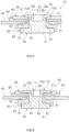
- FIG. 4 is a view that schematically shows a caulked part 53 of the terminal 50.
- FIG. 5 is a cross sectional view of the terminal 50 at a V-V cross section of FIG. 4 .
- FIG. 6 is a cross sectional view of the terminal 50 at a VI-VI cross section of FIG. 4 .
- the terminal 50 includes a head part 51, a cylinder part 52, and the caulked part 53.
- the head part 51 is a portion arranged at the outside of the sealing plate 40 (here, a side opposite to the case main body 30).
- the head part 51 is an approximately flat-plate shaped portion larger than the attachment hole 45, and is arranged along an outside surface of the sealing plate 40.
- the cylinder part 52 is a portion that is inserted into the attachment hole 45 via the outside insulating member 60.
- the cylinder part 52 protrudes downward from a central part of the head part 51.
- the cylinder part 52 is, for example, a cylindrical portion that extends in an up and down direction.
- the caulked part 53 is a portion caulked with respect to the conductive member 55 of the terminal 50. In other words, it can be said that the caulked part 53 is a portion caulked with respect to the sealing plate 40.
- the caulked part 53 is provided at a lower end of the cylinder part 52 and protrudes to an outward of the cylinder part 52.
- the cylinder part 52 and the caulked part 53 each is formed in a shape corresponding to the attachment hole 45, and is formed here in an oval like shape as shown in FIG. 3 and FIG. 4 .
- the traverse cross section shapes of the cylinder part 52 and the caulked part 53 are oval like shapes.
- an inner circumferential surface and an outer circumferential surface of the cylinder part 52 are formed in oval like shapes.
- the outside insulating member 60 is attached over an region from an inner circumferential surface of the attachment hole 45 of the sealing plate 40 to a surface at the outside of the sealing plate 40 (in other words, a head part 51 side of the terminal 50).
- the outside insulating member 60 includes a base part 61, an insulation cylinder part 62, and a side wall 63.
- the base part 61 is a plate-shaped member that is attached to a portion of a surface at the outside of the sealing plate 40 around the attachment hole 45.
- the head part 51 of the terminal 50 is arranged on the base part 61.
- the insulation cylinder part 62 is a cylindrical portion that protrudes from a bottom surface of the base part 61.
- the insulation cylinder part 62 is a portion that is inserted into the attachment hole 45. Into the insulation cylinder part 62, the cylinder part 52 of the terminal 50 is inserted. The side wall 63 is standing from a peripheral edge of the base part 61. The head part 51 of the terminal 50 is surrounded by the side wall 63 of the outside insulating member 60.
- the outside insulating member 60 is arranged between the sealing plate 40 and the terminal 50, and secures insulation of them. In addition, the outside insulating member 60 secures the airtightness of the attachment hole 45 of the sealing plate 40.
- the outside insulating member 60 consists of a material outstanding for a chemical resistant property or a weather resistant property.
- PFA is used for the outside insulating member 60.
- PFA is a copolymer with tetrafluoroethylene and perfluoroalkoxyethylene (Tetrafluoroethylene-Perfluoroalkylvinylether Copolymer).
- the material used for the outside insulating member 60 is not restricted to PFA.
- the conductive member 55 is connected to the terminal 50.
- the conductive member 55 connected to the positive electrode terminal 50a is referred to as a positive electrode conductive member 55a, too.
- the conductive member 55 connected to the negative electrode terminal 50b is referred to as a negative electrode conductive member 55b, too.
- the conductive member 55 is arranged inside the case main body 30.
- the conductive member 55 is arranged along a surface at an inner side of the sealing plate 40, and is provided at a periphery of the attachment hole 45.
- the conductive member 55 is a plate-shaped member.
- the conductive member 55 includes a penetration hole 56 and a groove 57. The penetration hole 56 penetrates the conductive member 55.
- the penetration hole 56 corresponds to a shape of the cylinder part 52, and is here formed in an oval like shape.
- the groove 57 is formed at a portion of the conductive member 55 around the penetration hole 56.
- the groove 57 is a groove dented upwardly from a bottom surface of the conductive member 55.
- the caulked part 53 of the terminal 50 is arranged on the groove 57.
- the connecting member 70 is connected to the conductive member 55.
- the connecting member 70 is arranged at the inside of the case main body 30, and is arranged along an inner side surface of the sealing plate 40.
- the connecting member 70 connected to the positive electrode conductive member 55a is referred to as a positive electrode connecting member 70a, too.
- the connecting member 70 connected to the negative electrode conductive member 55b is referred to as a negative electrode connecting member 70b, too.
- the positive electrode connecting member 70a is to connect the positive electrode terminal 50a and the positive electrode sheet 21, and is connected to the positive electrode conductive member 55a and the positive electrode collector tab 21a.
- the negative electrode connecting member 70b is to connect the negative electrode terminal 50b and the negative electrode sheet 22, and is connected to the negative electrode conductive member 55b and the negative electrode collector tab 22a.
- the connecting member 70 includes a first plate part 71, a second plate part 72, and a step part 73.
- the first plate part 71 is a portion arranged along a surface of the conductive member 55, and is connected to the conductive member 55.
- the first plate part 71 is a flat-plate shaped portion.
- the second plate part 72 is a portion arranged along a surface at an inner side of the sealing plate 40.
- the second plate part 72 is a flat-plate shaped portion.
- the second plate part 72 of the positive electrode connecting member 70a is joined to the positive electrode collector tab 21a.
- the second plate part 72 of the negative electrode connecting member 70b is joined to the negative electrode collector tab 22a.
- the step part 73 is a portion standing from one end part of the first plate part 71 to one end part of the second plate part 72 and coupling the first plate part 71 and the second plate part 72.
- the step part 73 is arranged along an end of the conductive member 55.
- inside insulating members 80 are provided between the conductive member 55 and the sealing plate 40, and between the connecting member 70 and the sealing plate 40.
- the conductive member 55 and the connecting member 70 are attached to the sealing plate 40 via the inside insulating member 80.
- the inside insulating member 80 includes a flat part 81, a hole 82, and a side wall 83.
- the flat part 81 is a portion arranged along a surface at an inner side of the sealing plate 40.
- the flat part 81 is a flat-plate shaped portion.
- the hole 82 is a hole provided correspondingly to the attachment hole 45 of the sealing plate 40, into which the cylinder part 52 of the terminal 50 is inserted.
- the hole 82 is formed on the flat part 81 and penetrates the flat part 81.
- the hole 82 is formed in a shape corresponding to the cylinder part 52, and the hole here is formed in an oval like shape.
- the side wall 83 is extending downward from a peripheral edge part of the flat part 81.
- the conductive member 55 and the connecting member 70 are surrounded by the side wall 83.
- the inside insulating member 80 is arranged inside the case main body 30, and thus it is preferable that the inside insulating member 80 has a necessary chemical resistant property.
- PPS is used for the inside insulating member 80.
- PPS is a polyphenylene sulfide resin.
- a material used for the inside insulating member 80 is not restricted to PPS.
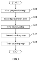
- the manufacturing method for the secondary battery 10 includes a first preparation step S11, a second preparation step S12, a first caulking step S13, a second caulking step S14, and a third caulking step S15.
- FIG. 8A is a cross sectional view that shows the terminal 50 before caulking.
- FIG. 8B , FIG. 8C, and FIG. 8D are cross sectional views respectively showing states of the terminal 50 during the first caulking step S13, the second caulking step S14, and the third caulking step S15.
- drawings of the sealing plate 40, the outside insulating member 60, and the inside insulating member 80 are omitted.
- the terminal 50 includes a shaft part 54.
- the shaft part 54 is a portion provided at the head part 51 (see FIG. 5 ).
- the shaft part 54 is a portion that can become the cylinder part 52 and the caulked part 53 after the terminal 50 is caulked, as shown in FIG. 8C .
- the shaft part 54 by caulking the shaft part 54, it is possible to fix the terminal 50 to the sealing plate 40.
- a portion being caulked becomes the caulked part 53 and a portion being not caulked becomes the cylinder part 52.
- the shaft part 54 is formed in a cylindrical shape.
- the shaft part 54 is formed in an oval like shape, and for more details, a shape of a traverse cross section of the shaft part 54 is the oval like shape.
- a shape of the inner circumferential surface of the shaft part 54 and a shape of the outer circumferential surface of the shaft part each is the oval like shape.
- the terminal 50 including the shaft part 54 is inserted into the attachment hole 45 formed on the sealing plate 40 to make the shaft part 54 protrude from the sealing plate 40.
- the outside insulating member 60 is inserted into the attachment hole 45 of the sealing plate 40.
- the insulation cylinder part 62 of the outside insulating member 60 is inserted into the attachment hole 45 to make the base part 61 of the outside insulating member 60 be attached to the outside surface of the sealing plate 40. Then, as shown in FIG.
- the shaft part 54 of the terminal 50 is inserted into the insulation cylinder part 62 that has been inserted into the attachment hole 45.
- the head part 51 of the terminal 50 is arranged on the base part 61 of the outside insulating member 60, to induce a state where a part (here, tip end part) of the shaft part 54 (see FIG. 8A ) protrudes to an inner side of the sealing plate 40, in other words, to a case main body 30 side.
- the conductive member 55 is arranged.
- the conductive member 55 is arranged on a surface at a side where the shaft part 54 of the sealing plate 40 protrude at the periphery of the attachment hole 45, in other words, on a surface at an inner side of the sealing plate 40.
- the inside insulating member 80 is arranged at first.
- the hole 82 is formed on the inside insulating member 80.
- the inside insulating member 80 is arranged on the surface at the inner side of the sealing plate 40.
- the conductive member 55 is arranged on the surface at the inner side of the sealing plate 40 via the inside insulating member 80.
- the conductive member 55 is arranged.
- the conductive member 55 is arranged on the flat part 81 of the inside insulating member 80.
- the second preparation step S12 is performed after the first preparation step S11, but the second preparation step S12 might be performed before the first preparation step S11.
- the first caulking step S13 to the third caulking step S15 are performed in an order after the first preparation step S11 and the second preparation step S12 are performed.
- the first caulking step S13 of FIG. 7 is performed.
- an inner diameter of the shaft part 54 of the terminal 50 is expanded.
- a first caulking tool 100 is used.
- FIG. 9 is a view showing the first caulking tool 100 and is a view in which the first caulking tool 100 is viewed from a tip end part 101 side.
- the first caulking tool 100 includes a tip end part 101 and a base end part 102.
- the tip end part 101 is a portion that is inserted into the cylindrical shaft part 54 of the terminal 50.
- the tip end part 101 has a shape corresponding to the inner circumferential surface of the shaft part 54, and the shape here is an oval like shape as shown in FIG. 9 .
- a shape of a traverse cross section of the tip end part 101 is the oval like shape.
- the base end part 102 is connected to the tip end part 101.
- the tip end part 101 protrudes from the base end part 102.
- the base end part 102 is formed in a complete round shape whose diameter is larger than the tip end part 101.
- a shape of a traverse cross section of the base end part 102 is the complete round shape.
- the phrase "whose diameter is larger than the tip end part 101" means that it is larger than a long diameter of the tip end part 101 formed in the oval like shape.
- the base end part 102 includes a reduced diameter portion 103.
- the reduced diameter portion 103 is a portion whose diameter is getting smaller toward the tip end part 101.
- An outer circumferential surface of the reduced diameter portion 103 is an inclined surface that is inclined to a central axis of the base end part 102 more toward the tip end part 101.
- the reduced diameter portion 103 continues to the tip end part 101.
- the wording "complete round” semantically contains a case of a strictly complete round and a case where a little error is caused on the diameters. For example, it is possible to determine whether it is a strictly complete round or not, by measuring a complete round degree of the base end part 102. In order to measure the complete round degree, for example, the base end part 102 is cut in a diameter direction into 4 equal sections or 8 equal sections. Then, regarding a distance between opposed two points of equally divided boundary points, for example, a micrometer is used to measure a plurality of such distances.
- the complete round degree is a numerical value obtained by dividing 2 into a difference between the maximum value and the minimum value among a plurality of distances regarding such two points.
- the complete round semantically contains a case where the complete round degree is 0 to 1 mm, preferably the complete round degree is 0 to 0.1 mm, or more preferably the complete round degree is 0 to 0.01 mm.
- the first caulking tool 100 is used to insert the tip end part 101 into the shaft part 54 of the terminal 50, so as to make the base end part 102 expand an inner diameter of a portion of the shaft part 54 protruding from the sealing plate 40.
- the reduced diameter portion 103 of the base end part 102 is used to expand the inner diameter of the portion of the shaft part 54 protruding from the sealing plate 40.
- the tip end part 101 of the first caulking tool 100 is formed in an oval like shape, and thus the inner circumferential surface of the shaft part 54 is uniformly widen when the tip end part 101 was inserted into the oval-like-shaped shaft part 54.
- the reduced diameter portion 103 of the base end part 102 formed in the complete round shape is expanded outwardly in a short diameter direction D12 (see FIG. 3 ) of the oval like shape from a portion of the shaft part 54 along a long diameter direction D11 (see FIG. 3 ) of the oval like shape, among the inner circumferential surface of the shaft part 54.
- the outer circumferential surface of the reduced diameter portion 103 is an inclined surface, and the inner diameter of the shaft part 54 is expanded along the outer circumferential surface of the reduced diameter portion 103.
- the second caulking tool 110 includes a flat surface 111.
- the flat surface 111 is a surface being flat, and has a shape larger than the caulked part 53 of the terminal 50, for example, has a shape which is one size larger than the attachment hole 45 (see FIG. 8A ) formed on the sealing plate 40.
- the flat surface 111 might be formed in a round shape, or might be formed in a rectangular shape.
- the second caulking tool 110 is used to make the flat surface 111 push the expanded portion of the shaft part 54. Then, the second caulking tool 110 is pushed toward the shaft part 54 side so as to make the flat surface 111 press the expanded portion of the shaft part 54.
- the number of pressing operations at the second caulking step S14 might be 1, or might be plural.
- the expanded portion of the shaft part 54 becomes to have a flat surface. This expanded portion will be the caulked part 53 of the terminal 50.
- the caulked part 53 is formed in an oval like shape.
- the expanded portion of the shaft part 54 pressed to be flat at the second caulking step S14 of FIG. 7 (hereinafter, referred to as caulked part 53) is pressed to form a step 53d.
- the step 53d is, as shown in FIG. 4 , formed at a peripheral edge part of the both sides in the long diameter direction D11 of the oval like shape of the caulked part 53.
- a third caulking tool 120 is used.
- the third caulking tool 120 includes a base end part 121, and a first press part 122 and a second press part 123 that protrude downward from a base end part 121.
- the first press part 122 and the second press part 123 are arranged in an opposed manner, correspondingly to the peripheral edge parts at the both sides in the long diameter direction D11 of the caulked part 53.
- a bottom surface of the first press part 122 and a bottom surface of the second press part 123 each is formed in an U shape.
- the first press part 122 and the second press part 123 are arranged.
- the third caulking tool 120 is used to make the first press part 122 and the second press part 123 press the peripheral edge parts at the both sides in the long diameter direction D11 of the caulked part 53.
- the steps 53d dented to the sealing plate 40 (see FIG. 8A ) side are formed.
- the shape of this step 53d becomes the same as the shape of the bottom surface of the first press part 122 and as the shape of the bottom surface of the second press part 123, and the shape here is an U shape as shown in FIG. 4 .
- the number of pressing operations performed at the third caulking step S15 might be 1, or might be plural.
- the terminal 50 includes the caulked part 53 being caulked with respect to the conductive member 55 and being formed in an oval like shape, as shown in FIG. 4 .
- the caulked part 53 includes a long diameter part 53a being along the long diameter direction D11 of the oval like shape, and a short diameter part 53b being along the short diameter direction D12 of the oval like shape.
- Two long diameter parts 53a configure the peripheral edge parts at both sides in the short diameter direction D12 of the caulked part 53.
- Two short diameter parts 53b configure the peripheral edge parts excluding the steps 53d of the peripheral edge parts at the both sides in the long diameter direction D11 of the caulked part 53.
- a length L1 in the short diameter direction D12 of the long diameter part 53a is longer than a length L2 in the long diameter direction D11 of the short diameter part 53b.
- the length L1 of the long diameter part 53a means a maximum length in the short diameter direction D12 of the long diameter part 53a.
- the length L2 of the short diameter part 53b means a maximum length in the long diameter direction D11 of the short diameter part 53b.
- a rate of a thickness T11 (see FIG. 6 ) of the long diameter part 53a with respect to a thickness T12 (see FIG. 5 ) of the short diameter part 53b is 0.9 to 1.1, or preferably 0.95 to 1.05.
- the thickness T11 of the long diameter part 53a means an average thickness of two long diameter parts 53a.
- the thickness T12 of the short diameter part 53b means an average thickness of two short diameter parts 53b.
- a rate of the thickness T12 of the short diameter part 53b with respect to the thickness T11 of the long diameter part 53a is also 0.9 to 1.1, or preferably 0.95 to 1.05.
- the thickness T11 of the long diameter part 53a might be the same as the thickness T12 of the short diameter part 53b, or might be thinner or thicker than the thickness T12 of the short diameter part 53b.
- the portion of the caulked part 53 on which the step 53d has been added at the third caulking step S15 is welded with the conductive member 55.
- the first caulking step S13 to the third caulking step S15 in a case where an oil is used when the terminal 50 is caulked, it is preferable to remove the oil with an air blow device or the like before the welding with the caulked part 53 and the conductive member 55.
- the manufacturing method for the secondary battery 10 includes the first preparation step S11, the second preparation step S12, the first caulking step S13, and the second caulking step S14.
- the terminal 50 including the shaft part 54 cylindrically formed in the oval like shape is inserted into the attachment hole 45 formed on the sealing plate 40 of the secondary battery 10, so as to make the shaft part 54 protrude from the sealing plate 40.
- the conductive member 55 is arranged on a surface at a side where the shaft part 54 of the sealing plate 40 protrudes at the periphery of the attachment hole 45.
- the first caulking step S13 as shown in FIG.
- the first caulking tool 100 including the tip end part 101 formed in the oval like shape as shown in FIG. 9 and including the base end part 102 formed in the complete round shape whose diameter is larger than the tip end part 101, is used to insert the tip end part 101 into the shaft part 54 of the terminal 50, so as to make the base end part 102 expand the inner diameter of the portion protruding from the sealing plate 40 among the shaft part 54.
- the second caulking step S14 as shown in FIG. 8C , the portion of the shaft part 54 expanded at the first caulking step S13 is pressed to be flat.
- the terminal 50 includes the caulked part 53 having been caulked in the oval like shape with respect to the conductive member 55.
- the caulked part 53 includes the long diameter part 53a along the long diameter direction D11 of the oval like shape, and the short diameter part 53b along the short diameter direction D12 of the oval like shape.
- the length L1 in the short diameter direction D12 of the long diameter part 53a is longer than the length L2 in the long diameter direction D11 of the short diameter part 53b.
- the shaft part 54 formed in the oval like shape of the terminal 50 is expanded.
- a portion to become the long diameter part 53a is outwardly widened at first, and then a portion to become the short diameter part 53b is outwardly widened.
- the length L1 of the long diameter part 53a becomes longer than the length L2 of the short diameter part 53b.
- the rate of the thickness T11 (see FIG. 6 ) of the long diameter part 53a with respect to the thickness T12 (see FIG. 5 ) of the short diameter part 53b is 0.9 to 1.1.
- the applicant of the present application performed tests in which, with below-described Example 1 and Example 2 of manufacturing methods for the secondary battery 10, the shaft part 54 of the terminal 50 was caulked and the rate (T11/T12) of the thickness T11 of the long diameter part 53a with respect to the thickness T12 of the short diameter part 53b was calculated.
- the first caulking tool 100 as shown in FIG. 8B and FIG. 9 in other words, the first caulking tool 100 whose tip end part 101 was formed in the oval like shape was used to caulk the terminal 50.
- the first caulking tool was used, in which the tip end part of the first caulking tool was formed in the complete round shape, to caulk the terminal 50.
- Example 1 the procedure of the first preparation step S11, the second preparation step S12, the second caulking step S14, and the third caulking step S15 is the same.
- the manufacturing method for Example 1 was performed on 10 terminals 50, total 10 times. Then, for each of the plurality of terminals 50, the rate of the thickness T11 of the long diameter part 53a with respect to the thickness T12 of the short diameter part 53b was calculated.
- the manufacturing method of Example 2 was performed on 10 terminals 50, total 10 times. Then, for each of the plurality of terminals 50, the rate of the thickness T11 of the long diameter part 53a with respect to the thickness T12 of the short diameter part 53b was calculated.
- the rate (T11/T12) was 0.9 to 1.1. An average of the rates (T11/T12) in Example 1 was 0.964.
- the rate (T11/T12) was 0.8 to 0.9. An average of the rates (T11/T12) in Example 2 was 0.864.
- the value of the rate (T11/T12) can be closer to 1.0 and the variation in the thicknesses of the caulked part 53 of the terminal 50 can be inhibited.
- the base end part 102 of the first caulking tool 100 includes the reduced diameter portion 103 whose diameter becomes smaller toward the tip end part 101.
- the reduced diameter portion 103 of the base end part 102 is used to expand the inner diameter of the portion of the shaft part 54 protruding from the sealing plate 40.
- the portion of the shaft part 54 protruding from the sealing plate 40 has the inner diameter being gradually expanded, depending on the diameter of the reduced diameter portion 103.
- the manufacturing method for the secondary battery 10 includes, as shown in FIG. 8D , the third caulking step S15 (see FIG. 7 ) for pressing the peripheral edge part in the long diameter direction D11 of the oval like shape, of the expanded portion of the shaft part 54 pressed to be flat at the second caulking step S14 of FIG. 7 , so as to form the step 53d.
- the portion provided with the step 53d becomes in a pressed state, and thus it is possible to hardly form a gap between the portion of the shaft part 54 provided with the step 53d and the conductive member 55. Therefore, it is possible to properly perform welding at the portion provided with the step 53d by welding with the conductive member 55.
- the electrode body 20 was a laminate type of the electrode body on which the positive electrode sheet 21, the negative electrode sheet 22, and the separator 23 are laminated.
- the electrode body 20 might be a wound type of the electrode body on which the positive electrode sheet 21, the negative electrode sheet 22, and the separator 23 are wound in a state of being superimposed.
Landscapes
- Chemical & Material Sciences (AREA)
- Chemical Kinetics & Catalysis (AREA)
- Electrochemistry (AREA)
- General Chemical & Material Sciences (AREA)
- Engineering & Computer Science (AREA)
- Manufacturing & Machinery (AREA)
- Connection Of Batteries Or Terminals (AREA)
Abstract
Description
- The present disclosure relates to a manufacturing method for a secondary battery, and to the secondary battery.
- For example,
Japanese Patent Application Publication No. 2008-270167 - For example,
Japanese Patent Application Patent No. 6577998 - Anyway, on the electrode outside terminal disclosed by
Japanese Patent Application Publication No. 2008-270167 Japanese Patent Application Patent No. 6577998 - A manufacturing method for a secondary battery proposed here includes a first preparation step, a second preparation step, a first caulking step, and a second caulking step. At the first preparation step, a terminal formed in an oval like shape and having a cylindrical shaft part is inserted into an attachment hole formed on a sealing plate of a secondary battery that includes a case main body whose part is opened and includes the sealing plate provided at the opening of the case main body, so as to make the shaft part protrude from the sealing plate. At the second preparation step, a conductive member is arranged at a periphery of the attachment hole and on a surface at a side where the shaft part of the sealing plate protrudes. At the first caulking step, a caulking tool having a tip end part formed in an oval like shape and having a base end part formed in a complete round shape whose diameter is larger than the tip end part is used to insert the tip end part into the shaft part of the terminal, so as to make the base end part expand an inner diameter of a portion of the shaft part protruding from the sealing plate. At the second caulking step, the portion of the shaft part expanded at the first caulking step is pressed to be flat.
- According to the manufacturing method for the secondary battery proposed here, it is possible by the tip end part formed in the oval like shape of the caulking tool to uniformly abut the inner circumferential surface of the shaft part formed in the oval like shape. Then, the base end part formed in the complete round shape of the caulking tool is abutted on the shaft part, to outwardly widen from a portion of the shaft part along the long diameter direction of the oval like shape, and thus it is possible to inhibit variation in the thicknesses of the caulked portion of the shaft part. Therefore, it is possible to secure the caulking strength for the terminal.
- According to the manufacturing method for the secondary battery proposed here, the base end part might include a reduced diameter portion whose diameter becomes smaller toward the tip end part. At the first caulking step, the reduced diameter portion of the base end part might be used to expand the inner diameter of the portion of the shaft part protruding from the sealing plate.
- The manufacturing method for the secondary battery proposed here might include a third caulking step for pressing to form a step on a peripheral edge part in a long diameter direction of the oval like shape of the expanded portion of the shaft part pressed to be flat at the second caulking step.
- The secondary battery proposed here includes a case main body whose part is opened, a sealing plate that is provided at the opening of the case main body, a terminal that is attached to the sealing plate, and a conductive member that is connected to the terminal. The terminal includes a caulked part that is caulked with respect to the conductive member and is formed in an oval like shape. The caulked part includes a long diameter part that is along a long diameter direction of the oval like shape, and a short diameter part that is along a short diameter direction of the oval like shape. A length of the long diameter part in the short diameter direction is longer than a length of the short diameter part in the long diameter direction.
- In the secondary battery proposed here, a rate of a thickness of the long diameter part with respect to a thickness of the short diameter part might be 0.9 to 1.1.
-
- [
FIG. 1] FIG. 1 is a perspective view that schematically shows a secondary battery in accordance with an embodiment. - [
FIG. 2] FIG. 2 is a cross sectional view of the secondary battery at a II-II cross section ofFIG. 1 , and a view that is schematically shown. - [
FIG. 3] FIG. 3 is a plane view that schematically shows an attachment hole of a sealing plate. - [
FIG. 4] FIG. 4 is a view that schematically shows a caulked part of a terminal. - [
FIG. 5] FIG. 5 is a cross sectional view of the terminal at a V-V cross section ofFIG. 4 , and a view that is schematically shown. - [
FIG. 6] FIG. 6 is a cross sectional view of the terminal at a VI-VI cross section ofFIG. 4 , and a view that is schematically shown. - [
FIG. 7] FIG. 7 is a flowchart that shows a method for caulking and fixing the terminal to a sealing plate. - [
FIG. 8A] FIG. 8A is a cross sectional view that schematically shows the terminal before caulking. - [
FIG. 8B] FIG. 8B is a cross sectional view that schematically shows a state of the terminal while a first caulking step is performed. - [
FIG. 8C] FIG. 8C is a cross sectional view that schematically shows a state of the terminal while a second caulking step is performed. - [
FIG. 8D] FIG. 8D is a cross sectional view that schematically shows a state of the terminal while a third caulking step is performed. - [
FIG. 9] FIG. 9 is a view that schematically shows a first caulking tool and a view that is viewed from a tip end part side. - [
FIG. 10] FIG. 10 is a graph that shows a result of a rate of a thickness of a long diameter part with respect to a thickness of a short diameter part of a caulked part. - Below, one embodiment of a herein disclosed secondary battery will be explained with drawings. The matters other than matters particularly mentioned in this specification, and required for practicing the present invention can be grasped as design matters of those skilled in the art based on the related art in the present field. The present disclosure can be implemented on the basis of contents disclosed in the present specification and a common general technical knowledge of this field. Incidentally, in the following accompanying drawings, the members/parts providing the same effect are given the same numerals and signs.
- In the present specification, the "battery" is a term denoting an electric storage device capable of extracting the electric energy in general, and is a concept including a primary battery and a secondary battery. The term "secondary battery" means an electric storage device in general that can be repeatedly charged and discharged, and semantically covers a so-called storage battery, such as a lithium secondary battery, a nickel hydrogen battery, and a nickel cadmium battery. Below, a lithium ion secondary battery, which is one kind of the secondary battery, is taken as an example, and then the herein disclosed secondary battery will be described in details. However, the herein disclosed secondary battery is not restricted to the lithium ion secondary battery in accordance with the embodiment explained here.
-
FIG. 1 is a perspective view of asecondary battery 10 in accordance with the present embodiment.FIG. 2 is a cross sectional view of thesecondary battery 10 at a II-II cross section ofFIG. 1 . As shown inFIG. 1 andFIG. 2 , thesecondary battery 10 includes anelectrode body 20, a casemain body 30, and a sealingplate 40. - As shown in
FIG. 2 , theelectrode body 20 is a power generating element of thesecondary battery 10. Theelectrode body 20 includes apositive electrode sheet 21 as a positive electrode element, anegative electrode sheet 22 as a negative electrode element, and a sheet-shapedseparator 23. Theseparator 23 is arranged between thepositive electrode sheet 21 and thenegative electrode sheet 22. In theelectrode body 20, thepositive electrode sheet 21, thenegative electrode sheet 22, and theseparator 23 are laminated. Theelectrode body 20 in accordance with the present embodiment has a laminate type structure in which thepositive electrode sheet 21 and thenegative electrode sheet 22, formed into predetermined shapes, are overlaid via theseparator 23. - The
positive electrode sheet 21 includes, for example, a positive electrode collector foil that is formed in a rectangular shape, a positive electrode active material layer that is formed on both surfaces of the positive electrode collector foil, and a positiveelectrode collector tab 21a that protrudes from the positive electrode active material layer. The positive electrode collector foil is, for example, an aluminum foil. The positive electrode active material layer contains a positive electrode active substance. The positive electrode active substance, for example, in a lithium ion secondary battery, is a material like a lithium transition metal composite material that can release lithium ions at an electrically charging time and can absorb lithium ions at an electrically discharging time. However, in general, various materials other than the lithium transition metal composite material are proposed as the positive electrode active substance, and thus the positive electrode active substance is not particularly restricted. The positiveelectrode collector tab 21a is a part of the positive electrode collector foil and protrudes from the positive electrode active material layer. Here, the positiveelectrode collector tab 21a protrudes upward from the positive electrode active material layer. On the positiveelectrode collector tab 21a, the positive electrode active material layer is not formed. - The
negative electrode sheet 22 includes, for example, a negative electrode collector foil that is formed in a rectangular shape, a negative electrode active material layer that is formed on both surfaces of the negative electrode collector foil, and a negativeelectrode collector tab 22a that protrudes from the negative electrode active material layer. The negative electrode collector foil is, for example, a copper foil. The negative electrode active material layer contains a negative electrode active substance. The negative electrode active substance, for example, in a lithium ion secondary battery, is a material like a natural graphite that can store lithium ions at an electrically charging time and can release lithium ions, stored at the electrically charging time, at an electrically discharging time. However, in general, various materials other than the natural graphite are proposed as the negative electrode active substance, and thus the negative electrode active substance is not particularly restricted. The negativeelectrode collector tab 22a is a part of the negative electrode collector foil and protrudes from the negative electrode active material layer. Here, the negativeelectrode collector tab 22a protrudes upward from the negative electrode active material layer. On the negativeelectrode collector tab 22a, the negative electrode active material layer is not formed. - The
separator 23 is, for example, formed with a porous sheet (e.g., a film, a non-woven fabric, or the like) consisted of a resin, such as polyethylene (PE), polypropylene (PP), polyester, cellulose, and polyamide. - In the present embodiment, the
electrode body 20 is manufactured, in a state where a plurality of positiveelectrode collector tabs 21a are overlaid and a plurality of negativeelectrode collector tabs 22a are overlaid, by laminating thepositive electrode sheet 21 and thenegative electrode sheet 22 via theseparator 23. - As shown in
FIG. 2 , the casemain body 30 is a case including a space at the inside and a part of the case is opened. Here, the casemain body 30 accommodates theelectrode body 20 and, on the casemain body 30, anopening 31 is formed to accommodate theelectrode body 20. As shown inFIG. 1 , the casemain body 30 is formed in a rectangular shape, but the shape of the casemain body 30 is not particularly restricted. The casemain body 30 is formed, for example, with aluminum or with aluminum alloy whose main component is aluminum, but even a material for forming the casemain body 30 is not particularly restricted. - In the present embodiment, the case
main body 30 might accommodate an electrolyte in addition to theelectrode body 20. As the electrolyte, it is possible to use a nonaqueous electrolyte in which a supporting salt is dissolved into a nonaqueous type solvent. As an example of the nonaqueous type solvent, it is possible to use carbonate type solvent, such as ethylene carbonate, dimethyl carbonate, and ethyl methyl carbonate. As an example of the supporting salt, it is possible to use a fluorine-containing lithium salt, such as LiPF6. - The sealing
plate 40 is a plate-shaped member provided on theopening 31 of the casemain body 30. The sealingplate 40 is formed in a rectangular shape (here, oblong rectangle shape) longer in a predetermined direction. Here, in a state where the sealingplate 40 is attached to theopening 31, a peripheral edge part of the sealingplate 40 is joined to a rim of theopening 31 of the casemain body 30. It is preferable that this join is implemented, for example, by welding continuously without gaps and, for example, it is implemented by laser welding. The sealingplate 40 is formed, for example, with aluminum or with aluminum alloy whose main component is aluminum, but even a material for forming the sealingplate 40 is not particularly restricted. - In the present embodiment, as shown in
FIG. 1 , aninjection hole 41 and agas exhaust valve 43 is provided on the sealingplate 40. Theinjection hole 41 is a hole for injecting the electrolyte into the casemain body 30 after the sealingplate 40 is attached to the casemain body 30. As shown inFIG. 2 , it is possible to fit aplug 42 into theinjection hole 41. By fitting theplug 42 into theinjection hole 41, theinjection hole 41 is closed. Thegas exhaust valve 43 is a thin-walled part that is configured to be broken so as to exhaust gas inside the casemain body 30 to the outside of the casemain body 30 when an internal pressure of thesecondary battery 10 becomes equal to or more than a predetermined value. - The
secondary battery 10 in accordance with the present embodiment includes a terminal 50, aconductive member 55, and a connecting member 70. The terminal 50 is attached to the sealingplate 40. Here, the terminal 50 includes a positive electrode terminal 50a that is connected to thepositive electrode sheet 21 of theelectrode body 20, and includes a negative electrode terminal 50b that is connected to thenegative electrode sheet 22 of theelectrode body 20. Here, the positive electrode terminal 50a and the negative electrode terminal 50b have the same shape and the same configuration. Below, in explanations common for the positive electrode terminal 50a and the negative electrode terminal 50b, a wording ofterminal 50 would be used. -
FIG. 3 is a plane view in which anattachment hole 45 of the sealingplate 40 is schematically shown.FIG. 3 shows a state in which the terminal 50 cut by a traverse cross section is inserted into theattachment hole 45. In the present specification, the traverse cross section means a cross section cut in a horizontal direction. In the present embodiment, as shown inFIG. 3 , theattachment hole 45 is formed on the sealingplate 40. Theattachment hole 45 is formed in an oval like shape. Here, the oval means a curve geometrically similar to an egg shape, an ellipse shape, an oval shape. The oval like shape semantically contains an oval shape, a truck shape, an ellipse shape, an egg shape, and the like. In the present embodiment, a long diameter direction D11 of the oval like shape is the same as a longitudinal direction of the sealingplate 40. A short diameter direction D12 of the oval like shape is the same as a shorter direction of the sealingplate 40. - In the present embodiment, as shown in
FIG. 2 , the terminal 50 is attached to the sealingplate 40 in a state of being inserted into theattachment hole 45. Here, as shown inFIG. 3 , an outside insulatingmember 60 exists between a rim of theattachment hole 45 and the terminal 50. -
FIG. 4 is a view that schematically shows a caulkedpart 53 of the terminal 50.FIG. 5 is a cross sectional view of the terminal 50 at a V-V cross section ofFIG. 4 .FIG. 6 is a cross sectional view of the terminal 50 at a VI-VI cross section ofFIG. 4 . InFIG. 5 and FIG. 6 , the upper and lower positions ofFIG. 2 are reversed. In the present embodiment, as shown inFIG. 5 , the terminal 50 includes ahead part 51, acylinder part 52, and the caulkedpart 53. Thehead part 51 is a portion arranged at the outside of the sealing plate 40 (here, a side opposite to the case main body 30). Thehead part 51 is an approximately flat-plate shaped portion larger than theattachment hole 45, and is arranged along an outside surface of the sealingplate 40. - The
cylinder part 52 is a portion that is inserted into theattachment hole 45 via the outside insulatingmember 60. Thecylinder part 52 protrudes downward from a central part of thehead part 51. Thecylinder part 52 is, for example, a cylindrical portion that extends in an up and down direction. The caulkedpart 53 is a portion caulked with respect to theconductive member 55 of the terminal 50. In other words, it can be said that the caulkedpart 53 is a portion caulked with respect to the sealingplate 40. The caulkedpart 53 is provided at a lower end of thecylinder part 52 and protrudes to an outward of thecylinder part 52. In the present embodiment, thecylinder part 52 and the caulkedpart 53 each is formed in a shape corresponding to theattachment hole 45, and is formed here in an oval like shape as shown inFIG. 3 and FIG. 4 . In other words, the traverse cross section shapes of thecylinder part 52 and the caulkedpart 53 are oval like shapes. Here, an inner circumferential surface and an outer circumferential surface of thecylinder part 52 are formed in oval like shapes. - As shown in
FIG. 5 and FIG. 6 , the outside insulatingmember 60 is attached over an region from an inner circumferential surface of theattachment hole 45 of the sealingplate 40 to a surface at the outside of the sealing plate 40 (in other words, ahead part 51 side of the terminal 50). In the present embodiment, the outside insulatingmember 60 includes abase part 61, aninsulation cylinder part 62, and aside wall 63. Thebase part 61 is a plate-shaped member that is attached to a portion of a surface at the outside of the sealingplate 40 around theattachment hole 45. On thebase part 61, thehead part 51 of the terminal 50 is arranged. Theinsulation cylinder part 62 is a cylindrical portion that protrudes from a bottom surface of thebase part 61. Theinsulation cylinder part 62 is a portion that is inserted into theattachment hole 45. Into theinsulation cylinder part 62, thecylinder part 52 of the terminal 50 is inserted. Theside wall 63 is standing from a peripheral edge of thebase part 61. Thehead part 51 of the terminal 50 is surrounded by theside wall 63 of the outside insulatingmember 60. - The outside insulating
member 60 is arranged between the sealingplate 40 and the terminal 50, and secures insulation of them. In addition, the outside insulatingmember 60 secures the airtightness of theattachment hole 45 of the sealingplate 40. In consideration of the perspective described above, it is preferable that the outside insulatingmember 60 consists of a material outstanding for a chemical resistant property or a weather resistant property. In this embodiment, PFA is used for the outside insulatingmember 60. PFA is a copolymer with tetrafluoroethylene and perfluoroalkoxyethylene (Tetrafluoroethylene-Perfluoroalkylvinylether Copolymer). However, the material used for the outside insulatingmember 60 is not restricted to PFA. - As shown in
FIG. 2 , theconductive member 55 is connected to the terminal 50. Here, theconductive member 55 connected to the positive electrode terminal 50a is referred to as a positive electrode conductive member 55a, too. Theconductive member 55 connected to the negative electrode terminal 50b is referred to as a negative electrode conductive member 55b, too. Theconductive member 55 is arranged inside the casemain body 30. Theconductive member 55 is arranged along a surface at an inner side of the sealingplate 40, and is provided at a periphery of theattachment hole 45. Theconductive member 55 is a plate-shaped member. As shown inFIG. 5 , theconductive member 55 includes apenetration hole 56 and agroove 57. Thepenetration hole 56 penetrates theconductive member 55. Into thepenetration hole 56, thecylinder part 52 of the terminal 50 is inserted. Thepenetration hole 56 corresponds to a shape of thecylinder part 52, and is here formed in an oval like shape. Thegroove 57 is formed at a portion of theconductive member 55 around thepenetration hole 56. Thegroove 57 is a groove dented upwardly from a bottom surface of theconductive member 55. On thegroove 57, the caulkedpart 53 of the terminal 50 is arranged. - As shown in
FIG. 2 , the connecting member 70 is connected to theconductive member 55. The connecting member 70 is arranged at the inside of the casemain body 30, and is arranged along an inner side surface of the sealingplate 40. Here, the connecting member 70 connected to the positive electrode conductive member 55a is referred to as a positive electrode connecting member 70a, too. The connecting member 70 connected to the negative electrode conductive member 55b is referred to as a negative electrode connecting member 70b, too. The positive electrode connecting member 70a is to connect the positive electrode terminal 50a and thepositive electrode sheet 21, and is connected to the positive electrode conductive member 55a and the positiveelectrode collector tab 21a. The negative electrode connecting member 70b is to connect the negative electrode terminal 50b and thenegative electrode sheet 22, and is connected to the negative electrode conductive member 55b and the negativeelectrode collector tab 22a. - In the present embodiment, the connecting member 70 includes a first plate part 71, a
second plate part 72, and astep part 73. The first plate part 71 is a portion arranged along a surface of theconductive member 55, and is connected to theconductive member 55. The first plate part 71 is a flat-plate shaped portion. Thesecond plate part 72 is a portion arranged along a surface at an inner side of the sealingplate 40. Thesecond plate part 72 is a flat-plate shaped portion. Thesecond plate part 72 of the positive electrode connecting member 70a is joined to the positiveelectrode collector tab 21a. Thesecond plate part 72 of the negative electrode connecting member 70b is joined to the negativeelectrode collector tab 22a. Thestep part 73 is a portion standing from one end part of the first plate part 71 to one end part of thesecond plate part 72 and coupling the first plate part 71 and thesecond plate part 72. In the present embodiment, thestep part 73 is arranged along an end of theconductive member 55. - In the present embodiment, inside insulating
members 80 are provided between theconductive member 55 and the sealingplate 40, and between the connecting member 70 and the sealingplate 40. Theconductive member 55 and the connecting member 70 are attached to the sealingplate 40 via the inside insulatingmember 80. - The inside insulating
member 80 includes aflat part 81, ahole 82, and aside wall 83. Theflat part 81 is a portion arranged along a surface at an inner side of the sealingplate 40. Theflat part 81 is a flat-plate shaped portion. Thehole 82 is a hole provided correspondingly to theattachment hole 45 of the sealingplate 40, into which thecylinder part 52 of the terminal 50 is inserted. In the present embodiment, thehole 82 is formed on theflat part 81 and penetrates theflat part 81. Thehole 82 is formed in a shape corresponding to thecylinder part 52, and the hole here is formed in an oval like shape. Theside wall 83 is extending downward from a peripheral edge part of theflat part 81. Theconductive member 55 and the connecting member 70 are surrounded by theside wall 83. - The inside insulating
member 80 is arranged inside the casemain body 30, and thus it is preferable that the inside insulatingmember 80 has a necessary chemical resistant property. In the present embodiment, PPS is used for the inside insulatingmember 80. PPS is a polyphenylene sulfide resin. Incidentally, a material used for the inside insulatingmember 80 is not restricted to PPS. - Above, the
secondary battery 10 in accordance with the present embodiment has been explained. Next, a manufacturing method for thesecondary battery 10 will be described. Here, a method for caulking the terminal 50 and fixing to the sealingplate 40 will be explained according to a flowchart ofFIG. 7 . In the present embodiment, as shown inFIG. 7 , the manufacturing method for thesecondary battery 10 includes a first preparation step S11, a second preparation step S12, a first caulking step S13, a second caulking step S14, and a third caulking step S15. -
FIG. 8A is a cross sectional view that shows the terminal 50 before caulking.FIG. 8B ,FIG. 8C, and FIG. 8D are cross sectional views respectively showing states of the terminal 50 during the first caulking step S13, the second caulking step S14, and the third caulking step S15. Incidentally, inFIG. 8B to FIG. 8D , drawings of the sealingplate 40, the outside insulatingmember 60, and the inside insulatingmember 80 are omitted. In the present embodiment, as shown inFIG. 8A , the terminal 50 includes ashaft part 54. Theshaft part 54 is a portion provided at the head part 51 (seeFIG. 5 ). - The
shaft part 54 is a portion that can become thecylinder part 52 and the caulkedpart 53 after the terminal 50 is caulked, as shown inFIG. 8C . Here, by caulking theshaft part 54, it is possible to fix the terminal 50 to the sealingplate 40. In theshaft part 54, a portion being caulked becomes the caulkedpart 53 and a portion being not caulked becomes thecylinder part 52. In the present embodiment, theshaft part 54 is formed in a cylindrical shape. Theshaft part 54 is formed in an oval like shape, and for more details, a shape of a traverse cross section of theshaft part 54 is the oval like shape. A shape of the inner circumferential surface of theshaft part 54 and a shape of the outer circumferential surface of the shaft part each is the oval like shape. - In the present embodiment, at the first preparation step S11 of
FIG. 7 , as shown inFIG. 8A , the terminal 50 including theshaft part 54 is inserted into theattachment hole 45 formed on the sealingplate 40 to make theshaft part 54 protrude from the sealingplate 40. In the present embodiment, at first, the outside insulatingmember 60 is inserted into theattachment hole 45 of the sealingplate 40. Here, as shown inFIG. 5 , theinsulation cylinder part 62 of the outside insulatingmember 60 is inserted into theattachment hole 45 to make thebase part 61 of the outside insulatingmember 60 be attached to the outside surface of the sealingplate 40. Then, as shown inFIG. 8A , theshaft part 54 of the terminal 50 is inserted into theinsulation cylinder part 62 that has been inserted into theattachment hole 45. At that time, as shown inFIG. 5 , thehead part 51 of the terminal 50 is arranged on thebase part 61 of the outside insulatingmember 60, to induce a state where a part (here, tip end part) of the shaft part 54 (seeFIG. 8A ) protrudes to an inner side of the sealingplate 40, in other words, to a casemain body 30 side. - Next, at the second preparation step S12 of
FIG. 7 , as shown inFIG. 8A , theconductive member 55 is arranged. Here, theconductive member 55 is arranged on a surface at a side where theshaft part 54 of the sealingplate 40 protrude at the periphery of theattachment hole 45, in other words, on a surface at an inner side of the sealingplate 40. In the present embodiment, at first, the inside insulatingmember 80 is arranged. Here, thehole 82 is formed on the inside insulatingmember 80. To overlap thishole 82 with theattachment hole 45 of the sealingplate 40, the inside insulatingmember 80 is arranged on the surface at the inner side of the sealingplate 40. Then, theconductive member 55 is arranged on the surface at the inner side of the sealingplate 40 via the inside insulatingmember 80. Here, to make thepenetration hole 56 formed on theconductive member 55 be overlapped with theattachment hole 45 of the sealingplate 40 and thehole 82 of the inside insulatingmember 80, theconductive member 55 is arranged. At that time, theconductive member 55 is arranged on theflat part 81 of the inside insulatingmember 80. - Incidentally, in the present embodiment, the second preparation step S12 is performed after the first preparation step S11, but the second preparation step S12 might be performed before the first preparation step S11.
- Although described above, as shown in
FIG. 7 , the first caulking step S13 to the third caulking step S15 are performed in an order after the first preparation step S11 and the second preparation step S12 are performed. Here, at first, the first caulking step S13 ofFIG. 7 is performed. At the first caulking step S13, as shown inFIG. 8B , an inner diameter of theshaft part 54 of the terminal 50 is expanded. At the first caulking step S13, afirst caulking tool 100 is used. -
FIG. 9 is a view showing thefirst caulking tool 100 and is a view in which thefirst caulking tool 100 is viewed from atip end part 101 side. As shown inFIG. 8B andFIG. 9 , thefirst caulking tool 100 includes atip end part 101 and abase end part 102. As shown inFIG. 8B , thetip end part 101 is a portion that is inserted into thecylindrical shaft part 54 of the terminal 50. Thetip end part 101 has a shape corresponding to the inner circumferential surface of theshaft part 54, and the shape here is an oval like shape as shown inFIG. 9 . A shape of a traverse cross section of thetip end part 101 is the oval like shape. - As shown in
FIG. 8B , thebase end part 102 is connected to thetip end part 101. In other words, thetip end part 101 protrudes from thebase end part 102. As shown inFIG. 9 , thebase end part 102 is formed in a complete round shape whose diameter is larger than thetip end part 101. A shape of a traverse cross section of thebase end part 102 is the complete round shape. Here, the phrase "whose diameter is larger than thetip end part 101" means that it is larger than a long diameter of thetip end part 101 formed in the oval like shape. In the present embodiment, as shown inFIG. 8B , thebase end part 102 includes a reduceddiameter portion 103. The reduceddiameter portion 103 is a portion whose diameter is getting smaller toward thetip end part 101. An outer circumferential surface of the reduceddiameter portion 103 is an inclined surface that is inclined to a central axis of thebase end part 102 more toward thetip end part 101. Here, the reduceddiameter portion 103 continues to thetip end part 101. - In the present embodiment, the wording "complete round" semantically contains a case of a strictly complete round and a case where a little error is caused on the diameters. For example, it is possible to determine whether it is a strictly complete round or not, by measuring a complete round degree of the
base end part 102. In order to measure the complete round degree, for example, thebase end part 102 is cut in a diameter direction into 4 equal sections or 8 equal sections. Then, regarding a distance between opposed two points of equally divided boundary points, for example, a micrometer is used to measure a plurality of such distances. The complete round degree is a numerical value obtained by dividing 2 into a difference between the maximum value and the minimum value among a plurality of distances regarding such two points. In the present embodiment, the complete round semantically contains a case where the complete round degree is 0 to 1 mm, preferably the complete round degree is 0 to 0.1 mm, or more preferably the complete round degree is 0 to 0.01 mm. - At the first caulking step S13 of
FIG. 7 , as shown inFIG. 8B , thefirst caulking tool 100 is used to insert thetip end part 101 into theshaft part 54 of the terminal 50, so as to make thebase end part 102 expand an inner diameter of a portion of theshaft part 54 protruding from the sealingplate 40. Here, the reduceddiameter portion 103 of thebase end part 102 is used to expand the inner diameter of the portion of theshaft part 54 protruding from the sealingplate 40. Here, thetip end part 101 of thefirst caulking tool 100 is formed in an oval like shape, and thus the inner circumferential surface of theshaft part 54 is uniformly widen when thetip end part 101 was inserted into the oval-like-shapedshaft part 54. Then, by the reduceddiameter portion 103 of thebase end part 102 formed in the complete round shape, it is expanded outwardly in a short diameter direction D12 (seeFIG. 3 ) of the oval like shape from a portion of theshaft part 54 along a long diameter direction D11 (seeFIG. 3 ) of the oval like shape, among the inner circumferential surface of theshaft part 54. In the present embodiment, the outer circumferential surface of the reduceddiameter portion 103 is an inclined surface, and the inner diameter of theshaft part 54 is expanded along the outer circumferential surface of the reduceddiameter portion 103. - Next, at the second caulking step S14 of
FIG. 7 , as shown inFIG. 8C , the portion of theshaft part 54 expanded at the first caulking step S13 ofFIG. 7 is pressed to be flat. At the second caulking step S14, asecond caulking tool 110 different from thefirst caulking tool 100 is used. Thesecond caulking tool 110 includes aflat surface 111. Theflat surface 111 is a surface being flat, and has a shape larger than the caulkedpart 53 of the terminal 50, for example, has a shape which is one size larger than the attachment hole 45 (seeFIG. 8A ) formed on the sealingplate 40. Theflat surface 111 might be formed in a round shape, or might be formed in a rectangular shape. - At the second caulking step S14, the
second caulking tool 110 is used to make theflat surface 111 push the expanded portion of theshaft part 54. Then, thesecond caulking tool 110 is pushed toward theshaft part 54 side so as to make theflat surface 111 press the expanded portion of theshaft part 54. Incidentally, the number of pressing operations at the second caulking step S14 might be 1, or might be plural. By pressing with thesecond caulking tool 110, the expanded portion of theshaft part 54 becomes to have a flat surface. This expanded portion will be the caulkedpart 53 of the terminal 50. The caulkedpart 53 is formed in an oval like shape. - Next, at the third caulking step S15 of
FIG. 7 , as shown inFIG. 8D , the expanded portion of theshaft part 54 pressed to be flat at the second caulking step S14 ofFIG. 7 (hereinafter, referred to as caulked part 53) is pressed to form astep 53d. Thestep 53d is, as shown inFIG. 4 , formed at a peripheral edge part of the both sides in the long diameter direction D11 of the oval like shape of the caulkedpart 53. At the third caulking step S15 in accordance with the present embodiment, as shown inFIG. 8D , athird caulking tool 120 is used. Thethird caulking tool 120 includes abase end part 121, and afirst press part 122 and asecond press part 123 that protrude downward from abase end part 121. Thefirst press part 122 and thesecond press part 123 are arranged in an opposed manner, correspondingly to the peripheral edge parts at the both sides in the long diameter direction D11 of the caulkedpart 53. Although the illustrations are omitted, a bottom surface of thefirst press part 122 and a bottom surface of thesecond press part 123 each is formed in an U shape. Here, to make the U-shaped dented portions be opposed, thefirst press part 122 and thesecond press part 123 are arranged. - At the third caulking step S15, the
third caulking tool 120 is used to make thefirst press part 122 and thesecond press part 123 press the peripheral edge parts at the both sides in the long diameter direction D11 of the caulkedpart 53. At the peripheral edge parts in the long diameter direction D11 of the caulkedpart 53, which are pressed by thefirst press part 122 and thesecond press part 123, thesteps 53d dented to the sealing plate 40 (seeFIG. 8A ) side are formed. The shape of thisstep 53d becomes the same as the shape of the bottom surface of thefirst press part 122 and as the shape of the bottom surface of thesecond press part 123, and the shape here is an U shape as shown inFIG. 4 . Incidentally, the number of pressing operations performed at the third caulking step S15 might be 1, or might be plural. - As described above, regarding the terminal 50 caulked through the first caulking step S13 to the third caulking step S15, the terminal 50 includes the caulked
part 53 being caulked with respect to theconductive member 55 and being formed in an oval like shape, as shown inFIG. 4 . The caulkedpart 53 includes along diameter part 53a being along the long diameter direction D11 of the oval like shape, and ashort diameter part 53b being along the short diameter direction D12 of the oval like shape. In the present embodiment, there are twolong diameter parts 53a. Twolong diameter parts 53a configure the peripheral edge parts at both sides in the short diameter direction D12 of the caulkedpart 53. There are twoshort diameter parts 53b, too. Twoshort diameter parts 53b configure the peripheral edge parts excluding thesteps 53d of the peripheral edge parts at the both sides in the long diameter direction D11 of the caulkedpart 53. - In the present embodiment, a length L1 in the short diameter direction D12 of the
long diameter part 53a is longer than a length L2 in the long diameter direction D11 of theshort diameter part 53b. Here, the length L1 of thelong diameter part 53a means a maximum length in the short diameter direction D12 of thelong diameter part 53a. In addition, the length L2 of theshort diameter part 53b means a maximum length in the long diameter direction D11 of theshort diameter part 53b. - In the present embodiment, a rate of a thickness T11 (see
FIG. 6 ) of thelong diameter part 53a with respect to a thickness T12 (seeFIG. 5 ) of theshort diameter part 53b is 0.9 to 1.1, or preferably 0.95 to 1.05. Here, the thickness T11 of thelong diameter part 53a means an average thickness of twolong diameter parts 53a. The thickness T12 of theshort diameter part 53b means an average thickness of twoshort diameter parts 53b. In the present embodiment, a rate of the thickness T12 of theshort diameter part 53b with respect to the thickness T11 of thelong diameter part 53a is also 0.9 to 1.1, or preferably 0.95 to 1.05. Incidentally, when the rate of the thickness T11 of thelong diameter part 53a with respect to the thickness T12 of theshort diameter part 53b is within a range of 0.9 to 1.1, the thickness T11 of thelong diameter part 53a might be the same as the thickness T12 of theshort diameter part 53b, or might be thinner or thicker than the thickness T12 of theshort diameter part 53b. - Incidentally, in the present embodiment, after the first caulking step S13 to the third caulking step S15 of
FIG. 7 are performed, the portion of the caulkedpart 53 on which thestep 53d has been added at the third caulking step S15 is welded with theconductive member 55. Here, at the first caulking step S13 to the third caulking step S15, in a case where an oil is used when the terminal 50 is caulked, it is preferable to remove the oil with an air blow device or the like before the welding with the caulkedpart 53 and theconductive member 55. - From the above, in the present embodiment, as shown in
FIG. 7 , the manufacturing method for thesecondary battery 10 includes the first preparation step S11, the second preparation step S12, the first caulking step S13, and the second caulking step S14. At the first preparation step S11, as shown inFIG. 8A , the terminal 50 including theshaft part 54 cylindrically formed in the oval like shape is inserted into theattachment hole 45 formed on the sealingplate 40 of thesecondary battery 10, so as to make theshaft part 54 protrude from the sealingplate 40. At the second preparation step S12, theconductive member 55 is arranged on a surface at a side where theshaft part 54 of the sealingplate 40 protrudes at the periphery of theattachment hole 45. At the first caulking step S13, as shown inFIG. 8B , thefirst caulking tool 100, including thetip end part 101 formed in the oval like shape as shown inFIG. 9 and including thebase end part 102 formed in the complete round shape whose diameter is larger than thetip end part 101, is used to insert thetip end part 101 into theshaft part 54 of the terminal 50, so as to make thebase end part 102 expand the inner diameter of the portion protruding from the sealingplate 40 among theshaft part 54. At the second caulking step S14, as shown inFIG. 8C , the portion of theshaft part 54 expanded at the first caulking step S13 is pressed to be flat. - By doing this, as shown in
FIG. 8B , it is possible with thetip end part 101 formed in the oval like shape of thefirst caulking tool 100 to uniformly abut the inner circumferential surface of theshaft part 54 formed in the oval like shape. Then, by making thebase end part 102 formed in the complete round shape of thefirst caulking tool 100 abut theshaft part 54, it is possible to outwardly widen from a portion of theshaft part 54 along the long diameter direction D11 of the oval like shape, and thus it is possible to inhibit variation in the thicknesses of the caulked portion of theshaft part 54. Therefore, it is possible to secure the caulking strength of the terminal 50. - In the present embodiment, as shown in
FIG. 4 , the terminal 50 includes the caulkedpart 53 having been caulked in the oval like shape with respect to theconductive member 55. The caulkedpart 53 includes thelong diameter part 53a along the long diameter direction D11 of the oval like shape, and theshort diameter part 53b along the short diameter direction D12 of the oval like shape. The length L1 in the short diameter direction D12 of thelong diameter part 53a is longer than the length L2 in the long diameter direction D11 of theshort diameter part 53b. Here, at the first caulking step S13 ofFIG. 7 , as shown inFIG. 8B , by using thebase end part 102 formed in the complete round shape of thefirst caulking tool 100, theshaft part 54 formed in the oval like shape of the terminal 50 is expanded. At that time, a portion to become thelong diameter part 53a is outwardly widened at first, and then a portion to become theshort diameter part 53b is outwardly widened. As the result, the length L1 of thelong diameter part 53a becomes longer than the length L2 of theshort diameter part 53b. Thus, by using thebase end part 102 formed in the complete round shape to expand theshaft part 54 formed in the oval like shape, it is possible to make the length L1 of thelong diameter part 53a be longer than the length L2 of theshort diameter part 53b. - In the present embodiment, the rate of the thickness T11 (see
FIG. 6 ) of thelong diameter part 53a with respect to the thickness T12 (seeFIG. 5 ) of theshort diameter part 53b is 0.9 to 1.1. By doing this, it is possible to inhibit variation in the thicknesses of the caulkedpart 53, and thus it is possible to secure the caulking strength. - Anyway, the applicant of the present application performed tests in which, with below-described Example 1 and Example 2 of manufacturing methods for the
secondary battery 10, theshaft part 54 of the terminal 50 was caulked and the rate (T11/T12) of the thickness T11 of thelong diameter part 53a with respect to the thickness T12 of theshort diameter part 53b was calculated. - The
first caulking tool 100 as shown inFIG. 8B andFIG. 9 , in other words, thefirst caulking tool 100 whosetip end part 101 was formed in the oval like shape was used to caulk the terminal 50. - The first caulking tool was used, in which the tip end part of the first caulking tool was formed in the complete round shape, to caulk the terminal 50.
- Incidentally, not only in Example 1 but also in Example 2, the procedure of the first preparation step S11, the second preparation step S12, the second caulking step S14, and the third caulking step S15 is the same. Here, the manufacturing method for Example 1 was performed on 10
terminals 50, total 10 times. Then, for each of the plurality ofterminals 50, the rate of the thickness T11 of thelong diameter part 53a with respect to the thickness T12 of theshort diameter part 53b was calculated. Similarly, the manufacturing method of Example 2 was performed on 10terminals 50, total 10 times. Then, for each of the plurality ofterminals 50, the rate of the thickness T11 of thelong diameter part 53a with respect to the thickness T12 of theshort diameter part 53b was calculated. These results are shown inFIG. 10 . - While shown in
FIG. 10 , in a case where thefirst caulking tool 100 including the oval-like-shapedtip end part 101 was used like as Example 1 to caulk the terminal 50, the rate (T11/T12) was 0.9 to 1.1. An average of the rates (T11/T12) in Example 1 was 0.964. On the other hand, in the case where the first caulking tool including the complete-round-shaped tip end part was used like as Example 2 to caulk the terminal 50, the rate (T11/T12) was 0.8 to 0.9. An average of the rates (T11/T12) in Example 2 was 0.864. From these things, it can be understood that, by using thefirst caulking tool 100 including the oval-like-shapedtip end part 101, the value of the rate (T11/T12) can be closer to 1.0 and the variation in the thicknesses of the caulkedpart 53 of the terminal 50 can be inhibited. - In the present embodiment, as shown in
FIG. 8B , thebase end part 102 of thefirst caulking tool 100 includes the reduceddiameter portion 103 whose diameter becomes smaller toward thetip end part 101. At the first caulking step S13 ofFIG. 7 , the reduceddiameter portion 103 of thebase end part 102 is used to expand the inner diameter of the portion of theshaft part 54 protruding from the sealingplate 40. By doing this, the portion of theshaft part 54 protruding from the sealingplate 40 has the inner diameter being gradually expanded, depending on the diameter of the reduceddiameter portion 103. Thus, it is easy to expand the portion of theshaft part 54 protruding from the sealingplate 40. - In the present embodiment, the manufacturing method for the
secondary battery 10 includes, as shown inFIG. 8D , the third caulking step S15 (seeFIG. 7 ) for pressing the peripheral edge part in the long diameter direction D11 of the oval like shape, of the expanded portion of theshaft part 54 pressed to be flat at the second caulking step S14 ofFIG. 7 , so as to form thestep 53d. By doing this, the portion provided with thestep 53d becomes in a pressed state, and thus it is possible to hardly form a gap between the portion of theshaft part 54 provided with thestep 53d and theconductive member 55. Therefore, it is possible to properly perform welding at the portion provided with thestep 53d by welding with theconductive member 55. - In the present embodiment, the
electrode body 20 was a laminate type of the electrode body on which thepositive electrode sheet 21, thenegative electrode sheet 22, and theseparator 23 are laminated. However, theelectrode body 20 might be a wound type of the electrode body on which thepositive electrode sheet 21, thenegative electrode sheet 22, and theseparator 23 are wound in a state of being superimposed.
Claims (5)
- A manufacturing method for a secondary battery (10), comprising:a first preparation step (S11) for inserting a terminal (50) formed in an oval like shape and having a cylindrical shaft part (54) into an attachment hole (45) formed on a sealing plate (40) of a secondary battery (10) that comprises a case main body (30) whose part is opened and comprises the sealing plate (40) provided at the opening of the case main body (30), so as to make the shaft part (54) protrude from the sealing plate (40);a second preparation step (S12) for arranging a conductive member (55) at a periphery of the attachment hole (45) and on a surface at a side where the shaft part (54) of the sealing plate (40) protrudes;a first caulking step (S13) for using a caulking tool (100) having a tip end part (101) formed in an oval like shape and having a base end part (102) formed in a complete round shape whose diameter is larger than the tip end part (101), to insert the tip end part (101) into the shaft part (54) of the terminal (50), so as to make the base end part (102) expand an inner diameter of a portion of the shaft part (54) protruding from the sealing plate (40); anda second caulking step (S14) for pressing the portion of the shaft part (54) expanded at the first caulking step (S13) to be flat.
- The manufacturing method for the secondary battery (10) according to claim 1,wherein the base end part (102) comprises a reduced diameter portion (103) whose diameter becomes smaller toward the tip end part (101), andat the first caulking step (S13), the reduced diameter portion (103) of the base end part (102) is used to expand the inner diameter of the portion of the shaft part (54) protruding from the sealing plate (40).
- The manufacturing method for the secondary battery (10) according to claim 1 or 2, further comprising a third caulking step (S15) for pressing to form a step (53d) on a peripheral edge part in a long diameter direction (D11) of the oval like shape of the expanded portion of the shaft part (54) pressed to be flat at the second caulking step (S14).
- A secondary battery (10), comprising:a case main body (30) whose part is opened;a sealing plate (40) that is provided at the opening of the case main body (30);a terminal (50) that is attached to the sealing plate (40); anda conductive member (55) that is connected to the terminal (50),wherein the terminal (50) comprises a caulked part (53) that is caulked with respect to the conductive member (55) and is formed in an oval like shape,the caulked part (53) comprises:a long diameter part (53a) that is along a long diameter direction (D11) of the oval like shape; anda short diameter part (53b) that is along a short diameter direction (D12) of the oval like shape, anda length (LI) of the long diameter part (53a) in the short diameter direction (D12) is longer than a length (L2) of the short diameter part (53b) in the long diameter direction (D11).
- A secondary battery (10) according to claim 4,
wherein a rate of a thickness (T11) of the long diameter part (53a) with respect to a thickness (T12) of the short diameter part (53b) is 0.9 to 1.1.
Applications Claiming Priority (1)
| Application Number | Priority Date | Filing Date | Title |
|---|---|---|---|
| JP2021156664A JP7443308B2 (en) | 2021-09-27 | 2021-09-27 | Secondary battery manufacturing method and secondary battery |
Publications (3)
| Publication Number | Publication Date |
|---|---|
| EP4156357A2 true EP4156357A2 (en) | 2023-03-29 |
| EP4156357A3 EP4156357A3 (en) | 2023-05-17 |
| EP4156357B1 EP4156357B1 (en) | 2025-04-16 |
Family
ID=83362650
Family Applications (1)
| Application Number | Title | Priority Date | Filing Date |
|---|---|---|---|
| EP22196306.9A Active EP4156357B1 (en) | 2021-09-27 | 2022-09-19 | Manufacturing method for secondary battery |
Country Status (5)
| Country | Link |
|---|---|
| US (1) | US20230124030A1 (en) |
| EP (1) | EP4156357B1 (en) |
| JP (1) | JP7443308B2 (en) |
| KR (1) | KR102891262B1 (en) |
| CN (1) | CN115882167A (en) |
Families Citing this family (2)
| Publication number | Priority date | Publication date | Assignee | Title |
|---|---|---|---|---|
| WO2022226971A1 (en) * | 2021-04-30 | 2022-11-03 | 宁德时代新能源科技股份有限公司 | Battery cell, fabrication method and fabrication system therefor, battery, and electrical apparatus |
| WO2026053476A1 (en) * | 2024-09-03 | 2026-03-12 | ビークルエナジージャパン株式会社 | Battery, fastening structure body, battery manufacturing method, and method for manufacturing fastening structure body |
Citations (2)
| Publication number | Priority date | Publication date | Assignee | Title |
|---|---|---|---|---|
| JP2008270167A (en) | 2007-03-29 | 2008-11-06 | Sanyo Electric Co Ltd | Sealed battery |
| JP6577998B2 (en) | 2015-04-21 | 2019-09-18 | 日立オートモティブシステムズ株式会社 | Prismatic secondary battery |
Family Cites Families (6)
| Publication number | Priority date | Publication date | Assignee | Title |
|---|---|---|---|---|
| JP2897104B2 (en) * | 1994-06-03 | 1999-05-31 | 古河電池株式会社 | Manufacturing method of sealed alkaline storage battery |
| JP2009259524A (en) | 2008-04-15 | 2009-11-05 | Toyota Motor Corp | Lid of battery case, battery, and method of manufacturing the same |
| JP5868265B2 (en) | 2012-05-25 | 2016-02-24 | 日立オートモティブシステムズ株式会社 | Single cells and batteries |
| JP6569322B2 (en) * | 2015-06-22 | 2019-09-04 | 三洋電機株式会社 | Secondary battery and assembled battery using the same |
| JP7064695B2 (en) * | 2017-12-15 | 2022-05-11 | トヨタ自動車株式会社 | Sealed battery, assembled battery, manufacturing method of sealed battery and manufacturing method of assembled battery |
| JP7411925B2 (en) * | 2019-09-30 | 2024-01-12 | パナソニックIpマネジメント株式会社 | Manufacturing method of sealed battery with terminal and sealed battery with terminal |
-
2021
- 2021-09-27 JP JP2021156664A patent/JP7443308B2/en active Active
-
2022
- 2022-09-14 US US17/932,055 patent/US20230124030A1/en active Pending
- 2022-09-19 EP EP22196306.9A patent/EP4156357B1/en active Active
- 2022-09-22 KR KR1020220119770A patent/KR102891262B1/en active Active
- 2022-09-26 CN CN202211172696.7A patent/CN115882167A/en active Pending
Patent Citations (2)
| Publication number | Priority date | Publication date | Assignee | Title |
|---|---|---|---|---|
| JP2008270167A (en) | 2007-03-29 | 2008-11-06 | Sanyo Electric Co Ltd | Sealed battery |
| JP6577998B2 (en) | 2015-04-21 | 2019-09-18 | 日立オートモティブシステムズ株式会社 | Prismatic secondary battery |
Also Published As
| Publication number | Publication date |
|---|---|
| EP4156357A3 (en) | 2023-05-17 |
| US20230124030A1 (en) | 2023-04-20 |
| KR102891262B1 (en) | 2025-11-26 |
| EP4156357B1 (en) | 2025-04-16 |
| JP7443308B2 (en) | 2024-03-05 |
| CN115882167A (en) | 2023-03-31 |
| JP2023047639A (en) | 2023-04-06 |
| KR20230044949A (en) | 2023-04-04 |
Similar Documents
| Publication | Publication Date | Title |
|---|---|---|
| US9299970B2 (en) | Jelly-roll type battery unit and winding method thereof and lithium secondary battery comprising the same | |
| JP5590391B2 (en) | Secondary battery | |
| JP5656745B2 (en) | Square battery | |
| JP6963773B2 (en) | Coin-type battery and its manufacturing method | |
| US11923558B2 (en) | Rectangular secondary battery | |
| US20160336545A1 (en) | Prismatic secondary battery, assembled battery using the same and method of producing the same | |
| US20060204841A1 (en) | Battery and method of manufacturing same | |
| JP5986510B2 (en) | Prismatic secondary battery | |
| EP4156357A2 (en) | Manufacturing method for secondary battery and secondary battery | |
| US12537272B2 (en) | Secondary battery | |
| CN106104857A (en) | Secondary cell | |
| US20200395579A1 (en) | Energy storage device | |
| EP4080644A1 (en) | Electrode assembly comprising disconnection prevention layer, and preparation method thereof | |
| JP7556836B2 (en) | battery | |
| WO2020009206A1 (en) | Coin-type battery and manufacturing method for same | |
| WO2017119421A1 (en) | Electricity storage element | |
| US12444796B2 (en) | Battery and manufacturing method of battery | |
| JP6907509B2 (en) | Manufacturing method of power storage element, conductive member and power storage element | |
| JP6722399B2 (en) | Electric storage element and method for manufacturing electric storage element | |
| JP6670475B2 (en) | Storage element | |
| US20220302558A1 (en) | Secondary battery | |
| EP2927994A1 (en) | Rechargeable battery | |
| JP7340568B2 (en) | battery | |
| JP2018206474A (en) | Power storage element, manufacturing method of power storage element | |
| CN114649652A (en) | Battery and method for manufacturing same |
Legal Events
| Date | Code | Title | Description |
|---|---|---|---|
| PUAI | Public reference made under article 153(3) epc to a published international application that has entered the european phase |
Free format text: ORIGINAL CODE: 0009012 |
|
| STAA | Information on the status of an ep patent application or granted ep patent |
Free format text: STATUS: REQUEST FOR EXAMINATION WAS MADE |
|
| 17P | Request for examination filed |
Effective date: 20220919 |
|
| AK | Designated contracting states |
Kind code of ref document: A2 Designated state(s): AL AT BE BG CH CY CZ DE DK EE ES FI FR GB GR HR HU IE IS IT LI LT LU LV MC MK MT NL NO PL PT RO RS SE SI SK SM TR |
|
| PUAL | Search report despatched |
Free format text: ORIGINAL CODE: 0009013 |
|
| AK | Designated contracting states |
Kind code of ref document: A3 Designated state(s): AL AT BE BG CH CY CZ DE DK EE ES FI FR GB GR HR HU IE IS IT LI LT LU LV MC MK MT NL NO PL PT RO RS SE SI SK SM TR |
|
| RIC1 | Information provided on ipc code assigned before grant |
Ipc: H01R 43/04 20060101ALI20230411BHEP Ipc: H01R 4/06 20060101ALI20230411BHEP Ipc: H01M 50/528 20210101ALI20230411BHEP Ipc: H01M 50/564 20210101ALI20230411BHEP Ipc: H01M 50/553 20210101ALI20230411BHEP Ipc: H01M 50/55 20210101ALI20230411BHEP Ipc: H01M 50/188 20210101ALI20230411BHEP Ipc: H01M 50/176 20210101ALI20230411BHEP Ipc: H01M 50/15 20210101ALI20230411BHEP Ipc: H01M 50/103 20210101ALI20230411BHEP Ipc: H01M 10/04 20060101AFI20230411BHEP |
|
| GRAP | Despatch of communication of intention to grant a patent |
Free format text: ORIGINAL CODE: EPIDOSNIGR1 |
|
| STAA | Information on the status of an ep patent application or granted ep patent |
Free format text: STATUS: GRANT OF PATENT IS INTENDED |
|
| RIC1 | Information provided on ipc code assigned before grant |
Ipc: H01M 50/567 20210101ALI20241211BHEP Ipc: H01M 50/566 20210101ALI20241211BHEP Ipc: H01M 50/562 20210101ALI20241211BHEP Ipc: H01M 50/552 20210101ALI20241211BHEP Ipc: H01M 50/543 20210101ALI20241211BHEP Ipc: H01M 50/184 20210101ALI20241211BHEP Ipc: H01R 43/04 20060101ALI20241211BHEP Ipc: H01R 4/06 20060101ALI20241211BHEP Ipc: H01M 50/528 20210101ALI20241211BHEP Ipc: H01M 50/564 20210101ALI20241211BHEP Ipc: H01M 50/553 20210101ALI20241211BHEP Ipc: H01M 50/55 20210101ALI20241211BHEP Ipc: H01M 50/188 20210101ALI20241211BHEP Ipc: H01M 50/176 20210101ALI20241211BHEP Ipc: H01M 50/15 20210101ALI20241211BHEP Ipc: H01M 50/103 20210101ALI20241211BHEP Ipc: H01M 10/04 20060101AFI20241211BHEP |
|
| INTG | Intention to grant announced |
Effective date: 20250102 |
|
| RAP3 | Party data changed (applicant data changed or rights of an application transferred) |
Owner name: PRIME PLANET ENERGY & SOLUTIONS, INC. |
|
| RIN1 | Information on inventor provided before grant (corrected) |
Inventor name: YONEDA, KOSHIRO Inventor name: UMEMURA, KOHJI Inventor name: MUROYA, YOHEI Inventor name: IMABORI, TOSHIKI |
|
| GRAS | Grant fee paid |
Free format text: ORIGINAL CODE: EPIDOSNIGR3 |
|
| GRAA | (expected) grant |
Free format text: ORIGINAL CODE: 0009210 |
|
| STAA | Information on the status of an ep patent application or granted ep patent |
Free format text: STATUS: THE PATENT HAS BEEN GRANTED |
|
| P01 | Opt-out of the competence of the unified patent court (upc) registered |
Free format text: CASE NUMBER: APP_6488/2025 Effective date: 20250207 |
|
| AK | Designated contracting states |
Kind code of ref document: B1 Designated state(s): AL AT BE BG CH CY CZ DE DK EE ES FI FR GB GR HR HU IE IS IT LI LT LU LV MC MK MT NL NO PL PT RO RS SE SI SK SM TR |
|
| REG | Reference to a national code |
Ref country code: GB Ref legal event code: FG4D |
|
| REG | Reference to a national code |
Ref country code: CH Ref legal event code: EP Ref country code: DE Ref legal event code: R096 Ref document number: 602022013175 Country of ref document: DE |
|
| REG | Reference to a national code |
Ref country code: IE Ref legal event code: FG4D |
|
| REG | Reference to a national code |
Ref country code: NL Ref legal event code: MP Effective date: 20250416 |
|
| PG25 | Lapsed in a contracting state [announced via postgrant information from national office to epo] |
Ref country code: NL Free format text: LAPSE BECAUSE OF FAILURE TO SUBMIT A TRANSLATION OF THE DESCRIPTION OR TO PAY THE FEE WITHIN THE PRESCRIBED TIME-LIMIT Effective date: 20250416 |
|
| REG | Reference to a national code |
Ref country code: AT Ref legal event code: MK05 Ref document number: 1786417 Country of ref document: AT Kind code of ref document: T Effective date: 20250416 |
|
| PG25 | Lapsed in a contracting state [announced via postgrant information from national office to epo] |
Ref country code: FI Free format text: LAPSE BECAUSE OF FAILURE TO SUBMIT A TRANSLATION OF THE DESCRIPTION OR TO PAY THE FEE WITHIN THE PRESCRIBED TIME-LIMIT Effective date: 20250416 Ref country code: PT Free format text: LAPSE BECAUSE OF FAILURE TO SUBMIT A TRANSLATION OF THE DESCRIPTION OR TO PAY THE FEE WITHIN THE PRESCRIBED TIME-LIMIT Effective date: 20250818 Ref country code: ES Free format text: LAPSE BECAUSE OF FAILURE TO SUBMIT A TRANSLATION OF THE DESCRIPTION OR TO PAY THE FEE WITHIN THE PRESCRIBED TIME-LIMIT Effective date: 20250416 |
|
| PGFP | Annual fee paid to national office [announced via postgrant information from national office to epo] |
Ref country code: DE Payment date: 20250813 Year of fee payment: 4 |
|
| REG | Reference to a national code |
Ref country code: LT Ref legal event code: MG9D |
|
| PG25 | Lapsed in a contracting state [announced via postgrant information from national office to epo] |
Ref country code: NO Free format text: LAPSE BECAUSE OF FAILURE TO SUBMIT A TRANSLATION OF THE DESCRIPTION OR TO PAY THE FEE WITHIN THE PRESCRIBED TIME-LIMIT Effective date: 20250716 Ref country code: GR Free format text: LAPSE BECAUSE OF FAILURE TO SUBMIT A TRANSLATION OF THE DESCRIPTION OR TO PAY THE FEE WITHIN THE PRESCRIBED TIME-LIMIT Effective date: 20250717 |
|
| PG25 | Lapsed in a contracting state [announced via postgrant information from national office to epo] |
Ref country code: PL Free format text: LAPSE BECAUSE OF FAILURE TO SUBMIT A TRANSLATION OF THE DESCRIPTION OR TO PAY THE FEE WITHIN THE PRESCRIBED TIME-LIMIT Effective date: 20250416 |
|
| PG25 | Lapsed in a contracting state [announced via postgrant information from national office to epo] |
Ref country code: BG Free format text: LAPSE BECAUSE OF FAILURE TO SUBMIT A TRANSLATION OF THE DESCRIPTION OR TO PAY THE FEE WITHIN THE PRESCRIBED TIME-LIMIT Effective date: 20250416 |
|
| PG25 | Lapsed in a contracting state [announced via postgrant information from national office to epo] |
Ref country code: HR Free format text: LAPSE BECAUSE OF FAILURE TO SUBMIT A TRANSLATION OF THE DESCRIPTION OR TO PAY THE FEE WITHIN THE PRESCRIBED TIME-LIMIT Effective date: 20250416 |
|
| PG25 | Lapsed in a contracting state [announced via postgrant information from national office to epo] |
Ref country code: AT Free format text: LAPSE BECAUSE OF FAILURE TO SUBMIT A TRANSLATION OF THE DESCRIPTION OR TO PAY THE FEE WITHIN THE PRESCRIBED TIME-LIMIT Effective date: 20250416 |
|
| PGFP | Annual fee paid to national office [announced via postgrant information from national office to epo] |
Ref country code: FR Payment date: 20250820 Year of fee payment: 4 |
|
| PG25 | Lapsed in a contracting state [announced via postgrant information from national office to epo] |
Ref country code: RS Free format text: LAPSE BECAUSE OF FAILURE TO SUBMIT A TRANSLATION OF THE DESCRIPTION OR TO PAY THE FEE WITHIN THE PRESCRIBED TIME-LIMIT Effective date: 20250716 |
|
| PG25 | Lapsed in a contracting state [announced via postgrant information from national office to epo] |
Ref country code: IS Free format text: LAPSE BECAUSE OF FAILURE TO SUBMIT A TRANSLATION OF THE DESCRIPTION OR TO PAY THE FEE WITHIN THE PRESCRIBED TIME-LIMIT Effective date: 20250816 |
|
| PG25 | Lapsed in a contracting state [announced via postgrant information from national office to epo] |
Ref country code: LV Free format text: LAPSE BECAUSE OF FAILURE TO SUBMIT A TRANSLATION OF THE DESCRIPTION OR TO PAY THE FEE WITHIN THE PRESCRIBED TIME-LIMIT Effective date: 20250416 |
|
| PG25 | Lapsed in a contracting state [announced via postgrant information from national office to epo] |
Ref country code: DK Free format text: LAPSE BECAUSE OF FAILURE TO SUBMIT A TRANSLATION OF THE DESCRIPTION OR TO PAY THE FEE WITHIN THE PRESCRIBED TIME-LIMIT Effective date: 20250416 Ref country code: SM Free format text: LAPSE BECAUSE OF FAILURE TO SUBMIT A TRANSLATION OF THE DESCRIPTION OR TO PAY THE FEE WITHIN THE PRESCRIBED TIME-LIMIT Effective date: 20250416 |
|
| REG | Reference to a national code |
Ref country code: DE Ref legal event code: R097 Ref document number: 602022013175 Country of ref document: DE |
|
| PG25 | Lapsed in a contracting state [announced via postgrant information from national office to epo] |
Ref country code: CZ Free format text: LAPSE BECAUSE OF FAILURE TO SUBMIT A TRANSLATION OF THE DESCRIPTION OR TO PAY THE FEE WITHIN THE PRESCRIBED TIME-LIMIT Effective date: 20250416 |
|
| PG25 | Lapsed in a contracting state [announced via postgrant information from national office to epo] |
Ref country code: EE Free format text: LAPSE BECAUSE OF FAILURE TO SUBMIT A TRANSLATION OF THE DESCRIPTION OR TO PAY THE FEE WITHIN THE PRESCRIBED TIME-LIMIT Effective date: 20250416 |
|
| PG25 | Lapsed in a contracting state [announced via postgrant information from national office to epo] |
Ref country code: SK Free format text: LAPSE BECAUSE OF FAILURE TO SUBMIT A TRANSLATION OF THE DESCRIPTION OR TO PAY THE FEE WITHIN THE PRESCRIBED TIME-LIMIT Effective date: 20250416 |
|
| PG25 | Lapsed in a contracting state [announced via postgrant information from national office to epo] |
Ref country code: IT Free format text: LAPSE BECAUSE OF FAILURE TO SUBMIT A TRANSLATION OF THE DESCRIPTION OR TO PAY THE FEE WITHIN THE PRESCRIBED TIME-LIMIT Effective date: 20250416 |
|
| PG25 | Lapsed in a contracting state [announced via postgrant information from national office to epo] |
Ref country code: RO Free format text: LAPSE BECAUSE OF FAILURE TO SUBMIT A TRANSLATION OF THE DESCRIPTION OR TO PAY THE FEE WITHIN THE PRESCRIBED TIME-LIMIT Effective date: 20250416 |
|
| PLBE | No opposition filed within time limit |
Free format text: ORIGINAL CODE: 0009261 |
|
| STAA | Information on the status of an ep patent application or granted ep patent |
Free format text: STATUS: NO OPPOSITION FILED WITHIN TIME LIMIT |
|
| REG | Reference to a national code |
Ref country code: CH Ref legal event code: L10 Free format text: ST27 STATUS EVENT CODE: U-0-0-L10-L00 (AS PROVIDED BY THE NATIONAL OFFICE) Effective date: 20260225 |
|
| 26N | No opposition filed |
Effective date: 20260119 |
|
| REG | Reference to a national code |
Ref country code: CH Ref legal event code: H13 Free format text: ST27 STATUS EVENT CODE: U-0-0-H10-H13 (AS PROVIDED BY THE NATIONAL OFFICE) Effective date: 20260425 |