EP4156235A1 - Substrate processing apparatus, use of substrate processing apparatus, method of manufacturing semiconductor device and computer program product - Google Patents
Substrate processing apparatus, use of substrate processing apparatus, method of manufacturing semiconductor device and computer program product Download PDFInfo
- Publication number
- EP4156235A1 EP4156235A1 EP22191301.5A EP22191301A EP4156235A1 EP 4156235 A1 EP4156235 A1 EP 4156235A1 EP 22191301 A EP22191301 A EP 22191301A EP 4156235 A1 EP4156235 A1 EP 4156235A1
- Authority
- EP
- European Patent Office
- Prior art keywords
- nozzle
- substrate processing
- process vessel
- processing apparatus
- gas introduction
- Prior art date
- Legal status (The legal status is an assumption and is not a legal conclusion. Google has not performed a legal analysis and makes no representation as to the accuracy of the status listed.)
- Granted
Links
Images




Classifications
-
- H—ELECTRICITY
- H10—SEMICONDUCTOR DEVICES; ELECTRIC SOLID-STATE DEVICES NOT OTHERWISE PROVIDED FOR
- H10P—GENERIC PROCESSES OR APPARATUS FOR THE MANUFACTURE OR TREATMENT OF DEVICES COVERED BY CLASS H10
- H10P72/00—Handling or holding of wafers, substrates or devices during manufacture or treatment thereof
- H10P72/04—Apparatus for manufacture or treatment
- H10P72/0431—Apparatus for thermal treatment
-
- C—CHEMISTRY; METALLURGY
- C23—COATING METALLIC MATERIAL; COATING MATERIAL WITH METALLIC MATERIAL; CHEMICAL SURFACE TREATMENT; DIFFUSION TREATMENT OF METALLIC MATERIAL; COATING BY VACUUM EVAPORATION, BY SPUTTERING, BY ION IMPLANTATION OR BY CHEMICAL VAPOUR DEPOSITION, IN GENERAL; INHIBITING CORROSION OF METALLIC MATERIAL OR INCRUSTATION IN GENERAL
- C23C—COATING METALLIC MATERIAL; COATING MATERIAL WITH METALLIC MATERIAL; SURFACE TREATMENT OF METALLIC MATERIAL BY DIFFUSION INTO THE SURFACE, BY CHEMICAL CONVERSION OR SUBSTITUTION; COATING BY VACUUM EVAPORATION, BY SPUTTERING, BY ION IMPLANTATION OR BY CHEMICAL VAPOUR DEPOSITION, IN GENERAL
- C23C16/00—Chemical coating by decomposition of gaseous compounds, without leaving reaction products of surface material in the coating, i.e. chemical vapour deposition [CVD] processes
- C23C16/44—Chemical coating by decomposition of gaseous compounds, without leaving reaction products of surface material in the coating, i.e. chemical vapour deposition [CVD] processes characterised by the method of coating
- C23C16/455—Chemical coating by decomposition of gaseous compounds, without leaving reaction products of surface material in the coating, i.e. chemical vapour deposition [CVD] processes characterised by the method of coating characterised by the method used for introducing gases into reaction chamber or for modifying gas flows in reaction chamber
- C23C16/45563—Gas nozzles
-
- H—ELECTRICITY
- H10—SEMICONDUCTOR DEVICES; ELECTRIC SOLID-STATE DEVICES NOT OTHERWISE PROVIDED FOR
- H10P—GENERIC PROCESSES OR APPARATUS FOR THE MANUFACTURE OR TREATMENT OF DEVICES COVERED BY CLASS H10
- H10P72/00—Handling or holding of wafers, substrates or devices during manufacture or treatment thereof
- H10P72/04—Apparatus for manufacture or treatment
- H10P72/0402—Apparatus for fluid treatment
-
- H—ELECTRICITY
- H10—SEMICONDUCTOR DEVICES; ELECTRIC SOLID-STATE DEVICES NOT OTHERWISE PROVIDED FOR
- H10P—GENERIC PROCESSES OR APPARATUS FOR THE MANUFACTURE OR TREATMENT OF DEVICES COVERED BY CLASS H10
- H10P14/00—Formation of materials, e.g. in the shape of layers or pillars
- H10P14/60—Formation of materials, e.g. in the shape of layers or pillars of insulating materials
- H10P14/65—Formation of materials, e.g. in the shape of layers or pillars of insulating materials characterised by treatments performed before or after the formation of the materials
- H10P14/6516—Formation of materials, e.g. in the shape of layers or pillars of insulating materials characterised by treatments performed before or after the formation of the materials of treatments performed after formation of the materials
- H10P14/6518—Formation of materials, e.g. in the shape of layers or pillars of insulating materials characterised by treatments performed before or after the formation of the materials of treatments performed after formation of the materials by introduction of substances into an already-existing insulating layer
- H10P14/6519—Formation of materials, e.g. in the shape of layers or pillars of insulating materials characterised by treatments performed before or after the formation of the materials of treatments performed after formation of the materials by introduction of substances into an already-existing insulating layer the substance being oxygen
-
- H—ELECTRICITY
- H10—SEMICONDUCTOR DEVICES; ELECTRIC SOLID-STATE DEVICES NOT OTHERWISE PROVIDED FOR
- H10P—GENERIC PROCESSES OR APPARATUS FOR THE MANUFACTURE OR TREATMENT OF DEVICES COVERED BY CLASS H10
- H10P72/00—Handling or holding of wafers, substrates or devices during manufacture or treatment thereof
- H10P72/04—Apparatus for manufacture or treatment
- H10P72/0431—Apparatus for thermal treatment
- H10P72/0436—Apparatus for thermal treatment mainly by radiation
-
- H—ELECTRICITY
- H10—SEMICONDUCTOR DEVICES; ELECTRIC SOLID-STATE DEVICES NOT OTHERWISE PROVIDED FOR
- H10P—GENERIC PROCESSES OR APPARATUS FOR THE MANUFACTURE OR TREATMENT OF DEVICES COVERED BY CLASS H10
- H10P72/00—Handling or holding of wafers, substrates or devices during manufacture or treatment thereof
- H10P72/06—Apparatus for monitoring, sorting, marking, testing or measuring
- H10P72/0602—Temperature monitoring
-
- H—ELECTRICITY
- H10—SEMICONDUCTOR DEVICES; ELECTRIC SOLID-STATE DEVICES NOT OTHERWISE PROVIDED FOR
- H10P—GENERIC PROCESSES OR APPARATUS FOR THE MANUFACTURE OR TREATMENT OF DEVICES COVERED BY CLASS H10
- H10P72/00—Handling or holding of wafers, substrates or devices during manufacture or treatment thereof
- H10P72/10—Handling or holding of wafers, substrates or devices during manufacture or treatment thereof using carriers specially adapted therefor, e.g. front opening unified pods [FOUP]
- H10P72/12—Vertical boat type carrier whereby the substrates are horizontally supported, e.g. comprising rod-shaped elements
Definitions
- the present disclosure relates to a substrate processing apparatus, a use of a substrate processing apparatus, a method of manufacturing a semiconductor device and a computer program product.
- a substrate processing apparatus used in a method of manufacturing a semiconductor device a substrate processing apparatus provided with a nozzle through which a process gas is supplied to a substrate in a process chamber may be used (for example, Patent Document 1).
- the nozzle may be replaced with a new nozzle when the nozzle deteriorates, or various nozzles may be evaluated by replacing the nozzle with another nozzle.
- a technique capable of connecting and fixing a nozzle to a reaction tube while preventing the nozzle from collapsing.
- a substrate processing method including: a gas introduction structure made of a non-metallic material, penetrating a side wall of a process vessel and integrated with the side wall as a single structure, wherein a front end thereof protrudes into the process vessel; a nozzle made of a non-metallic material and including: a first straight portion inserted into the gas introduction structure and fluidically communicating with the gas introduction structure; and a second straight portion fluidically communicating with the first straight portion and extending along an inner wall of the process vessel; and a fixing block provided at an inner side of the side wall of the process vessel and above the gas introduction structure, wherein the fixing block is provided with a groove in which the nozzle is capable of being moved in a radial direction of the process vessel.
- FIG. 1 is a diagram schematically illustrating a vertical cross-section of a vertical type process furnace 202 of a substrate processing apparatus 1 preferably used in the embodiments of the present disclosure.
- the substrate processing apparatus 1 includes the vertical type process furnace 202.
- the process furnace 202 is provided with a reaction tube 203 serving as a process vessel.
- the reaction tube 203 is made of a heat and corrosion resistant material such as quartz (SiO 2 ) and silicon carbide (SiC).
- the reaction tube 203 is configured as a cylindrical structure provided with a furnace opening (which is an opening) at a lower end thereof.
- a process chamber 201 is provided in a hollow cylindrical portion of the reaction tube 203.
- the process chamber 201 is configured such that a wafer accommodating region A (hereinafter, also referred to as a "region A”) serving as a first region in which a plurality of wafers including a wafer 200 serving as a substrate are accommodated and a furnace opening peripheral region B (hereinafter, also referred to as a "region B") serving as a second region provided below the region A in a vertical direction are provided in the process chamber 201.
- the plurality of wafers including the wafer 200 may also be simply referred to as "wafers 200".
- a seal cap 219 serving as a lid capable of airtightly sealing (or closing) a lower end opening of the reaction tube 203 is provided below the reaction tube 203.
- a rotator 267 is provided below the seal cap 219.
- the seal cap 219 is of a disk shape.
- the seal cap 219 is configured by stacking an upper surface base structure 219a constituting an upper surface portion of the seal cap 219 and a lower surface base structure 219b constituting a lower surface portion of the seal cap 219.
- the upper surface base structure 219a is made of a non-metallic material such as quartz, and a thickness of the upper surface base structure 219a is set to be about 10 mm to 20 mm.
- the lower surface base structure 219b is made of a metal material such as stainless steel (SUS).
- a rotating shaft 255 of the rotator 267 is connected to a boat 217 through the seal cap 219. As the rotator 267 rotates the boat 217, the wafers 200 accommodated in the boat 217 are rotated.
- a bearing structure 219s of the rotating shaft 255, which is provided on the rotating shaft 255, is configured as a fluid seal such as a magnetic seal.
- the seal cap 219 is configured to be elevated or lowered in the vertical direction by a boat elevator 115 provided below the reaction tube 203.
- the boat elevator 115 serves as a transfer structure (which is a transfer device) capable of transferring (or loading) the boat 217 and the wafers 200 accommodated in the boat 217 into the process chamber 201 and transferring (or unloading) the boat 217 and the wafers 200 accommodated in the boat 217 out of the process chamber 201 by elevating or lowering the seal cap 219.
- the boat 217 serving as a substrate support (or a substrate retainer) is configured such that the wafers 200 (for example, 25 wafers to 200 wafers) are accommodated (or supported) in the vertical direction in the boat 217 while the wafers 200 are horizontally oriented with their centers aligned with one another with a predetermined interval therebetween in a multistage manner.
- the boat 217 is made of a heat resistant material such as quartz and SiC, and is provided with a top plate 217a and a bottom plate 217b at a top and a bottom thereof, respectively.
- a plurality of heat insulation plates 218 made of a heat resistant material such as quartz and SiC are horizontally oriented and provided below the boat 217 to be supported in a multistage manner.
- the plurality of heat insulation plates 218 are configured to suppress a heat conduction between the region A and the region B.
- the plurality of heat insulation plates 218 may be considered as a part of components constituting the boat 217.
- a heater 207 serving as a first heating structure and a heater 208 serving as a second heating structure are provided outside the reaction tube 203.
- the electric power is supplied to the heaters 207 and 208 from a heater power supply 210 (see FIG. 6 ).
- the heater 207 is installed vertically so as to surround at least the region A.
- the heater 207 is controlled such that the wafers 200 accommodated in the region A are capable of being heated to a predetermined temperature in a substrate processing described later.
- the heater 208 is provided below the heater 207 in the vertical direction so as to surround at least a part of the region B.
- the heater 208 is constituted by a plurality of heater structures arranged (divided) in an outer peripheral direction of the reaction tube 203.
- the heater 208 is controlled such that each temperature of structures (in particular, a temperature of a side wall in the vicinity of the furnace opening of the reaction tube 203 and a temperature of a piping structure in the vicinity of the furnace opening of the reaction tube 203) is capable of being maintained at a predetermined temperature in the substrate processing described later.
- the side wall in the vicinity of the furnace opening of the reaction tube 203 may also be simply referred to as "a side wall of the furnace opening".
- a temperature sensor protection pipe 263a configured to penetrate a side wall of the reaction tube 203 from an outside to an inside of the side wall of the reaction tube 203 and to extend along an inner wall of the reaction tube 203 is provided in the process chamber 201.
- a temperature sensor 263 serving as a temperature detector is provided in the temperature sensor protection pipe 263a by inserting temperature sensor 263 into the temperature sensor protection pipe 263a from the outside of the reaction tube 203. It is possible to adjust an output of the heater 207 based on temperature information detected by the temperature sensor 263.
- the temperature sensor 263 is constituted mainly by a thermocouple. Further, a plurality of temperature sensors including the temperature sensor 263 and a plurality of temperature sensor protection pipes including the temperature sensor protection pipe 263a may be provided.
- a first gas supply pipe 232a and a second gas supply pipe 232b are connected to the side wall of the reaction tube 203. Gases described later are supplied into the process chamber 201 through the first gas supply pipe 232a and the second gas supply pipe 232b, respectively.
- each of the gas supply pipe 232a and the gas supply pipe 232b is configured as a non-metal gas supply pipe made of a heat resistant material such as quartz (SiO 2 ) or silicon carbide (SiC), and is configured to penetrate the side wall in the vicinity of the furnace opening of the reaction tube 203 (that is, the side wall around the region B) from the outside to the inside of the side wall of the reaction tube 203 and to extend upward along the inner wall of the reaction tube 203.
- the second gas supply pipe 232b further extends upward outside the reaction tube 203 by protruding from a ceiling portion of the reaction tube 203, and then is connected to an inside of the reaction tube 203 in the vicinity of a center of the ceiling portion of the reaction tube 203.
- a front end (tip) or a side surface portion of the first gas supply pipe 232a and a front end (tip) of the second gas supply pipe 232b are open so as to provide a gas supply hole (which is a discharge hole) for each of the first gas supply pipe 232a and the second gas supply pipe 232b.
- the first gas supply pipe 232a is configured such that a vaporized gas of a first oxidizing agent is supplied into the process chamber 201 through the first gas supply pipe 232a
- the second gas supply pipe 232b is configured such that a gas of a second oxidizing agent is supplied into the process chamber 201 through the second gas supply pipe 232b.
- a gas generator 250a, a mass flow controller (MFC) 241a serving as a flow rate controller (flow rate controlling structure) and a valve 243a serving as an opening/closing valve are sequentially provided at the first gas supply pipe 232a in this order from an upstream side to a downstream side of the first gas supply pipe 232a along a gas flow direction.
- the gas generator 250a is connected to pipes (not shown) such as a liquid supply pipe through which the first oxidizing agent serving as a source material in a liquid state is supplied and a carrier gas supply pipe through which a carrier gas used to vaporize the liquid is supplied.
- the first oxidizing agent possesses a property of being easily liquefied.
- the first oxidizing agent alone or the first oxidizing agent mixed with other substances in the process vessel possesses a property of attacking a metal, for example, destroying and rusting a substance such as a passivation layer.
- a gas supply source 250b, a mass flow controller (MFC) 241b serving as a flow rate controller (flow rate controlling structure) and a valve 243b serving as an opening/closing valve are sequentially provided at the second gas supply pipe 232b in this order from an upstream side to a downstream side of the second gas supply pipe 232b along the gas flow direction.
- a gas supply pipe (not shown) through which the second oxidizing agent serving as a gas source is supplied and a carrier gas supply pipe (not shown) through which the carrier gas is supplied may serve as the gas supply source 250b.
- the gas supply source 250b serves as a gas generator.
- At least one selected from the group consisting of hydrogen peroxide, water and ozone may be used as the first oxidizing agent.
- oxygen (O 2 ) may be used as the second oxidizing agent.
- the hydrogen peroxide solution refers to an aqueous solution obtained by dissolving hydrogen peroxide (H 2 O 2 ) which is a liquid at a normal temperature in water (H 2 O) serving as a solvent.
- the gas generator 250a heats the hydrogen peroxide solution to a predetermined temperature (which is a vaporization temperature) to convert it into a gaseous or mist state so as to generate the vaporized gas of the first oxidizing agent.
- the vaporized gas contains the H 2 O 2 in a gaseous state or in a mist state and water vapor (H 2 O gas) with predetermined concentrations, respectively.
- the H 2 O 2 contained in the vaporized gas is a kind of active oxygen, is unstable and easily releases oxygen (O), generates an OH radical, and acts as an oxidizing agent (oxygen source) with a very strong oxidizing power.
- a vaporized gas supplier (which is a vaporized gas supply structure or a vaporized gas supply system) is constituted mainly by the first gas supply pipe 232a, the MFC 241a and the valve 243a.
- a gas supplier (which is a gas supply structure or a gas supply system) is constituted mainly by the second gas supply pipe 232b, the MFC 241b and the valve 243b.
- An exhaust pipe 231 through which an inner atmosphere of the process chamber 201 is exhausted is connected to the side wall in the vicinity of the furnace opening (around the furnace opening) of the reaction tube 203.
- a vacuum pump 246 serving as a vacuum exhaust apparatus is connected to the exhaust pipe 231 through a pressure sensor 245 and an APC (Automatic Pressure Controller) valve 244.
- the pressure sensor 245 serves as a pressure detector configured to detect an inner pressure of the process chamber 201
- the APC valve 244 serves as a pressure regulator. With the vacuum pump 246 in operation, the APC valve 244 may be opened or closed to vacuum-exhaust the process chamber 201 or stop the vacuum exhaust.
- the inner pressure of the process chamber 201 may be adjusted by adjusting an opening degree of the APC valve 244 based on pressure information detected by the pressure sensor 245.
- An exhauster (which is an exhaust structure or an exhaust system) is constituted mainly by the exhaust pipe 231, the APC valve 244 and the pressure sensor 245. The exhauster may further include the vacuum pump 246.
- FIG. 2 is a diagram schematically illustrating a horizontal cross-section of a structure around the furnace opening of the reaction tube 203 of the substrate processing apparatus 1 preferably used in the embodiments of the present disclosure.
- the piping structure such as the gas supply pipes 232a and 232b, the temperature sensor protection pipe 263a and the exhaust pipe 231 is provided on the side wall of the furnace opening of the reaction tube 203.
- Side wall temperature sensors 303a, 303a' and 303b configured to measure a temperature of an outer peripheral surface of the side wall of the furnace opening may be further provided on the side wall of the furnace opening of the reaction tube 203.
- FIG.3 is a diagram schematically illustrating a nozzle in the reaction tube 203 of the substrate processing apparatus 1 preferably used in the embodiments of the present disclosure.
- FIG.4 is a diagram schematically illustrating a fixing block of the substrate processing apparatus 1 preferably used in the embodiments of the present disclosure.
- FIG. 5 is a diagram schematically illustrating a front end (tip) of the gas introduction structure of the substrate processing apparatus 1 preferably used in the embodiments of the present disclosure.
- FIG. 6 is a diagram schematically illustrating a vertical cross-section of a configuration such as the gas introduction structure provided in the vicinity of the furnace opening of the reaction tube 203 of the substrate processing apparatus 1 preferably used in the embodiments of the present disclosure.
- FIG. 3 is a perspective view of the inner wall 2031 of the reaction tube 203 when viewed from the inside of the reaction tube 203.
- the first gas supply pipe 232a and the second gas supply pipe 232b are attached to the inner wall 2031 of the reaction tube 203.
- the first gas supply pipe 232a is detachably attached to the inner wall 2031 of the reaction pipe 203.
- the second gas supply pipe 232b is undetachably attached to the inner wall 2031 of the reaction tube 203.
- the first gas supply pipe 232a is configured as a replaceable nozzle 30.
- the nozzle 30 is inserted inside the gas introduction structure (which is a gas port) 50, and includes a first straight portion 31 (see FIG. 6 ) fluidically communicating with the gas introduction structure 50 and a second straight portion 32 fluidically communicating with the first straight portion 31 and provided along the inner wall 2031 of the reaction tube (hereinafter, also referred to as the "process vessel") 203.
- the first straight portion 31 and the second straight portion 32 are installed to form a substantially right angle by connecting the first straight portion 31 and the second straight portion 32. Thereby, an overall shape of the nozzle 30 is an L-shape.
- An upper portion of the second straight portion 32 of the nozzle 30 is position-determined by the fixing block 40, and a lower portion of the second straight portion 32 is position-determined by a front end (tip) 51 serving as an end of the gas introduction structure 50.
- the fixing block 40 is provided at the inner wall 2031 inside the side wall 203s of the reaction tube 203, and is provided above the gas introduction structure 50.
- the fixing block 40 is provided with a groove 41 in which the nozzle 30 is capable of being moved in a radial direction of the reaction tube 203 when viewed from above.
- the fixing block 40 is integrated with the inner wall 2031 of the reaction tube 203 as a single structure by using a method such as welding, and the groove 41 is open toward an inner side of the reaction tube 203.
- the groove 41 of the fixing block 40 is provided with a width expanding portion 43.
- a restriction plate 45 serving as a restrictor is fitted in the width expanding portion 43.
- the width expanding portion 43 is configured so as not to penetrate a lower end of the fixing block 40.
- the restriction plate 45 is made of a non-metallic material.
- the restriction plate 45 is made of a heat resistant material such as quartz (SiO 2 ) and silicon carbide (SiC).
- the fixing block 40 is preferably provided at a position that can be reached when a worker puts his or her arm through the furnace opening of the reaction tube 203. Further, the fixing block 40 may be provided at a height within a heat insulating region of the reaction tube 203 (for example, a height of an upper end of the region B), a height (or a distance) of 40 cm or less from the furnace opening, or a height lower than a vertical center of the nozzle 30.
- the gas introduction structure 50 penetrates the side wall 203s of the reaction tube 203, and is integrated with the side wall 203s of the reaction tube 203 as a single structure.
- the front end 51 of the gas introduction structure 50 protrudes into the reaction tube 203.
- the gas introduction structure 50 is made of a non-metallic material.
- the gas introduction structure 50 is made of the same material as the reaction tube 203, that is, a heat resistant material such as quartz (SiO 2 ) and silicon carbide (SiC).
- the gas introduction structure 50 may be implemented as a double tube structure joined to each other at an outer end of the process vessel for the purpose of heat insulation or stress relief.
- An end of the gas introduction structure 50 at the inner side of the reaction tube 203 extends further into the reaction tube 203 than the nozzle 30, and the front end 51 of the gas introduction structure 50 at the inner side of the reaction tube 203 is provided with a groove 53 into which a fastening plate 55 serving as a fastener is inserted.
- a horizontal position of a lower portion of the nozzle 30 (that is, the lower portion of the second straight portion 32) is determined by inserting the fastening plate 55 into the groove 53.
- the fastening plate 55 into the groove 53 it is possible to restrict the movement of the nozzle 30 (more specifically, the movement of the nozzle 30 in the radial direction of the reaction tube 203).
- the gas introduction structure 50 is provided with an introduction tube 57 whose inner diameter substantially corresponds to an outer diameter of the nozzle 30.
- the introduction tube 57 corresponds to an inner tube of the double pipe structure described above.
- a notch 52 of a U-shape whose width substantially corresponds to the inner diameter of the introduction tube 57 is provided at a front end (that is, the front end 51) and an upper end of the introduction tube 57.
- the notch 52 opens an upper half of the front end (that is, the front end 51) of the introduction tube 57 to avoid interference with the second straight portion 32 of the nozzle 30.
- a lower end of the nozzle 30 is of a shape corresponding to a surface of the gas introduction structure 50 facing the lower end of the nozzle 30, and is provided with an opening fluidically communicating between an inside of the nozzle 30 and the introduction tube 57.
- no metal structure is used in the reaction tube 203. Thereby, it is possible to prevent corrosion due to a contact with liquefied source materials and it is also possible to prevent a metal contamination in the reaction tube 203.
- FIG. 6 is a diagram schematically illustrating a vertical cross-section of a configuration such as the gas introduction structure 50 provided in the vicinity of the furnace opening of the reaction tube 203 of the substrate processing apparatus 1 preferably used in the embodiments of the present disclosure.
- the gas introduction structure 50 is provided on the side wall 203s of the reaction tube (process vessel) 203.
- the nozzle 30 is fixed to a mounting plate 68 by components such as a first buffer ring 60, a first seal ring 61, a washer 62, a union screw 63, a sleeve 64, a second buffer ring 65, a second seal ring 66, a cap nut 67 and a coil spring 70 while being inserted into the gas introduction structure 50.
- a cooling block 72 capable of cooling the furnace opening of the reaction tube 203 and a holder 73 capable of holding the furnace opening of the reaction tube 203 are provided at the furnace opening of the reaction tube 203.
- the sleeve 64 is of a cylindrical shape, and is made of a metal such as stainless steel (SUS) or a corrosion resistant material such as quartz (SiO 2 ).
- a groove into which the first buffer ring 60, the first seal ring 61 and the like are fitted is provided at a front end (tip) of one end of the sleeve 64 (that is, an end of the sleeve 64 facing the gas introduction structure 50), and a male thread is cut on an outer periphery of the other end of the sleeve 64 (that is, an end of the sleeve 64 facing the cap nut 67).
- the union screw 63 is of a cylindrical shape, and is made of a metal such as stainless steel (SUS).
- a male screw is cut on an outer periphery of a right portion of the union screw 63, and is screwed into a screw hole (not shown) provided in the mounting plate 68 made of a metal such as stainless steel (SUS).
- An outer periphery of a left portion of the union screw 63 is of a hexagonal nut shape.
- the first seal ring (also simply referred to as an "O-ring") 61 is made of a fluororesin such as polytetrafluoroethylene (PTFE), and is of a ring shape.
- the first seal ring 61 is configured to seal a gap between the front end of the sleeve 64 (that is, a right end of the sleeve 64) and the front end of the gas introduction structure 50 (that is, the left wall surface of the gas introduction structure 50).
- the second seal ring (also simply referred to as an "O-ring") 66 is made of a fluororesin such as polytetrafluoroethylene (PTFE), and is of a ring shape.
- the second seal ring 66 is configured to seal a gap between the other end of the sleeve 64 (that is, a left end of the sleeve 64) and an outer peripheral surface of the nozzle 30.
- Each of the first buffer ring 60 and the second buffer ring 65 is made of a fluororesin such as polytetrafluoroethylene (PTFE), and is used to prevent excessive deformation of the seal rings 61 and 66.
- PTFE polytetrafluoroethylene
- the washer 62 is made of a metal such as stainless steel (SUS), and is provided between the union screw 63 and the sleeve 64 and between the coil spring 70 and the union screw 63.
- the washer 62 is used to reduce friction.
- the cap nut 67 is made of a metal such as stainless steel (SUS), is screwed on the outer periphery of the left end of the sleeve 64, sandwiches the second seal ring 66 between the sleeve 64 and the cap nut 67. With the second seal ring 66 inserted between the sleeve 64 and the cap nut 67, the cap nut 67 is used to press the second seal ring 66 against the sleeve 64 and the nozzle 30.
- SUS stainless steel
- the nozzle 30 is supported by the sleeve 64 that is not rigidly joined to the mounting plate 68. Therefore, even when an assembly dimensional tolerance between the gas introduction structure 50 and the mounting plate 68 is large, it is possible to install the nozzle 30 without being damaged, and it is also possible to slightly adjust an angle of the nozzle 30.
- the nozzle 30 may be attached to the reaction tube (process vessel) 203 by performing the following steps.
- the worker inserts the nozzle 30 into the reaction tube 203 through the furnace opening provided at a lower portion of the reaction tube 203. Then, when inserting the first straight portion 31 of the nozzle 30 into the gas introduction structure 50, the second straight portion 32 of the nozzle 30 is inserted into the groove 41 until the second straight portion 32 of the nozzle 30 comes into contact with the bottom portion of the groove 41 of the fixing block 40 (that is, the outer peripheral end 41e of the groove 41 of the fixing block 40). In such a state, the worker can take his or her hand off the nozzle 30 without detaching, tilting or damaging the nozzle 30.
- the worker puts his or her hand inward through the furnace opening of the reaction tube 203, inserts the restriction plate 45 into the width expanding portion 43, and inserts the fastening plate 55 into the groove 53.
- the nozzle 30 By attaching the nozzle 30 to the reaction tube 203 as described above, it is possible to connect and fix the nozzle 30 made of quartz to the reaction tube 203 made of quartz while preventing the nozzle 30 constituting the first gas supply pipe 232a from collapsing in the reaction tube 203. Further, it is also possible to evaluate various nozzles by replacing the nozzle 30 in the reaction tube 203 with another nozzle.
- FIG. 7 is a block diagram schematically illustrating a configuration of the controller 121 and related components of the substrate processing apparatus 1 preferably used in the embodiments of the present disclosure.
- the substrate processing apparatus 1 includes the controller 121 configured to control the operations of the components constituting the substrate processing apparatus 1.
- the controller 121 serving as a control structure is constituted by a computer including a CPU (Central Processing Unit) 121a, a RAM (Random Access Memory) 121b, a memory 121c and an I/O port 121d.
- the RAM 121b, the memory 121c and the I/O port 121d may exchange data with the CPU 121a through an internal bus 121e.
- an input/output device 122 constituted by a component such as a touch panel is connected to the controller 121.
- the memory 121c is configured by a component such as a flash memory and a hard disk drive (HDD).
- a control program configured to control the operations of the substrate processing apparatus 1 or a process recipe containing information on sequences and conditions of the substrate processing described later may be readably stored in the memory 121c.
- the process recipe is obtained by combining steps (sequences) of the substrate processing described later such that the controller 121 can execute the steps to acquire a predetermined result, and functions as a program.
- the process recipe and the control program may be collectively or individually referred to as a "program”.
- the process recipe may also be simply referred to as a "recipe".
- program may refer to the recipe alone, may refer to the control program alone, or may refer to both of the recipe and the control program.
- the RAM 121b functions as a memory area where a program or data read by the CPU 121a is temporarily stored.
- the I/O port 121d is connected to the above-described components such as the MFCs 241a and 241b, the valves 243a and 243b, the gas generator 250a, the pressure sensor 245, the APC valve 244, the vacuum pump 246, the heater power supply 210, the temperature sensor 263, the side wall temperature sensors 303a, 303a' and 303b, a gas supply pipe temperature sensor (not shown), an exhaust pipe temperature sensor (not shown), the rotator 267 and the boat elevator 115.
- the gas supply pipe temperature sensor is a pipe temperature sensor configured to measure a temperature of each of the gas supply pipes 232a and 232b.
- the exhaust pipe temperature sensor is a pipe temperature sensor configured to measure a temperature of the exhaust pipe 231.
- the CPU 121a is configured to read the control program from the memory 121c and execute the read control program.
- the CPU 121a is configured to read the recipe from the memory 121c in accordance with an operation command inputted from the input/output device 122.
- the CPU 121a may be configured to be capable of controlling various operations such as a gas generating operation of the gas generator 250a, flow rate adjusting operations for various gases by the MFCs 241a and 241b, opening/closing operations of the valves 243a and 243b, a pressure adjusting operation by the APC valve 244 based on the pressure sensor 245, a start and stop of the vacuum pump 246, an adjusting operation of an amount of the electric power supplied from the heater power supply 210 to the heaters 207 and 208 and a cap heater (not shown) based on the temperature sensor 263, the side wall temperature sensors 303a, 303a' and 303b, the gas supply pipe temperature sensor and exhaust pipe temperature sensor, an operation of adjusting the rotation and the rotation speed of the boat 217 by the rotator 267 and an elevating and lowering operation of the boat 217 by the boat elevator 115.
- the cap heater is provided under the seal cap 219, and is a heating structure used for heating the seal cap 21
- the controller 121 may be embodied by installing the above-described program stored in an external memory 123 into the computer.
- the external memory 123 may include a magnetic disk such as a hard disk drive (HDD), an optical disk such as a CD, a magneto-optical disk such as an MO and a semiconductor memory such as a USB memory.
- the memory 121c or the external memory 123 may be embodied by a non-transitory computer readable recording medium.
- the memory 121c and the external memory 123 may be collectively or individually referred to as a "recording medium".
- the term "recording medium” may refer to the memory 121c alone, may refer to the external memory 123 alone, or may refer to both of the memory 121c and the external memory 123.
- a communication structure such as the Internet and a dedicated line may be used for providing the program to the computer.
- FIG. 8 is a flow chart schematically illustrating an exemplary sequence of the substrate processing preferably used in the embodiments of the present disclosure.
- the operations of the components constituting the substrate processing apparatus 1 are controlled by the controller 121.
- a film containing a silazane bond (-Si-N-) or a siloxane bond (-O-Si-O-) is formed on a surface of the substrate (that is, the wafer 200) to be subject to a predetermined process in the substrate processing.
- the film such as the polysilazane film and a siloxane polymer may often be formed by using a coating method, and may also be referred to as a "SOD" (spin-on dielectric) or "SOG” (Spin-on Glass).
- the polysilazane film contains nitrogen (N) and hydrogen (H) in addition to silicon (Si).
- the polysilazane film may further contain carbon (C) and other impurities in some cases.
- C carbon
- the wafers 200 with the polysilazane film formed on the surfaces thereof are loaded (charged) into the boat 217.
- the boat 217 accommodating the wafers 200 is elevated by the boat elevator 115 and loaded into the process chamber 201 as shown in FIG. 1 .
- the seal cap 219 seals the lower end opening of the reaction tube 203 via an O-ring.
- the vacuum pump 246 vacuum-exhausts the inner atmosphere of the process chamber 201 (that is, a space in which the wafers 200 are accommodated) until the inner pressure of the process chamber 201 reaches and is maintained at a predetermined pressure (modification pressure). Further, the reaction tube 203, the wafers 200 accommodated in the process chamber 201, the seal cap 219 and the like are heated by the heaters 207 and 208 and the cap heater (not shown).
- a state of electric conduction from the heater power supply 210 to the heater 207 is feedback-controlled based on the temperature information detected by the temperature sensor 263 such that a temperature of the wafer 200 accommodated in the region A reaches and is maintained at a predetermined temperature.
- the state of electric conduction from the heater power supply 210 to the heater 208 is feedback-controlled based on the temperature information detected by the temperature sensors (that is, the side wall temperature sensors 303a and 303b, the gas supply pipe temperature sensor, the exhaust pipe temperature sensor) provided at the heater 208 such that a temperature of the side wall of the furnace opening of the reaction tube 203, a temperature of the first gas supply pipe 232a, a temperature of the temperature sensor protection pipe 263a and a temperature of the exhaust pipe 231 reach and are maintained at predetermined temperatures, respectively, or such that predetermined temperature distributions can be obtained with respect to the temperatures described above, respectively.
- the temperature sensors that is, the side wall temperature sensors 303a and 303b, the gas supply pipe temperature sensor, the exhaust pipe temperature sensor
- the state of electric conduction from the heater power supply 210 to each of the heaters 207 and 208 are continuously feedback-controlled until at least a processing of the wafer 200 is completed. Further, the rotator 267 starts to rotate the wafer 200. Until at least the processing of the wafer 200 is completed, the vacuum pump 246 continuously vacuum-exhausts the inner atmosphere of the process chamber 201, the heater 207 continuously heats the wafer 200 and the rotator 267 continuously rotates the wafer 200.
- a supply of the source material in the liquid state (that is, the first oxidizing agent) and a supply of the carrier gas to the gas generator 250a are started, and the vaporized gas of the first oxidizing agent is generated by the gas generator 250a.
- the valves 243a and 243b are opened, and the vaporized gas and the second oxidizing agent are supplied into the process chamber 201 through the gas supply holes of the gas supply pipes 232a and 232b while controlling flow rates of the vaporized gas and the second oxidizing agent by the MFCs 241a and 241b, respectively.
- the vaporized gas and the second oxidizing agent supplied into the process chamber 201 are exhausted through the exhaust pipe 231.
- an oxidation reaction occurs on the surface of the wafer 200.
- the polysilazane film on the wafer 200 is modified into a silicon oxide film (also referred to as a "SiO film").
- valve 243a is closed to stop the supply of the vaporized gas into the process chamber 201.
- process conditions of the modification step S3 are as follows.
- the vaporized gas supplied into the process chamber 201 may be re-liquefied in the process chamber 201, and the liquid generated by the re-liquefaction of the vaporized gas may be stagnant around the furnace opening such as the upper surface of the seal cap 219.
- a local low temperature region as described above may occur in components such as the side wall of the furnace opening, the first gas supply pipe 232a in the process chamber 201 and the temperature sensor protection pipe 263a, and the vaporized gas may be easily re-liquefied by contacting the local low temperature region.
- a temperature control is performed so that there exists no region whose temperature is lower than a predetermined temperature (first lower limit temperature) on the components such as the side wall around the furnace opening of the reaction tube 203.
- the first lower limit temperature may vary depending on conditions such as the concentration of the vaporized gas, but may be set to, for example, 80 °C or higher under the process conditions described above.
- the heater 207 is controlled to heat the wafer 200 to a temperature higher than the modification temperature described above. By maintaining the temperature higher than the modification temperature, it is possible to gently dry the wafer 200 and an inside of the process chamber 201.
- the inside of the process chamber 201 is vacuum-exhausted. Thereafter, the inner pressure of the process chamber 201 is returned to the atmospheric pressure. After a predetermined time has elapsed, the inner temperature of the process chamber 201 is lowered to a predetermined temperature at which the wafer 200 can be unloaded.
- the seal cap 219 is lowered by the boat elevator 115, and the lower end opening of the reaction tube 203 is opened. Then, the boat 217 accommodating the wafers 200 processed according to the steps described above is unloaded (transferred) out of the reaction tube 203 through the lower end opening of the reaction tube 203. Thereafter, the wafers 200 processed according to the steps described above are unloaded (discharged) out of the boat 217.
- a substrate processing apparatus including: a gas introduction structure made of a non-metallic material, penetrating a side wall of a process vessel and integrated with the side wall as a single structure, wherein a front end thereof protrudes into the process vessel; a nozzle made of a non-metallic material and including: a first straight portion inserted into the gas introduction structure and fluidically communicating with the gas introduction structure; and a second straight portion fluidically communicating with the first straight portion and extending along an inner wall of the process vessel; and a fixing block provided at an inner side of the side wall of the process vessel and above the gas introduction structure, wherein the fixing block is provided with a groove in which the nozzle is capable of being moved in a radial direction of the process vessel.
Landscapes
- Chemical & Material Sciences (AREA)
- General Chemical & Material Sciences (AREA)
- Chemical Kinetics & Catalysis (AREA)
- Engineering & Computer Science (AREA)
- Materials Engineering (AREA)
- Mechanical Engineering (AREA)
- Metallurgy (AREA)
- Organic Chemistry (AREA)
- Formation Of Insulating Films (AREA)
Abstract
Description
- The present disclosure relates to a substrate processing apparatus, a use of a substrate processing apparatus, a method of manufacturing a semiconductor device and a computer program product.
- As a substrate processing apparatus used in a method of manufacturing a semiconductor device, a substrate processing apparatus provided with a nozzle through which a process gas is supplied to a substrate in a process chamber may be used (for example, Patent Document 1).
-
- Patent Document 1: International Patent Publication No.
WO2018/179157 . - Patent Document 2:
Japanese Patent Laid-Open No. H9-97767 - The nozzle may be replaced with a new nozzle when the nozzle deteriorates, or various nozzles may be evaluated by replacing the nozzle with another nozzle. In such a case, it is preferable to use a technique capable of connecting and fixing a nozzle made of quartz to a reaction tube made of quartz while preventing the nozzle from collapsing.
- According to the present disclosure, there is provided a technique capable of connecting and fixing a nozzle to a reaction tube while preventing the nozzle from collapsing.
- Other objects and novel features of the technique of the present disclosure will become apparent from the descriptions of the present specification and the accompanying drawings.
- The following is a brief overview of a representative one of the techniques of the present disclosure.
- According to one aspect of the technique of the present disclosure, there is provided a substrate processing method including: a gas introduction structure made of a non-metallic material, penetrating a side wall of a process vessel and integrated with the side wall as a single structure, wherein a front end thereof protrudes into the process vessel; a nozzle made of a non-metallic material and including: a first straight portion inserted into the gas introduction structure and fluidically communicating with the gas introduction structure; and a second straight portion fluidically communicating with the first straight portion and extending along an inner wall of the process vessel; and a fixing block provided at an inner side of the side wall of the process vessel and above the gas introduction structure, wherein the fixing block is provided with a groove in which the nozzle is capable of being moved in a radial direction of the process vessel.
- According to some embodiments of the present disclosure, it is possible to connect and fix a nozzle to a reaction tube while preventing the nozzle from collapsing.
-
-
FIG. 1 is a diagram schematically illustrating a vertical cross-section of a vertical type process furnace of a substrate processing apparatus preferably used in one or more embodiments of the present disclosure. -
FIG. 2 is a diagram schematically illustrating a horizontal cross-section of a structure around a furnace opening of a reaction tube of the substrate processing apparatus preferably used in the embodiments of the present disclosure. -
FIG.3 is a diagram schematically illustrating a nozzle in the reaction tube of the substrate processing apparatus preferably used in the embodiments of the present disclosure. -
FIG.4 is a diagram schematically illustrating a fixing block of the substrate processing apparatus preferably used in the embodiments of the present disclosure. -
FIG. 5 is a diagram schematically illustrating a front end (tip) of a gas introduction structure of the substrate processing apparatus preferably used in the embodiments of the present disclosure. -
FIG. 6 is a diagram schematically illustrating a vertical cross-section of a configuration such as the gas introduction structure provided in the vicinity of the furnace opening of the reaction tube of the substrate processing apparatus preferably used in the embodiments of the present disclosure. -
FIG. 7 is a block diagram schematically illustrating a configuration of a controller and related components of the substrate processing apparatus preferably used in the embodiments of the present disclosure. -
FIG. 8 is a flow chart schematically illustrating an exemplary sequence of a substrate processing preferably used in the embodiments of the present disclosure. - Hereinafter, one or more embodiments (also simply referred to as "embodiments") according to the technique of the present disclosure will be described with reference to the drawings. Like reference numerals represent like components in the drawings, and redundant descriptions related thereto may be omitted. In the drawings, for the sake of clarity of the descriptions, features may be schematically illustrated as compared with actual features. However, the drawings are merely examples of the embodiments, and the embodiments according to the technique of the present disclosure are not limited thereto.
-
FIG. 1 is a diagram schematically illustrating a vertical cross-section of a verticaltype process furnace 202 of a substrate processing apparatus 1 preferably used in the embodiments of the present disclosure. As shown inFIG. 1 , the substrate processing apparatus 1 includes the verticaltype process furnace 202. Theprocess furnace 202 is provided with areaction tube 203 serving as a process vessel. Thereaction tube 203 is made of a heat and corrosion resistant material such as quartz (SiO2) and silicon carbide (SiC). Thereaction tube 203 is configured as a cylindrical structure provided with a furnace opening (which is an opening) at a lower end thereof. Aprocess chamber 201 is provided in a hollow cylindrical portion of thereaction tube 203. Theprocess chamber 201 is configured such that a wafer accommodating region A (hereinafter, also referred to as a "region A") serving as a first region in which a plurality of wafers including awafer 200 serving as a substrate are accommodated and a furnace opening peripheral region B (hereinafter, also referred to as a "region B") serving as a second region provided below the region A in a vertical direction are provided in theprocess chamber 201. Hereinafter, the plurality of wafers including thewafer 200 may also be simply referred to as "wafers 200". - A
seal cap 219 serving as a lid capable of airtightly sealing (or closing) a lower end opening of thereaction tube 203 is provided below thereaction tube 203. Arotator 267 is provided below theseal cap 219. Theseal cap 219 is of a disk shape. Theseal cap 219 is configured by stacking an uppersurface base structure 219a constituting an upper surface portion of theseal cap 219 and a lowersurface base structure 219b constituting a lower surface portion of theseal cap 219. For example, the uppersurface base structure 219a is made of a non-metallic material such as quartz, and a thickness of the uppersurface base structure 219a is set to be about 10 mm to 20 mm. For example, the lowersurface base structure 219b is made of a metal material such as stainless steel (SUS). A rotatingshaft 255 of therotator 267 is connected to aboat 217 through theseal cap 219. As therotator 267 rotates theboat 217, thewafers 200 accommodated in theboat 217 are rotated. Abearing structure 219s of therotating shaft 255, which is provided on the rotatingshaft 255, is configured as a fluid seal such as a magnetic seal. Theseal cap 219 is configured to be elevated or lowered in the vertical direction by aboat elevator 115 provided below thereaction tube 203. Theboat elevator 115 serves as a transfer structure (which is a transfer device) capable of transferring (or loading) theboat 217 and thewafers 200 accommodated in theboat 217 into theprocess chamber 201 and transferring (or unloading) theboat 217 and thewafers 200 accommodated in theboat 217 out of theprocess chamber 201 by elevating or lowering theseal cap 219. - The
boat 217 serving as a substrate support (or a substrate retainer) is configured such that the wafers 200 (for example, 25 wafers to 200 wafers) are accommodated (or supported) in the vertical direction in theboat 217 while thewafers 200 are horizontally oriented with their centers aligned with one another with a predetermined interval therebetween in a multistage manner. For example, theboat 217 is made of a heat resistant material such as quartz and SiC, and is provided with atop plate 217a and abottom plate 217b at a top and a bottom thereof, respectively. For example, a plurality ofheat insulation plates 218 made of a heat resistant material such as quartz and SiC are horizontally oriented and provided below theboat 217 to be supported in a multistage manner. The plurality ofheat insulation plates 218 are configured to suppress a heat conduction between the region A and the region B. The plurality ofheat insulation plates 218 may be considered as a part of components constituting theboat 217. - A
heater 207 serving as a first heating structure and aheater 208 serving as a second heating structure are provided outside thereaction tube 203. The electric power is supplied to theheaters FIG. 6 ). - The
heater 207 is installed vertically so as to surround at least the region A. Theheater 207 is controlled such that thewafers 200 accommodated in the region A are capable of being heated to a predetermined temperature in a substrate processing described later. - The
heater 208 is provided below theheater 207 in the vertical direction so as to surround at least a part of the region B. Theheater 208 is constituted by a plurality of heater structures arranged (divided) in an outer peripheral direction of thereaction tube 203. Theheater 208 is controlled such that each temperature of structures (in particular, a temperature of a side wall in the vicinity of the furnace opening of thereaction tube 203 and a temperature of a piping structure in the vicinity of the furnace opening of the reaction tube 203) is capable of being maintained at a predetermined temperature in the substrate processing described later. Hereinafter, the side wall in the vicinity of the furnace opening of thereaction tube 203 may also be simply referred to as "a side wall of the furnace opening". - A temperature
sensor protection pipe 263a configured to penetrate a side wall of thereaction tube 203 from an outside to an inside of the side wall of thereaction tube 203 and to extend along an inner wall of thereaction tube 203 is provided in theprocess chamber 201. Atemperature sensor 263 serving as a temperature detector is provided in the temperaturesensor protection pipe 263a by insertingtemperature sensor 263 into the temperaturesensor protection pipe 263a from the outside of thereaction tube 203. It is possible to adjust an output of theheater 207 based on temperature information detected by thetemperature sensor 263. Thetemperature sensor 263 is constituted mainly by a thermocouple. Further, a plurality of temperature sensors including thetemperature sensor 263 and a plurality of temperature sensor protection pipes including the temperaturesensor protection pipe 263a may be provided. - A first
gas supply pipe 232a and a secondgas supply pipe 232b are connected to the side wall of thereaction tube 203. Gases described later are supplied into theprocess chamber 201 through the firstgas supply pipe 232a and the secondgas supply pipe 232b, respectively. For example, each of thegas supply pipe 232a and thegas supply pipe 232b is configured as a non-metal gas supply pipe made of a heat resistant material such as quartz (SiO2) or silicon carbide (SiC), and is configured to penetrate the side wall in the vicinity of the furnace opening of the reaction tube 203 (that is, the side wall around the region B) from the outside to the inside of the side wall of thereaction tube 203 and to extend upward along the inner wall of thereaction tube 203. The secondgas supply pipe 232b further extends upward outside thereaction tube 203 by protruding from a ceiling portion of thereaction tube 203, and then is connected to an inside of thereaction tube 203 in the vicinity of a center of the ceiling portion of thereaction tube 203. A front end (tip) or a side surface portion of the firstgas supply pipe 232a and a front end (tip) of the secondgas supply pipe 232b are open so as to provide a gas supply hole (which is a discharge hole) for each of the firstgas supply pipe 232a and the secondgas supply pipe 232b. The firstgas supply pipe 232a is configured such that a vaporized gas of a first oxidizing agent is supplied into theprocess chamber 201 through the firstgas supply pipe 232a, and the secondgas supply pipe 232b is configured such that a gas of a second oxidizing agent is supplied into theprocess chamber 201 through the secondgas supply pipe 232b. - A
gas generator 250a, a mass flow controller (MFC) 241a serving as a flow rate controller (flow rate controlling structure) and avalve 243a serving as an opening/closing valve are sequentially provided at the firstgas supply pipe 232a in this order from an upstream side to a downstream side of the firstgas supply pipe 232a along a gas flow direction. Thegas generator 250a is connected to pipes (not shown) such as a liquid supply pipe through which the first oxidizing agent serving as a source material in a liquid state is supplied and a carrier gas supply pipe through which a carrier gas used to vaporize the liquid is supplied. The first oxidizing agent possesses a property of being easily liquefied. The first oxidizing agent alone or the first oxidizing agent mixed with other substances in the process vessel possesses a property of attacking a metal, for example, destroying and rusting a substance such as a passivation layer. - A
gas supply source 250b, a mass flow controller (MFC) 241b serving as a flow rate controller (flow rate controlling structure) and avalve 243b serving as an opening/closing valve are sequentially provided at the secondgas supply pipe 232b in this order from an upstream side to a downstream side of the secondgas supply pipe 232b along the gas flow direction. A gas supply pipe (not shown) through which the second oxidizing agent serving as a gas source is supplied and a carrier gas supply pipe (not shown) through which the carrier gas is supplied may serve as thegas supply source 250b. When the second oxidizing agent is a source material in a liquid state, thegas supply source 250b serves as a gas generator. - For example, at least one selected from the group consisting of hydrogen peroxide, water and ozone may be used as the first oxidizing agent. For example, oxygen (O2) may be used as the second oxidizing agent.
- The present embodiments will be described by way of an example in which hydrogen peroxide solution is used as the first oxidizing agent. The hydrogen peroxide solution refers to an aqueous solution obtained by dissolving hydrogen peroxide (H2O2) which is a liquid at a normal temperature in water (H2O) serving as a solvent. For example, the
gas generator 250a heats the hydrogen peroxide solution to a predetermined temperature (which is a vaporization temperature) to convert it into a gaseous or mist state so as to generate the vaporized gas of the first oxidizing agent. The vaporized gas contains the H2O2 in a gaseous state or in a mist state and water vapor (H2O gas) with predetermined concentrations, respectively. The H2O2 contained in the vaporized gas is a kind of active oxygen, is unstable and easily releases oxygen (O), generates an OH radical, and acts as an oxidizing agent (oxygen source) with a very strong oxidizing power. - A vaporized gas supplier (which is a vaporized gas supply structure or a vaporized gas supply system) is constituted mainly by the first
gas supply pipe 232a, theMFC 241a and thevalve 243a. A gas supplier (which is a gas supply structure or a gas supply system) is constituted mainly by the secondgas supply pipe 232b, theMFC 241b and thevalve 243b. - An
exhaust pipe 231 through which an inner atmosphere of theprocess chamber 201 is exhausted is connected to the side wall in the vicinity of the furnace opening (around the furnace opening) of thereaction tube 203. Avacuum pump 246 serving as a vacuum exhaust apparatus is connected to theexhaust pipe 231 through apressure sensor 245 and an APC (Automatic Pressure Controller)valve 244. Thepressure sensor 245 serves as a pressure detector configured to detect an inner pressure of theprocess chamber 201, and theAPC valve 244 serves as a pressure regulator. With thevacuum pump 246 in operation, theAPC valve 244 may be opened or closed to vacuum-exhaust theprocess chamber 201 or stop the vacuum exhaust. With thevacuum pump 246 in operation, the inner pressure of theprocess chamber 201 may be adjusted by adjusting an opening degree of theAPC valve 244 based on pressure information detected by thepressure sensor 245. An exhauster (which is an exhaust structure or an exhaust system) is constituted mainly by theexhaust pipe 231, theAPC valve 244 and thepressure sensor 245. The exhauster may further include thevacuum pump 246. -
FIG. 2 is a diagram schematically illustrating a horizontal cross-section of a structure around the furnace opening of thereaction tube 203 of the substrate processing apparatus 1 preferably used in the embodiments of the present disclosure. As shown inFIG. 2 , the piping structure such as thegas supply pipes sensor protection pipe 263a and theexhaust pipe 231 is provided on the side wall of the furnace opening of thereaction tube 203. Sidewall temperature sensors reaction tube 203. - An exemplary configuration of installing the first
gas supply pipe 232a and the secondgas supply pipe 232b and an exemplary configuration of a gas introduction structure will be described with reference toFIGS. 3 through 6 .FIG.3 is a diagram schematically illustrating a nozzle in thereaction tube 203 of the substrate processing apparatus 1 preferably used in the embodiments of the present disclosure.FIG.4 is a diagram schematically illustrating a fixing block of the substrate processing apparatus 1 preferably used in the embodiments of the present disclosure.FIG. 5 is a diagram schematically illustrating a front end (tip) of the gas introduction structure of the substrate processing apparatus 1 preferably used in the embodiments of the present disclosure.FIG. 6 is a diagram schematically illustrating a vertical cross-section of a configuration such as the gas introduction structure provided in the vicinity of the furnace opening of thereaction tube 203 of the substrate processing apparatus 1 preferably used in the embodiments of the present disclosure. -
FIG. 3 is a perspective view of theinner wall 2031 of thereaction tube 203 when viewed from the inside of thereaction tube 203. The firstgas supply pipe 232a and the secondgas supply pipe 232b are attached to theinner wall 2031 of thereaction tube 203. The firstgas supply pipe 232a is detachably attached to theinner wall 2031 of thereaction pipe 203. On the other hand, the secondgas supply pipe 232b is undetachably attached to theinner wall 2031 of thereaction tube 203. - The first
gas supply pipe 232a is configured as areplaceable nozzle 30. Thenozzle 30 is inserted inside the gas introduction structure (which is a gas port) 50, and includes a first straight portion 31 (seeFIG. 6 ) fluidically communicating with thegas introduction structure 50 and a secondstraight portion 32 fluidically communicating with the firststraight portion 31 and provided along theinner wall 2031 of the reaction tube (hereinafter, also referred to as the "process vessel") 203. The firststraight portion 31 and the secondstraight portion 32 are installed to form a substantially right angle by connecting the firststraight portion 31 and the secondstraight portion 32. Thereby, an overall shape of thenozzle 30 is an L-shape. - An upper portion of the second
straight portion 32 of thenozzle 30 is position-determined by the fixingblock 40, and a lower portion of the secondstraight portion 32 is position-determined by a front end (tip) 51 serving as an end of thegas introduction structure 50. Thereby, it is possible to provide a configuration capable of connecting and fixing thenozzle 30 to thereaction tube 203 while preventing thenozzle 30 from collapsing or being detached from thereaction tube 203. - As shown in
FIGS. 3 and4 , the fixingblock 40 is provided at theinner wall 2031 inside theside wall 203s of thereaction tube 203, and is provided above thegas introduction structure 50. - The fixing
block 40 is provided with agroove 41 in which thenozzle 30 is capable of being moved in a radial direction of thereaction tube 203 when viewed from above. For example, the fixingblock 40 is integrated with theinner wall 2031 of thereaction tube 203 as a single structure by using a method such as welding, and thegroove 41 is open toward an inner side of thereaction tube 203. - The
groove 41 of the fixingblock 40 is provided with awidth expanding portion 43. Arestriction plate 45 serving as a restrictor is fitted in thewidth expanding portion 43. Thewidth expanding portion 43 is configured so as not to penetrate a lower end of the fixingblock 40. Therestriction plate 45 is made of a non-metallic material. For example, therestriction plate 45 is made of a heat resistant material such as quartz (SiO2) and silicon carbide (SiC). - By inserting the
restriction plate 45 into thewidth expanding portion 43 with thenozzle 30 arranged closer to a bottom of the groove 41 (that is, a portion of thegroove 41 closer to the inner wall 2031) than thewidth expanding portion 43, it is possible to restrict a movement of the nozzle 30 (more specifically, the movement of thenozzle 30 in the radial direction of the reaction tube 203). That is, a horizontal position of the nozzle 30 (more specifically, the second straight portion 32) is determined in the horizontal direction by being interposed between an outerperipheral end 41e of thegroove 41 of the fixingblock 40 and therestriction plate 45. - The fixing
block 40 is preferably provided at a position that can be reached when a worker puts his or her arm through the furnace opening of thereaction tube 203. Further, the fixingblock 40 may be provided at a height within a heat insulating region of the reaction tube 203 (for example, a height of an upper end of the region B), a height (or a distance) of 40 cm or less from the furnace opening, or a height lower than a vertical center of thenozzle 30. - As shown in
FIGS. 3 and5 , thegas introduction structure 50 penetrates theside wall 203s of thereaction tube 203, and is integrated with theside wall 203s of thereaction tube 203 as a single structure. Thefront end 51 of thegas introduction structure 50 protrudes into thereaction tube 203. Thegas introduction structure 50 is made of a non-metallic material. For example, thegas introduction structure 50 is made of the same material as thereaction tube 203, that is, a heat resistant material such as quartz (SiO2) and silicon carbide (SiC). Thegas introduction structure 50 may be implemented as a double tube structure joined to each other at an outer end of the process vessel for the purpose of heat insulation or stress relief. - An end of the
gas introduction structure 50 at the inner side of the reaction tube 203 (that is, the front end 51) extends further into thereaction tube 203 than thenozzle 30, and thefront end 51 of thegas introduction structure 50 at the inner side of thereaction tube 203 is provided with agroove 53 into which afastening plate 55 serving as a fastener is inserted. A horizontal position of a lower portion of the nozzle 30 (that is, the lower portion of the second straight portion 32) is determined by inserting thefastening plate 55 into thegroove 53. In addition, by inserting thefastening plate 55 into thegroove 53, it is possible to restrict the movement of the nozzle 30 (more specifically, the movement of thenozzle 30 in the radial direction of the reaction tube 203). - The
gas introduction structure 50 is provided with anintroduction tube 57 whose inner diameter substantially corresponds to an outer diameter of thenozzle 30. Theintroduction tube 57 corresponds to an inner tube of the double pipe structure described above. Anotch 52 of a U-shape whose width substantially corresponds to the inner diameter of theintroduction tube 57 is provided at a front end (that is, the front end 51) and an upper end of theintroduction tube 57. Thenotch 52 opens an upper half of the front end (that is, the front end 51) of theintroduction tube 57 to avoid interference with the secondstraight portion 32 of thenozzle 30. - A lower end of the
nozzle 30 is of a shape corresponding to a surface of thegas introduction structure 50 facing the lower end of thenozzle 30, and is provided with an opening fluidically communicating between an inside of thenozzle 30 and theintroduction tube 57. As described above, no metal structure is used in thereaction tube 203. Thereby, it is possible to prevent corrosion due to a contact with liquefied source materials and it is also possible to prevent a metal contamination in thereaction tube 203. - An exemplary configuration of the
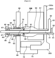
gas introduction structure 50 will be described with reference toFIG. 6. FIG. 6 is a diagram schematically illustrating a vertical cross-section of a configuration such as thegas introduction structure 50 provided in the vicinity of the furnace opening of thereaction tube 203 of the substrate processing apparatus 1 preferably used in the embodiments of the present disclosure. - As shown in
FIG. 6 , thegas introduction structure 50 is provided on theside wall 203s of the reaction tube (process vessel) 203. Thenozzle 30 is fixed to a mountingplate 68 by components such as afirst buffer ring 60, afirst seal ring 61, awasher 62, aunion screw 63, asleeve 64, asecond buffer ring 65, asecond seal ring 66, acap nut 67 and acoil spring 70 while being inserted into thegas introduction structure 50. Acooling block 72 capable of cooling the furnace opening of thereaction tube 203 and aholder 73 capable of holding the furnace opening of thereaction tube 203 are provided at the furnace opening of thereaction tube 203. - For example, the
sleeve 64 is of a cylindrical shape, and is made of a metal such as stainless steel (SUS) or a corrosion resistant material such as quartz (SiO2). A groove into which thefirst buffer ring 60, thefirst seal ring 61 and the like are fitted is provided at a front end (tip) of one end of the sleeve 64 (that is, an end of thesleeve 64 facing the gas introduction structure 50), and a male thread is cut on an outer periphery of the other end of the sleeve 64 (that is, an end of thesleeve 64 facing the cap nut 67). - The
union screw 63 is of a cylindrical shape, and is made of a metal such as stainless steel (SUS). A male screw is cut on an outer periphery of a right portion of theunion screw 63, and is screwed into a screw hole (not shown) provided in the mountingplate 68 made of a metal such as stainless steel (SUS). An outer periphery of a left portion of theunion screw 63 is of a hexagonal nut shape. By screwing theunion screw 63 into the mountingplate 68, thecoil spring 70 is urged, and a right end of thesleeve 64 is pressed against a left wall surface of thegas introduction structure 50 via thefirst seal ring 61. - The first seal ring (also simply referred to as an "O-ring") 61 is made of a fluororesin such as polytetrafluoroethylene (PTFE), and is of a ring shape. The
first seal ring 61 is configured to seal a gap between the front end of the sleeve 64 (that is, a right end of the sleeve 64) and the front end of the gas introduction structure 50 (that is, the left wall surface of the gas introduction structure 50). - The second seal ring (also simply referred to as an "O-ring") 66 is made of a fluororesin such as polytetrafluoroethylene (PTFE), and is of a ring shape. The
second seal ring 66 is configured to seal a gap between the other end of the sleeve 64 (that is, a left end of the sleeve 64) and an outer peripheral surface of thenozzle 30. - Each of the
first buffer ring 60 and thesecond buffer ring 65 is made of a fluororesin such as polytetrafluoroethylene (PTFE), and is used to prevent excessive deformation of the seal rings 61 and 66. - The
washer 62 is made of a metal such as stainless steel (SUS), and is provided between theunion screw 63 and thesleeve 64 and between thecoil spring 70 and theunion screw 63. Thewasher 62 is used to reduce friction. - The
cap nut 67 is made of a metal such as stainless steel (SUS), is screwed on the outer periphery of the left end of thesleeve 64, sandwiches thesecond seal ring 66 between thesleeve 64 and thecap nut 67. With thesecond seal ring 66 inserted between thesleeve 64 and thecap nut 67, thecap nut 67 is used to press thesecond seal ring 66 against thesleeve 64 and thenozzle 30. - Thus, the
nozzle 30 is supported by thesleeve 64 that is not rigidly joined to the mountingplate 68. Therefore, even when an assembly dimensional tolerance between thegas introduction structure 50 and the mountingplate 68 is large, it is possible to install thenozzle 30 without being damaged, and it is also possible to slightly adjust an angle of thenozzle 30. - The
nozzle 30 may be attached to the reaction tube (process vessel) 203 by performing the following steps. - The worker inserts the
nozzle 30 into thereaction tube 203 through the furnace opening provided at a lower portion of thereaction tube 203. Then, when inserting the firststraight portion 31 of thenozzle 30 into thegas introduction structure 50, the secondstraight portion 32 of thenozzle 30 is inserted into thegroove 41 until the secondstraight portion 32 of thenozzle 30 comes into contact with the bottom portion of thegroove 41 of the fixing block 40 (that is, the outerperipheral end 41e of thegroove 41 of the fixing block 40). In such a state, the worker can take his or her hand off thenozzle 30 without detaching, tilting or damaging thenozzle 30. - Then, the worker puts his or her hand inward through the furnace opening of the
reaction tube 203, inserts therestriction plate 45 into thewidth expanding portion 43, and inserts thefastening plate 55 into thegroove 53. - The worker properly tightens the
union screw 63 and thecap nut 67 such that thenozzle 30 is airtightly installed to thegas introduction structure 50. - When removing the
nozzle 30 from thereaction tube 203, it is possible to remove thenozzle 30 from thereaction tube 203 by performing the step 1), the step 2) and the step 3) described above in an order reverse to that of attaching thenozzle 30 to thereaction tube 203. That is, theunion screw 63 and thecap nut 67 are loosened, then therestriction plate 45 and thefastening plate 55 are removed, and then the firststraight portion 31 of thenozzle 30 is pulled out from thegas introduction structure 50. Then, thenozzle 30 is taken out from the furnace opening of thereaction tube 203 to the outside of thereaction tube 203. - By attaching the
nozzle 30 to thereaction tube 203 as described above, it is possible to connect and fix thenozzle 30 made of quartz to thereaction tube 203 made of quartz while preventing thenozzle 30 constituting the firstgas supply pipe 232a from collapsing in thereaction tube 203. Further, it is also possible to evaluate various nozzles by replacing thenozzle 30 in thereaction tube 203 with another nozzle. - Subsequently, a
controller 121 configured to control operations of components constituting the substrate processing apparatus 1 will be described with reference toFIG. 7. FIG. 7 is a block diagram schematically illustrating a configuration of thecontroller 121 and related components of the substrate processing apparatus 1 preferably used in the embodiments of the present disclosure. - As shown in
FIG. 7 , the substrate processing apparatus 1 includes thecontroller 121 configured to control the operations of the components constituting the substrate processing apparatus 1. For example, thecontroller 121 serving as a control structure is constituted by a computer including a CPU (Central Processing Unit) 121a, a RAM (Random Access Memory) 121b, amemory 121c and an I/O port 121d. TheRAM 121b, thememory 121c and the I/O port 121d may exchange data with theCPU 121a through aninternal bus 121e. For example, an input/output device 122 constituted by a component such as a touch panel is connected to thecontroller 121. - For example, the
memory 121c is configured by a component such as a flash memory and a hard disk drive (HDD). For example, a control program configured to control the operations of the substrate processing apparatus 1 or a process recipe containing information on sequences and conditions of the substrate processing described later may be readably stored in thememory 121c. The process recipe is obtained by combining steps (sequences) of the substrate processing described later such that thecontroller 121 can execute the steps to acquire a predetermined result, and functions as a program. Hereinafter, the process recipe and the control program may be collectively or individually referred to as a "program". In addition, the process recipe may also be simply referred to as a "recipe". Thus, in the present specification, the term "program" may refer to the recipe alone, may refer to the control program alone, or may refer to both of the recipe and the control program. TheRAM 121b functions as a memory area where a program or data read by theCPU 121a is temporarily stored. - The I/
O port 121d is connected to the above-described components such as the MFCs 241a and 241b, thevalves gas generator 250a, thepressure sensor 245, theAPC valve 244, thevacuum pump 246, theheater power supply 210, thetemperature sensor 263, the sidewall temperature sensors rotator 267 and theboat elevator 115. The gas supply pipe temperature sensor is a pipe temperature sensor configured to measure a temperature of each of thegas supply pipes exhaust pipe 231. - The
CPU 121a is configured to read the control program from thememory 121c and execute the read control program. In addition, theCPU 121a is configured to read the recipe from thememory 121c in accordance with an operation command inputted from the input/output device 122. In accordance with the contents of the read recipe, theCPU 121a may be configured to be capable of controlling various operations such as a gas generating operation of thegas generator 250a, flow rate adjusting operations for various gases by theMFCs valves APC valve 244 based on thepressure sensor 245, a start and stop of thevacuum pump 246, an adjusting operation of an amount of the electric power supplied from theheater power supply 210 to theheaters temperature sensor 263, the sidewall temperature sensors boat 217 by therotator 267 and an elevating and lowering operation of theboat 217 by theboat elevator 115. The cap heater is provided under theseal cap 219, and is a heating structure used for heating theseal cap 219. - The
controller 121 may be embodied by installing the above-described program stored in anexternal memory 123 into the computer. For example, theexternal memory 123 may include a magnetic disk such as a hard disk drive (HDD), an optical disk such as a CD, a magneto-optical disk such as an MO and a semiconductor memory such as a USB memory. Thememory 121c or theexternal memory 123 may be embodied by a non-transitory computer readable recording medium. Hereafter, thememory 121c and theexternal memory 123 may be collectively or individually referred to as a "recording medium". In the present specification, the term "recording medium" may refer to thememory 121c alone, may refer to theexternal memory 123 alone, or may refer to both of thememory 121c and theexternal memory 123. In addition, instead of theexternal memory 123, a communication structure such as the Internet and a dedicated line may be used for providing the program to the computer. - Subsequently, an example of the substrate processing performed as a part of a manufacturing process of a semiconductor device by using the substrate processing apparatus 1 will be described with reference to
FIG. 8. FIG. 8 is a flow chart schematically illustrating an exemplary sequence of the substrate processing preferably used in the embodiments of the present disclosure. In the following descriptions, the operations of the components constituting the substrate processing apparatus 1 are controlled by thecontroller 121. - For example, a film containing a silazane bond (-Si-N-) or a siloxane bond (-O-Si-O-) (that is, a polysilazane film or a siloxane polymer) is formed on a surface of the substrate (that is, the wafer 200) to be subject to a predetermined process in the substrate processing. The film such as the polysilazane film and a siloxane polymer may often be formed by using a coating method, and may also be referred to as a "SOD" (spin-on dielectric) or "SOG" (Spin-on Glass). For example, the polysilazane film contains nitrogen (N) and hydrogen (H) in addition to silicon (Si). The polysilazane film may further contain carbon (C) and other impurities in some cases. According to the substrate processing, by supplying the vaporized gas of the first oxidizing agent to the polysilazane film formed on the
wafer 200 under a relatively low temperature condition, it is possible to modify (or oxidize) the polysilazane film. - The
wafers 200 with the polysilazane film formed on the surfaces thereof are loaded (charged) into theboat 217. After theboat 217 is charged with thewafers 200, theboat 217 accommodating thewafers 200 is elevated by theboat elevator 115 and loaded into theprocess chamber 201 as shown inFIG. 1 . With theboat 217 loaded, theseal cap 219 seals the lower end opening of thereaction tube 203 via an O-ring. - The
vacuum pump 246 vacuum-exhausts the inner atmosphere of the process chamber 201 (that is, a space in which thewafers 200 are accommodated) until the inner pressure of theprocess chamber 201 reaches and is maintained at a predetermined pressure (modification pressure). Further, thereaction tube 203, thewafers 200 accommodated in theprocess chamber 201, theseal cap 219 and the like are heated by theheaters - When heating the
reaction tube 203, thewafers 200 accommodated in theprocess chamber 201, theseal cap 219 and the like, a state of electric conduction from theheater power supply 210 to theheater 207 is feedback-controlled based on the temperature information detected by thetemperature sensor 263 such that a temperature of thewafer 200 accommodated in the region A reaches and is maintained at a predetermined temperature. - Further, the state of electric conduction from the
heater power supply 210 to theheater 208 is feedback-controlled based on the temperature information detected by the temperature sensors (that is, the sidewall temperature sensors heater 208 such that a temperature of the side wall of the furnace opening of thereaction tube 203, a temperature of the firstgas supply pipe 232a, a temperature of the temperaturesensor protection pipe 263a and a temperature of theexhaust pipe 231 reach and are maintained at predetermined temperatures, respectively, or such that predetermined temperature distributions can be obtained with respect to the temperatures described above, respectively. - The state of electric conduction from the
heater power supply 210 to each of theheaters wafer 200 is completed. Further, therotator 267 starts to rotate thewafer 200. Until at least the processing of thewafer 200 is completed, thevacuum pump 246 continuously vacuum-exhausts the inner atmosphere of theprocess chamber 201, theheater 207 continuously heats thewafer 200 and therotator 267 continuously rotates thewafer 200. - Subsequently, a supply of the source material in the liquid state (that is, the first oxidizing agent) and a supply of the carrier gas to the
gas generator 250a are started, and the vaporized gas of the first oxidizing agent is generated by thegas generator 250a. After an amount and a concentration of the vaporized gas are stabilized, thevalves process chamber 201 through the gas supply holes of thegas supply pipes MFCs process chamber 201 are exhausted through theexhaust pipe 231. When supplying the vaporized gas and the second oxidizing agent, an oxidation reaction occurs on the surface of thewafer 200. Thereby, the polysilazane film on thewafer 200 is modified into a silicon oxide film (also referred to as a "SiO film"). - After a predetermined time has elapsed and the polysilazane film is completely modified into the SiO film, the
valve 243a is closed to stop the supply of the vaporized gas into theprocess chamber 201. - For example, process conditions of the modification step S3 are as follows.
- The concentration of the first oxidizing agent serving as the source material in the liquid state: from 20 % to 40 %, preferably from 25 % to 35 %;
- Vaporization conditions for the source material in the liquid state: heated to 120 °C to 200 °C under approximately atmospheric pressure;
- The modification pressure: from 700 hPa to 1,000 hPa (one among the atmospheric pressure, a slightly decompressed pressure or a slightly compressed pressure); and
- The temperature of the wafer 200: from 70 °C to 110 °C, preferably from 70 °C to 80 °C.
- Under the temperature conditions described above, the vaporized gas supplied into the
process chamber 201 may be re-liquefied in theprocess chamber 201, and the liquid generated by the re-liquefaction of the vaporized gas may be stagnant around the furnace opening such as the upper surface of theseal cap 219. In particular, a local low temperature region as described above may occur in components such as the side wall of the furnace opening, the firstgas supply pipe 232a in theprocess chamber 201 and the temperaturesensor protection pipe 263a, and the vaporized gas may be easily re-liquefied by contacting the local low temperature region. - According to the present embodiments, by controlling the
heater 208 configured as described above, it is possible to uniformly heat the components such as the side wall of the furnace opening of thereaction tube 203, and it is also possible to prevent the local low temperature region from occurring. According to the present embodiments, in order to prevent the re-liquefaction of the vaporized gas, a temperature control is performed so that there exists no region whose temperature is lower than a predetermined temperature (first lower limit temperature) on the components such as the side wall around the furnace opening of thereaction tube 203. The first lower limit temperature may vary depending on conditions such as the concentration of the vaporized gas, but may be set to, for example, 80 °C or higher under the process conditions described above. - When the modification step S3 is completed, the
heater 207 is controlled to heat thewafer 200 to a temperature higher than the modification temperature described above. By maintaining the temperature higher than the modification temperature, it is possible to gently dry thewafer 200 and an inside of theprocess chamber 201. - After the drying step S4 is completed, the inside of the
process chamber 201 is vacuum-exhausted. Thereafter, the inner pressure of theprocess chamber 201 is returned to the atmospheric pressure. After a predetermined time has elapsed, the inner temperature of theprocess chamber 201 is lowered to a predetermined temperature at which thewafer 200 can be unloaded. - The
seal cap 219 is lowered by theboat elevator 115, and the lower end opening of thereaction tube 203 is opened. Then, theboat 217 accommodating thewafers 200 processed according to the steps described above is unloaded (transferred) out of thereaction tube 203 through the lower end opening of thereaction tube 203. Thereafter, thewafers 200 processed according to the steps described above are unloaded (discharged) out of theboat 217. - The invention may be summarized as follows: There is provided a technique capable of connecting and fixing a nozzle to a reaction tube while preventing the nozzle from collapsing. According to one aspect thereof, there is provided a substrate processing apparatus including: a gas introduction structure made of a non-metallic material, penetrating a side wall of a process vessel and integrated with the side wall as a single structure, wherein a front end thereof protrudes into the process vessel; a nozzle made of a non-metallic material and including: a first straight portion inserted into the gas introduction structure and fluidically communicating with the gas introduction structure; and a second straight portion fluidically communicating with the first straight portion and extending along an inner wall of the process vessel; and a fixing block provided at an inner side of the side wall of the process vessel and above the gas introduction structure, wherein the fixing block is provided with a groove in which the nozzle is capable of being moved in a radial direction of the process vessel.
- While the technique of the present disclosure is described in detail by way of the embodiments described above, the technique of the present disclosure is not limited thereto. The technique of the present disclosure may be modified in various ways without departing from the scope thereof.
[Description of Reference Numerals] 1 substrate processing apparatus 30 nozzle 40 fixing block 45 restriction plate 55 fastening plate 203 reaction tube 232a, 232b gas supply pipes
Claims (15)
- A substrate processing apparatus comprising:a gas introduction structure made of a non-metallic material, penetrating a side wall of a process vessel and integrated with the side wall as a single structure, wherein a front end thereof protrudes into the process vessel;a nozzle made of a non-metallic material and comprising:a first straight portion inserted into the gas introduction structure and fluidically communicating with the gas introduction structure; anda second straight portion fluidically communicating with the first straight portion and extending along an inner wall of the process vessel; anda fixing block provided at an inner side of the side wall of the process vessel and above the gas introduction structure, wherein the fixing block is provided with a groove in which the nozzle is capable of being moved in a radial direction of the process vessel.
- The substrate processing apparatus of claim 1, wherein an end of the gas introduction structure at an inner side of the process vessel extends further into the process vessel than the nozzle, and a fastener is inserted into the end of the gas introduction structure at the inner side of the process vessel.
- The substrate processing apparatus of claim 1 and/or 2, wherein the fixing block is integrally formed with the process vessel as a single structure, and the groove is open toward an inner side of the process vessel.
- The substrate processing apparatus of any one or more of claims 1 to 3, further comprising a restrictor made of a non-metallic material and configured to restrict a movement of the nozzle,
wherein the groove is provided with a width expanding portion, and the restrictor is fitted in the width expanding portion with the nozzle arranged on a bottom portion of the groove located closer to a bottom of the groove than the width expanding portion. - The substrate processing apparatus of any one or more of claims 1 to 4, wherein the fixing block is provided at a height within a heat insulating region of the process vessel or a height lower than a vertical center of the nozzle.
- The substrate processing apparatus of any one or more of claims 1 to 5, wherein the fixing block is provided at a distance of 40 cm or less from a furnace opening of the process vessel.
- The substrate processing apparatus of any one or more of claims 4 to 6, wherein the width expanding portion is configured so as not to penetrate a lower end of the fixing block.
- The substrate processing apparatus of any one or more of claims 4 to 7, wherein a horizontal position of the nozzle is determined by being interposed between an outer peripheral end of the groove and the restrictor.
- The substrate processing apparatus of any one or more of claims 1 to 8, wherein the gas introduction structure is provided with an introduction tube whose inner diameter substantially corresponds to an outer diameter of the nozzle, and a notch of a U-shape whose width substantially corresponds to the inner diameter of the introduction tube is provided at a front end and an upper end of the introduction tube.
- The substrate processing apparatus of claim 9, wherein a lower end of the nozzle is of a shape corresponding to a surface of the gas introduction structure facing the lower end of the nozzle, and is provided with an opening fluidically communicating between an inside of the nozzle and the introduction tube.
- The substrate processing apparatus of any one or more of claims 1 to 10, wherein a lower end of the nozzle is of a shape corresponding to a surface of the gas introduction structure facing the lower end of the nozzle, and is provided with an opening fluidically communicating between an inside of the nozzle and the gas introduction structure.
- The substrate processing apparatus of any one or more of claims 1 to 11, wherein the nozzle is provided with a discharge hole through which at least one selected from the group consisting of vaporized hydrogen peroxide, water and ozone is supplied into the process vessel.
- A use of a substrate processing apparatus for a substrate processing, wherein the substrate processing apparatus comprises:a gas introduction structure made of a non-metallic material, penetrating a side wall of a process vessel and integrated with the side wall as a single structure, wherein a front end thereof protrudes into the process vessel;a nozzle made of a non-metallic material and comprising:a first straight portion inserted into the gas introduction structure and fluidically communicating with the gas introduction structure; anda second straight portion fluidically communicating with the first straight portion and extending along an inner wall of the process vessel; anda fixing block provided at an inner side of the side wall of the process vessel and above the gas introduction structure, wherein the fixing block is provided with a groove in which the nozzle is capable of being moved in a radial direction of the process vessel.
- A method of manufacturing a semiconductor device, comprising:(a) loading a substrate into a process vessel of a substrate processing apparatus; and(b) processing the substrate,wherein the substrate processing apparatus comprises:
a gas introduction structure made of a non-metallic material, penetrating a side wall of a process vessel, and integrated with the side wall of the process vessel as a single structure, wherein a front end thereof protrudes into the process vessel;
a nozzle made of a non-metallic material and comprising:a first straight portion inserted into the gas introduction structure and fluidically communicating with the gas introduction structure; anda second straight portion fluidically communicating with the first straight portion and extending along an inner wall of the process vessel; anda fixing block provided at an inner side of the side wall of the process vessel and above the gas introduction structure, wherein the fixing block is provided with a groove in which the nozzle is capable of being moved in a radial direction of the process vessel. - A computer program product comprising an instruction that causes, by a computer, a substrate processing apparatus to perform the method of manufacturing a semiconductor device of claim 14 when a program is executed by the computer of the substrate processing apparatus.
Applications Claiming Priority (1)
| Application Number | Priority Date | Filing Date | Title |
|---|---|---|---|
| JP2021156062A JP7281519B2 (en) | 2021-09-24 | 2021-09-24 | SUBSTRATE PROCESSING APPARATUS, SEMICONDUCTOR DEVICE MANUFACTURING METHOD, AND PROCESSING CONTAINER |
Publications (2)
| Publication Number | Publication Date |
|---|---|
| EP4156235A1 true EP4156235A1 (en) | 2023-03-29 |
| EP4156235B1 EP4156235B1 (en) | 2024-02-14 |
Family
ID=83319012
Family Applications (1)
| Application Number | Title | Priority Date | Filing Date |
|---|---|---|---|
| EP22191301.5A Active EP4156235B1 (en) | 2021-09-24 | 2022-08-19 | Substrate processing apparatus, use of substrate processing apparatus, method of manufacturing semiconductor device and computer program product |
Country Status (6)
| Country | Link |
|---|---|
| US (1) | US12338529B2 (en) |
| EP (1) | EP4156235B1 (en) |
| JP (1) | JP7281519B2 (en) |
| KR (1) | KR102685900B1 (en) |
| CN (1) | CN115938977A (en) |
| TW (1) | TWI836550B (en) |
Citations (5)
| Publication number | Priority date | Publication date | Assignee | Title |
|---|---|---|---|---|
| JPH0997767A (en) | 1995-09-28 | 1997-04-08 | Kokusai Electric Co Ltd | Vertical furnace for semiconductor manufacturing equipment |
| US20090205783A1 (en) * | 2008-02-20 | 2009-08-20 | Hitachi-Kokusai Electric Inc. | Substrate processing apparatus |
| US7883076B2 (en) * | 2005-11-15 | 2011-02-08 | Tokyo Electron Limited | Semiconductor processing system and vaporizer |
| WO2018179157A1 (en) | 2017-03-29 | 2018-10-04 | 株式会社Kokusai Electric | Substrate processing device, heater unit, and semiconductor device manufacturing method |
| US20200149159A1 (en) * | 2017-09-25 | 2020-05-14 | Kokusai Electric Corporation | Substrate processing apparatus, quartz reaction tube and method of manufacturing semiconductor device |
Family Cites Families (21)
| Publication number | Priority date | Publication date | Assignee | Title |
|---|---|---|---|---|
| JP2002299273A (en) * | 2001-04-04 | 2002-10-11 | Sharp Corp | Heat treatment equipment for semiconductor substrates |
| US8070880B2 (en) * | 2007-10-22 | 2011-12-06 | Hitachi Kokusai Electric, Inc. | Substrate processing apparatus |
| JP2009224504A (en) * | 2008-03-14 | 2009-10-01 | Hitachi Kokusai Electric Inc | Substrate processing apparatus |
| JP2010034283A (en) * | 2008-07-29 | 2010-02-12 | Hitachi Kokusai Electric Inc | Substrate processing apparatus |
| JP2010056249A (en) * | 2008-08-27 | 2010-03-11 | Hitachi Kokusai Electric Inc | Substrate processing apparatus, and method of manufacturing semiconductor device |
| JP2010093131A (en) | 2008-10-09 | 2010-04-22 | Hitachi Kokusai Electric Inc | Substrate processing apparatus |
| JP2009124161A (en) * | 2008-12-26 | 2009-06-04 | Tokyo Electron Ltd | Heat treatment equipment |
| JP5247528B2 (en) * | 2009-02-23 | 2013-07-24 | 株式会社日立国際電気 | Substrate processing apparatus, semiconductor device manufacturing method, substrate processing method, and gas introducing means |
| US20100326357A1 (en) * | 2009-06-30 | 2010-12-30 | Wei-Hung Huang | Nozzle and furnace having the same |
| JP2011114069A (en) * | 2009-11-25 | 2011-06-09 | Hitachi Kokusai Electric Inc | Vertical heat treatment device |
| JP2012151386A (en) * | 2011-01-21 | 2012-08-09 | Hitachi Kokusai Electric Inc | Nozzle attachment method |
| JP2013187459A (en) | 2012-03-09 | 2013-09-19 | Hitachi Kokusai Electric Inc | Substrate processing apparatus |
| JP6145279B2 (en) * | 2013-02-06 | 2017-06-07 | 東京エレクトロン株式会社 | Gas introduction pipe connection structure and heat treatment apparatus using the same |
| JP2014165429A (en) * | 2013-02-27 | 2014-09-08 | Tokyo Electron Ltd | Injector mounting device and injector mounting method |
| JP6430870B2 (en) * | 2015-03-20 | 2018-11-28 | 東京エレクトロン株式会社 | Clamp device, substrate carry-in / out device using the same, and substrate processing apparatus |
| JP6602230B2 (en) | 2016-02-29 | 2019-11-06 | 東京エレクトロン株式会社 | Quartz tube holding structure and heat treatment apparatus using the same |
| JP6550029B2 (en) * | 2016-09-28 | 2019-07-24 | 株式会社Kokusai Electric | Substrate processing apparatus, nozzle base and method of manufacturing semiconductor device |
| CN110121764B (en) * | 2017-02-15 | 2024-10-25 | 株式会社国际电气 | Substrate processing device, reaction tube, semiconductor device manufacturing method and program |
| JP6916766B2 (en) * | 2018-08-27 | 2021-08-11 | 株式会社Kokusai Electric | Manufacturing method of substrate processing equipment and semiconductor equipment |
| JP6749954B2 (en) * | 2018-02-20 | 2020-09-02 | 株式会社Kokusai Electric | Substrate processing apparatus, semiconductor device manufacturing method, and program |
| TWI733342B (en) | 2019-03-20 | 2021-07-11 | 日商國際電氣股份有限公司 | Gas supply unit, substrate processing device and method for manufacturing semiconductor device |
-
2021
- 2021-09-24 JP JP2021156062A patent/JP7281519B2/en active Active
-
2022
- 2022-08-04 CN CN202210931503.5A patent/CN115938977A/en active Pending
- 2022-08-09 KR KR1020220099278A patent/KR102685900B1/en active Active
- 2022-08-10 TW TW111130026A patent/TWI836550B/en active
- 2022-08-11 US US17/885,636 patent/US12338529B2/en active Active
- 2022-08-19 EP EP22191301.5A patent/EP4156235B1/en active Active
Patent Citations (5)
| Publication number | Priority date | Publication date | Assignee | Title |
|---|---|---|---|---|
| JPH0997767A (en) | 1995-09-28 | 1997-04-08 | Kokusai Electric Co Ltd | Vertical furnace for semiconductor manufacturing equipment |
| US7883076B2 (en) * | 2005-11-15 | 2011-02-08 | Tokyo Electron Limited | Semiconductor processing system and vaporizer |
| US20090205783A1 (en) * | 2008-02-20 | 2009-08-20 | Hitachi-Kokusai Electric Inc. | Substrate processing apparatus |
| WO2018179157A1 (en) | 2017-03-29 | 2018-10-04 | 株式会社Kokusai Electric | Substrate processing device, heater unit, and semiconductor device manufacturing method |
| US20200149159A1 (en) * | 2017-09-25 | 2020-05-14 | Kokusai Electric Corporation | Substrate processing apparatus, quartz reaction tube and method of manufacturing semiconductor device |
Also Published As
| Publication number | Publication date |
|---|---|
| US12338529B2 (en) | 2025-06-24 |
| KR20230043676A (en) | 2023-03-31 |
| EP4156235B1 (en) | 2024-02-14 |
| CN115938977A (en) | 2023-04-07 |
| US20230096080A1 (en) | 2023-03-30 |
| JP7281519B2 (en) | 2023-05-25 |
| TW202322244A (en) | 2023-06-01 |
| TWI836550B (en) | 2024-03-21 |
| KR102685900B1 (en) | 2024-07-16 |
| JP2023047121A (en) | 2023-04-05 |
Similar Documents
| Publication | Publication Date | Title |
|---|---|---|
| US12087598B2 (en) | Substrate processing apparatus | |
| US20160076149A1 (en) | Substrate processing apparatus, method of manufacturing semiconductor device and furnace lid | |
| US9587313B2 (en) | Substrate processing apparatus, method of manufacturing semiconductor device, and non-transitory computer-readable recording medium | |
| KR102074668B1 (en) | Substrate processing apparatus, quartz reaction tube, cleaning method and program | |
| CN101800162A (en) | Component for vertical heat processing apparatus, vertical heat processing apparatus and heat-insulating cylinder | |
| US9793112B2 (en) | Method of manufacturing semiconductor device and non-transitory computer-readable recording medium | |
| CN108531889A (en) | Gas supply device, method for supplying gas and film build method | |
| US20230041284A1 (en) | Substrate processing apparatus, method of manufacturing semiconductor device and non-transitory computer-readable recording medium | |
| US9502239B2 (en) | Substrate processing method, substrate processing apparatus, method of manufacturing semiconductor device and non-transitory computer-readable recording medium | |
| US11035037B2 (en) | Substrate processing apparatus and metal member | |
| CN108531888A (en) | Gas supply device, method for supplying gas and film build method | |
| US20090064765A1 (en) | Method of Manufacturing Semiconductor Device | |
| US20190003047A1 (en) | Vaporizer and Substrate Processing Apparatus | |
| KR102696214B1 (en) | Vaporizer, processing apparatus, processing apparatus method, method of manufacturing semiconductor device and cleaning method | |
| US20230343614A1 (en) | Substrate processing apparatus, substrate holder, method of manufacturing semiconductor device, and recording medium | |
| EP4156235B1 (en) | Substrate processing apparatus, use of substrate processing apparatus, method of manufacturing semiconductor device and computer program product | |
| CN101256957A (en) | Heat treatment method and apparatus for semiconductor processing | |
| JP4086054B2 (en) | Process for oxidizing object, oxidation apparatus and storage medium | |
| CN108389770A (en) | Ozone gas heating mechanism, substrate processing device, and substrate processing method | |
| WO2018179507A1 (en) | Semiconductor device manufacturing method, substrate processing device, and program | |
| KR20260029268A (en) | Adapter, substrate processing device, substrate processing method, semiconductor device manufacturing method and program | |
| WO2018020590A1 (en) | Substrate treating device, method for manufacturing semiconductor device, and program |
Legal Events
| Date | Code | Title | Description |
|---|---|---|---|
| PUAI | Public reference made under article 153(3) epc to a published international application that has entered the european phase |
Free format text: ORIGINAL CODE: 0009012 |
|
| STAA | Information on the status of an ep patent application or granted ep patent |
Free format text: STATUS: THE APPLICATION HAS BEEN PUBLISHED |
|
| STAA | Information on the status of an ep patent application or granted ep patent |
Free format text: STATUS: REQUEST FOR EXAMINATION WAS MADE |
|
| AK | Designated contracting states |
Kind code of ref document: A1 Designated state(s): AL AT BE BG CH CY CZ DE DK EE ES FI FR GB GR HR HU IE IS IT LI LT LU LV MC MK MT NL NO PL PT RO RS SE SI SK SM TR |
|
| 17P | Request for examination filed |
Effective date: 20230224 |
|
| RBV | Designated contracting states (corrected) |
Designated state(s): AL AT BE BG CH CY CZ DE DK EE ES FI FR GB GR HR HU IE IS IT LI LT LU LV MC MK MT NL NO PL PT RO RS SE SI SK SM TR |
|
| GRAP | Despatch of communication of intention to grant a patent |
Free format text: ORIGINAL CODE: EPIDOSNIGR1 |
|
| STAA | Information on the status of an ep patent application or granted ep patent |
Free format text: STATUS: GRANT OF PATENT IS INTENDED |
|
| INTG | Intention to grant announced |
Effective date: 20230831 |
|
| P01 | Opt-out of the competence of the unified patent court (upc) registered |
Effective date: 20230817 |
|
| RIN1 | Information on inventor provided before grant (corrected) |
Inventor name: NAKASHIMA, SEIYO Inventor name: MORITA, SHINYA |
|
| GRAS | Grant fee paid |
Free format text: ORIGINAL CODE: EPIDOSNIGR3 |
|
| GRAA | (expected) grant |
Free format text: ORIGINAL CODE: 0009210 |
|
| STAA | Information on the status of an ep patent application or granted ep patent |
Free format text: STATUS: THE PATENT HAS BEEN GRANTED |
|
| AK | Designated contracting states |
Kind code of ref document: B1 Designated state(s): AL AT BE BG CH CY CZ DE DK EE ES FI FR GB GR HR HU IE IS IT LI LT LU LV MC MK MT NL NO PL PT RO RS SE SI SK SM TR |
|
| REG | Reference to a national code |
Ref country code: GB Ref legal event code: FG4D |
|
| REG | Reference to a national code |
Ref country code: CH Ref legal event code: EP |
|
| REG | Reference to a national code |
Ref country code: DE Ref legal event code: R096 Ref document number: 602022001947 Country of ref document: DE |
|
| REG | Reference to a national code |
Ref country code: IE Ref legal event code: FG4D |
|
| REG | Reference to a national code |
Ref country code: LT Ref legal event code: MG9D |
|
| REG | Reference to a national code |
Ref country code: NL Ref legal event code: MP Effective date: 20240214 |
|
| PG25 | Lapsed in a contracting state [announced via postgrant information from national office to epo] |
Ref country code: IS Free format text: LAPSE BECAUSE OF FAILURE TO SUBMIT A TRANSLATION OF THE DESCRIPTION OR TO PAY THE FEE WITHIN THE PRESCRIBED TIME-LIMIT Effective date: 20240614 |
|
| PG25 | Lapsed in a contracting state [announced via postgrant information from national office to epo] |
Ref country code: LT Free format text: LAPSE BECAUSE OF FAILURE TO SUBMIT A TRANSLATION OF THE DESCRIPTION OR TO PAY THE FEE WITHIN THE PRESCRIBED TIME-LIMIT Effective date: 20240214 |
|
| PG25 | Lapsed in a contracting state [announced via postgrant information from national office to epo] |
Ref country code: GR Free format text: LAPSE BECAUSE OF FAILURE TO SUBMIT A TRANSLATION OF THE DESCRIPTION OR TO PAY THE FEE WITHIN THE PRESCRIBED TIME-LIMIT Effective date: 20240515 |
|
| REG | Reference to a national code |
Ref country code: AT Ref legal event code: MK05 Ref document number: 1657794 Country of ref document: AT Kind code of ref document: T Effective date: 20240214 |
|
| PG25 | Lapsed in a contracting state [announced via postgrant information from national office to epo] |
Ref country code: NL Free format text: LAPSE BECAUSE OF FAILURE TO SUBMIT A TRANSLATION OF THE DESCRIPTION OR TO PAY THE FEE WITHIN THE PRESCRIBED TIME-LIMIT Effective date: 20240214 Ref country code: HR Free format text: LAPSE BECAUSE OF FAILURE TO SUBMIT A TRANSLATION OF THE DESCRIPTION OR TO PAY THE FEE WITHIN THE PRESCRIBED TIME-LIMIT Effective date: 20240214 Ref country code: RS Free format text: LAPSE BECAUSE OF FAILURE TO SUBMIT A TRANSLATION OF THE DESCRIPTION OR TO PAY THE FEE WITHIN THE PRESCRIBED TIME-LIMIT Effective date: 20240514 |
|
| PG25 | Lapsed in a contracting state [announced via postgrant information from national office to epo] |
Ref country code: ES Free format text: LAPSE BECAUSE OF FAILURE TO SUBMIT A TRANSLATION OF THE DESCRIPTION OR TO PAY THE FEE WITHIN THE PRESCRIBED TIME-LIMIT Effective date: 20240214 |
|
| PG25 | Lapsed in a contracting state [announced via postgrant information from national office to epo] |
Ref country code: AT Free format text: LAPSE BECAUSE OF FAILURE TO SUBMIT A TRANSLATION OF THE DESCRIPTION OR TO PAY THE FEE WITHIN THE PRESCRIBED TIME-LIMIT Effective date: 20240214 |
|
| PG25 | Lapsed in a contracting state [announced via postgrant information from national office to epo] |
Ref country code: RS Free format text: LAPSE BECAUSE OF FAILURE TO SUBMIT A TRANSLATION OF THE DESCRIPTION OR TO PAY THE FEE WITHIN THE PRESCRIBED TIME-LIMIT Effective date: 20240514 Ref country code: NO Free format text: LAPSE BECAUSE OF FAILURE TO SUBMIT A TRANSLATION OF THE DESCRIPTION OR TO PAY THE FEE WITHIN THE PRESCRIBED TIME-LIMIT Effective date: 20240514 Ref country code: NL Free format text: LAPSE BECAUSE OF FAILURE TO SUBMIT A TRANSLATION OF THE DESCRIPTION OR TO PAY THE FEE WITHIN THE PRESCRIBED TIME-LIMIT Effective date: 20240214 Ref country code: LT Free format text: LAPSE BECAUSE OF FAILURE TO SUBMIT A TRANSLATION OF THE DESCRIPTION OR TO PAY THE FEE WITHIN THE PRESCRIBED TIME-LIMIT Effective date: 20240214 Ref country code: IS Free format text: LAPSE BECAUSE OF FAILURE TO SUBMIT A TRANSLATION OF THE DESCRIPTION OR TO PAY THE FEE WITHIN THE PRESCRIBED TIME-LIMIT Effective date: 20240614 Ref country code: HR Free format text: LAPSE BECAUSE OF FAILURE TO SUBMIT A TRANSLATION OF THE DESCRIPTION OR TO PAY THE FEE WITHIN THE PRESCRIBED TIME-LIMIT Effective date: 20240214 Ref country code: GR Free format text: LAPSE BECAUSE OF FAILURE TO SUBMIT A TRANSLATION OF THE DESCRIPTION OR TO PAY THE FEE WITHIN THE PRESCRIBED TIME-LIMIT Effective date: 20240515 Ref country code: FI Free format text: LAPSE BECAUSE OF FAILURE TO SUBMIT A TRANSLATION OF THE DESCRIPTION OR TO PAY THE FEE WITHIN THE PRESCRIBED TIME-LIMIT Effective date: 20240214 Ref country code: ES Free format text: LAPSE BECAUSE OF FAILURE TO SUBMIT A TRANSLATION OF THE DESCRIPTION OR TO PAY THE FEE WITHIN THE PRESCRIBED TIME-LIMIT Effective date: 20240214 Ref country code: BG Free format text: LAPSE BECAUSE OF FAILURE TO SUBMIT A TRANSLATION OF THE DESCRIPTION OR TO PAY THE FEE WITHIN THE PRESCRIBED TIME-LIMIT Effective date: 20240214 Ref country code: AT Free format text: LAPSE BECAUSE OF FAILURE TO SUBMIT A TRANSLATION OF THE DESCRIPTION OR TO PAY THE FEE WITHIN THE PRESCRIBED TIME-LIMIT Effective date: 20240214 |
|
| PG25 | Lapsed in a contracting state [announced via postgrant information from national office to epo] |
Ref country code: PT Free format text: LAPSE BECAUSE OF FAILURE TO SUBMIT A TRANSLATION OF THE DESCRIPTION OR TO PAY THE FEE WITHIN THE PRESCRIBED TIME-LIMIT Effective date: 20240614 Ref country code: PL Free format text: LAPSE BECAUSE OF FAILURE TO SUBMIT A TRANSLATION OF THE DESCRIPTION OR TO PAY THE FEE WITHIN THE PRESCRIBED TIME-LIMIT Effective date: 20240214 |
|
| PG25 | Lapsed in a contracting state [announced via postgrant information from national office to epo] |
Ref country code: SE Free format text: LAPSE BECAUSE OF FAILURE TO SUBMIT A TRANSLATION OF THE DESCRIPTION OR TO PAY THE FEE WITHIN THE PRESCRIBED TIME-LIMIT Effective date: 20240214 Ref country code: PT Free format text: LAPSE BECAUSE OF FAILURE TO SUBMIT A TRANSLATION OF THE DESCRIPTION OR TO PAY THE FEE WITHIN THE PRESCRIBED TIME-LIMIT Effective date: 20240614 Ref country code: PL Free format text: LAPSE BECAUSE OF FAILURE TO SUBMIT A TRANSLATION OF THE DESCRIPTION OR TO PAY THE FEE WITHIN THE PRESCRIBED TIME-LIMIT Effective date: 20240214 Ref country code: LV Free format text: LAPSE BECAUSE OF FAILURE TO SUBMIT A TRANSLATION OF THE DESCRIPTION OR TO PAY THE FEE WITHIN THE PRESCRIBED TIME-LIMIT Effective date: 20240214 |
|
| PG25 | Lapsed in a contracting state [announced via postgrant information from national office to epo] |
Ref country code: DK Free format text: LAPSE BECAUSE OF FAILURE TO SUBMIT A TRANSLATION OF THE DESCRIPTION OR TO PAY THE FEE WITHIN THE PRESCRIBED TIME-LIMIT Effective date: 20240214 |
|
| PG25 | Lapsed in a contracting state [announced via postgrant information from national office to epo] |
Ref country code: SM Free format text: LAPSE BECAUSE OF FAILURE TO SUBMIT A TRANSLATION OF THE DESCRIPTION OR TO PAY THE FEE WITHIN THE PRESCRIBED TIME-LIMIT Effective date: 20240214 |
|
| PG25 | Lapsed in a contracting state [announced via postgrant information from national office to epo] |
Ref country code: EE Free format text: LAPSE BECAUSE OF FAILURE TO SUBMIT A TRANSLATION OF THE DESCRIPTION OR TO PAY THE FEE WITHIN THE PRESCRIBED TIME-LIMIT Effective date: 20240214 Ref country code: CZ Free format text: LAPSE BECAUSE OF FAILURE TO SUBMIT A TRANSLATION OF THE DESCRIPTION OR TO PAY THE FEE WITHIN THE PRESCRIBED TIME-LIMIT Effective date: 20240214 |
|
| PG25 | Lapsed in a contracting state [announced via postgrant information from national office to epo] |
Ref country code: SK Free format text: LAPSE BECAUSE OF FAILURE TO SUBMIT A TRANSLATION OF THE DESCRIPTION OR TO PAY THE FEE WITHIN THE PRESCRIBED TIME-LIMIT Effective date: 20240214 |
|
| PG25 | Lapsed in a contracting state [announced via postgrant information from national office to epo] |
Ref country code: SM Free format text: LAPSE BECAUSE OF FAILURE TO SUBMIT A TRANSLATION OF THE DESCRIPTION OR TO PAY THE FEE WITHIN THE PRESCRIBED TIME-LIMIT Effective date: 20240214 Ref country code: SK Free format text: LAPSE BECAUSE OF FAILURE TO SUBMIT A TRANSLATION OF THE DESCRIPTION OR TO PAY THE FEE WITHIN THE PRESCRIBED TIME-LIMIT Effective date: 20240214 Ref country code: RO Free format text: LAPSE BECAUSE OF FAILURE TO SUBMIT A TRANSLATION OF THE DESCRIPTION OR TO PAY THE FEE WITHIN THE PRESCRIBED TIME-LIMIT Effective date: 20240214 Ref country code: EE Free format text: LAPSE BECAUSE OF FAILURE TO SUBMIT A TRANSLATION OF THE DESCRIPTION OR TO PAY THE FEE WITHIN THE PRESCRIBED TIME-LIMIT Effective date: 20240214 Ref country code: DK Free format text: LAPSE BECAUSE OF FAILURE TO SUBMIT A TRANSLATION OF THE DESCRIPTION OR TO PAY THE FEE WITHIN THE PRESCRIBED TIME-LIMIT Effective date: 20240214 Ref country code: CZ Free format text: LAPSE BECAUSE OF FAILURE TO SUBMIT A TRANSLATION OF THE DESCRIPTION OR TO PAY THE FEE WITHIN THE PRESCRIBED TIME-LIMIT Effective date: 20240214 |
|
| REG | Reference to a national code |
Ref country code: DE Ref legal event code: R097 Ref document number: 602022001947 Country of ref document: DE |
|
| PG25 | Lapsed in a contracting state [announced via postgrant information from national office to epo] |
Ref country code: IT Free format text: LAPSE BECAUSE OF FAILURE TO SUBMIT A TRANSLATION OF THE DESCRIPTION OR TO PAY THE FEE WITHIN THE PRESCRIBED TIME-LIMIT Effective date: 20240214 |
|
| PLBE | No opposition filed within time limit |
Free format text: ORIGINAL CODE: 0009261 |
|
| STAA | Information on the status of an ep patent application or granted ep patent |
Free format text: STATUS: NO OPPOSITION FILED WITHIN TIME LIMIT |
|
| PG25 | Lapsed in a contracting state [announced via postgrant information from national office to epo] |
Ref country code: IT Free format text: LAPSE BECAUSE OF FAILURE TO SUBMIT A TRANSLATION OF THE DESCRIPTION OR TO PAY THE FEE WITHIN THE PRESCRIBED TIME-LIMIT Effective date: 20240214 |
|
| 26N | No opposition filed |
Effective date: 20241115 |
|
| PG25 | Lapsed in a contracting state [announced via postgrant information from national office to epo] |
Ref country code: LU Free format text: LAPSE BECAUSE OF NON-PAYMENT OF DUE FEES Effective date: 20240819 |
|
| PG25 | Lapsed in a contracting state [announced via postgrant information from national office to epo] |
Ref country code: MC Free format text: LAPSE BECAUSE OF FAILURE TO SUBMIT A TRANSLATION OF THE DESCRIPTION OR TO PAY THE FEE WITHIN THE PRESCRIBED TIME-LIMIT Effective date: 20240214 Ref country code: SI Free format text: LAPSE BECAUSE OF FAILURE TO SUBMIT A TRANSLATION OF THE DESCRIPTION OR TO PAY THE FEE WITHIN THE PRESCRIBED TIME-LIMIT Effective date: 20240214 |
|
| REG | Reference to a national code |
Ref country code: BE Ref legal event code: MM Effective date: 20240831 |
|
| PG25 | Lapsed in a contracting state [announced via postgrant information from national office to epo] |
Ref country code: BE Free format text: LAPSE BECAUSE OF NON-PAYMENT OF DUE FEES Effective date: 20240831 |
|
| PGFP | Annual fee paid to national office [announced via postgrant information from national office to epo] |
Ref country code: DE Payment date: 20250702 Year of fee payment: 4 |
|
| PGFP | Annual fee paid to national office [announced via postgrant information from national office to epo] |
Ref country code: FR Payment date: 20250703 Year of fee payment: 4 |
|
| PGFP | Annual fee paid to national office [announced via postgrant information from national office to epo] |
Ref country code: IE Payment date: 20250702 Year of fee payment: 4 |
|
| REG | Reference to a national code |
Ref country code: DE Ref legal event code: R079 Ref document number: 602022001947 Country of ref document: DE Free format text: PREVIOUS MAIN CLASS: H01L0021670000 Ipc: H10P0072000000 |
|
| PG25 | Lapsed in a contracting state [announced via postgrant information from national office to epo] |
Ref country code: CY Free format text: LAPSE BECAUSE OF FAILURE TO SUBMIT A TRANSLATION OF THE DESCRIPTION OR TO PAY THE FEE WITHIN THE PRESCRIBED TIME-LIMIT; INVALID AB INITIO Effective date: 20220819 |
|
| PG25 | Lapsed in a contracting state [announced via postgrant information from national office to epo] |
Ref country code: HU Free format text: LAPSE BECAUSE OF FAILURE TO SUBMIT A TRANSLATION OF THE DESCRIPTION OR TO PAY THE FEE WITHIN THE PRESCRIBED TIME-LIMIT; INVALID AB INITIO Effective date: 20220819 |
|
| REG | Reference to a national code |
Ref country code: CH Ref legal event code: H13 Free format text: ST27 STATUS EVENT CODE: U-0-0-H10-H13 (AS PROVIDED BY THE NATIONAL OFFICE) Effective date: 20260324 |
|
| PG25 | Lapsed in a contracting state [announced via postgrant information from national office to epo] |
Ref country code: CH Free format text: LAPSE BECAUSE OF NON-PAYMENT OF DUE FEES Effective date: 20250831 |