EP4156211A1 - Slim-type magnetic component - Google Patents
Slim-type magnetic component Download PDFInfo
- Publication number
- EP4156211A1 EP4156211A1 EP22198349.7A EP22198349A EP4156211A1 EP 4156211 A1 EP4156211 A1 EP 4156211A1 EP 22198349 A EP22198349 A EP 22198349A EP 4156211 A1 EP4156211 A1 EP 4156211A1
- Authority
- EP
- European Patent Office
- Prior art keywords
- magnetic component
- terminal
- secondary coil
- accommodation portion
- component according
- Prior art date
- Legal status (The legal status is an assumption and is not a legal conclusion. Google has not performed a legal analysis and makes no representation as to the accuracy of the status listed.)
- Granted
Links
Images




Classifications
-
- H—ELECTRICITY
- H01—ELECTRIC ELEMENTS
- H01F—MAGNETS; INDUCTANCES; TRANSFORMERS; SELECTION OF MATERIALS FOR THEIR MAGNETIC PROPERTIES
- H01F27/00—Details of transformers or inductances, in general
- H01F27/28—Coils; Windings; Conductive connections
- H01F27/29—Terminals; Tapping arrangements for signal inductances
-
- H—ELECTRICITY
- H01—ELECTRIC ELEMENTS
- H01F—MAGNETS; INDUCTANCES; TRANSFORMERS; SELECTION OF MATERIALS FOR THEIR MAGNETIC PROPERTIES
- H01F27/00—Details of transformers or inductances, in general
- H01F27/06—Mounting, supporting, or suspending transformers, reactors, or choke coils not being of the signal type
- H01F27/065—Mounting on printed circuit boards
-
- H—ELECTRICITY
- H01—ELECTRIC ELEMENTS
- H01F—MAGNETS; INDUCTANCES; TRANSFORMERS; SELECTION OF MATERIALS FOR THEIR MAGNETIC PROPERTIES
- H01F27/00—Details of transformers or inductances, in general
- H01F27/24—Magnetic cores
-
- H—ELECTRICITY
- H01—ELECTRIC ELEMENTS
- H01F—MAGNETS; INDUCTANCES; TRANSFORMERS; SELECTION OF MATERIALS FOR THEIR MAGNETIC PROPERTIES
- H01F27/00—Details of transformers or inductances, in general
- H01F27/28—Coils; Windings; Conductive connections
- H01F27/29—Terminals; Tapping arrangements for signal inductances
- H01F27/292—Surface mounted devices
-
- H—ELECTRICITY
- H01—ELECTRIC ELEMENTS
- H01F—MAGNETS; INDUCTANCES; TRANSFORMERS; SELECTION OF MATERIALS FOR THEIR MAGNETIC PROPERTIES
- H01F27/00—Details of transformers or inductances, in general
- H01F27/28—Coils; Windings; Conductive connections
- H01F27/30—Fastening or clamping coils, windings, or parts thereof together; Fastening or mounting coils or windings on core, casing, or other support
- H01F27/306—Fastening or mounting coils or windings on core, casing or other support
-
- H—ELECTRICITY
- H01—ELECTRIC ELEMENTS
- H01F—MAGNETS; INDUCTANCES; TRANSFORMERS; SELECTION OF MATERIALS FOR THEIR MAGNETIC PROPERTIES
- H01F27/00—Details of transformers or inductances, in general
- H01F27/28—Coils; Windings; Conductive connections
- H01F27/32—Insulating of coils, windings, or parts thereof
- H01F27/324—Insulation between coil and core, between different winding sections, around the coil; Other insulation structures
- H01F27/325—Coil bobbins
-
- H—ELECTRICITY
- H01—ELECTRIC ELEMENTS
- H01F—MAGNETS; INDUCTANCES; TRANSFORMERS; SELECTION OF MATERIALS FOR THEIR MAGNETIC PROPERTIES
- H01F5/00—Coils
- H01F5/02—Coils wound on non-magnetic supports, e.g. formers
-
- H—ELECTRICITY
- H01—ELECTRIC ELEMENTS
- H01F—MAGNETS; INDUCTANCES; TRANSFORMERS; SELECTION OF MATERIALS FOR THEIR MAGNETIC PROPERTIES
- H01F5/00—Coils
- H01F5/04—Arrangements of electric connections to coils, e.g. leads
-
- H—ELECTRICITY
- H05—ELECTRIC TECHNIQUES NOT OTHERWISE PROVIDED FOR
- H05K—PRINTED CIRCUITS; CASINGS OR CONSTRUCTIONAL DETAILS OF ELECTRIC APPARATUS; MANUFACTURE OF ASSEMBLAGES OF ELECTRICAL COMPONENTS
- H05K1/00—Printed circuits
- H05K1/18—Printed circuits structurally associated with non-printed electric components
- H05K1/181—Printed circuits structurally associated with non-printed electric components associated with surface mounted components
-
- H—ELECTRICITY
- H01—ELECTRIC ELEMENTS
- H01F—MAGNETS; INDUCTANCES; TRANSFORMERS; SELECTION OF MATERIALS FOR THEIR MAGNETIC PROPERTIES
- H01F5/00—Coils
- H01F5/02—Coils wound on non-magnetic supports, e.g. formers
- H01F2005/022—Coils wound on non-magnetic supports, e.g. formers wound on formers with several winding chambers separated by flanges, e.g. for high voltage applications
-
- H—ELECTRICITY
- H01—ELECTRIC ELEMENTS
- H01F—MAGNETS; INDUCTANCES; TRANSFORMERS; SELECTION OF MATERIALS FOR THEIR MAGNETIC PROPERTIES
- H01F5/00—Coils
- H01F5/04—Arrangements of electric connections to coils, e.g. leads
- H01F2005/043—Arrangements of electric connections to coils, e.g. leads having multiple pin terminals, e.g. arranged in two parallel lines at both sides of the coil
-
- H—ELECTRICITY
- H01—ELECTRIC ELEMENTS
- H01F—MAGNETS; INDUCTANCES; TRANSFORMERS; SELECTION OF MATERIALS FOR THEIR MAGNETIC PROPERTIES
- H01F27/00—Details of transformers or inductances, in general
- H01F27/28—Coils; Windings; Conductive connections
- H01F27/2823—Wires
- H01F2027/2838—Wires using transposed wires
-
- H—ELECTRICITY
- H01—ELECTRIC ELEMENTS
- H01F—MAGNETS; INDUCTANCES; TRANSFORMERS; SELECTION OF MATERIALS FOR THEIR MAGNETIC PROPERTIES
- H01F27/00—Details of transformers or inductances, in general
- H01F27/28—Coils; Windings; Conductive connections
- H01F27/29—Terminals; Tapping arrangements for signal inductances
- H01F2027/297—Terminals; Tapping arrangements for signal inductances with pin-like terminal to be inserted in hole of printed path
-
- H—ELECTRICITY
- H05—ELECTRIC TECHNIQUES NOT OTHERWISE PROVIDED FOR
- H05K—PRINTED CIRCUITS; CASINGS OR CONSTRUCTIONAL DETAILS OF ELECTRIC APPARATUS; MANUFACTURE OF ASSEMBLAGES OF ELECTRICAL COMPONENTS
- H05K2201/00—Indexing scheme relating to printed circuits covered by H05K1/00
- H05K2201/10—Details of components or other objects attached to or integrated in a printed circuit board
- H05K2201/10007—Types of components
- H05K2201/1003—Non-printed inductor
Definitions
- Embodiments relate to a slim-type magnetic component.
- Magnetic components are used for power supply devices of electronic apparatuses, such as TVs, and meanwhile, the demand for slim electronic apparatuses, such as TVs, is accelerating.
- a transformer is generally configured such that terminal pins are mounted to both sides of a bobbin unit, primary coils are connected to the terminal pins mounted to one side of the bobbin unit, and secondary coils are connected to the terminal pins mounted to the opposite side of the bobbin unit.
- transformers there is a multi-transformer (a multi-winding transformer), which is a multi-output transformer configured to convert power input thereto so as to simultaneously output various magnitudes of voltage/current.
- the multi-transformer has a problem in that interference or a short between secondary coils occurs easily due to the reduced size thereof.
- terminal pins to which secondary coils are connected, are arranged in a single layer, and an end portion of each of the coils is withdrawn out of a coil-winding portion and is electrically connected to a corresponding one of the terminal pins through soldering or the like.
- end portions of the secondary coils between which a short should not occur, are connected to respective terminal pins while intersecting each other, the end portions of the secondary coils may interfere with each other, and a short may occur therebetween through portions covered by damaged sheaths during a soldering process.
- a protrusion is formed above a terminal pin so as to be spaced a predetermined distance apart from the terminal pin and in which a coil extension portion extending from a coil-winding portion to the terminal pin is wound around the protrusion, thereby preventing interference or a short between coil extension portions.
- Embodiments provide a slim-type magnetic component capable of solving at least one of the above-mentioned problems.
- Embodiments provide a slim-type magnetic component capable of preventing interference or a short between a plurality of coils when the coils are connected to respective terminal pins, minimizing the size thereof, and enabling automated winding using automatic winding equipment.
- a magnetic component in one embodiment, includes a core unit including an upper core and a lower core, a bobbin unit having at least a portion disposed inside the core unit, and a coil unit including primary coils and secondary coils wound around the bobbin unit in a second direction, which is perpendicular to a first direction oriented from the upper core toward the lower core.
- the bobbin unit includes a first terminal accommodation portion and a second terminal accommodation portion formed in one side thereof to accommodate terminal pin portions including first terminal pins and second terminal pins.
- the first terminal accommodation portion accommodates the first terminal pins, connected to at least some of the secondary coils in the second direction and having end portions bent in the first direction.
- the second terminal accommodation portion accommodates the second terminal pins, connected to the remaining ones of the secondary coils in the second direction and having end portions bent in the first direction.
- the first terminal accommodation portion and the second terminal accommodation portion are spaced apart from each other in the first direction.
- the first terminal pins and the second terminal pins may be disposed so as not to overlap each other in the first direction.
- the secondary coils may include a first turn and a second turn.
- Each of the first turn and the second turn may include a winding portion wound around the bobbin unit and two extension portions extending from the winding portion toward the terminal pin portions.
- One of the extension portions of the first turn and one of the extension portions of the second turn may be electrically connected to each other.
- the extension portion of the first turn and the extension portion of the second turn, which are electrically connected to each other, may be disposed in the first terminal accommodation portion.
- the remaining one of the extension portions of the first turn and the remaining one of the extension portions of the second turn may be electrically separated from each other.
- the extension portion of the first turn and the extension portion of the second turn, which are electrically separated from each other, may be respectively disposed in the first terminal accommodation portion and the second terminal accommodation portion.
- the primary coils may be connected to terminal pins formed on the other side opposite the one side of the bobbin unit.
- the first terminal accommodation portion and the second terminal accommodation portion may be disposed parallel to each other in the first direction.
- the end portion having the lowest height may be 85% to 99% of the height of the end portion having the highest height.
- the magnetic component may further include an insulative reinforcement portion disposed at the bobbin unit or around the coil unit.
- the insulative reinforcement portion may include at least one of epoxy resin or silicon resin.
- the bobbin unit may have a through-hole formed in the center thereof.
- the core unit may include at least one intermediate leg passing through the through-hole and at least one pair of outer legs disposed at both sides of the bobbin unit.
- module and "unit”, with which the names of components are suffixed, are assigned or used only in consideration of preparation of the specification, and may be interchanged with each other. The terms do not have any distinguishable meanings or roles.
- the thickness or size of a layer (film), a region, a pattern, or a structure shown in the drawings may be exaggerated, omitted or schematically drawn for the convenience and clarity of explanation, and may not accurately reflect the actual size.
- FIG. 1 is an exploded perspective view of a magnetic component according to an embodiment of the present disclosure.
- FIG. 2 illustrates the bobbin unit and the coil assembly shown in FIG. 1 .
- FIG. 3 illustrates a pin map of the magnetic component shown in FIG. 1 .
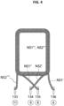
- FIG. 4 illustrates a structure in which a first secondary coil and a second secondary coil are electrically connected to respective terminal pins.
- FIG. 5 illustrates terminal pins of a final product of the magnetic component shown in FIG. 1 .
- FIG. 6 illustrates a front view of terminal pins of a final product of the magnetic component shown in FIG. 5 .
- the magnetic component of the embodiment is a multi-transformer, but the disclosure is not limited thereto.
- the transformer of the embodiment includes a bobbin unit 100, a coil unit (Not shown) wound around the bobbin unit 100, and cores 210 and 220.
- the coil unit(Not shown) includes two primary coils NP1 and NP2 and four secondary coils NS1, NS2, NS3, and NS4.
- the cores 210 and 220 are EE cores 210 and 220, and include an upper core 210 and a lower core 220, which have the same shape and structure.
- the upper core 210 includes a rectangular-shaped flat plate, a pair of outer legs 211 and 212 protruding from the left and right sides of the flat plate, and an intermediate leg 213 disposed between the outer legs 211 and 212.
- the lower core 220 includes a rectangular-shaped flat plate, a pair of outer legs 221 and 222 protruding from the flat plate, and an intermediate leg 223.
- a portion of the bobbin unit 100 is interposed between the upper core 210 and the lower core 220, and is assembled to the upper core 210 and the lower core 220 so as to be disposed inside the cores 210 and 220.
- the bobbin unit 100 has a through-hole 140 formed therein.
- the bobbin unit 100 includes a wound portion 110, around which the coils are wound, and a pair of flange portions 120 and 130, which are disposed on both sides of the wound portion 110 in an X-axis direction. Based on FIG. 2 , an upper flange portion 120 is located above the wound portion 110, and a lower flange portion 130 is located below the wound portion 110.
- the upper flange portion 120 includes a middle portion 121, which is connected to the wound portion 110, and a first terminal accommodation portion 122, which is formed on one side of the middle portion 121 in a direction perpendicular to the X-axis direction (a Y-axis direction).
- the first terminal accommodation portion 122 is thicker than the middle portion 121, and protrudes further outwards than the middle portion 121 in the X-axis direction.
- the lower flange portion 130 has the same structure as the upper flange portion 120. That is, the lower flange portion 130 includes a middle portion 131 and a second terminal accommodation portion 132 formed on one side of the middle portion 131. As illustrated, the first terminal accommodation portion 122 and the second terminal accommodation portion 132 are spaced apart from each other in the X-axis direction. First terminal pins 123 to 126 are accommodated in the first terminal accommodation portion 122, and second terminal pins 133 to 136 are accommodated in the second terminal accommodation portion 132.
- the intermediate legs 213 and 223 of the cores 210 and 220 are inserted into the through-hole 140 formed in the bobbin unit 100.
- the middle portions 121 and 131 of the flange portions 120 and 130 of the bobbin unit 100 are disposed between the pair of outer legs 211 and 212 of the upper core 210 and between the pair of outer legs 221 and 222 of the lower core 220. In this way, the cores 210 and 220 and the bobbin unit 100 are assembled to each other.
- the coils wound around the wound portion 110 of the bobbin unit 100 are disposed so as to be aligned with the intermediate legs 213 and 223 of the cores 210 and 220.
- the primary coils NP1 and NP2 and the secondary coils NS1, NS2, NS3, and NS4 are wound around the wound portion 110 of the bobbin unit 100 in the Y-axis direction, which is perpendicular to the X-axis direction, about the X-axis.
- End portions of the secondary coils NS1, NS2, NS3, and NS4 are connected to the first and second terminal pins 123 to 126 and 133 to 136, which are formed on the front surface of the bobbin unit 100 in the Y-axis direction, and end portions of the primary coils extend from the wound portion and are connected to respective terminal pins, which are formed on the rear surface of the bobbin unit 100.
- the first and second terminal pins 123 to 126 and 133 to 136 for the secondary coils are mounted in multiple layers in the bobbin unit 100. Specifically, four first terminal pins 123 to 126 are mounted in the first terminal accommodation portion 122 of the upper flange portion 120, and four second terminal pins 133 to 136 are mounted in the second terminal accommodation portion 132 of the lower flange portion 130.
- the terminal pins 123 to 126 and 133 to 136 are disposed so as not to overlap each other when viewed in the X-axis direction. That is, none of the first terminal pins 123 to 126 of the upper flange portion 120 or the second terminal pins 133 to 136 of the lower flange portion 130 overlap each other in the X-axis direction.
- the terminal accommodation portion 122 of the upper flange portion 120 includes a pair of upper and lower surfaces 122b and 122c, which are oriented in the X-axis direction, and a side surface 122a, which interconnects the upper and lower surfaces 122b and 122c
- the terminal accommodation portion 132 of the lower flange portion 130 includes a pair of upper and lower surfaces 132b and 132c, which are oriented in the X-axis direction, and a side surface 132a, which interconnects the upper and lower surfaces 132b and 132c.
- the terminal pins 123 to 126 and 133 to 136 are mounted on the side surfaces 122a and 132a of the terminal accommodation portions 122 and 132.
- the terminal pins 123 to 126 and 133 to 136 may be integrally formed with the bobbin unit 100 through insert injection molding, or a separate insulative reinforcement portion may be formed at the bobbin unit 100 or around the coils.
- the terminal pins 123 to 126 and 133 to 136 may be mounted so as to be exposed to the outside.
- the insulative reinforcement portion may be made of a polymer-resin-based material, for example, epoxy resin, silicon resin, or the like. However, any of various materials may be used for the insulative reinforcement portion, so long as the same is capable of securing sufficient strength to realize as slim a final product as possible.
- the terminal pins 123 to 126 and 133 to 136 are mounted to the bobbin unit in the Y-axis direction, which is perpendicular to the X-axis direction, and then are bent in the X-axis direction, thereby forming the transformer as a final product, as shown in FIG. 5 .
- the terminal pins 123 to 126 and 133 to 136 are bent such that end portions thereof are located at the same mounting height h in the X-axis direction.
- the end portions of the terminal pins 123 to 126 and 133 to 136 may be located on a printed circuit board, and may be mounted thereon through soldering or the like.
- the mounting height h is the height at which the end portions of the terminal pins are located so as to be soldered on the printed circuit board.
- the terminal pins 123 to 126 and 133 to 136 are bent and extend in the X-axis direction beyond the lowermost surface of the transformer by the mounting height h. That is, the mounting height h is the height of each of the end portions, which does not overlap the transformer in the X-axis direction. In this case, among the end portions of the terminal pins, the end portion having the lowest height may be 85% to 99% of the height of the end portion having the highest height.
- connection of the first terminal pins 123 to 126, which are accommodated in the first terminal accommodation portion 122 located in the upper layer, and the second terminal pins 133 to 136, which are accommodated in the second terminal accommodation portion 132 located in the lower layer, to the secondary coils NS1, NS2, NS3, and NS4 will be described with reference to FIGs. 2 and 3 .
- correspondence between the reference numerals of the terminal pins of FIG. 2 and the reference numerals of the pins of FIG. 3 is defined as follows.
- the primary coils NP1 and NP2 include a first primary coil NP1 and a second primary coil NP2.
- the terminal pins for the primary coils are located on the rear surface of the bobbin unit 100, and thus are not visible in FIG. 2 .
- the secondary coils may form a plurality of turns NS1, NS2, NS3, and NS4.
- the turns may include a first secondary coil NS1, a second secondary coil NS2, a third secondary coil NS3, and a fourth secondary coil NS4.
- the terminal pins 123 to 126 and 133 to 136 connected to the turns of the secondary coils may be disposed in the two terminal accommodation portions 122 and 132, as shown in FIG. 2 .
- the first secondary coil NS1 and the second secondary coil NS2 correspond to the first primary coil NP1
- the third secondary coil NS3 and the fourth secondary coil NS4 correspond to the second primary coil NP2.
- the first secondary coil NS1 and the second secondary coil NS2 form a pair so as to correspond to the first primary coil NP1, and are logically and electrically connected to each other.
- the third secondary coil NS3 and the fourth secondary coil NS4 form a pair so as to correspond to the second primary coil NP2, and are logically and electrically connected to each other.
- the logical and electrical connection may be achieved through electrical connection via a circuit pattern formed on the printed circuit board.
- the first secondary coil NS1 and the second secondary coil NS2 are logically connected to each other, and thus are electrically connected to each other at the end portions thereof.
- each of the coils includes a winding portion, which is wound around the wound portion 110 of the bobbin unit 100, and a pair of a start-side extension portion and a finish-side extension portion, which extend from the winding portion to the terminal pin.
- the start-side extension portion of one of the secondary coils and the finish-side extension portion of the other of the secondary coils are electrically connected to each other.
- the embodiment will be described on the basis of the first secondary coil NS1 and the second secondary coil NS2 with reference to FIG. 4 .
- the finish-side extension portion NS1" of the first secondary coil NS1 and the start-side extension portion NS2' of the second secondary coil NS2 need to be electrically connected to each other, and thus the terminal pins 134 and 135 (pin 9 and pin 8) corresponding thereto may intersect each other, or may be disposed in the same layer.
- the finish-side extension portion of the third secondary coil NS3 and the start-side extension portion of the fourth secondary coil NS4 are electrically connected to each other. Therefore, the terminal pin 124 (pin 10) corresponding to the finish-side extension portion of the third secondary coil NS3 and the terminal pin 125 (pin 7) corresponding to the start-side extension portion of the fourth secondary coil NS4 need to be electrically connected to each other, and thus may intersect each other, or may be disposed in the same layer. However, in the embodiment, the finish-side extension portion of the third secondary coil NS3 and the start-side extension portion of the fourth secondary coil NS4 do not intersect each other due to the winding structure.
- the terminal pins 133 to 136 for the first and second secondary coils NS1 and NS2 are located in the second terminal accommodation portion 132, and the terminal pins 123 to 126 for the third and fourth secondary coils NS3 and NS4 are located in the first terminal accommodation portion 122.
- the terminal pins 123 to 126 and 133 to 136 corresponding thereto are disposed in different layers, thereby minimizing or preventing the risk of electrical connection between the extension portions of the coils.
- an end portion having a lowest height is 85% to 99% of a height of an end portion having a highest height.
- extension portions of a plurality of coils are capable of being disposed in a confined space without the risk of interference or a short therebetween. This is consequently very advantageous from the aspect of slimness of a magnetic component.
- manufacturing costs and manufacturing time may be reduced, quality uniformity may be improved, and a slim magnetic component may be obtained.
Landscapes
- Engineering & Computer Science (AREA)
- Power Engineering (AREA)
- Microelectronics & Electronic Packaging (AREA)
- Coils Of Transformers For General Uses (AREA)
- Coils Or Transformers For Communication (AREA)
- Insulating Of Coils (AREA)
Abstract
Description
- Embodiments relate to a slim-type magnetic component.
- Magnetic components are used for power supply devices of electronic apparatuses, such as TVs, and meanwhile, the demand for slim electronic apparatuses, such as TVs, is accelerating.
- Because electronic apparatuses are produced in slim form factors, there is a large demand for slim-type magnetic components. Particularly, technical competition to produce a slim-type magnetic component having a size of 15 mm or less has intensified.
- As one example of magnetic components, a transformer is generally configured such that terminal pins are mounted to both sides of a bobbin unit, primary coils are connected to the terminal pins mounted to one side of the bobbin unit, and secondary coils are connected to the terminal pins mounted to the opposite side of the bobbin unit.
- As one example of transformers, there is a multi-transformer (a multi-winding transformer), which is a multi-output transformer configured to convert power input thereto so as to simultaneously output various magnitudes of voltage/current. However, the multi-transformer has a problem in that interference or a short between secondary coils occurs easily due to the reduced size thereof.
- Particularly, in the conventional art, terminal pins, to which secondary coils are connected, are arranged in a single layer, and an end portion of each of the coils is withdrawn out of a coil-winding portion and is electrically connected to a corresponding one of the terminal pins through soldering or the like. In this case, when end portions of the secondary coils, between which a short should not occur, are connected to respective terminal pins while intersecting each other, the end portions of the secondary coils may interfere with each other, and a short may occur therebetween through portions covered by damaged sheaths during a soldering process.
- In order to solve the above problems with the coils, there may be considered a structure in which a protrusion is formed above a terminal pin so as to be spaced a predetermined distance apart from the terminal pin and in which a coil extension portion extending from a coil-winding portion to the terminal pin is wound around the protrusion, thereby preventing interference or a short between coil extension portions. In this case, however, it is not possible to use automatic winding equipment when winding the end portion of the coil around the protrusion. Therefore, process lead time and production costs increase. In addition, quality uniformity is deteriorated, and production yield decreases. In addition, loss of materials increases, and thus material costs increase.
- Embodiments provide a slim-type magnetic component capable of solving at least one of the above-mentioned problems.
- Embodiments provide a slim-type magnetic component capable of preventing interference or a short between a plurality of coils when the coils are connected to respective terminal pins, minimizing the size thereof, and enabling automated winding using automatic winding equipment.
- In one embodiment, a magnetic component includes a core unit including an upper core and a lower core, a bobbin unit having at least a portion disposed inside the core unit, and a coil unit including primary coils and secondary coils wound around the bobbin unit in a second direction, which is perpendicular to a first direction oriented from the upper core toward the lower core. The bobbin unit includes a first terminal accommodation portion and a second terminal accommodation portion formed in one side thereof to accommodate terminal pin portions including first terminal pins and second terminal pins. The first terminal accommodation portion accommodates the first terminal pins, connected to at least some of the secondary coils in the second direction and having end portions bent in the first direction. The second terminal accommodation portion accommodates the second terminal pins, connected to the remaining ones of the secondary coils in the second direction and having end portions bent in the first direction. The first terminal accommodation portion and the second terminal accommodation portion are spaced apart from each other in the first direction.
- In at least one embodiment of the present disclosure, the first terminal pins and the second terminal pins may be disposed so as not to overlap each other in the first direction.
- In at least one embodiment of the present disclosure, the secondary coils may include a first turn and a second turn. Each of the first turn and the second turn may include a winding portion wound around the bobbin unit and two extension portions extending from the winding portion toward the terminal pin portions. One of the extension portions of the first turn and one of the extension portions of the second turn may be electrically connected to each other. The extension portion of the first turn and the extension portion of the second turn, which are electrically connected to each other, may be disposed in the first terminal accommodation portion.
- In at least one embodiment of the present disclosure, the remaining one of the extension portions of the first turn and the remaining one of the extension portions of the second turn may be electrically separated from each other. The extension portion of the first turn and the extension portion of the second turn, which are electrically separated from each other, may be respectively disposed in the first terminal accommodation portion and the second terminal accommodation portion.
- In at least one embodiment of the present disclosure, the primary coils may be connected to terminal pins formed on the other side opposite the one side of the bobbin unit.
- In at least one embodiment of the present disclosure, the first terminal accommodation portion and the second terminal accommodation portion may be disposed parallel to each other in the first direction.
- In at least one embodiment of the present disclosure, among the end portions of the first terminal pins and the end portions of the second terminal pins, which are bent in the first direction, the end portion having the lowest height may be 85% to 99% of the height of the end portion having the highest height.
- In at least one embodiment of the present disclosure, the magnetic component may further include an insulative reinforcement portion disposed at the bobbin unit or around the coil unit.
- Here, the insulative reinforcement portion may include at least one of epoxy resin or silicon resin.
- In at least one embodiment of the present disclosure, the bobbin unit may have a through-hole formed in the center thereof. The core unit may include at least one intermediate leg passing through the through-hole and at least one pair of outer legs disposed at both sides of the bobbin unit.
- Arrangements and embodiments may be described in detail with reference to the following drawings in which like reference numerals refer to like elements and wherein:
-
FIG. 1 is an exploded perspective view of a magnetic component according to an embodiment of the present disclosure; -
FIG. 2 illustrates the bobbin unit and the coil assembly shown inFIG. 1 ; -
FIG. 3 illustrates a pin map of the magnetic component shown inFIG. 1 ; -
FIG. 4 illustrates a structure in which a pair of secondary coils is connected to respective terminal pins; and -
FIG. 5 illustrates terminal pins of a final product of the magnetic component shown inFIG. 1 . -
FIG. 6 illustrates a front view of terminal pins of a final product of the magnetic component shown inFIG. 5 . - The present disclosure will now be described more fully hereinafter with reference to the accompanying drawings, in which various embodiments are shown. The examples, however, may be embodied in many different forms and should not be construed as being limited to the embodiments set forth herein. It is to be understood that the present disclosure covers all modifications, equivalents, and alternatives falling within the scope and spirit of the present disclosure.
- The terms "module" and "unit", with which the names of components are suffixed, are assigned or used only in consideration of preparation of the specification, and may be interchanged with each other. The terms do not have any distinguishable meanings or roles.
- While ordinal numbers including "first", "second", etc. may be used to describe various components, they are not intended to limit the components. These expressions are used only to distinguish one component from another component.
- As used herein, the term "and/or" includes any and all combinations of one or more of the associated listed items. For example, the phrase "A and/or B" means "(A), (B), or (A and B)".
- It will be understood that when an element is referred to as being "connected" or "coupled" to another element, it can be directly connected or coupled to the other element, or intervening elements may be present.
- In the description of the embodiments, it will be understood that when an element, such as a layer (film), a region, a pattern or a structure, is referred to as being "on" or "under" another element, such as a substrate, a layer (film), a region, a pad or a pattern, the term "on" or "under" means that the element is "directly" on or under another element or is "indirectly" formed such that an intervening element may also be present. In addition, it will also be understood that criteria of on or under is on the basis of the drawing. For example, the phrase "B on" merely indicates that B is illustrated in the drawing as being located on A, unless otherwise defined or unless A must be located on B due to the characteristics of A or B. In an actual product, B may be located under A, or B and A may be disposed in a leftward-rightward direction.
- The thickness or size of a layer (film), a region, a pattern, or a structure shown in the drawings may be exaggerated, omitted or schematically drawn for the convenience and clarity of explanation, and may not accurately reflect the actual size.
- The terminology used herein is for the purpose of describing particular embodiments only and is not intended to be limiting of exemplary embodiments of the disclosure. As used herein, the singular forms "a", "an", and "the", are intended to include the plural forms as well, unless the context clearly indicates otherwise. It will be further understood that the terms "comprises", "comprising", "includes", and/or "including", when used herein, specify the presence of stated features, integers, steps, operations, elements, components, or combinations thereof, but do not preclude the presence or addition of one or more other features, integers, steps, operations, elements, components, or combinations thereof.
- Unless otherwise defined, all terms used herein, which include technical or scientific terms, have the same meanings as those generally appreciated by those skilled in the art. The terms, such as ones defined in common dictionaries, should be interpreted as having the same meanings as terms in the context of pertinent technology, and should not be interpreted as having ideal or excessively formal meanings unless clearly defined in the specification.
- Hereinafter, an embodiment of the present disclosure will be described in detail with reference to
FIGs. 1 to 6 . -
FIG. 1 is an exploded perspective view of a magnetic component according to an embodiment of the present disclosure.FIG. 2 illustrates the bobbin unit and the coil assembly shown inFIG. 1 .FIG. 3 illustrates a pin map of the magnetic component shown inFIG. 1 .FIG. 4 illustrates a structure in which a first secondary coil and a second secondary coil are electrically connected to respective terminal pins.FIG. 5 illustrates terminal pins of a final product of the magnetic component shown inFIG. 1 .FIG. 6 illustrates a front view of terminal pins of a final product of the magnetic component shown inFIG. 5 . - The magnetic component of the embodiment is a multi-transformer, but the disclosure is not limited thereto.
- The transformer of the embodiment includes a
bobbin unit 100, a coil unit (Not shown) wound around thebobbin unit 100, andcores - The
cores EE cores upper core 210 and alower core 220, which have the same shape and structure. - The
upper core 210 includes a rectangular-shaped flat plate, a pair ofouter legs intermediate leg 213 disposed between theouter legs - Similarly, the
lower core 220 includes a rectangular-shaped flat plate, a pair ofouter legs intermediate leg 223. - A portion of the
bobbin unit 100 is interposed between theupper core 210 and thelower core 220, and is assembled to theupper core 210 and thelower core 220 so as to be disposed inside thecores - The
bobbin unit 100 has a through-hole 140 formed therein. Thebobbin unit 100 includes awound portion 110, around which the coils are wound, and a pair offlange portions wound portion 110 in an X-axis direction. Based onFIG. 2 , anupper flange portion 120 is located above thewound portion 110, and alower flange portion 130 is located below thewound portion 110. - The
upper flange portion 120 includes amiddle portion 121, which is connected to thewound portion 110, and a firstterminal accommodation portion 122, which is formed on one side of themiddle portion 121 in a direction perpendicular to the X-axis direction (a Y-axis direction). The firstterminal accommodation portion 122 is thicker than themiddle portion 121, and protrudes further outwards than themiddle portion 121 in the X-axis direction. - The
lower flange portion 130 has the same structure as theupper flange portion 120. That is, thelower flange portion 130 includes amiddle portion 131 and a secondterminal accommodation portion 132 formed on one side of themiddle portion 131. As illustrated, the firstterminal accommodation portion 122 and the secondterminal accommodation portion 132 are spaced apart from each other in the X-axis direction. Firstterminal pins 123 to 126 are accommodated in the firstterminal accommodation portion 122, and second terminal pins 133 to 136 are accommodated in the secondterminal accommodation portion 132. - The
intermediate legs cores hole 140 formed in thebobbin unit 100. Themiddle portions flange portions bobbin unit 100 are disposed between the pair ofouter legs upper core 210 and between the pair ofouter legs lower core 220. In this way, thecores bobbin unit 100 are assembled to each other. - After assembly, the coils wound around the
wound portion 110 of thebobbin unit 100 are disposed so as to be aligned with theintermediate legs cores - Although not illustrated in
FIG. 2 , the primary coils NP1 and NP2 and the secondary coils NS1, NS2, NS3, and NS4 are wound around thewound portion 110 of thebobbin unit 100 in the Y-axis direction, which is perpendicular to the X-axis direction, about the X-axis. End portions of the secondary coils NS1, NS2, NS3, and NS4 are connected to the first and second terminal pins 123 to 126 and 133 to 136, which are formed on the front surface of thebobbin unit 100 in the Y-axis direction, and end portions of the primary coils extend from the wound portion and are connected to respective terminal pins, which are formed on the rear surface of thebobbin unit 100. - As illustrated in
FIG. 2 , the first and second terminal pins 123 to 126 and 133 to 136 for the secondary coils are mounted in multiple layers in thebobbin unit 100. Specifically, four first terminal pins 123 to 126 are mounted in the firstterminal accommodation portion 122 of theupper flange portion 120, and four second terminal pins 133 to 136 are mounted in the secondterminal accommodation portion 132 of thelower flange portion 130. - Based on
FIG. 2 , the terminal pins 123 to 126 and 133 to 136 are disposed so as not to overlap each other when viewed in the X-axis direction. That is, none of the first terminal pins 123 to 126 of theupper flange portion 120 or the second terminal pins 133 to 136 of thelower flange portion 130 overlap each other in the X-axis direction. - The
terminal accommodation portion 122 of theupper flange portion 120 includes a pair of upper andlower surfaces side surface 122a, which interconnects the upper andlower surfaces terminal accommodation portion 132 of thelower flange portion 130 includes a pair of upper andlower surfaces side surface 132a, which interconnects the upper andlower surfaces side surfaces terminal accommodation portions bobbin unit 100 through insert injection molding, or a separate insulative reinforcement portion may be formed at thebobbin unit 100 or around the coils. The terminal pins 123 to 126 and 133 to 136 may be mounted so as to be exposed to the outside. The insulative reinforcement portion may be made of a polymer-resin-based material, for example, epoxy resin, silicon resin, or the like. However, any of various materials may be used for the insulative reinforcement portion, so long as the same is capable of securing sufficient strength to realize as slim a final product as possible. - The terminal pins 123 to 126 and 133 to 136 are mounted to the bobbin unit in the Y-axis direction, which is perpendicular to the X-axis direction, and then are bent in the X-axis direction, thereby forming the transformer as a final product, as shown in
FIG. 5 . In detail, as shown inFIG. 5 , the terminal pins 123 to 126 and 133 to 136 are bent such that end portions thereof are located at the same mounting height h in the X-axis direction. The end portions of theterminal pins 123 to 126 and 133 to 136 may be located on a printed circuit board, and may be mounted thereon through soldering or the like. Here, the mounting height h is the height at which the end portions of the terminal pins are located so as to be soldered on the printed circuit board. The terminal pins 123 to 126 and 133 to 136 are bent and extend in the X-axis direction beyond the lowermost surface of the transformer by the mounting height h. That is, the mounting height h is the height of each of the end portions, which does not overlap the transformer in the X-axis direction. In this case, among the end portions of the terminal pins, the end portion having the lowest height may be 85% to 99% of the height of the end portion having the highest height. - Hereinafter, connection of the first terminal pins 123 to 126, which are accommodated in the first
terminal accommodation portion 122 located in the upper layer, and the second terminal pins 133 to 136, which are accommodated in the secondterminal accommodation portion 132 located in the lower layer, to the secondary coils NS1, NS2, NS3, and NS4 will be described with reference toFIGs. 2 and3 . For better understanding, correspondence between the reference numerals of the terminal pins ofFIG. 2 and the reference numerals of the pins ofFIG. 3 is defined as follows. - 123 : ○,12 124 : ○,10 125 : ○,7 126 : ○,5
- 133 : ○,11 134 : ○,9 135 : ○,8 136 : ○,6
- The primary coils NP1 and NP2 include a first primary coil NP1 and a second primary coil NP2. The terminal pins for the primary coils are located on the rear surface of the
bobbin unit 100, and thus are not visible inFIG. 2 . - According to the embodiment, the secondary coils may form a plurality of turns NS1, NS2, NS3, and NS4. The turns may include a first secondary coil NS1, a second secondary coil NS2, a third secondary coil NS3, and a fourth secondary coil NS4. The terminal pins 123 to 126 and 133 to 136 connected to the turns of the secondary coils may be disposed in the two
terminal accommodation portions FIG. 2 . The first secondary coil NS1 and the second secondary coil NS2 correspond to the first primary coil NP1, and the third secondary coil NS3 and the fourth secondary coil NS4 correspond to the second primary coil NP2. - The first secondary coil NS1 and the second secondary coil NS2 form a pair so as to correspond to the first primary coil NP1, and are logically and electrically connected to each other.
- The third secondary coil NS3 and the fourth secondary coil NS4 form a pair so as to correspond to the second primary coil NP2, and are logically and electrically connected to each other.
- Here, the logical and electrical connection may be achieved through electrical connection via a circuit pattern formed on the printed circuit board.
- The first secondary coil NS1 and the second secondary coil NS2 are logically connected to each other, and thus are electrically connected to each other at the end portions thereof.
- For example, each of the coils includes a winding portion, which is wound around the
wound portion 110 of thebobbin unit 100, and a pair of a start-side extension portion and a finish-side extension portion, which extend from the winding portion to the terminal pin. Among a pair of secondary coils that are logically and electrically connected to each other, the start-side extension portion of one of the secondary coils and the finish-side extension portion of the other of the secondary coils are electrically connected to each other. - The embodiment will be described on the basis of the first secondary coil NS1 and the second secondary coil NS2 with reference to
FIG. 4 . Referring toFIG. 4 , the finish-side extension portion NS1" of the first secondary coil NS1 and the start-side extension portion NS2' of the second secondary coil NS2 need to be electrically connected to each other, and thus the terminal pins 134 and 135 (pin 9 and pin 8) corresponding thereto may intersect each other, or may be disposed in the same layer. - Although not illustrated, because the third secondary coil NS3 and the fourth secondary coil NS4, which correspond to the second primary coil NP2, are also logically and electrically connected to each other, the finish-side extension portion of the third secondary coil NS3 and the start-side extension portion of the fourth secondary coil NS4 are electrically connected to each other. Therefore, the terminal pin 124 (pin 10) corresponding to the finish-side extension portion of the third secondary coil NS3 and the terminal pin 125 (pin 7) corresponding to the start-side extension portion of the fourth secondary coil NS4 need to be electrically connected to each other, and thus may intersect each other, or may be disposed in the same layer. However, in the embodiment, the finish-side extension portion of the third secondary coil NS3 and the start-side extension portion of the fourth secondary coil NS4 do not intersect each other due to the winding structure.
- In the embodiment, as shown in
FIG. 2 , the terminal pins 133 to 136 for the first and second secondary coils NS1 and NS2 are located in the secondterminal accommodation portion 132, and theterminal pins 123 to 126 for the third and fourth secondary coils NS3 and NS4 are located in the firstterminal accommodation portion 122. - In the case in which the extension portions of the coils that should not be electrically connected to each other intersect each other when viewed in the X-axis direction, the terminal pins 123 to 126 and 133 to 136 corresponding thereto are disposed in different layers, thereby minimizing or preventing the risk of electrical connection between the extension portions of the coils.
- Based on
FIG. 6 , among the end portions of the first terminal pins, bent in the first direction so as not to overlap the bobbin unit in the second direction, and the end portions of the second terminal pins, bent in the first direction so as not to overlap the bobbin unit in the second direction, an end portion having a lowest height is 85% to 99% of a height of an end portion having a highest height. - According to the above-described multi-layer arrangement structure of the terminal pins, extension portions of a plurality of coils are capable of being disposed in a confined space without the risk of interference or a short therebetween. This is consequently very advantageous from the aspect of slimness of a magnetic component.
- As is apparent from the above description, according to the present disclosure, manufacturing costs and manufacturing time may be reduced, quality uniformity may be improved, and a slim magnetic component may be obtained.
- It will be apparent to those skilled in the art that various changes in form and details may be made without departing from the spirit and essential characteristics of the disclosure set forth herein. Accordingly, the above detailed description is not intended to be construed to limit the disclosure in all aspects and to be considered by way of example. The scope of the disclosure should be determined by reasonable interpretation of the appended claims and all equivalent modifications made without departing from the disclosure should be included in the following claims.
Claims (15)
- A magnetic component comprising:a core unit comprising an upper core and a lower core;a bobbin unit having at least a portion disposed inside the core unit; anda coil unit comprising primary coils and secondary coils wound around the bobbin unit in a second direction, the second direction being perpendicular to a first direction oriented from the upper core toward the lower core,wherein the secondary coils comprise a plurality of first terminal pins and a plurality of second terminal pins,wherein the bobbin unit comprises a first terminal accommodation portion and a second terminal accommodation portion formed in one side thereof,wherein the plurality of first terminal pins extend from the first terminal accommodation portion in the second direction and are bent in the first direction,wherein the plurality of second terminal pins extend from the second terminal accommodation portion in the second direction and are bent in the first direction; andwherein the first terminal accommodation portion and the second terminal accommodation portion are spaced apart from each other in the first direction.
- The magnetic component according to claim 1, wherein the first terminal pins and the second terminal pins are disposed so as not to overlap each other in the first direction.
- The magnetic component according to claim 1, wherein the secondary coils comprise a first turn and a second turn,wherein each of the first turn and the second turn comprises a winding portion wound around the bobbin unit and two extension portions extending from the winding portion toward the terminal pin portions,wherein one of the extension portions of the first turn and one of the extension portions of the second turn are electrically connected to each other, andwherein the one of the extension portions of the first turn and the one of the extension portions of the second turn, electrically connected to each other, are disposed in the first terminal accommodation portion.
- The magnetic component according to claim 3, wherein a remaining one of the extension portions of the first turn and a remaining one of the extension portions of the second turn are electrically separated from each other, and
wherein the remaining one of the extension portions of the first turn and the remaining one of the extension portions of the second turn, electrically separated from each other, are respectively disposed in the first terminal accommodation portion and the second terminal accommodation portion. - (Currently amended) The magnetic component according to claim 4, wherein the primary coils are connected to terminal pins formed on another side opposite the one side of the bobbin unit.
- The magnetic component according to claim 5, wherein the primary coils comprise a first primary coil and a second primary coil, and
wherein the secondary coils comprise:a first secondary coil corresponding to the first primary coil;a second secondary coil electrically connected to the first secondary coil;a third secondary coil corresponding to the second primary coil; anda fourth secondary coil electrically connected to the third secondary coil. - The magnetic component according to claim 6, wherein the first secondary coil is electrically connected at a finish-side extension portion thereof to a start-side extension portion of the second secondary coil, and
wherein the third secondary coil is electrically connected at a finish-side extension portion thereof to a start-side extension portion of the fourth secondary coil. - The magnetic component according to claim 6, wherein terminal pins for the first secondary coil and the second secondary coil are disposed in the second terminal accommodation portion, and
wherein terminal pins for the third secondary coil and the fourth secondary coil are disposed in the first terminal accommodation portion. - The magnetic component according to claim 1, wherein the first terminal accommodation portion and the second terminal accommodation portion are disposed parallel to each other in the first direction.
- The magnetic component according to claim 1, wherein, among the end portions of the first terminal pins, bent in the first direction so as not to overlap the bobbin unit in the second direction, and the end portions of the second terminal pins, bent in the first direction so as not to overlap the bobbin unit in the second direction, an end portion having a lowest height is 85% to 99% of a height of an end portion having a highest height.
- The magnetic component according to claim 1, further comprising:
an insulative reinforcement portion disposed on the bobbin unit or around the coil unit. - The magnetic component according to claim 11, wherein the insulative reinforcement portion comprises at least one of epoxy resin or silicon resin.
- The magnetic component according to claim 1, wherein the bobbin unit has a through-hole formed in a center thereof, and
wherein the core unit comprises:at least one intermediate leg passing through the through-hole; andat least one pair of outer legs disposed on both sides of the bobbin unit. - The magnetic component according to claim 13, wherein the bobbin unit comprises:a wound portion around which the primary coils and the secondary coils are wound; anda pair of flange portions disposed on both sides of the wound portion in the first direction.
- The magnetic component according to claim 14, wherein the pair of flange portions comprises:an upper flange portion having the first terminal accommodation portion in one side thereof; anda lower flange portion spaced apart from the upper flange portion in the first direction and having the second terminal accommodation portion in one side thereof.
Applications Claiming Priority (1)
| Application Number | Priority Date | Filing Date | Title |
|---|---|---|---|
| KR1020210128182A KR102526063B1 (en) | 2021-09-28 | 2021-09-28 | Slim-sized Magnetic Component |
Publications (2)
| Publication Number | Publication Date |
|---|---|
| EP4156211A1 true EP4156211A1 (en) | 2023-03-29 |
| EP4156211B1 EP4156211B1 (en) | 2026-02-18 |
Family
ID=83505872
Family Applications (1)
| Application Number | Title | Priority Date | Filing Date |
|---|---|---|---|
| EP22198349.7A Active EP4156211B1 (en) | 2021-09-28 | 2022-09-28 | Slim-type magnetic component |
Country Status (5)
| Country | Link |
|---|---|
| US (1) | US12334248B2 (en) |
| EP (1) | EP4156211B1 (en) |
| JP (1) | JP2023049046A (en) |
| KR (4) | KR102526063B1 (en) |
| CN (2) | CN115881406A (en) |
Families Citing this family (3)
| Publication number | Priority date | Publication date | Assignee | Title |
|---|---|---|---|---|
| CN116666079A (en) * | 2023-06-27 | 2023-08-29 | 迈世腾科技(山东)有限公司 | Transformer |
| CN116646155A (en) * | 2023-06-27 | 2023-08-25 | 迈世腾科技(山东)有限公司 | A new type of transformer |
| KR20250148216A (en) * | 2024-04-05 | 2025-10-14 | 엘지이노텍 주식회사 | Wireless power transmit receive module |
Citations (4)
| Publication number | Priority date | Publication date | Assignee | Title |
|---|---|---|---|---|
| US20110043315A1 (en) * | 2009-08-24 | 2011-02-24 | Tdk Corporation | Transformer |
| US20170032888A1 (en) * | 2015-07-31 | 2017-02-02 | Solum Co., Ltd. | Transformer and plate coil molded body |
| JP2017212355A (en) * | 2016-05-26 | 2017-11-30 | Tdk株式会社 | Coil device |
| GB2568497A (en) * | 2017-11-17 | 2019-05-22 | Invertek Drives Ltd | A transformer and a method of manufacturing a transformer |
Family Cites Families (12)
| Publication number | Priority date | Publication date | Assignee | Title |
|---|---|---|---|---|
| JPH0519938Y2 (en) * | 1987-12-08 | 1993-05-25 | ||
| JPH0731527Y2 (en) * | 1990-07-16 | 1995-07-19 | 株式会社村田製作所 | Trance |
| KR19980027843U (en) | 1996-11-19 | 1998-08-05 | 배순훈 | Transformer with Multi Pin Structure |
| KR200273958Y1 (en) | 1998-12-30 | 2002-09-17 | 한국델파이주식회사 | integral type intermediate steering shaft structure |
| KR200203634Y1 (en) | 2000-06-21 | 2000-11-15 | 동남전자주식회사 | Fabricated structure of temperature fuse for transformer bobbin |
| US20120038448A1 (en) * | 2010-08-11 | 2012-02-16 | Samsung Electro-Mechanics Co., Ltd. | Transformer and display device using the same |
| JP5799687B2 (en) * | 2011-09-07 | 2015-10-28 | Fdk株式会社 | Trance |
| KR101686975B1 (en) * | 2015-10-08 | 2017-01-20 | 티디케이한국 주식회사 | Coil device |
| JP6234538B1 (en) | 2016-11-04 | 2017-11-22 | 三菱電機株式会社 | Electromagnetic parts |
| KR101858117B1 (en) | 2016-12-19 | 2018-05-15 | 이주열 | Dual Spiral Transformer |
| KR102023252B1 (en) * | 2017-02-10 | 2019-09-19 | 티디케이한국 주식회사 | Bobin assembly, transformer comprising same, and winding method |
| JP7157383B2 (en) * | 2018-12-28 | 2022-10-20 | Tdk株式会社 | Coil device |
-
2021
- 2021-09-28 KR KR1020210128182A patent/KR102526063B1/en active Active
-
2022
- 2022-09-28 EP EP22198349.7A patent/EP4156211B1/en active Active
- 2022-09-28 CN CN202211193776.0A patent/CN115881406A/en active Pending
- 2022-09-28 CN CN202410540265.4A patent/CN118398351A/en active Pending
- 2022-09-28 JP JP2022155576A patent/JP2023049046A/en active Pending
- 2022-09-28 US US17/936,209 patent/US12334248B2/en active Active
-
2023
- 2023-03-13 KR KR1020230032364A patent/KR102657121B1/en active Active
-
2024
- 2024-02-26 KR KR1020240027470A patent/KR102828492B1/en active Active
-
2025
- 2025-06-27 KR KR1020250086025A patent/KR20250105593A/en active Pending
Patent Citations (4)
| Publication number | Priority date | Publication date | Assignee | Title |
|---|---|---|---|---|
| US20110043315A1 (en) * | 2009-08-24 | 2011-02-24 | Tdk Corporation | Transformer |
| US20170032888A1 (en) * | 2015-07-31 | 2017-02-02 | Solum Co., Ltd. | Transformer and plate coil molded body |
| JP2017212355A (en) * | 2016-05-26 | 2017-11-30 | Tdk株式会社 | Coil device |
| GB2568497A (en) * | 2017-11-17 | 2019-05-22 | Invertek Drives Ltd | A transformer and a method of manufacturing a transformer |
Also Published As
| Publication number | Publication date |
|---|---|
| JP2023049046A (en) | 2023-04-07 |
| CN118398351A (en) | 2024-07-26 |
| KR20230045388A (en) | 2023-04-04 |
| KR20230045593A (en) | 2023-04-04 |
| KR20240031289A (en) | 2024-03-07 |
| EP4156211B1 (en) | 2026-02-18 |
| CN115881406A (en) | 2023-03-31 |
| KR20250105593A (en) | 2025-07-08 |
| KR102828492B1 (en) | 2025-07-03 |
| US12334248B2 (en) | 2025-06-17 |
| KR102526063B1 (en) | 2023-04-26 |
| US20230101943A1 (en) | 2023-03-30 |
| KR102657121B1 (en) | 2024-04-15 |
Similar Documents
| Publication | Publication Date | Title |
|---|---|---|
| EP4156211B1 (en) | Slim-type magnetic component | |
| US8502633B2 (en) | Planar transformer and method of manufacturing the same | |
| KR100879251B1 (en) | Balance trance | |
| JP6572871B2 (en) | Transformer device and assembly method thereof | |
| US9396863B2 (en) | Transformer | |
| US8009007B2 (en) | Inductance part | |
| US12614661B2 (en) | Transformer and flat panel display device including same | |
| KR101124003B1 (en) | Transformer and flat panel display device using the same | |
| US20120154363A1 (en) | Line filter and flat panel display device using the same | |
| US8188825B2 (en) | Transformer structure | |
| US7948350B2 (en) | Coil component | |
| JPH07245217A (en) | Inductance element and coil for the element | |
| KR102541556B1 (en) | Transformer and display device including the same | |
| US12580120B2 (en) | Transformer and flat panel display device comprising same | |
| US20110102119A1 (en) | Resonant transformer | |
| KR102553809B1 (en) | Transformer and display device including the same | |
| KR101858117B1 (en) | Dual Spiral Transformer | |
| KR102695486B1 (en) | Magnetic component and circuit board including the same | |
| KR100809213B1 (en) | Integrated Transformer | |
| US20160027575A1 (en) | Circuit board magnetic component with integrated ground structure and methods for manufacture | |
| EP4600983A1 (en) | Transformer | |
| EP4621818A1 (en) | Transformer and display device including same | |
| JP2013182927A (en) | Coil component | |
| KR101489814B1 (en) | Coil component | |
| KR20250146172A (en) | Transformer |
Legal Events
| Date | Code | Title | Description |
|---|---|---|---|
| PUAI | Public reference made under article 153(3) epc to a published international application that has entered the european phase |
Free format text: ORIGINAL CODE: 0009012 |
|
| STAA | Information on the status of an ep patent application or granted ep patent |
Free format text: STATUS: THE APPLICATION HAS BEEN PUBLISHED |
|
| AK | Designated contracting states |
Kind code of ref document: A1 Designated state(s): AL AT BE BG CH CY CZ DE DK EE ES FI FR GB GR HR HU IE IS IT LI LT LU LV MC MK MT NL NO PL PT RO RS SE SI SK SM TR |
|
| STAA | Information on the status of an ep patent application or granted ep patent |
Free format text: STATUS: REQUEST FOR EXAMINATION WAS MADE |
|
| 17P | Request for examination filed |
Effective date: 20230927 |
|
| RBV | Designated contracting states (corrected) |
Designated state(s): AL AT BE BG CH CY CZ DE DK EE ES FI FR GB GR HR HU IE IS IT LI LT LU LV MC MK MT NL NO PL PT RO RS SE SI SK SM TR |
|
| STAA | Information on the status of an ep patent application or granted ep patent |
Free format text: STATUS: EXAMINATION IS IN PROGRESS |
|
| 17Q | First examination report despatched |
Effective date: 20250313 |
|
| GRAP | Despatch of communication of intention to grant a patent |
Free format text: ORIGINAL CODE: EPIDOSNIGR1 |
|
| STAA | Information on the status of an ep patent application or granted ep patent |
Free format text: STATUS: GRANT OF PATENT IS INTENDED |
|
| INTG | Intention to grant announced |
Effective date: 20251029 |
|
| RIN1 | Information on inventor provided before grant (corrected) |
Inventor name: KIM, BI YI Inventor name: KIM, YONG HWAN Inventor name: OH, SUE KYUNG |
|
| GRAS | Grant fee paid |
Free format text: ORIGINAL CODE: EPIDOSNIGR3 |
|
| GRAA | (expected) grant |
Free format text: ORIGINAL CODE: 0009210 |
|
| STAA | Information on the status of an ep patent application or granted ep patent |
Free format text: STATUS: THE PATENT HAS BEEN GRANTED |
|
| AK | Designated contracting states |
Kind code of ref document: B1 Designated state(s): AL AT BE BG CH CY CZ DE DK EE ES FI FR GB GR HR HU IE IS IT LI LT LU LV MC MK MT NL NO PL PT RO RS SE SI SK SM TR |
|
| REG | Reference to a national code |
Ref country code: CH Ref legal event code: F10 Free format text: ST27 STATUS EVENT CODE: U-0-0-F10-F00 (AS PROVIDED BY THE NATIONAL OFFICE) Effective date: 20260218 Ref country code: GB Ref legal event code: FG4D |
|
| REG | Reference to a national code |
Ref country code: IE Ref legal event code: FG4D |
|
| REG | Reference to a national code |
Ref country code: DE Ref legal event code: R096 Ref document number: 602022030497 Country of ref document: DE |
|
| REG | Reference to a national code |
Ref country code: NL Ref legal event code: MP Effective date: 20260218 |
|
| PG25 | Lapsed in a contracting state [announced via postgrant information from national office to epo] |
Ref country code: RS Free format text: LAPSE BECAUSE OF FAILURE TO SUBMIT A TRANSLATION OF THE DESCRIPTION OR TO PAY THE FEE WITHIN THE PRESCRIBED TIME-LIMIT Effective date: 20260518 |
|
| PG25 | Lapsed in a contracting state [announced via postgrant information from national office to epo] |
Ref country code: ES Free format text: LAPSE BECAUSE OF FAILURE TO SUBMIT A TRANSLATION OF THE DESCRIPTION OR TO PAY THE FEE WITHIN THE PRESCRIBED TIME-LIMIT Effective date: 20260218 |
|
| PG25 | Lapsed in a contracting state [announced via postgrant information from national office to epo] |
Ref country code: PL Free format text: LAPSE BECAUSE OF FAILURE TO SUBMIT A TRANSLATION OF THE DESCRIPTION OR TO PAY THE FEE WITHIN THE PRESCRIBED TIME-LIMIT Effective date: 20260218 |
|
| PG25 | Lapsed in a contracting state [announced via postgrant information from national office to epo] |
Ref country code: GR Free format text: LAPSE BECAUSE OF FAILURE TO SUBMIT A TRANSLATION OF THE DESCRIPTION OR TO PAY THE FEE WITHIN THE PRESCRIBED TIME-LIMIT Effective date: 20260519 |
|
| REG | Reference to a national code |
Ref country code: LT Ref legal event code: MG9D |
|
| PG25 | Lapsed in a contracting state [announced via postgrant information from national office to epo] |
Ref country code: LT Free format text: LAPSE BECAUSE OF FAILURE TO SUBMIT A TRANSLATION OF THE DESCRIPTION OR TO PAY THE FEE WITHIN THE PRESCRIBED TIME-LIMIT Effective date: 20260218 |
|
| PG25 | Lapsed in a contracting state [announced via postgrant information from national office to epo] |
Ref country code: NO Free format text: LAPSE BECAUSE OF FAILURE TO SUBMIT A TRANSLATION OF THE DESCRIPTION OR TO PAY THE FEE WITHIN THE PRESCRIBED TIME-LIMIT Effective date: 20260518 |
|
| PG25 | Lapsed in a contracting state [announced via postgrant information from national office to epo] |
Ref country code: FI Free format text: LAPSE BECAUSE OF FAILURE TO SUBMIT A TRANSLATION OF THE DESCRIPTION OR TO PAY THE FEE WITHIN THE PRESCRIBED TIME-LIMIT Effective date: 20260218 Ref country code: AT Free format text: LAPSE BECAUSE OF FAILURE TO SUBMIT A TRANSLATION OF THE DESCRIPTION OR TO PAY THE FEE WITHIN THE PRESCRIBED TIME-LIMIT Effective date: 20260218 Ref country code: SE Free format text: LAPSE BECAUSE OF FAILURE TO SUBMIT A TRANSLATION OF THE DESCRIPTION OR TO PAY THE FEE WITHIN THE PRESCRIBED TIME-LIMIT Effective date: 20260218 |
|
| REG | Reference to a national code |
Ref country code: AT Ref legal event code: MK05 Ref document number: 1889128 Country of ref document: AT Kind code of ref document: T Effective date: 20260218 |
|
| PG25 | Lapsed in a contracting state [announced via postgrant information from national office to epo] |
Ref country code: HR Free format text: LAPSE BECAUSE OF FAILURE TO SUBMIT A TRANSLATION OF THE DESCRIPTION OR TO PAY THE FEE WITHIN THE PRESCRIBED TIME-LIMIT Effective date: 20260218 |
|
| PG25 | Lapsed in a contracting state [announced via postgrant information from national office to epo] |
Ref country code: PT Free format text: LAPSE BECAUSE OF FAILURE TO SUBMIT A TRANSLATION OF THE DESCRIPTION OR TO PAY THE FEE WITHIN THE PRESCRIBED TIME-LIMIT Effective date: 20260618 Ref country code: IS Free format text: LAPSE BECAUSE OF FAILURE TO SUBMIT A TRANSLATION OF THE DESCRIPTION OR TO PAY THE FEE WITHIN THE PRESCRIBED TIME-LIMIT Effective date: 20260618 |
|
| PG25 | Lapsed in a contracting state [announced via postgrant information from national office to epo] |
Ref country code: NL Free format text: LAPSE BECAUSE OF FAILURE TO SUBMIT A TRANSLATION OF THE DESCRIPTION OR TO PAY THE FEE WITHIN THE PRESCRIBED TIME-LIMIT Effective date: 20260218 |
|
| PG25 | Lapsed in a contracting state [announced via postgrant information from national office to epo] |
Ref country code: LV Free format text: LAPSE BECAUSE OF FAILURE TO SUBMIT A TRANSLATION OF THE DESCRIPTION OR TO PAY THE FEE WITHIN THE PRESCRIBED TIME-LIMIT Effective date: 20260218 |
|
| PG25 | Lapsed in a contracting state [announced via postgrant information from national office to epo] |
Ref country code: BG Free format text: LAPSE BECAUSE OF FAILURE TO SUBMIT A TRANSLATION OF THE DESCRIPTION OR TO PAY THE FEE WITHIN THE PRESCRIBED TIME-LIMIT Effective date: 20260218 |