EP4156047A1 - Suit-cutting shearing preprocessing, layout and production optimization method for defective plate - Google Patents
Suit-cutting shearing preprocessing, layout and production optimization method for defective plate Download PDFInfo
- Publication number
- EP4156047A1 EP4156047A1 EP21832761.7A EP21832761A EP4156047A1 EP 4156047 A1 EP4156047 A1 EP 4156047A1 EP 21832761 A EP21832761 A EP 21832761A EP 4156047 A1 EP4156047 A1 EP 4156047A1
- Authority
- EP
- European Patent Office
- Prior art keywords
- plate
- nesting
- shear cutting
- finished product
- small
- Prior art date
- Legal status (The legal status is an assumption and is not a legal conclusion. Google has not performed a legal analysis and makes no representation as to the accuracy of the status listed.)
- Granted
Links
Images


Classifications
-
- G—PHYSICS
- G06—COMPUTING OR CALCULATING; COUNTING
- G06Q—INFORMATION AND COMMUNICATION TECHNOLOGY [ICT] SPECIALLY ADAPTED FOR ADMINISTRATIVE, COMMERCIAL, FINANCIAL, MANAGERIAL OR SUPERVISORY PURPOSES; SYSTEMS OR METHODS SPECIALLY ADAPTED FOR ADMINISTRATIVE, COMMERCIAL, FINANCIAL, MANAGERIAL OR SUPERVISORY PURPOSES, NOT OTHERWISE PROVIDED FOR
- G06Q10/00—Administration; Management
- G06Q10/04—Forecasting or optimisation specially adapted for administrative or management purposes, e.g. linear programming or "cutting stock problem"
- G06Q10/043—Optimisation of two dimensional placement, e.g. cutting of clothes or wood
-
- B—PERFORMING OPERATIONS; TRANSPORTING
- B21—MECHANICAL METAL-WORKING WITHOUT ESSENTIALLY REMOVING MATERIAL; PUNCHING METAL
- B21D—WORKING OR PROCESSING OF SHEET METAL OR METAL TUBES, RODS OR PROFILES WITHOUT ESSENTIALLY REMOVING MATERIAL; PUNCHING METAL
- B21D47/00—Making rigid structural elements or units, e.g. honeycomb structures
-
- G—PHYSICS
- G06—COMPUTING OR CALCULATING; COUNTING
- G06F—ELECTRIC DIGITAL DATA PROCESSING
- G06F21/00—Security arrangements for protecting computers, components thereof, programs or data against unauthorised activity
- G06F21/30—Authentication, i.e. establishing the identity or authorisation of security principals
- G06F21/31—User authentication
-
- G—PHYSICS
- G06—COMPUTING OR CALCULATING; COUNTING
- G06Q—INFORMATION AND COMMUNICATION TECHNOLOGY [ICT] SPECIALLY ADAPTED FOR ADMINISTRATIVE, COMMERCIAL, FINANCIAL, MANAGERIAL OR SUPERVISORY PURPOSES; SYSTEMS OR METHODS SPECIALLY ADAPTED FOR ADMINISTRATIVE, COMMERCIAL, FINANCIAL, MANAGERIAL OR SUPERVISORY PURPOSES, NOT OTHERWISE PROVIDED FOR
- G06Q50/00—Information and communication technology [ICT] specially adapted for implementation of business processes of specific business sectors, e.g. utilities or tourism
- G06Q50/04—Manufacturing
-
- B—PERFORMING OPERATIONS; TRANSPORTING
- B21—MECHANICAL METAL-WORKING WITHOUT ESSENTIALLY REMOVING MATERIAL; PUNCHING METAL
- B21B—ROLLING OF METAL
- B21B15/00—Arrangements for performing additional metal-working operations specially combined with or arranged in, or specially adapted for use in connection with, metal-rolling mills
- B21B15/0007—Cutting or shearing the product
-
- B—PERFORMING OPERATIONS; TRANSPORTING
- B21—MECHANICAL METAL-WORKING WITHOUT ESSENTIALLY REMOVING MATERIAL; PUNCHING METAL
- B21B—ROLLING OF METAL
- B21B38/00—Methods or devices for measuring, detecting or monitoring specially adapted for metal-rolling mills, e.g. position detection, inspection of the product
-
- G—PHYSICS
- G05—CONTROLLING; REGULATING
- G05B—CONTROL OR REGULATING SYSTEMS IN GENERAL; FUNCTIONAL ELEMENTS OF SUCH SYSTEMS; MONITORING OR TESTING ARRANGEMENTS FOR SUCH SYSTEMS OR ELEMENTS
- G05B2219/00—Program-control systems
- G05B2219/30—Nc systems
- G05B2219/45—Nc applications
- G05B2219/45234—Thin flat workpiece, sheet metal machining
Definitions
- the present invention relates to the technical field of plate processing, in particular to preprocessing, layout and production optimization methods for nesting and shear cutting of a defective plate.
- Plate processing is an important step in the production process of plates.
- shear cutting, processing and delivery are important additional services provided by steel enterprises.
- Steel enterprises are generally built with steel processing centers.
- the processing centers may confront extensive customers, such as manufacturers of refrigerators, washing machines, printers, transformers and the like who need to use steel plates and have various products of different model series, which result in different specifications of desired steel plate parts. Due to the numerous specifications of the parts and different required amounts, the processing centers tend to integrate parts with different specifications from different orders on a large steel plate by combination calculation to perform shear cutting production, which is called nesting and shear cutting.
- the integration mode of the parts with different finished product widths is called a layout mode.
- the steel plate is cut into finished strips by assembling and installing disc blades, so a layout mode corresponds to a method how to assemble and install disc blades.
- the present invention aims to provide a preprocessing method, a layout method and a production optimization method for nesting and shear cutting of a defective plate, and a system, a computing device and a storage medium therefor, so as to solve the problem of high scrap rate in the plate processing process of the prior art.
- one embodiment of the present invention discloses a preprocessing method for nesting and shear cutting of a defective plate, comprising the following steps: acquiring plate information of the plate, wherein the plate information includes defect information and plate dimension information; making an electronic defect map based on the defect information and the plate dimension information, and partitioning out a region available for nesting and shear cutting; and partitioning the plate to obtain small plates according to the region available for nesting and shear cutting.
- the preprocessing method for nesting and shear cutting of a defective plate can fully consider the influence of the defects, and partitioning out a region available for nesting and shear cutting by making the electronic defect map, so that the plate is reasonably partitioned into small plates according to the region available for nesting and shear cutting, thereby reducing the scrap rate of plate processing.
- the small plates obtained by partitioning the plate based on the electronic defect map made by the digitized defect information instead of cutting the plate directly can help determine the subsequent processing solution for the plate before the production, which has high scientificity and can improve the production efficiency.
- the defect information includes that of primitive defects
- the step of making the electronic defect map based on the defect information and the plate dimension information and partitioning out the region available for nesting and shear cutting further comprises: making the electronic defect map based on the primitive defects and the plate dimension information; obtaining all non-edge defects based on the primitive defects; computing distances between every two adjacent non-edge defects along the length direction of the plate; merging any two adjacent non-edge defects into a customized defect along the length direction when their distance is lower than or equal to a predetermined distance threshold; and partitioning out the region available for nesting and shear cutting based on the primitive defects and the customized defect.
- Another embodiment of the present invention further discloses a layout method for nesting and shear cutting of a defective plate, comprising any one of the foregoing preprocessing methods for nesting and shear cutting of a defective plate.
- the layout method for nesting and shear cutting of a defective plate further comprises the following steps: acquiring specification information of each finished product for products to be processed; acquiring parameter information of each small plate; setting decision variables relating to layout modes of each small plate, and establishing the constraints among the decision variables, the specification information and the parameter information; and finding out layout modes for each small plate that satisfies the constraints.
- the layout method for nesting and shear cutting of a defective plate can facilitate processing production of the plate.
- the specification information includes a width of finished product; and wherein the parameter information includes a width of small plate, a maximum defect width on the working side of small plate and a maximum defect width on the driving side of small plate; and wherein the decision variables include strip number of each finished product on each small plate, and the constraints include a first constraint corresponding to the width of small plate.
- the layout vector is to represent the layout modes of each small plate, namely the strip number corresponding to each finished product specification on each small plate, into the form of mathematical vector.
- the parameter information further includes a margin default value
- w j is the width of finished product
- w i WS is the maximum defect width on the working side of small plate
- w i DS is the maximum defect width on the driving side of small plate
- W is the width of small plate
- s is the margin default value
- the margin default value is the minimum width required to be reserved on the edge of the plate according to the requirement of the customer so as to avoid the influence of the unevenness of the edge on the quality of finished product.
- the specification information further includes a demand quantity and a demand tolerance of finished product; and wherein the parameter information further includes a length of small plate; and wherein the constraints further include a second constraint corresponding to the demand quantity of finished product.
- the parameter information further includes a product-yield
- the constraints further include a third constraint corresponding to the product-yield of each small plate.
- the parameter information further includes a minimum coiling length of a production apparatus for the plate
- the decision variables further include a residual demand quantity and a completion quantity of finished product
- the constraints further include a fourth constraint corresponding to the minimum coiling length.
- the plate is a silicon steel plate.
- Yet another embodiment of the present invention further discloses a production optimization method for nesting and shear cutting of a defective plate, including any one of the foregoing layout methods for nesting and shear cutting of a defective plate, and the step of finding out the layout modes of each small plate that satisfies the constraints includes: setting optimization objectives for nesting and shear cutting of the plate; establishing a model for nesting and shear cutting of the plate based on the decision variables, the constraints and the optimization objectives; and solving the model to obtain the layout modes.
- the production efficiency of the plate processing process can be improved by the production optimization method for nesting and shear cutting of a defective plate.
- the optimization objectives include an average product-yield of small plates, and/or, a sum of the completed quantities of finished products.
- the optimization objective is obtained by weight summing the first optimization objective and the second optimization objective.
- the parameter information includes a length of small plate
- the production optimization method for nesting and shear cutting of a defective plate further comprises the following steps: issuing control instruction according to the electronic defect map, the parameter information and the layout mode; and performing nesting and shear cutting on the plate according to the control instruction.
- Yet another embodiment of the present invention further discloses a preprocessing system for nesting and shear cutting of a defective plate, comprising a processing unit for processing the plate by any one of the foregoing preprocessing methods for nesting and shear cutting of a defective plate.
- the scrap rate of plate processing can be reduced by the preprocessing system for nesting and shear cutting of a defective plate.
- Another embodiment of the present invention further discloses a layout system for nesting and shear cutting of a defective plate, comprising a processing unit for processing the plate by any one of the foregoing layout methods for nesting and shear cutting of a defective plate.
- the layout system for nesting and shear cutting of a defective plate can facilitate processing production of the plate.
- Another embodiment of the present invention further discloses a production optimization system for nesting and shear cutting of a defective plate, comprising: a processing unit used for a solution which uses any one of the foregoing production optimization methods for nesting and shear cutting of a defective plate; a control unit for receiving the solution transmitted from the processing unit, and issuing control instruction according to the solution; and a production apparatus for receiving the control instruction, and performing nesting and shear cutting on the plate according to the control instruction.
- the production efficiency of the plate processing process can be improved by the production optimization system for nesting and shear cutting of a defective plate.
- Another embodiment of the present invention further discloses a computing device, comprising: a processor for implementing various instructions; and a memory for storing a plurality of instructions for the processor to load and execute any one of the foregoing preprocessing methods for nesting and shear cutting of a defective plate.
- Another embodiment of the present invention further discloses a computing device, comprising: a processor for implementing various instructions; and a memory for storing a plurality of instructions for the processor to load and execute any one of the foregoing layout methods for nesting and shear cutting of a defective plate.
- Another embodiment of the present invention further discloses a computing device, comprising: a processor for implementing various instructions; and a memory for storing a plurality of instructions for the processor to load and execute any one of the production optimization methods for nesting and shear cutting of a defective plate.
- Another embodiment of the present invention further discloses a storage medium stored with a plurality of instructions for the processor to load and execute any one of the foregoing preprocessing methods for nesting and shear cutting of a defective plate.
- An embodiment of the present invention further discloses a storage medium stored with a plurality of instructions for the processor to load and execute any one of the foregoing layout methods for nesting and shear cutting of a defective plate.
- Another embodiment of the present invention discloses a storage medium stored with a plurality of instructions for the processor to load and execute any one of the production optimization methods for nesting and shear cutting of a defective plate.
- an embodiment of the present invention discloses a preprocessing method for nesting and shear cutting of a defective plate, comprising the following steps: S1: acquiring plate information of the plate, wherein the plate information includes defect information and plate dimension information; S2: making an electronic defect map based on the defect information and the plate dimension information, and partitioning out a region available for nesting and shear cutting; and S3: partitioning the plate to obtain small plates according to the region available for nesting and shear cutting.
- the plate information may be derived from measurement, product specifications, written warranty, and the like, and may be obtained by writing, or may be obtained by scanning codes, and the like, which is not limited in the embodiment.
- the electronic defect map is made based on the defect information and the plate dimension information, and the region available for nesting and shear cutting is partitioned out. That is to say, in the embodiment, an electronic schematic diagram of a plate may be made according to the plate dimension information. For example, the electronic schematic diagram for the plate is drawn according to a certain proportion. Then the defect information is digitized according to the size and the position of the defect, and is marked on the electronic schematic diagram of the plate, so as to obtain the electronic defect map.
- the electronic schematic diagram of the plate may be made by a computer, a mobile terminal, a cloud server, or the like, which all have data entry and processing functions.
- the plate is partitioned according to the region available for nesting and shear cutting, that is, the electronic defect map of the plate is partitioned to obtain small plates.
- the preprocessing method for nesting and shear cutting of a defective plate further comprises: displaying the obtained schematic diagram of the plate after preprocessing, so that the manufacturer can intuitively know the position and the size of each small plate, and check whether the defect information is wrong.
- the small plates are obtained by partitioning the plates based on the electronic defect map made by the digitized defect information instead of cutting the plate directly, which can help determine the subsequent processing solution for the plate before the production, thus having high scientificity and can improve the production efficiency.
- the plate is a steel plate having a width of 1100 millimeters and a length of 2000 meters.
- the plate is partitioned into four regions, namely a WS side (working side), a central WS side (central working side), a central DS side (central driving side) and a DS side (driving side), along a width direction (X direction shown in FIG 2 and FIG5 ), wherein the working side is a side for the worker to operate, and the driving side is a side where a drive motor is located.
- the electronic defect map of the plate includes the aforementioned three defects. Because the length of the plate is far greater than the width of the plate, the plate needs to be shear cut into a plurality of small plates transversely, i.e., along the width direction of the plate in the actual processing process. Therefore, in the present embodiment, the plate is partitioned transversely along the width direction of the plate according to the region available for nesting and shear cutting shown by the electronic defect map, and the plate may be partitioned into two small plates A1 and A2 along dotted lines a1, a2 and a3.
- defect (3) which is located at the edge in the width direction of the plate, it does not need to be considered during partitioning the plate as the small plates are obtained by partitioning the plate transversely in the embodiment. After partition of the small plates, defect (3) is located on the small plate A1, and can be considered when the small plate A1 is subjected to layout and nesting and shear cutting, so that the overall plate processing efficiency can be improved.
- the plate may be also partitioned into small plates longitudinally along the length direction of the plate according to the size of the plate in other embodiments.
- defects (1) and (2) have been eliminated during partition of the small plates, while defect (3) has been presented in the electronic defect map for facilitating timely removal when the small plates are subjected to layout and nesting and shear cutting. Therefore, it would not lead to unqualified finished product due to the presence of the defects in the subsequent processing process of the plate, which greatly reduces the scrap rate of the plate.
- the type and size of the plate, as well as the number, size, type and the like of the defects may be different from those of the present embodiment.
- the preprocessing method for nesting and shear cutting of a defective plate disclosed by the present embodiment can help fully consider the adverse effect of the defects in the subsequent processing of the plate and partition out a region available for nesting and shear cutting by making an electronic defect map, so that the plate is reasonably partitioned into small plates according to the positions provided by the region available for nesting and shear cutting. Therefore, the technical solution can help avoid unqualified finished products caused by the defects in the subsequent plate processing and reduce the scrap rate, thus further reducing the production cost in plate processing.
- FIG 3 another embodiment of the present invention discloses a preprocessing method for nesting and shear cutting of a defective plate.
- the defect information includes that of primitive defects.
- the step S2 of making the electronic defect map based on the defect information and the plate dimension information, and partitioning out the region available for nesting and shear cutting comprises: S21: making the electronic defect map based on the primitive defects and the plate dimension information; S22: obtaining all non-edge defects based on the primitive defects; S23: computing distances between every two adjacent non-edge defects along the length direction of the plate; S24: merging any two adjacent non-edge defects along the length direction into a customized defect when their distances are lower than or equal to a predetermined distance threshold; and S25: partitioning out the region available for nesting and shear cutting based on the primitive defects and the customized defect.
- the electronic defect map is made based on the primitive defects and the plate dimension information.
- the plate is partitioned into four regions, i.e., a WS side (working side), a central WS side (central working side), a central DS side (central driving side), and a DS side (driving side) along its width direction (X direction shown in FIG 4 to FIG 5 ).
- the width of each region may be equally or unequally partitioned. Without being bound to the embodiment, the specific width may be set according to the defect description.
- a blade assembling place during actual processing of the plate is set as a starting point, that is, the position of 0-meter in length.
- the number of regions, the partitioning method, and the width of each region may be adaptively set according to the description of the defects in the defect information.
- 9 primitive defects according to Table 1 are shown, and a corresponding electronic defect map can be obtained according to the plate dimension information.
- a corresponding region of each defect is illustrated by the shaded portion in FIG 4 .
- each defect is represented in a digitized form with reference to the mode as shown in the following Table 2 regarding the digitization of defect 6 in aforementioned Table 1, so as to facilitate making of the electronic defect map.
- Table 2 Defect type Length position (starting point) Length position (end point) Width region Width position (starting point) Width position (end point) Defect grade spot 1200 1600 DS side 0 40 2
- the plate needs to be shear cut into a plurality of small plates transversely, namely, along the width direction of the plate. Therefore, in the present embodiment, the plate is partitioned transversely along the width direction of the plate according to the region available for nesting and shear cutting of the electronic defect map.
- the non-edge defects in the embodiment are defects located on the central WS side (central working side) or the central DS side (central driving side), and defect 2 and defect 3 are non-edge defects.
- the distances between every two adjacent non-edge defects are computed along the length direction of the plate.
- the predetermined distance threshold is greater than or equal to a minimum coiling length of the production apparatus for the plate.
- the minimum coiling length is the minimum distance between two adjacent shear cutting positions in the length direction of the plate during the actual processing process of the plate when the plate is shear cut into small plates along the width direction of the plate, and the specific numerical values are different according to different requirements of production apparatus and process standards, which may be 500 meters or 300 meters, and the like, for example.
- the predetermined distance threshold is 500 meters, defect 2 and defect 3 are then merged into a customized defect.
- S25 a region available for nesting and shear cutting is partitioned based on the primitive defects and the customized defect.
- the region available for nesting and shear cutting does not include the region between defect 2 and defect 3, and the 950-to-1000-meter full-width region along the length direction of the steel plate is not subjected to nesting and shear cutting.
- the steel plate may be partitioned into two small plates B1 and B2.
- the predetermined distance threshold may be other values in other embodiments.
- the plate partitioned after preprocessing can better meet the requirements of the production apparatus in the subsequent processing process by setting the distance threshold and merging the non-edge defects according to the predetermined distance threshold.
- the predetermined distance threshold is equal to the minimum coiling length of the production apparatus for the plate, so that the partitioned plate can not only meet the requirements of the production apparatus, but also avoid unnecessary defect merging that waste the plate.
- the plate is different from the products to be processed, part of the primitive defects are acceptable for the products to be processed.
- quality evaluation may be performed on all the primitive defects, and the acceptable defects are released according to information such as type, grade, size and the position of the defects.
- the electronic defect map is made or updated according to unacceptable defects, and the plate is partitioned into small plates finally.
- the quality evaluation of the defects can be automatically carried out according to the plate information, the information of the products to be processed, customer requirements and the like recorded in a computer, a mobile terminal, a cloud server and the like that have data entry and processing functions, so as to improve production efficiency.
- Another embodiment of the present invention further discloses a layout method for nesting and shear cutting of a defective plate, comprising any one of the preprocessing methods for nesting and shear cutting of a defective plate in the foregoing embodiments.
- the layout method for nesting and shear cutting of a defective plate comprises the following steps: acquiring specification information of each finished product for the products to be processed; acquiring parameter information of each small plate; setting decision variables relating to layout modes of each small plate, and establishing the constraints among the decision variables, the specification information and the parameter information; and finding out the layout mode of each small plate that satisfies the constraints.
- the specification information and the parameter information only need to be acquired before finding out the layout mode, and there is not any sequential limitation or requirement between each other.
- the specification information may be acquired either before or after preprocessing for nesting and shear cutting of a defective plate.
- the specification information may include a width of finished product, a demand quantity of finished product and the like;
- the parameter information may include a width of small plate, a length of small plate and the like;
- the constraints may include a length constraint, a width constraint, a product-yield constraint and the like; and the specification information, the parameter information and the constraints may be set as needed, which is not limited herein by the embodiment.
- the layout mode of each small plate in the plate is found out by establishing the constraints, so that the scientificity is high, and it is convenient to obtain the solution of the whole plate according to the layout mode before nesting and shear cutting of the plate, which facilitates the processing of the plate, and is beneficial for more accurate and scientific nesting and shear cutting production of the plate.
- Another embodiment of the present invention discloses a layout method for nesting and shear cutting of a defective plate, wherein the specification information includes a width of finished product; the parameter information includes a width of small plate, a maximum defect width on the working side of small plate and a maximum defect width on the driving side of small plate; the decision variables include a strip number of each finished product specification on each small plate, and the constraints include a first constraint corresponding to the width of small plate.
- the layout method for nesting and shear cutting of a defective plate disclosed by the present embodiment is used for integrally planning the plate according to the products to be processed, and solving the layout modes of each small plate by establishing the first constraint involving the width of small plate, the maximum defect width on the working side of small plate, the maximum defect width on the driving side of small plate and the decision variables, so that processing production of the plate is facilitated. Moreover, the adverse effect of edge defects is fully considered, which prevents the unqualified finished products caused by the defects from being processed, so that the scrap rate in the subsequent processing process of the plate is greatly reduced.
- the layout vector for each small plate may be found out according to formula (1).
- the layout vector is to represent the layout modes of each small plate, namely the strip number corresponding to each finished product on the small plate, into the form of mathematical vector.
- a corresponding layout mode can be obtained according to the layout vector.
- the blade assembling modes of each small plate in the subsequent processing process can be correspondingly obtained according to the layout modes and the width of edge defect, which facilitates subsequent processing production of the plate.
- the plate is a steel plate with a width of 1100 millimeters and a length of 2000 meters.
- the steel plate adopts a blade assembling mode that a plurality of disc blades are arranged along the width direction of the steel plate, and each small plate is cut into finished strips by the blades along the length direction of the steel plate.
- the product to be processed is a certain kind of transformer, and in the actual processing process, the steel plate needs to be processed into finished strips conforming to the transformer specifications required by the customer, after which the finished strips can be rolled into small coils and delivered to the customer.
- the finished product specifications of transformers are generally categorized by width, and finished strips with various width specifications are typically required to manufacture one transformer.
- the transformer has 18 kinds of finished product specifications corresponded thereto, and the width corresponding to each finished product specification is as shown in Table 3 below: Table 3 Index of finished product Width of finished product w j Demand quantity of finished product l j Demand tolerance of finished product e j 1 600 1868 3% 2 580 1587 3% 3 560 1689 3% 4 540 1442 3% 5 520 1658 3% 6 500 2430 3% 7 480 2466 3% 8 460 2500 3% 9 440 3967 3% 10 420 4264 3% 11 400 4139 3% 12 360 3507 3% 13 340 3536 3% 14 300 3348 3% 15 260 2242 3% 16 220 1555 3% 17 210 1224 3% 18 205 1385 3%
- the width of finished product w j is a width value of the j th finished product after the product to be processed is completed.
- the unit of the finished product width w j is millimeter. Then according to the forgoing Table 3, w 1 , ..., w 18 may be obtained.
- the defect information corresponding to the steel plate is the same as Table 1 in the foregoing embodiment.
- defect 1 and defect 9 are full-width defects, which cannot be used for subsequent nesting and shear-cutting process.
- the plate is partitioned transversely along dotted lines b1, b2, b3 and b4 in the width direction (X direction shown in FIG 4 ), so that the plate is partitioned into a small plate B1 and a small plate B2 in length, wherein the diameter of the hole is negligibly small and the distance between defect 2 and defect 3 is too short, and thus, the two defects can be merged into a customized defect.
- the layout vector of each small plate is found out.
- the layout vector satisfies the above formula (1), that is, for each small plate, the sum of the total width corresponding to the finished product specification and the maximum defect widths on both sides is not greater than the width of small plate.
- the width of small plate is the same as the width of steel plate. It should be appreciated that, in some embodiments, only one X i meets the conditions, and in other embodiments, there may be more than one X i satisfying the conditions. Therefore, without being bound to the embodiment, there may be one or more selectable layout modes and corresponding blade assembling modes, and one of which may be selected as needed to perform actual processing.
- the margin default value means that some plates, such as silicon steel plates, are prone to have uneven edge during the production process thereof, and the edge are not suitable for being processed into finished products, which may affect the quality of finished products. Therefore, it is desirable to reserve certain margin as scrap on the edge during the processing of the plate.
- the margin default value is the minimum width that needs to be reserved for the two sides of the plate, which can refer to two dotted lines c5 and c6 parallel to the Y direction in FIG 6 .
- the requirement of the margin default value is considered, so that the production of products to be processed with higher requirements on the edge of the plate can be implemented better, which further reduces the scrap rate of the plate.
- the defect information corresponding to the plate is the same as the defect information in Table 1 in the foregoing embodiment, the plate is partitioned into a small plate C1 and a small plate C2 along dotted lines c1, c2, c3 and c4.
- the working side has a defect 7 and a defect 8
- the driving side has a defect 6,
- w 2 DS 40 millimeters .
- the margin default value s of the plate is 20 millimeters.
- the first constraint further includes formula (2), by which a layout vector satisfying the constraint can be found out. It should be appreciated that, without being bound to the embodiment, the margin default value may also be other numerical values in other embodiments.
- Another embodiment of the present invention discloses a layout method for nesting and shear cutting of a defective plate, wherein the specification information further includes a demand quantity and a demand tolerance of finished product; the parameter information further includes a length of small plate; and the constraints further include a second constraint corresponding to the demand quantity of finished product.
- nesting and shear cutting of the plate can be better planned by the found-out layout mode, so that the capacity waste is reduced.
- the demand tolerance is the tolerance range of the product to be processed having specific finished product specification with respect to the demand quantity of the finished product.
- the value of the demand tolerance can be set as needed according to the type of the product to be processed and different requirements of customers.
- the demand tolerance is introduced to not only meet the requirements of customers on the products to be processed, but also facilitate the multiple-strip production of finished product specifications, and further facilitate shear cutting on the small plates.
- the plate is a steel plate having a width of 1100 millimeters and a length of 2000 meters.
- the defect information corresponding to the steel plate is the same as Table 1 in the foregoing embodiment.
- defect 1 and defect 9 are full-width defects, which both cannot be used for subsequent nesting and shear cutting processing.
- the plate is partitioned transversely along dotted lines b1, b2, b3 and b4 in the width direction (X direction shown in FIG 4 ), so that the plate is partitioned into a small plate B1 and a small plate B2 in length, wherein the diameter of the hole is negligibly small, and the distance between defects 2 and 3 is too short, and thus, defects 2 and 3 can be merged into a customized defect.
- the demand tolerance may further include an upper limit of demand tolerance and a lower limit of demand tolerance.
- e j in formula (3) of the embodiment is the upper limit of demand tolerance in particular.
- the absolute value of the upper limit of demand tolerance and that of the lower limit of demand tolerance are equal and are collectively expressed as the demand tolerance in Table 3.
- the absolute value of the upper limit of demand tolerance and that of the lower limit of demand tolerance may be different in other embodiments, and the demand tolerances of different finished product specifications may also be different.
- the decision variable x i j also needs to satisfy formula (3), and the layout vector X i can be found out according to formulas (1) and (3), so as to obtain the layout mode of each small plate.
- Another embodiment of the present invention discloses a layout method for nesting and shear cutting of a defective plate, wherein the parameter information further includes a product-yield, and the constraints further include a third constraint corresponding to the product-yield of each small plate.
- the product-yield of each small plate may be constrained, so that the found-out layout mode satisfies the corresponding product-yield requirement.
- the product-yield of each small plate corresponding to the found-out layout mode will not be lower than a predetermined value, so that the overall product-yield of the whole plate in the actual processing production process is greatly improved.
- P is 80%, and in other embodiments, P may be other values.
- the specific numerical value of the minimum product-yield P may be set according to the type of the plate, the type of the product to be processed, and the like.
- the parameter information further includes a minimum coiling length of a production apparatus for the plate
- the decision variables further include a residual demand quantity of finished product and a completion quantity of finished product
- the constraint further includes a fourth constraint corresponding to the minimum coiling length.
- the found-out layout mode facilitates nesting and shear cutting on the plate when applied, so that the production efficiency is improved.
- the residual demand quantity y j of each finished product when the production is performed on the whole plate according to the layout vector corresponding to each small plate, the residual demand quantity y j of each finished product, namely, an uncompleted value of each finished product, can be calculated by using formula (5).
- the demand tolerance may further include an upper limit of demand tolerance and a lower limit of demand tolerance.
- e j in formula (5) of the present embodiment is specifically the lower limit of the demand tolerance.
- a constant value M is set, and M is greater than or equal to a maximum value of the demand quantity of all finished product in the products to be processed.
- Formula (6) can constrain that if the demand quantity of a certain finished product is not completed, the corresponding residual demand quantity needs to be greater than or equal to the minimum coiling length N . Therefore, when one plate does not complete the demand quantity of a certain finished product in actual processing, the same production apparatus can be conveniently used to complete the residual demand of finished product using other plates for production, so that the production efficiency is improved.
- the plate is shear cut into small plates along the width direction of the plate.
- the minimum coiling length is a minimum distance between two adjacent positions that is shear cut in the width direction of the plate, and the specific numerical value differs according to the requirements of the production apparatus and the process standard.
- the specific numerical value may be 500 meters, and may also be 300 meters.
- Another embodiment of the present invention discloses a layout method for nesting and shear cutting of a defective plate, wherein the plate is a silicon steel plate.
- the processing object is a coil of silicon steel, which will become a large rectangular silicon steel plate after it is unrolled.
- the silicon steel plate is processed into finished strips having transformer specifications required by customers, then the finished strips can be rolled into small coils and delivered to the customers.
- the finished specifications of the transformer refer to widths, and a plurality of width specifications are usually required for manufacturing one transformer.
- Silicon steel is a special product, and various defects such as holes, cracks, spots, color difference, roll marks, indentation, frost descent, stripes, folds, scratches and surface inclusions easily appear in the production process.
- transformers have numerous finished product specifications and the silicon steel has different widths and different defect positions.
- multiple finished product specifications of transformer are integrated together in one silicon steel plate, and the defective parts of the plate cannot be shear cut into finished products and provide to the customer. Therefore, during shear cutting, the defective parts need to be kept away to avoid providing the parts containing defects to the customers.
- the layout method disclosed by the present embodiment is particularly suitable for layout and subsequent processing of the silicon steel plate, which can greatly reduce the scrap rate of the silicon steel plate, improve the product-yield of the silicon steel plate, reduce the production cost, and improve the production efficiency.
- Another embodiment of the present invention further discloses a production optimization method for nesting and shear cutting of a defective plate, including any one of the layout methods for nesting and shear cutting of a defective plate in the foregoing embodiments.
- the step of finding out the layout mode of each small plate satisfying the constraint condition includes: setting optimization objectives for nesting and shear cutting of the plate; establishing a model for nesting and shear cutting of the plate according to the decision variables, the constraints and the optimization objectives; and solving the model to obtain the layout mode.
- a model is established by determining the decision variables, the constraints and the optimization objectives, so that a layout mode of each small plate can be quickly and efficiently found out.
- the production efficiency of the plate processing process can be improved, and the method is particularly suitable for a data processing device such as a computer.
- the optimization objectives may be the product-yield. Without being bound to the embodiment, the optimization objectives may also be other objectives in other embodiments, which may be specifically set as needed.
- the model is an integer programming model, and is solved by using a linear integer programming method. Without being bound to the embodiment, the model may also be solved by using other methods in other embodiments.
- Another embodiment of the present invention further discloses a production optimization method for nesting and shear cutting of a defective plate.
- the optimization objectives include an average product-yield of the small plates, and/or, a sum of the completed quantities of the finished product.
- the optimization objective may be the average product-yield of the small plates, may also be the sum of the completed quantities of the finished product, or may further be a combined optimization objective formed thereby.
- the obtained layout mode can achieve a higher overall product-yield of the plate; when the sum of the completed quantities of the finished product is taken as the optimization objective, the finished product can be completed as much as possible in the actual production process of the plate; and when the combined optimization objective is formed by the aforementioned objectives, the product-yield and the completed quantity of the finished product can be balanced well, and the total production cost is reduced.
- the first optimization objective and the second optimization objective are combined and weight summed to obtain the optimization objective according to a certain proportion, so that the product-yield and the completed quantities of the finished product can be better balanced, and the total production cost is reduced.
- whether the demand quantity of the finished product specification j is completed may be determined by calculating whether the residual demand quantity is greater than 0.
- the respective weights of the two optimization objectives can be adjusted according to the parameter information, the importance, and the like.
- a weight ratio of obj 1 with respect to obj 2 may be 2:1, 3:1 and the like.
- weights of obj 1 and obj 2 may be other values in other embodiments.
- Another embodiment of the present invention further discloses a production optimization method for nesting and shear cutting of a defective plate.
- the parameter information includes a length of the small plate.
- the production optimization method for nesting and shear cutting of a defective plate further comprises the following steps: issuing control instruction according to the electronic defect map, the parameter information and the layout mode; and performing nesting and shear cutting on the plate according to the control instruction.
- the dimension of the plate and the position and size of each small plate on the plate can be determined from the electronic defect map and the parameter information. Taking the process that the plate is shear cut into small plates along the width direction of the plate during plate processing, and then each small plate is cut into finished strips along the length direction of the plate as an example, the positions that need to use a transverse cutting device, such as a shear, in the length direction of the plate in the actual production process may be determined at this time, so as to cut the plate into various small plates along the width direction of the plate, and thus a transverse cutting solution of the plate is obtained.
- a transverse cutting device such as a shear
- the positions that need to use a longitudinal cutting device, such as blades, in the width direction of the plate may be determined according to the electronic defect map and the layout modes of each small plate, so as to cut the small plates into finished strips corresponding to finished product in the length direction of the plate, and thus, a longitudinal-cutting blade assembling solution for each small plate is obtained, which further determine a nesting and shear cutting solution for the whole plate.
- control instruction corresponding to the nesting and shear cutting solution for the plate is issued, and then transverse cutting or longitudinal cutting is sequentially completed at corresponding positions of the plate according to the control instruction.
- the integral nesting and shear cutting solution for the plate is determined before the plate is processed, which facilitates the use of the device in the plate processing process, and improves the production efficiency of the plate in the actual processing process.
- the plate is a silicon steel plate with a width of 1100 millimeters and a length of 2000 meters, and the corresponding defect information is shown in Table 1 in the foregoing embodiment.
- the primitive defects on the plate can be determined according to Table 1, and then the plate and the defects are digitized to make an electronic defect map.
- the plate is partitioned into four regions, namely a WS side (working side), a central WS side (central working side), a central DS side (central driving side), and a DS side (driving side) along the width direction (X direction shown in FIG 5 to FIG 6 ).
- a blade assembling place during actual processing of the plate is set as a starting point, that is, the 0-meter position in length.
- the defects may be located by other methods.
- the plate has 9 primitive defects, which are unacceptable for the products to be processed. Referring to FIG 6 , 9 primitive defects according to Table 1 are shown, and a corresponding electronic defect map is obtained according to the plate dimension information, and a region corresponding to each defect is illustrated with reference to the shaded portion in FIG 6 .
- the present embodiment has a minimum coiling length of 500 meters.
- the primitive defect 2 and the primitive defect 3 are merged into a customized defect along the length direction of the plate, then the plate is partitioned into two small plates C1 and C2 along dotted lines c1, c2, c3 and c4 according to the primitive defects and the customized defect.
- a margin default value s is set to be 20 millimeters
- the product to be processed is a transformer which has 18 kinds of finished product specifications in total, and the corresponding specification information is shown in Table 3 in the foregoing embodiment.
- z j is set to be a binary variable representing whether the demand quantity of the finished product specification j in the product to be processed is completed.
- the average product-yield of the small plates is taken as a first optimization objective, while the sum of the completed quantity of the finished product is taken as a second optimization objective.
- the two objectives are weighted in a ratio of 1:1 and are combined to form an optimization objective.
- control instruction is issued according to the solution so as to complete nesting and shear cutting process of the silicon steel plate.
- the production optimization method above enables a high average product-yield of the silicon steel plate, and greatly reduce the scrap rate of the silicon steel plate. Additionally, more finished product can be completed, and the residual demand quantity of all uncompleted finished product are greater than the minimum coiling length, facilitating the production of the products to be processed.
- the solution of the whole plate is planned according to the optimization objective at first, then practical processing is performed, which provide high scientificity, lower production cost and improve the production efficiency.
- Another embodiment of the present invention further discloses a preprocessing system for nesting and shear cutting of a defective plate, comprising: a processing unit for processing the plate by any one of the preprocessing methods for nesting and shear cutting of a defective plate in the foregoing embodiments.
- the processing unit may be a computer, a single chip microcomputer, a mobile terminal, a server and other units that have data processing function.
- the preprocessing system for nesting and shear cutting of a defective plate can reduce the scrap rate in plate processing.
- the preprocessing system further includes a display unit, and the display unit displays a schematic diagram of the preprocessed plate, so that manufacturers can conveniently check the defects.
- Another embodiment of the present invention further discloses a layout system for nesting and shear cutting of a defective plate, comprising: a processing unit for processing the plate by any one of the layout methods for nesting and shear cutting of a defective plate in the foregoing embodiments.
- the layout mode of each small plate can be obtained by the layout system for defective plates, which facilitates processing production of the plate. That is, a blade assembling mode in a production process may be determined according to the layout vector so as to carry out the subsequent nesting and shear cutting.
- Another embodiment of the present invention further discloses a production optimization system for nesting and shear cutting of a defective plate, comprising: a processing unit for processing the plate by the production optimization method for nesting and shear cutting of a defective plate in the foregoing embodiments; a control unit for receiving the solution transmitted from the processing unit, and issuing control instruction according to the solution; and a production apparatus for receiving the control instruction, and performing nesting and shear cutting to the plate according to the control instruction.
- the production efficiency in the plate processing process is improved by the production optimization system for nesting and shear cutting of a defective plate.
- Another embodiment of the present invention further discloses a computing device, comprising: a processor for implementing various instructions; and a memory for storing a plurality of instructions for the processor to load and execute any one of the preprocessing methods for nesting and shear cutting of a defective plate in the foregoing embodiments.
- Another embodiment of the present invention further discloses a computing device, comprising: a processor for implementing various instructions; and a memory for storing a plurality of instructions for the processor to load and execute any one of the layout methods for nesting and shear cutting of a defective plate in the foregoing embodiments.
- Another embodiment of the present invention further discloses a computing device, comprising: a processor for implementing various instructions; and a memory for storing a plurality of instructions for the processor to load and execute any one of the production optimization methods for nesting and shear cutting of a defective plate in the foregoing embodiments.
- Another embodiment of the present invention further discloses a storage medium, wherein the storage medium stores a plurality of instructions for the processor to load and execute any one of the preprocessing methods for nesting and shear cutting of a defective plate in the foregoing embodiments.
- Another embodiment of the present invention further discloses a storage medium, wherein the storage medium stores a plurality of instructions for the processor to load and execute any one of the layout methods for nesting and shear cutting of a defective plate in the foregoing embodiments.
- Another embodiment of the present invention further discloses a storage medium, wherein the storage medium stores a plurality of instructions for the processor to load and execute any one of the production optimization methods for nesting and shear cutting of a defective plate in the foregoing embodiments.
- the embodiments disclosed by the present application may be implemented in hardware, software, firmware, or a combination thereof.
- the embodiments of the present application may be implemented as computer programs or program codes executing on programmable systems including at least one processor, a storage system (including volatile and non-volatile memories and/or storage elements), at least one input device, and at least one output device.
- the program codes may be applied to input instructions to perform the functions described in the present application and generate output information.
- the output information may be applied to one or more output devices in a known manner.
- a processing system includes any system having a processor such as a digital signal processor (DSP), a microcontroller, an application specific integrated circuit (ASIC), or a microprocessor.
- DSP digital signal processor
- ASIC application specific integrated circuit
- the program codes may be implemented in a high-level procedural language or object-oriented programming language to communicate with a processing system.
- the program codes may also be implemented in assembly language or machine language, if desired.
- mechanisms described in the present application are not limited in scope of any particular programming language. In any case, the language may be a compiled or interpreted language.
- the disclosed embodiments may be implemented in hardware, firmware, software, or any combination thereof.
- the disclosed embodiments may also be implemented as instructions carried by or stored on one or more transitory or non-transitory machine-readable (for example, computer-readable) storage media, and the instructions may be read and executed by one or more processors.
- the instructions may be distributed via a network or via other computer-readable media.
- the machine-readable medium may include any mechanism for storing or transmitting information in a machine-readable (for example, computer-readable) form, including, but not limited to, a floppy disk, an optical disk, a compact disk, a compact disc read-only memory (CD-ROM), a magneto-optical disk, a read-only memory (ROM), a random access memories (RAM), an erasable programmable read-only memory (EPROM), an electrically erasable programmable read-only memory (EEPROM), a magnetic or optical card, a flash memory, or a tangible machine-readable memory for transmitting information (for example, carrier waves, infrared signal digital signals, and the like) using the internet in the form of electricity, light, sound or other forms of propagated signals.
- a machine-readable medium includes any type of machine-readable medium suitable for storing or transmitting electronic instructions or information in a machine (for example, a computer)-readable form.
- each module/unit mentioned in each device embodiment of the present application is a logical module/unit, and physically, one logical module/unit may be one physical module/unit, or a part of one physical module/unit, or may be implemented by a combination of multiple physical modules/units.
- the physical implementation manner of the logical module/unit itself is not the most important, and the combination of the functions implemented by the logical module/unit is the key to solve the technical problem proposed by the present application.
- the above device embodiments of the present application do not introduce modules/units which are not so closely related to solve the technical problems proposed by the present application, which does not indicate that there are no other modules/units in the above device embodiments.
Landscapes
- Engineering & Computer Science (AREA)
- Business, Economics & Management (AREA)
- Human Resources & Organizations (AREA)
- Strategic Management (AREA)
- Economics (AREA)
- Theoretical Computer Science (AREA)
- Mechanical Engineering (AREA)
- Physics & Mathematics (AREA)
- General Physics & Mathematics (AREA)
- Tourism & Hospitality (AREA)
- General Business, Economics & Management (AREA)
- Marketing (AREA)
- Quality & Reliability (AREA)
- Operations Research (AREA)
- Entrepreneurship & Innovation (AREA)
- Game Theory and Decision Science (AREA)
- Development Economics (AREA)
- Computer Security & Cryptography (AREA)
- Manufacturing & Machinery (AREA)
- Computer Hardware Design (AREA)
- Primary Health Care (AREA)
- Software Systems (AREA)
- General Health & Medical Sciences (AREA)
- General Engineering & Computer Science (AREA)
- Health & Medical Sciences (AREA)
- Numerical Control (AREA)
- General Factory Administration (AREA)
Abstract
Description
- The present invention relates to the technical field of plate processing, in particular to preprocessing, layout and production optimization methods for nesting and shear cutting of a defective plate.
- Plate processing is an important step in the production process of plates. For example, in terms of steel plates, shear cutting, processing and delivery are important additional services provided by steel enterprises. Steel enterprises are generally built with steel processing centers. The processing centers may confront extensive customers, such as manufacturers of refrigerators, washing machines, printers, transformers and the like who need to use steel plates and have various products of different model series, which result in different specifications of desired steel plate parts. Due to the numerous specifications of the parts and different required amounts, the processing centers tend to integrate parts with different specifications from different orders on a large steel plate by combination calculation to perform shear cutting production, which is called nesting and shear cutting.
- In some processing processes, the parts with different finished product widths are closely laid adjacent to each other in width direction when they are integrated, so that the width of steel plate is utilized as much as possible, and the utilization rate of the width of steel plate is called product-yield, namely: the product-yield=the sum of finished product widths/the width of steel plate. The integration mode of the parts with different finished product widths is called a layout mode. In actual production, the steel plate is cut into finished strips by assembling and installing disc blades, so a layout mode corresponds to a method how to assemble and install disc blades.
- The applicant studies and discovers that the prior art has a problem of high scrap rate in plate processing. The applicant further studies and finds that it is due to the various defects that possessed by the plate itself during the production process, such as folds and holes. These defects have a great influence on the quality of finished products, and due to the lack of corresponding treatment in the prior art, defective and unqualified products are produced. Such defective finished products cannot be provided to customers and have to be discarded, so that the scrap rate of plate processing is high.
- The present invention aims to provide a preprocessing method, a layout method and a production optimization method for nesting and shear cutting of a defective plate, and a system, a computing device and a storage medium therefor, so as to solve the problem of high scrap rate in the plate processing process of the prior art.
- In order to solve the above technical problem, one embodiment of the present invention discloses a preprocessing method for nesting and shear cutting of a defective plate, comprising the following steps: acquiring plate information of the plate, wherein the plate information includes defect information and plate dimension information; making an electronic defect map based on the defect information and the plate dimension information, and partitioning out a region available for nesting and shear cutting; and partitioning the plate to obtain small plates according to the region available for nesting and shear cutting.
- Based on the above technical solution, the preprocessing method for nesting and shear cutting of a defective plate according to the present application can fully consider the influence of the defects, and partitioning out a region available for nesting and shear cutting by making the electronic defect map, so that the plate is reasonably partitioned into small plates according to the region available for nesting and shear cutting, thereby reducing the scrap rate of plate processing. Moreover, the small plates obtained by partitioning the plate based on the electronic defect map made by the digitized defect information instead of cutting the plate directly can help determine the subsequent processing solution for the plate before the production, which has high scientificity and can improve the production efficiency.
- Optionally, the defect information includes that of primitive defects, and the step of making the electronic defect map based on the defect information and the plate dimension information and partitioning out the region available for nesting and shear cutting further comprises: making the electronic defect map based on the primitive defects and the plate dimension information; obtaining all non-edge defects based on the primitive defects; computing distances between every two adjacent non-edge defects along the length direction of the plate; merging any two adjacent non-edge defects into a customized defect along the length direction when their distance is lower than or equal to a predetermined distance threshold; and partitioning out the region available for nesting and shear cutting based on the primitive defects and the customized defect.
- Another embodiment of the present invention further discloses a layout method for nesting and shear cutting of a defective plate, comprising any one of the foregoing preprocessing methods for nesting and shear cutting of a defective plate. The layout method for nesting and shear cutting of a defective plate further comprises the following steps: acquiring specification information of each finished product for products to be processed; acquiring parameter information of each small plate; setting decision variables relating to layout modes of each small plate, and establishing the constraints among the decision variables, the specification information and the parameter information; and finding out layout modes for each small plate that satisfies the constraints.
- Based on the above technical solution, the layout method for nesting and shear cutting of a defective plate can facilitate processing production of the plate.
- Optionally, the specification information includes a width of finished product; and wherein the parameter information includes a width of small plate, a maximum defect width on the working side of small plate and a maximum defect width on the driving side of small plate; and wherein the decision variables include strip number of each finished product on each small plate, and the constraints include a first constraint corresponding to the width of small plate.
- Optionally, the plate comprises small plates of a number m indexed by i, wherein i = 1,2,...,m; and wherein the products to be processed have finished product specifications in total of a number n indexed by j, wherein j = 1,2,...,n ; and wherein a layout vector of the i th small plate is set as


- According to the embodiment of the present application, the layout vector is to represent the layout modes of each small plate, namely the strip number corresponding to each finished product specification on each small plate, into the form of mathematical vector.
- Optionally, the parameter information further includes a margin default value, and the first constraint further comprises:


- According to the embodiment of the present application, the margin default value is the minimum width required to be reserved on the edge of the plate according to the requirement of the customer so as to avoid the influence of the unevenness of the edge on the quality of finished product.
- Optionally, the specification information further includes a demand quantity and a demand tolerance of finished product; and wherein the parameter information further includes a length of small plate; and wherein the constraints further include a second constraint corresponding to the demand quantity of finished product.
- Optionally, the plate comprises small plates of a number m indexed by i, wherein i = 1,2,...,m; and wherein the products to be processed have finished product specifications in total of a number n indexed by j, wherein j = 1,2,...,n ; and wherein a layout vector of the i th small plate is set as


- Optionally, the parameter information further includes a product-yield, and the constraints further include a third constraint corresponding to the product-yield of each small plate.
- Optionally, the plate comprises small plates of a number m indexed by i , wherein i = 1,2,...,m; and wherein the products to be processed have finished product specifications in total of a number n indexed by j, wherein j = 1,2,...,n ; and wherein a layout vector of the i th small plate is set as
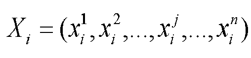


- Optionally, the parameter information further includes a minimum coiling length of a production apparatus for the plate, the decision variables further include a residual demand quantity and a completion quantity of finished product, and the constraints further include a fourth constraint corresponding to the minimum coiling length.
- Optionally, the plate comprises small plates of a number m indexed by i , wherein i = 1,2,...,m; and wherein the products to be processed have finished product specifications in total of a number n indexed by j, wherein j = 1,2,...,n; and wherein a layout vector of the i th small plate is set as


- Optionally, the plate is a silicon steel plate.
- Yet another embodiment of the present invention further discloses a production optimization method for nesting and shear cutting of a defective plate, including any one of the foregoing layout methods for nesting and shear cutting of a defective plate, and the step of finding out the layout modes of each small plate that satisfies the constraints includes: setting optimization objectives for nesting and shear cutting of the plate; establishing a model for nesting and shear cutting of the plate based on the decision variables, the constraints and the optimization objectives; and solving the model to obtain the layout modes.
- By utilizing the above technical solution, the production efficiency of the plate processing process can be improved by the production optimization method for nesting and shear cutting of a defective plate.
- Optionally, the optimization objectives include an average product-yield of small plates, and/or, a sum of the completed quantities of finished products.
- Optionally, the plate comprises small plates of a number m indexed by i, wherein i = 1,2,...,m; and wherein the products to be processed have finished product specifications in total of a number n indexed by j, wherein j = 1,2,...,n ; and wherein a layout vector of the ith small plate is set as


- The optimization objective is obtained by weight summing the first optimization objective and the second optimization objective.
- Optionally, the parameter information includes a length of small plate, and the production optimization method for nesting and shear cutting of a defective plate further comprises the following steps: issuing control instruction according to the electronic defect map, the parameter information and the layout mode; and performing nesting and shear cutting on the plate according to the control instruction.
- Yet another embodiment of the present invention further discloses a preprocessing system for nesting and shear cutting of a defective plate, comprising a processing unit for processing the plate by any one of the foregoing preprocessing methods for nesting and shear cutting of a defective plate.
- By utilizing the above technical solution, the scrap rate of plate processing can be reduced by the preprocessing system for nesting and shear cutting of a defective plate.
- Another embodiment of the present invention further discloses a layout system for nesting and shear cutting of a defective plate, comprising a processing unit for processing the plate by any one of the foregoing layout methods for nesting and shear cutting of a defective plate.
- By utilizing the above technical solution, the layout system for nesting and shear cutting of a defective plate can facilitate processing production of the plate.
- Another embodiment of the present invention further discloses a production optimization system for nesting and shear cutting of a defective plate, comprising: a processing unit used for a solution which uses any one of the foregoing production optimization methods for nesting and shear cutting of a defective plate; a control unit for receiving the solution transmitted from the processing unit, and issuing control instruction according to the solution; and a production apparatus for receiving the control instruction, and performing nesting and shear cutting on the plate according to the control instruction.
- By utilizing the above technical solution, the production efficiency of the plate processing process can be improved by the production optimization system for nesting and shear cutting of a defective plate.
- Another embodiment of the present invention further discloses a computing device, comprising: a processor for implementing various instructions; and a memory for storing a plurality of instructions for the processor to load and execute any one of the foregoing preprocessing methods for nesting and shear cutting of a defective plate.
- Another embodiment of the present invention further discloses a computing device, comprising: a processor for implementing various instructions; and a memory for storing a plurality of instructions for the processor to load and execute any one of the foregoing layout methods for nesting and shear cutting of a defective plate.
- Another embodiment of the present invention further discloses a computing device, comprising: a processor for implementing various instructions; and a memory for storing a plurality of instructions for the processor to load and execute any one of the production optimization methods for nesting and shear cutting of a defective plate.
- Another embodiment of the present invention further discloses a storage medium stored with a plurality of instructions for the processor to load and execute any one of the foregoing preprocessing methods for nesting and shear cutting of a defective plate.
- An embodiment of the present invention further discloses a storage medium stored with a plurality of instructions for the processor to load and execute any one of the foregoing layout methods for nesting and shear cutting of a defective plate.
- Another embodiment of the present invention discloses a storage medium stored with a plurality of instructions for the processor to load and execute any one of the production optimization methods for nesting and shear cutting of a defective plate.
-
-
FIG 1 shows a flow chart of a preprocessing method for nesting and shear cutting of a defective plate according to an embodiment of the present invention; -
FIG 2 shows a schematic diagram of an electronic defect map of a plate according to an embodiment of the present invention; -
FIG 3 shows a flow chart of step S2 of a preprocessing method for nesting and shear cutting of a defective plate according to an embodiment of the present invention; -
FIG 4 shows a schematic diagram of an electronic defect map of a plate according to another embodiment of the present invention; -
FIG 5 is a schematic diagram of partitioned regions of a plate according to an embodiment of the present invention; and -
FIG 6 is a schematic diagram of an electronic defect map of a plate according to another embodiment of the present invention. - The implementations of the present invention are illustrated by the following specific embodiments, and those skilled in the art may learn other advantages and features of the present invention easily from the following detailed description. Although the present invention will be described in conjunction with the preferred embodiments, it is not intended that the features of the present invention are limited to those embodiments. On the contrary, the present invention has been described in connection with the embodiments for the purpose of covering alternatives or modifications which may be extended based on the claims of the present invention. In the following description, numerous specific details are included to provide a thorough understanding of the present invention. The present invention may be implemented without these details. Moreover, some of the specific details have been omitted from the description in order not to disorder or obscure the focus of the present invention. It should be noted that, the embodiments and their features in the present invention may be combined with each other without conflict.
- It should be noted that, in this specification, similar reference signs and letters refer to similar items in the following figures, and thus, once an item is defined in a figure, it needs not be further defined and explained in subsequent figures.
- The terms "first," "second," and the like are used solely to distinguish one from another and are not to be construed as indicating or implying relative importance.
- To make the objectives, technical solutions and advantages of the present invention more apparent, the embodiments of the present invention will be described in detail with reference to the accompanying drawings.
- Referring to
FIG 1 , an embodiment of the present invention discloses a preprocessing method for nesting and shear cutting of a defective plate, comprising the following steps: S1: acquiring plate information of the plate, wherein the plate information includes defect information and plate dimension information; S2: making an electronic defect map based on the defect information and the plate dimension information, and partitioning out a region available for nesting and shear cutting; and S3: partitioning the plate to obtain small plates according to the region available for nesting and shear cutting. - In S1, the plate information may be derived from measurement, product specifications, written warranty, and the like, and may be obtained by writing, or may be obtained by scanning codes, and the like, which is not limited in the embodiment. In S2, the electronic defect map is made based on the defect information and the plate dimension information, and the region available for nesting and shear cutting is partitioned out. That is to say, in the embodiment, an electronic schematic diagram of a plate may be made according to the plate dimension information. For example, the electronic schematic diagram for the plate is drawn according to a certain proportion. Then the defect information is digitized according to the size and the position of the defect, and is marked on the electronic schematic diagram of the plate, so as to obtain the electronic defect map. After removing the region where the defect is located, the remaining of the plate is the region available for nesting and shear cutting. Without being bound to the embodiment, the electronic schematic diagram of the plate may be made by a computer, a mobile terminal, a cloud server, or the like, which all have data entry and processing functions. In S3, the plate is partitioned according to the region available for nesting and shear cutting, that is, the electronic defect map of the plate is partitioned to obtain small plates. Optionally, the preprocessing method for nesting and shear cutting of a defective plate further comprises: displaying the obtained schematic diagram of the plate after preprocessing, so that the manufacturer can intuitively know the position and the size of each small plate, and check whether the defect information is wrong. In the present embodiment, the small plates are obtained by partitioning the plates based on the electronic defect map made by the digitized defect information instead of cutting the plate directly, which can help determine the subsequent processing solution for the plate before the production, thus having high scientificity and can improve the production efficiency.
- In one embodiment, referring to
FIG 2 andFIG 5 , the plate is a steel plate having a width of 1100 millimeters and a length of 2000 meters. In the present embodiment, the plate is partitioned into four regions, namely a WS side (working side), a central WS side (central working side), a central DS side (central driving side) and a DS side (driving side), along a width direction (X direction shown inFIG 2 andFIG5 ), wherein the working side is a side for the worker to operate, and the driving side is a side where a drive motor is located. Along a length direction (Y direction shown inFIG 2 ) of the plate, the blade assembling place during actual processing of the plate is set as a starting point, that is, the 0-meter position in length. In other embodiments, the plate may be partitioned by other methods. The defect information of the steel plate includes: (1) a 0-150-meter full-width fold; (2) a hole with the diameter=14.96 millimeters in the 950-meter on central DS side; and (3) 0-50-millimeter edge damage in the 200-500-meter on DS side. It should be appreciated that, in other embodiments, the defect information may also include other contents, such as defect grades. Other methods may be also used to describe the defect, as long as the defect regions can be located on the plate according to the defect information. - Referring to
FIG 2 , the electronic defect map of the plate includes the aforementioned three defects. Because the length of the plate is far greater than the width of the plate, the plate needs to be shear cut into a plurality of small plates transversely, i.e., along the width direction of the plate in the actual processing process. Therefore, in the present embodiment, the plate is partitioned transversely along the width direction of the plate according to the region available for nesting and shear cutting shown by the electronic defect map, and the plate may be partitioned into two small plates A1 and A2 along dotted lines a1, a2 and a3. Referring to the region available for nesting and shear cutting, regarding defect (3) which is located at the edge in the width direction of the plate, it does not need to be considered during partitioning the plate as the small plates are obtained by partitioning the plate transversely in the embodiment. After partition of the small plates, defect (3) is located on the small plate A1, and can be considered when the small plate A1 is subjected to layout and nesting and shear cutting, so that the overall plate processing efficiency can be improved. Without being bound to the embodiment, the plate may be also partitioned into small plates longitudinally along the length direction of the plate according to the size of the plate in other embodiments. In the present embodiment, defects (1) and (2) have been eliminated during partition of the small plates, while defect (3) has been presented in the electronic defect map for facilitating timely removal when the small plates are subjected to layout and nesting and shear cutting. Therefore, it would not lead to unqualified finished product due to the presence of the defects in the subsequent processing process of the plate, which greatly reduces the scrap rate of the plate. Without being bound to the embodiment, in other embodiments, the type and size of the plate, as well as the number, size, type and the like of the defects may be different from those of the present embodiment. - By utilizing the above technical solution, the preprocessing method for nesting and shear cutting of a defective plate disclosed by the present embodiment can help fully consider the adverse effect of the defects in the subsequent processing of the plate and partition out a region available for nesting and shear cutting by making an electronic defect map, so that the plate is reasonably partitioned into small plates according to the positions provided by the region available for nesting and shear cutting. Therefore, the technical solution can help avoid unqualified finished products caused by the defects in the subsequent plate processing and reduce the scrap rate, thus further reducing the production cost in plate processing.
- Referring to
FIG 3 , another embodiment of the present invention discloses a preprocessing method for nesting and shear cutting of a defective plate. The defect information includes that of primitive defects. The step S2 of making the electronic defect map based on the defect information and the plate dimension information, and partitioning out the region available for nesting and shear cutting comprises: S21: making the electronic defect map based on the primitive defects and the plate dimension information; S22: obtaining all non-edge defects based on the primitive defects; S23: computing distances between every two adjacent non-edge defects along the length direction of the plate; S24: merging any two adjacent non-edge defects along the length direction into a customized defect when their distances are lower than or equal to a predetermined distance threshold; and S25: partitioning out the region available for nesting and shear cutting based on the primitive defects and the customized defect. - Referring to
FIG 3- FIG 5, in S21, the electronic defect map is made based on the primitive defects and the plate dimension information. In one embodiment, the plate is a steel plate with a width of 1100 millimeters and a length of 2000 meters, and the defect information of the plate is as shown in the following Table 1:Table 1 Serial number of defects Text description of defects Defect 1 0-150-meter full-width fold of grade 4 Defect 2Hole with a diameter=14.96 millimeters in the 950-meter on central DS side Defect 3 Hole with a diameter=11.74 millimeters in the 1000-meter on central WS side Defect 4 0-50-millimeter edge damage of grade 5 in the 200-500-meter on DS side Defect 5 0-70-millimeter frost descent of grade 4 in the 400-900-meter on DS side Defect 6 0-40-millimeter spot of grade 2 in the 1200-1600-meter on DS sideDefect 7 0-60-millimeter indentation of grade 3 in the 1100-1400-meter on WS sideDefect 8 0-50-millimeter frost descent of grade 4 in the 1500-1800-meter on WS side Defect 9 Full-width transverse stripe of grade 3 in the 1820-2000-meter - In the present embodiment, the plate is partitioned into four regions, i.e., a WS side (working side), a central WS side (central working side), a central DS side (central driving side), and a DS side (driving side) along its width direction (X direction shown in
FIG 4 to FIG 5 ). The width of each region may be equally or unequally partitioned. Without being bound to the embodiment, the specific width may be set according to the defect description. In the present embodiment, along a length direction (Y direction shown inFIG 4 to FIG 5 ) of the plate, a blade assembling place during actual processing of the plate is set as a starting point, that is, the position of 0-meter in length. In other embodiments, the number of regions, the partitioning method, and the width of each region may be adaptively set according to the description of the defects in the defect information. In the present embodiment, referring toFIG 4 , 9 primitive defects according to Table 1 are shown, and a corresponding electronic defect map can be obtained according to the plate dimension information. A corresponding region of each defect is illustrated by the shaded portion inFIG 4 . Optionally, each defect is represented in a digitized form with reference to the mode as shown in the following Table 2 regarding the digitization of defect 6 in aforementioned Table 1, so as to facilitate making of the electronic defect map.Table 2 Defect type Length position (starting point) Length position (end point) Width region Width position (starting point) Width position (end point) Defect grade spot 1200 1600 DS side 0 40 2 - In S22, all non-edge defects are derived from the primitive defects. In the present embodiment, the plate needs to be shear cut into a plurality of small plates transversely, namely, along the width direction of the plate. Therefore, in the present embodiment, the plate is partitioned transversely along the width direction of the plate according to the region available for nesting and shear cutting of the electronic defect map. The non-edge defects in the embodiment are defects located on the central WS side (central working side) or the central DS side (central driving side), and
defect 2 anddefect 3 are non-edge defects. In S23, the distances between every two adjacent non-edge defects are computed along the length direction of the plate. In the present embodiment, the distance is shown as d inFIG 4 , wherein d=1000-950=50 meters as the diameter of the hole is ignored for its too-small diameter. In S24, if the distances are lower than or equal to a predetermined distance threshold, the corresponding adjacent non-edge defects are merged into the customized defect along the length direction. - In some embodiments, the predetermined distance threshold is greater than or equal to a minimum coiling length of the production apparatus for the plate. The minimum coiling length is the minimum distance between two adjacent shear cutting positions in the length direction of the plate during the actual processing process of the plate when the plate is shear cut into small plates along the width direction of the plate, and the specific numerical values are different according to different requirements of production apparatus and process standards, which may be 500 meters or 300 meters, and the like, for example. In the present embodiment, if the predetermined distance threshold is 500 meters,
defect 2 anddefect 3 are then merged into a customized defect. In S25, a region available for nesting and shear cutting is partitioned based on the primitive defects and the customized defect. That is to say, the region available for nesting and shear cutting does not include the region betweendefect 2 anddefect 3, and the 950-to-1000-meter full-width region along the length direction of the steel plate is not subjected to nesting and shear cutting. Along dotted lines b1, b2, b3 and b4 inFIG 4 , the steel plate may be partitioned into two small plates B1 and B2. Without being bound to the embodiment, the predetermined distance threshold may be other values in other embodiments. - In the present embodiment, the plate partitioned after preprocessing can better meet the requirements of the production apparatus in the subsequent processing process by setting the distance threshold and merging the non-edge defects according to the predetermined distance threshold. Preferably, the predetermined distance threshold is equal to the minimum coiling length of the production apparatus for the plate, so that the partitioned plate can not only meet the requirements of the production apparatus, but also avoid unnecessary defect merging that waste the plate.
- It should be appreciated that, because the plate is different from the products to be processed, part of the primitive defects are acceptable for the products to be processed. At this point, quality evaluation may be performed on all the primitive defects, and the acceptable defects are released according to information such as type, grade, size and the position of the defects. Then, the electronic defect map is made or updated according to unacceptable defects, and the plate is partitioned into small plates finally. Preferably, the quality evaluation of the defects can be automatically carried out according to the plate information, the information of the products to be processed, customer requirements and the like recorded in a computer, a mobile terminal, a cloud server and the like that have data entry and processing functions, so as to improve production efficiency.
- Another embodiment of the present invention further discloses a layout method for nesting and shear cutting of a defective plate, comprising any one of the preprocessing methods for nesting and shear cutting of a defective plate in the foregoing embodiments. The layout method for nesting and shear cutting of a defective plate comprises the following steps: acquiring specification information of each finished product for the products to be processed; acquiring parameter information of each small plate; setting decision variables relating to layout modes of each small plate, and establishing the constraints among the decision variables, the specification information and the parameter information; and finding out the layout mode of each small plate that satisfies the constraints.
- In the present embodiment, the specification information and the parameter information only need to be acquired before finding out the layout mode, and there is not any sequential limitation or requirement between each other. Without being bound to the embodiment, the specification information may be acquired either before or after preprocessing for nesting and shear cutting of a defective plate. The specification information may include a width of finished product, a demand quantity of finished product and the like; the parameter information may include a width of small plate, a length of small plate and the like; the constraints may include a length constraint, a width constraint, a product-yield constraint and the like; and the specification information, the parameter information and the constraints may be set as needed, which is not limited herein by the embodiment.
- In the present embodiment, the layout mode of each small plate in the plate is found out by establishing the constraints, so that the scientificity is high, and it is convenient to obtain the solution of the whole plate according to the layout mode before nesting and shear cutting of the plate, which facilitates the processing of the plate, and is beneficial for more accurate and scientific nesting and shear cutting production of the plate.
- Another embodiment of the present invention discloses a layout method for nesting and shear cutting of a defective plate, wherein the specification information includes a width of finished product; the parameter information includes a width of small plate, a maximum defect width on the working side of small plate and a maximum defect width on the driving side of small plate; the decision variables include a strip number of each finished product specification on each small plate, and the constraints include a first constraint corresponding to the width of small plate.
- The layout method for nesting and shear cutting of a defective plate disclosed by the present embodiment is used for integrally planning the plate according to the products to be processed, and solving the layout modes of each small plate by establishing the first constraint involving the width of small plate, the maximum defect width on the working side of small plate, the maximum defect width on the driving side of small plate and the decision variables, so that processing production of the plate is facilitated. Moreover, the adverse effect of edge defects is fully considered, which prevents the unqualified finished products caused by the defects from being processed, so that the scrap rate in the subsequent processing process of the plate is greatly reduced.
- Another embodiment of the present invention discloses a layout method for nesting and shear cutting of a defective plate, which comprises small plates of a number m indexed by i, wherein i = 1,2,...,m; the products to be processed have finished product specifications in total of a number n indexed by j, wherein j = 1,2,...,n; a layout vector of the i th small plate is set as



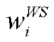
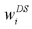
- In the present embodiment, the layout vector for each small plate may be found out according to formula (1). The layout vector is to represent the layout modes of each small plate, namely the strip number corresponding to each finished product on the small plate, into the form of mathematical vector. A corresponding layout mode can be obtained according to the layout vector. The blade assembling modes of each small plate in the subsequent processing process can be correspondingly obtained according to the layout modes and the width of edge defect, which facilitates subsequent processing production of the plate.
- In one embodiment, the plate is a steel plate with a width of 1100 millimeters and a length of 2000 meters. In an actual production process of the steel plate, it adopts a blade assembling mode that a plurality of disc blades are arranged along the width direction of the steel plate, and each small plate is cut into finished strips by the blades along the length direction of the steel plate. In the present embodiment, the product to be processed is a certain kind of transformer, and in the actual processing process, the steel plate needs to be processed into finished strips conforming to the transformer specifications required by the customer, after which the finished strips can be rolled into small coils and delivered to the customer. The finished product specifications of transformers are generally categorized by width, and finished strips with various width specifications are typically required to manufacture one transformer. In the present embodiment, the transformer has 18 kinds of finished product specifications corresponded thereto, and the width corresponding to each finished product specification is as shown in Table 3 below:
Table 3 Index of finished product Width of finished product wj Demand quantity of finished product lj Demand tolerance of finished product e j1 600 1868 3% 2 580 1587 3% 3 560 1689 3% 4 540 1442 3% 5 520 1658 3% 6 500 2430 3% 7 480 2466 3% 8 460 2500 3% 9 440 3967 3% 10 420 4264 3% 11 400 4139 3% 12 360 3507 3% 13 340 3536 3% 14 300 3348 3% 15 260 2242 3% 16 220 1555 3% 17 210 1224 3% 18 205 1385 3% - The width of finished product wj is a width value of the j th finished product after the product to be processed is completed. In the present embodiment, the unit of the finished product width wj is millimeter. Then according to the forgoing Table 3, w 1, ..., w 18 may be obtained.
- In the present embodiment, the defect information corresponding to the steel plate is the same as Table 1 in the foregoing embodiment. In particular,
defect 1 and defect 9 are full-width defects, which cannot be used for subsequent nesting and shear-cutting process. Referring toFIG 4 , the plate is partitioned transversely along dotted lines b1, b2, b3 and b4 in the width direction (X direction shown inFIG 4 ), so that the plate is partitioned into a small plate B1 and a small plate B2 in length, wherein the diameter of the hole is negligibly small and the distance betweendefect 2 anddefect 3 is too short, and thus, the two defects can be merged into a customized defect. - Then, the layout vector of each small plate is found out. The layout vector satisfies the above formula (1), that is, for each small plate, the sum of the total width corresponding to the finished product specification and the maximum defect widths on both sides is not greater than the width of small plate. In the present embodiment, the width of small plate is the same as the width of steel plate. It should be appreciated that, in some embodiments, only one Xi meets the conditions, and in other embodiments, there may be more than one Xi satisfying the conditions. Therefore, without being bound to the embodiment, there may be one or more selectable layout modes and corresponding blade assembling modes, and one of which may be selected as needed to perform actual processing.
- Another embodiment of the present invention discloses a layout method for nesting and shear cutting of a defective plate, and the parameter information further includes a margin default value, and the first constraint further comprises:


- In the present embodiment, the margin default value means that some plates, such as silicon steel plates, are prone to have uneven edge during the production process thereof, and the edge are not suitable for being processed into finished products, which may affect the quality of finished products. Therefore, it is desirable to reserve certain margin as scrap on the edge during the processing of the plate. Referring to
FIG 5 to FIG 6 , in the case that the plate is partitioned into small plates along the width direction (X direction shown inFIG 6 ) of the plate, and the small plates are shear cut along the length direction (Y direction shown inFIG 6 ) of the plate, the margin default value is the minimum width that needs to be reserved for the two sides of the plate, which can refer to two dotted lines c5 and c6 parallel to the Y direction inFIG 6 . In the present embodiment, when solving the layout mode, the requirement of the margin default value is considered, so that the production of products to be processed with higher requirements on the edge of the plate can be implemented better, which further reduces the scrap rate of the plate. - Referring to
FIG 6 , in one embodiment, the defect information corresponding to the plate is the same as the defect information in Table 1 in the foregoing embodiment, the plate is partitioned into a small plate C1 and a small plate C2 along dotted lines c1, c2, c3 and c4. With regard to small plate C1, there is no defects on the working side,


- Another embodiment of the present invention discloses a layout method for nesting and shear cutting of a defective plate, wherein the specification information further includes a demand quantity and a demand tolerance of finished product; the parameter information further includes a length of small plate; and the constraints further include a second constraint corresponding to the demand quantity of finished product.
- In the present embodiment, by introducing a second constraint, nesting and shear cutting of the plate can be better planned by the found-out layout mode, so that the capacity waste is reduced.
- Another embodiment of the present invention discloses a layout method for nesting and shear cutting of a defective plate. The plate comprises small plates of a number m indexed by i, wherein i = 1,2,...,m; the products to be processed have finished product specifications in total of a number n indexed by j, wherein j = 1,2,...,n; a layout vector of the ith small plate is set as


- In the present embodiment, with the support of formula (3), when products to be processed comprising multiple finished product specifications are needed to be processed from the plates, the circumstance that part of the finished product specifications are overproduced and other finished product specifications are underproduced can be mitigated, which better meets the requirement of actual production and facilitates the batch production of the products to be processed that have various specifications. The demand tolerance is the tolerance range of the product to be processed having specific finished product specification with respect to the demand quantity of the finished product. The value of the demand tolerance can be set as needed according to the type of the product to be processed and different requirements of customers. The demand tolerance is introduced to not only meet the requirements of customers on the products to be processed, but also facilitate the multiple-strip production of finished product specifications, and further facilitate shear cutting on the small plates.
- In one embodiment, the plate is a steel plate having a width of 1100 millimeters and a length of 2000 meters. The defect information corresponding to the steel plate is the same as Table 1 in the foregoing embodiment. In particular,
defect 1 and defect 9 are full-width defects, which both cannot be used for subsequent nesting and shear cutting processing. Referring toFIG 4 , the plate is partitioned transversely along dotted lines b1, b2, b3 and b4 in the width direction (X direction shown inFIG 4 ), so that the plate is partitioned into a small plate B1 and a small plate B2 in length, wherein the diameter of the hole is negligibly small, and the distance betweendefects defects 
- Another embodiment of the present invention discloses a layout method for nesting and shear cutting of a defective plate, wherein the parameter information further includes a product-yield, and the constraints further include a third constraint corresponding to the product-yield of each small plate.
- In the embodiment, by introducing the third constraint, the product-yield of each small plate may be constrained, so that the found-out layout mode satisfies the corresponding product-yield requirement.
- Another embodiment of the present invention discloses a layout method for nesting and shear cutting of a defective plate. The plate comprises small plates of a number m indexed by i, wherein i = 1,2,...,m; the products to be processed have finished product specifications in total of a number n indexed by j, wherein j = 1,2,...,n; a layout vector of the i th small plate is set as


- In the present embodiment, by setting a minimum product-yield P , the product-yield of each small plate corresponding to the found-out layout mode will not be lower than a predetermined value, so that the overall product-yield of the whole plate in the actual processing production process is greatly improved. In one embodiment, P is 80%, and in other embodiments, P may be other values. Without being bound to the embodiment, the specific numerical value of the minimum product-yield P may be set according to the type of the plate, the type of the product to be processed, and the like.
- Another embodiment of the present invention discloses a layout method for nesting and shear cutting of a defective plate. The parameter information further includes a minimum coiling length of a production apparatus for the plate, the decision variables further include a residual demand quantity of finished product and a completion quantity of finished product, and the constraint further includes a fourth constraint corresponding to the minimum coiling length.
- In the embodiment, by introducing the fourth constraint, the found-out layout mode facilitates nesting and shear cutting on the plate when applied, so that the production efficiency is improved.
- Another embodiment of the present invention discloses a layout method for nesting and shear cutting of a defective plate. The plate comprises small plates of a number m indexed by i, wherein i = 1,2,...,m; the products to be processed have finished product specifications in total of a number n indexed by j, wherein j = 1,2,...,n; a layout vector of the ith small plate is set as
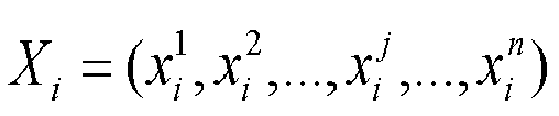



- In the present embodiment, when the production is performed on the whole plate according to the layout vector corresponding to each small plate, the residual demand quantity yj of each finished product, namely, an uncompleted value of each finished product, can be calculated by using formula (5). When yj is greater than 0, it represents that the demand quantity of the finished product specification j is not completed, at this point, zj =0, otherwise, zj =1. It should be appreciated that, in some embodiments, the demand tolerance may further include an upper limit of demand tolerance and a lower limit of demand tolerance. In this case, ej in formula (5) of the present embodiment is specifically the lower limit of the demand tolerance. A constant value M is set, and M is greater than or equal to a maximum value of the demand quantity of all finished product in the products to be processed. Formula (6) can constrain that if the demand quantity of a certain finished product is not completed, the corresponding residual demand quantity needs to be greater than or equal to the minimum coiling length N. Therefore, when one plate does not complete the demand quantity of a certain finished product in actual processing, the same production apparatus can be conveniently used to complete the residual demand of finished product using other plates for production, so that the production efficiency is improved.
- In one embodiment, the plate is shear cut into small plates along the width direction of the plate. At this point, the minimum coiling length is a minimum distance between two adjacent positions that is shear cut in the width direction of the plate, and the specific numerical value differs according to the requirements of the production apparatus and the process standard. For example, the specific numerical value may be 500 meters, and may also be 300 meters.
- Another embodiment of the present invention discloses a layout method for nesting and shear cutting of a defective plate, wherein the plate is a silicon steel plate. For example, with regard to shear cutting processing of a silicon steel product required for a transformer, the processing object is a coil of silicon steel, which will become a large rectangular silicon steel plate after it is unrolled. The silicon steel plate is processed into finished strips having transformer specifications required by customers, then the finished strips can be rolled into small coils and delivered to the customers. The finished specifications of the transformer refer to widths, and a plurality of width specifications are usually required for manufacturing one transformer. Silicon steel is a special product, and various defects such as holes, cracks, spots, color difference, roll marks, indentation, frost descent, stripes, folds, scratches and surface inclusions easily appear in the production process. Moreover, transformers have numerous finished product specifications and the silicon steel has different widths and different defect positions. In actual production, multiple finished product specifications of transformer are integrated together in one silicon steel plate, and the defective parts of the plate cannot be shear cut into finished products and provide to the customer. Therefore, during shear cutting, the defective parts need to be kept away to avoid providing the parts containing defects to the customers. The layout method disclosed by the present embodiment is particularly suitable for layout and subsequent processing of the silicon steel plate, which can greatly reduce the scrap rate of the silicon steel plate, improve the product-yield of the silicon steel plate, reduce the production cost, and improve the production efficiency.
- Another embodiment of the present invention further discloses a production optimization method for nesting and shear cutting of a defective plate, including any one of the layout methods for nesting and shear cutting of a defective plate in the foregoing embodiments. The step of finding out the layout mode of each small plate satisfying the constraint condition includes: setting optimization objectives for nesting and shear cutting of the plate; establishing a model for nesting and shear cutting of the plate according to the decision variables, the constraints and the optimization objectives; and solving the model to obtain the layout mode.
- In the present embodiment, a model is established by determining the decision variables, the constraints and the optimization objectives, so that a layout mode of each small plate can be quickly and efficiently found out. The production efficiency of the plate processing process can be improved, and the method is particularly suitable for a data processing device such as a computer. In one embodiment, the optimization objectives may be the product-yield. Without being bound to the embodiment, the optimization objectives may also be other objectives in other embodiments, which may be specifically set as needed. In one embodiment, the model is an integer programming model, and is solved by using a linear integer programming method. Without being bound to the embodiment, the model may also be solved by using other methods in other embodiments.
- In the present embodiment, by digitizing the defect information of the plate and replacing the traditional direct shear cutting mode, a mathematical model for nesting and shear cutting of the plate is established, so that the plate is processed optimally in actual nesting and shear cutting production, which has high scientificity to reduce the loss of raw materials and improve the production efficiency greatly.
- Another embodiment of the present invention further discloses a production optimization method for nesting and shear cutting of a defective plate. The optimization objectives include an average product-yield of the small plates, and/or, a sum of the completed quantities of the finished product. In the present embodiment, the optimization objective may be the average product-yield of the small plates, may also be the sum of the completed quantities of the finished product, or may further be a combined optimization objective formed thereby. It should be appreciated that, when the average product-yield of the small plates is taken as the optimization objective, the obtained layout mode can achieve a higher overall product-yield of the plate; when the sum of the completed quantities of the finished product is taken as the optimization objective, the finished product can be completed as much as possible in the actual production process of the plate; and when the combined optimization objective is formed by the aforementioned objectives, the product-yield and the completed quantity of the finished product can be balanced well, and the total production cost is reduced.
- Another embodiment of the present invention further discloses a production optimization method for nesting and shear cutting of a defective plate. The plate comprises small plates of a number m indexed by i, wherein i = 1,2,...,m; the products to be processed have finished product specifications in total of a number n indexed by j, wherein j = 1,2,...,n; a layout vector of the i th small plate is set as


- the sum of the completed quantities of the finished production is set as a second optimization obj ective:

- the optimization objective is obtained by weight summing the first optimization objective and the second optimization objective.
- In the present embodiment, the first optimization objective and the second optimization objective are combined and weight summed to obtain the optimization objective according to a certain proportion, so that the product-yield and the completed quantities of the finished product can be better balanced, and the total production cost is reduced. In one embodiment, whether the demand quantity of the finished product specification j is completed may be determined by calculating whether the residual demand quantity is greater than 0. It should be appreciated that, the respective weights of the two optimization objectives can be adjusted according to the parameter information, the importance, and the like. For example, in one embodiment, a weight ratio of obj1 with respect to obj2 may be 2:1, 3:1 and the like.
- Without being bound to the embodiment, the weights of obj1 and obj2 may be other values in other embodiments.
- Another embodiment of the present invention further discloses a production optimization method for nesting and shear cutting of a defective plate. The parameter information includes a length of the small plate. The production optimization method for nesting and shear cutting of a defective plate further comprises the following steps: issuing control instruction according to the electronic defect map, the parameter information and the layout mode; and performing nesting and shear cutting on the plate according to the control instruction.
- In the present embodiment, the dimension of the plate and the position and size of each small plate on the plate can be determined from the electronic defect map and the parameter information. Taking the process that the plate is shear cut into small plates along the width direction of the plate during plate processing, and then each small plate is cut into finished strips along the length direction of the plate as an example, the positions that need to use a transverse cutting device, such as a shear, in the length direction of the plate in the actual production process may be determined at this time, so as to cut the plate into various small plates along the width direction of the plate, and thus a transverse cutting solution of the plate is obtained. When processing each small plate, the positions that need to use a longitudinal cutting device, such as blades, in the width direction of the plate may be determined according to the electronic defect map and the layout modes of each small plate, so as to cut the small plates into finished strips corresponding to finished product in the length direction of the plate, and thus, a longitudinal-cutting blade assembling solution for each small plate is obtained, which further determine a nesting and shear cutting solution for the whole plate. At this point, control instruction corresponding to the nesting and shear cutting solution for the plate is issued, and then transverse cutting or longitudinal cutting is sequentially completed at corresponding positions of the plate according to the control instruction.
- According to the embodiment, the integral nesting and shear cutting solution for the plate is determined before the plate is processed, which facilitates the use of the device in the plate processing process, and improves the production efficiency of the plate in the actual processing process.
- The plate is set to comprise small plates of a number m indexed by i, wherein i = 1,2,...,m; the products to be processed have finished product specifications in total of a number n indexed by j, wherein j = 1,2,...,n; a layout vector of the i th small plate is set as


- In one embodiment, the plate is a silicon steel plate with a width of 1100 millimeters and a length of 2000 meters, and the corresponding defect information is shown in Table 1 in the foregoing embodiment. The primitive defects on the plate can be determined according to Table 1, and then the plate and the defects are digitized to make an electronic defect map. Referring to
FIG 5 to FIG 6 , in the embodiment, the plate is partitioned into four regions, namely a WS side (working side), a central WS side (central working side), a central DS side (central driving side), and a DS side (driving side) along the width direction (X direction shown inFIG 5 to FIG 6 ). Along a length direction (Y direction shown inFIG 5 and FIG 6 ) of the plate, a blade assembling place during actual processing of the plate is set as a starting point, that is, the 0-meter position in length. In other embodiments, the defects may be located by other methods. The plate has 9 primitive defects, which are unacceptable for the products to be processed. Referring toFIG 6 , 9 primitive defects according to Table 1 are shown, and a corresponding electronic defect map is obtained according to the plate dimension information, and a region corresponding to each defect is illustrated with reference to the shaded portion inFIG 6 . The present embodiment has a minimum coiling length of 500 meters. Theprimitive defect 2 and theprimitive defect 3 are merged into a customized defect along the length direction of the plate, then the plate is partitioned into two small plates C1 and C2 along dotted lines c1, c2, c3 and c4 according to the primitive defects and the customized defect. - In particular, small plate C1 has a length=950-150=800 meters, and small plate C2 has a length=1820-1000=820 meters. In the present embodiment, a margin default value s is set to be 20 millimeters, and the requirement on the reserved widths of the two sides of each small plate is calculated as follows: the requirement of the working side of small plate C1 =margin default value s=20 millimeters; and the requirement of the driving side of small plate C1 =max{margin default value s, wDS 1}=max {20,70}=70 millimeters. The requirement of the working side of small plate C2=max{margin default value s, wDS 2}=max{20,60}=60 millimeters; and the requirement of the driving side of small plate C2=max{margin default value s, wDS 2}=max{20,40}=40 millimeters.
- In the present embodiment, the product to be processed is a transformer which has 18 kinds of finished product specifications in total, and the corresponding specification information is shown in Table 3 in the foregoing embodiment. The present embodiment adopts a minimum product-yield P =80%, a constant value M =1000000, and the residual demand quantity of each finished product is


- In the embodiment, the average product-yield of the small plates is taken as a first optimization objective, while the sum of the completed quantity of the finished product is taken as a second optimization objective. The two objectives are weighted in a ratio of 1:1 and are combined to form an optimization objective. After solving, the following can be obtained:


- Therefore, the obtained nesting and shear cutting solution for the silicon steel plate is as follows:
- (1) Transverse cutting solution: the plate is transversely shear cut at the position of 150 meters, 950 meters, 1000 meters and 1820 meters, respectively, and thus, the plate is partitioned into a small plate C1 and a small plate C2.
- (2) Longitudinal-cutting blade assembling solution: the blade assembling solution of small plate C1: 580+220+205 (namely,
finished product specifications 2, 16 and 18 are nested together), the sum width=1005 millimeters, and the product-yield=91.36%; the blade assembling solution of small plate C2: 580+420 (namely,finished product specifications 2 and 10 are nested together), the sum width=1000 millimeters, and the product-yield=90.91%; completion statistics of finished products: the demand quantity offinished product specification 2 is completed. - Then, control instruction is issued according to the solution so as to complete nesting and shear cutting process of the silicon steel plate.
- The production optimization method above enables a high average product-yield of the silicon steel plate, and greatly reduce the scrap rate of the silicon steel plate. Additionally, more finished product can be completed, and the residual demand quantity of all uncompleted finished product are greater than the minimum coiling length, facilitating the production of the products to be processed. The solution of the whole plate is planned according to the optimization objective at first, then practical processing is performed, which provide high scientificity, lower production cost and improve the production efficiency.
- Another embodiment of the present invention further discloses a preprocessing system for nesting and shear cutting of a defective plate, comprising: a processing unit for processing the plate by any one of the preprocessing methods for nesting and shear cutting of a defective plate in the foregoing embodiments. The processing unit may be a computer, a single chip microcomputer, a mobile terminal, a server and other units that have data processing function.
- By utilizing the above technical solution, the preprocessing system for nesting and shear cutting of a defective plate can reduce the scrap rate in plate processing.
- Optionally, the preprocessing system further includes a display unit, and the display unit displays a schematic diagram of the preprocessed plate, so that manufacturers can conveniently check the defects.
- Another embodiment of the present invention further discloses a layout system for nesting and shear cutting of a defective plate, comprising: a processing unit for processing the plate by any one of the layout methods for nesting and shear cutting of a defective plate in the foregoing embodiments.
- By utilizing the above technical solution, the layout mode of each small plate can be obtained by the layout system for defective plates, which facilitates processing production of the plate. That is, a blade assembling mode in a production process may be determined according to the layout vector so as to carry out the subsequent nesting and shear cutting.
- Another embodiment of the present invention further discloses a production optimization system for nesting and shear cutting of a defective plate, comprising: a processing unit for processing the plate by the production optimization method for nesting and shear cutting of a defective plate in the foregoing embodiments; a control unit for receiving the solution transmitted from the processing unit, and issuing control instruction according to the solution; and a production apparatus for receiving the control instruction, and performing nesting and shear cutting to the plate according to the control instruction.
- By utilizing the above technical solution, the production efficiency in the plate processing process is improved by the production optimization system for nesting and shear cutting of a defective plate.
- Another embodiment of the present invention further discloses a computing device, comprising: a processor for implementing various instructions; and a memory for storing a plurality of instructions for the processor to load and execute any one of the preprocessing methods for nesting and shear cutting of a defective plate in the foregoing embodiments.
- Another embodiment of the present invention further discloses a computing device, comprising: a processor for implementing various instructions; and a memory for storing a plurality of instructions for the processor to load and execute any one of the layout methods for nesting and shear cutting of a defective plate in the foregoing embodiments.
- Another embodiment of the present invention further discloses a computing device, comprising: a processor for implementing various instructions; and a memory for storing a plurality of instructions for the processor to load and execute any one of the production optimization methods for nesting and shear cutting of a defective plate in the foregoing embodiments.
- Another embodiment of the present invention further discloses a storage medium, wherein the storage medium stores a plurality of instructions for the processor to load and execute any one of the preprocessing methods for nesting and shear cutting of a defective plate in the foregoing embodiments.
- Another embodiment of the present invention further discloses a storage medium, wherein the storage medium stores a plurality of instructions for the processor to load and execute any one of the layout methods for nesting and shear cutting of a defective plate in the foregoing embodiments.
- Another embodiment of the present invention further discloses a storage medium, wherein the storage medium stores a plurality of instructions for the processor to load and execute any one of the production optimization methods for nesting and shear cutting of a defective plate in the foregoing embodiments.
- The embodiments disclosed by the present application may be implemented in hardware, software, firmware, or a combination thereof. The embodiments of the present application may be implemented as computer programs or program codes executing on programmable systems including at least one processor, a storage system (including volatile and non-volatile memories and/or storage elements), at least one input device, and at least one output device. The program codes may be applied to input instructions to perform the functions described in the present application and generate output information. The output information may be applied to one or more output devices in a known manner. For purposes of the present application, a processing system includes any system having a processor such as a digital signal processor (DSP), a microcontroller, an application specific integrated circuit (ASIC), or a microprocessor.
- The program codes may be implemented in a high-level procedural language or object-oriented programming language to communicate with a processing system. The program codes may also be implemented in assembly language or machine language, if desired. In fact, mechanisms described in the present application are not limited in scope of any particular programming language. In any case, the language may be a compiled or interpreted language.
- In some cases, the disclosed embodiments may be implemented in hardware, firmware, software, or any combination thereof. The disclosed embodiments may also be implemented as instructions carried by or stored on one or more transitory or non-transitory machine-readable (for example, computer-readable) storage media, and the instructions may be read and executed by one or more processors. For example, the instructions may be distributed via a network or via other computer-readable media. Thus, the machine-readable medium may include any mechanism for storing or transmitting information in a machine-readable (for example, computer-readable) form, including, but not limited to, a floppy disk, an optical disk, a compact disk, a compact disc read-only memory (CD-ROM), a magneto-optical disk, a read-only memory (ROM), a random access memories (RAM), an erasable programmable read-only memory (EPROM), an electrically erasable programmable read-only memory (EEPROM), a magnetic or optical card, a flash memory, or a tangible machine-readable memory for transmitting information (for example, carrier waves, infrared signal digital signals, and the like) using the internet in the form of electricity, light, sound or other forms of propagated signals. Thus, a machine-readable medium includes any type of machine-readable medium suitable for storing or transmitting electronic instructions or information in a machine (for example, a computer)-readable form.
- In the drawings, some structure or method features may be shown in a particular arrangement and/or order. However, it is to be appreciated that such specific arrangement and/or ordering may not be required. Rather, in some embodiments, the features may be arranged in a manner and/or order different from that shown in the illustrative figures. In addition, the structure or method features included in a particular figure are not intended to imply that such features are required in all embodiments, and in some embodiments may not be included or may be combined with other features.
- It should be noted that, each module/unit mentioned in each device embodiment of the present application is a logical module/unit, and physically, one logical module/unit may be one physical module/unit, or a part of one physical module/unit, or may be implemented by a combination of multiple physical modules/units. The physical implementation manner of the logical module/unit itself is not the most important, and the combination of the functions implemented by the logical module/unit is the key to solve the technical problem proposed by the present application. Furthermore, in order to highlight the inventive part of the present application, the above device embodiments of the present application do not introduce modules/units which are not so closely related to solve the technical problems proposed by the present application, which does not indicate that there are no other modules/units in the above device embodiments.
- Although the present invention has been illustrated and described with reference to certain preferred embodiments of the present invention, it will be understood by those of ordinary skill in the art that the further detail description is made to the present application in combination with the specific embodiments, and the specific embodiments of the present invention are not to be construed as being limited thereto. Various changes in form and detail, including simple deductions or substitutions, may be made by those skilled in the art without departing from the spirit and scope of the present invention.
Claims (26)
- A preprocessing method for nesting and shear cutting of a defective plate, comprising the following steps:acquiring plate information of the plate, wherein the plate information includes defect information and plate dimension information;making an electronic defect map based on the defect information and the plate dimension information, and partitioning out a region available for nesting and shear cutting; andpartitioning the plate to obtain small plates according to the region available for nesting and shear cutting.
- The preprocessing method for nesting and shear cutting of a defective plate according to claim 1, wherein the defect information includes that of primitive defects; the step of making the electronic defect map based on the defect information and the plate dimension information, and partitioning out the region available for nesting and shear cutting comprises:making the electronic defect map based on the primitive defects and the plate dimension information;obtaining all non-edge defects based on the primitive defects;computing distances between every two adjacent non-edge defects along a length direction of the plate;merging any two adjacent non-edge defects into a customized defect along the length direction when their distance is lower than or equal to a predetermined distance threshold; andpartitioning out the region available for nesting and shear cutting based on the primitive defects and the customized defect.
- A layout method for nesting and shear cutting of a defective plate, comprising the preprocessing method for nesting and shear cutting of a defective plate according to claim 1 or 2, the layout method for nesting and shear cutting of a defective plate further comprising the following steps:acquiring specification information of each finished product for products to be processed;acquiring parameter information of each small plate;setting decision variables relating to layout modes of each small plate, and establishing constraints among the decision variables, the specification information and the parameter information; andfinding out layout modes for each small plate that satisfies the constraints.
- The layout method for nesting and shear cutting of a defective plate according to claim 3, wherein the specification information includes a width of finished product; and wherein the parameter information includes a width of small plate, a maximum defect width on the working side of small plate and a maximum defect width on the driving side of small plate; and wherein the decision variables include strip number of each finished product on each small plate, and the constraints include a first constraint corresponding to the width of small plate.
- The layout method for nesting and shear cutting of a defective plate according to claim 4, wherein the plate comprises small plates of a number m indexed by i, wherein i = 1,2,...,m; and wherein the products to be processed have finished product specifications in total of a number n indexed by j, wherein j = 1,2,..., n ; and wherein a layout vector of the i th small plate is set as


- The layout method for nesting and shear cutting of a defective plate according to claim 5, wherein the parameter information further includes a margin default value, and the first constraint further comprises:


- The layout method for nesting and shear cutting of a defective plate according to claim 4, wherein the specification information further includes a demand quantity of finished product and a demand tolerance of finished product; and wherein the parameter information further includes a length of small plate; and wherein the constraints further include a second constraint corresponding to the demand quantity of finished product.
- The layout method for nesting and shear cutting of a defective plate according to claim 7, wherein the plate comprises small plates of a number m indexed by i, wherein i = 1,2,...,m; and wherein the products to be processed have finished product specifications in total of a number n indexed by j, wherein j = 1,2,...,n; and wherein a layout vector of the ith small plate is set as


- The layout method for nesting and shear cutting of a defective plate according to claim 4, wherein the parameter information further includes a product-yield, and the constraints further include a third constraint corresponding to the product-yield of each small plate.
- The layout method for nesting and shear cutting of a defective plate according to claim 9, wherein the plate comprises small plates of a number m indexed by i, wherein i = 1,2,...,m; and wherein the products to be processed have finished product specifications in total of a number n indexed by j, wherein j = 1,2,...,n ; and wherein a layout vector of the ith small plate is set as


- The layout method for nesting and shear cutting of a defective plate according to claim 7, wherein the parameter information further includes a minimum coiling length of a production apparatus for the plate, the decision variables further include a residual demand quantity of finished product and a completion quantity of finished product, and the constraints further include a fourth constraint corresponding to the minimum coiling length.
- The layout method for nesting and shear cutting of a defective plate according to claim 11, wherein the plate comprises small plates of a number m indexed by i, wherein i = 1,2,...,m; and wherein the products to be processed have finished product specifications in total of a number n indexed by j, wherein j = 1,2,..., n ; and wherein a layout vector of the i th small plate is set as


 setting yj as real variable representing the residual demand quantity of the finished product specification j; setting zj as binary variable representing whether the demand quantity of the finished product specification j is completed, and if completed, the variable is taken as 1, otherwise, it is taken as 0; andsetting M as a constant value, wherein M ≥ max{l 1, l 2,..., l n};and wherein the fourth constraint comprises:

- The layout method for nesting and shear cutting of a defective plate according to any one of claims 3-12, wherein the plate is a silicon steel plate.
- A production optimization method for nesting and shear cutting of a defective plate, wherein the production optimization method comprises the layout method for nesting and shear cutting of a defective plate according to any one of claims 3-13, and wherein the step of finding out the layout modes of each small plate that satisfies the constraint further comprises:setting optimization objectives for nesting and shear cutting of the plate;establishing a model for nesting and shear cutting of the plate based on the decision variables, the constraints and the optimization objectives; andsolving the model to obtain the layout modes.
- The production optimization method for nesting and shear cutting of a defective plate according to claim 14, wherein the optimization objectives include an average product-yield of small plates, and/or, a sum of the completed quantities of finished product.
- The production optimization method for nesting and shear cutting of a defective plate according to claim 15, wherein the plate comprises small plates of a number m indexed by i, wherein i = 1,2,..., m; and wherein the products to be processed have finished product specifications in total of a number n indexed by j, wherein j = 1,2,...,n; and wherein a layout vector of the i th small plate is set as


 and wherein the average product-yield of small plates is set as a first optimization obj ective:
 the sum of the completed quantities of finished products is set as a second optimization obj ective:
 the optimization objective is obtained by weight summing the first optimization objective and the second optimization objective.
 - The production optimization method for nesting and shear cutting of a defective plate according to claim 14, wherein the parameter information includes a length of small plate, and the production optimization method for nesting and shear cutting of a defective plate further comprises the following steps:issuing control instruction according to the electronic defect map, the parameter information and the layout mode; andperforming nesting and shear cutting on the plate according to the control instruction.
- A preprocessing system for nesting and shear cutting of a defective plate, comprising:
a processing unit for processing the plate by the preprocessing method for nesting and shear cutting of a defective plate according to any one of claims 1-2. - A layout system for nesting and shear cutting of a defective plate, comprising:
a processing unit for processing the plate by the layout method for nesting and shear cutting of a defective plate according to any one of claims 3-13. - A production optimization system for nesting and shear cutting of a defective plate, comprising:a processing unit used for a solution which uses the production optimization method for nesting and shear cutting of a defective plate according to any one of claims 14-17 to obtain small plates;a control unit for receiving the solution transmitted from the processing unit and issuing control instruction according to the nesting solution; anda production apparatus for receiving the control instruction and performing nesting and shear cutting on the plate according to the control instruction.
- A computing device, comprising:a processor for implementing various instructions; anda memory for storing a plurality of instructions for the processor to load and execute the preprocessing method for nesting and shear cutting of a defective plate according to any one of claims 1-2.
- A computing device, comprising:a processor for implementing various instructions; anda memory for storing a plurality of instructions for the processor to load and execute the layout method for nesting and shear cutting of a defective plate according to any one of claims 3-13.
- A computing device, comprising:a processor for implementing various instructions; anda memory for storing a plurality of instructions for the processor to load and execute the production optimization method for nesting and shear cutting of a defective plate according to any one of claims 14-17.
- A storage medium, wherein the storage medium stores a plurality of instructions for the processor to load and execute the preprocessing method for nesting and shear cutting of a defective plate according to any one of claims 1-2.
- A storage medium, wherein the storage medium stores a plurality of instructions for the processor to load and execute the layout method for nesting and shear cutting of a defective plate according to any one of claims 3-13.
- A storage medium, wherein the storage medium stores a plurality of instructions for the processor to load and execute the production optimization method for nesting and shear cutting of a defective plate according to any one of claims 14-17.
Applications Claiming Priority (3)
| Application Number | Priority Date | Filing Date | Title |
|---|---|---|---|
| CN202010602833 | 2020-06-29 | ||
| CN202011636444.6A CN113926858B (en) | 2020-06-29 | 2020-12-31 | Pretreatment, layout and production optimization method of sheet cutting with defects |
| PCT/CN2021/101552 WO2022001752A1 (en) | 2020-06-29 | 2021-06-22 | Suit-cutting shearing preprocessing, layout and production optimization method for defective plate |
Publications (3)
| Publication Number | Publication Date |
|---|---|
| EP4156047A1 true EP4156047A1 (en) | 2023-03-29 |
| EP4156047A4 EP4156047A4 (en) | 2023-11-15 |
| EP4156047B1 EP4156047B1 (en) | 2025-02-12 |
Family
ID=79274122
Family Applications (1)
| Application Number | Title | Priority Date | Filing Date |
|---|---|---|---|
| EP21832761.7A Active EP4156047B1 (en) | 2020-06-29 | 2021-06-22 | Preprocessing, layout and production optimization methods for nesting and shear cutting of a defective plate |
Country Status (6)
| Country | Link |
|---|---|
| US (1) | US12561622B2 (en) |
| EP (1) | EP4156047B1 (en) |
| JP (1) | JP7545498B2 (en) |
| KR (1) | KR102877011B1 (en) |
| CN (1) | CN113926858B (en) |
| WO (1) | WO2022001752A1 (en) |
Families Citing this family (9)
| Publication number | Priority date | Publication date | Assignee | Title |
|---|---|---|---|---|
| CN114733799B (en) * | 2022-03-30 | 2024-01-12 | 杭州利珀科技有限公司 | An optical film roll cutting system and method |
| CN114904915A (en) * | 2022-04-28 | 2022-08-16 | 首钢智新迁安电磁材料有限公司 | Hot-rolled coil shearing control method and device |
| CN114841447B (en) * | 2022-05-13 | 2024-08-13 | 北京百度网讯科技有限公司 | Plate arrangement method and device |
| CN115759634B (en) * | 2022-11-18 | 2024-04-26 | 中南大学 | An efficient collaborative method for batch layout of rectangular plates |
| CN116561996B (en) * | 2023-04-26 | 2024-04-09 | 南京林业大学 | Rectangular part layout method based on electronic cutting saw cutting optimization |
| CN116629520B (en) * | 2023-04-27 | 2024-03-15 | 苏州大学 | Integrated control method for corrugated board double-cutter processing line |
| CN117151307B (en) * | 2023-10-30 | 2024-02-06 | 中国人民解放军战略支援部队航天工程大学 | Layout optimization method based on hybrid linear programming |
| CN119312992B (en) * | 2024-12-18 | 2025-03-18 | 南京佳盛机电器材制造有限公司 | A method and system for arranging irregular workpieces for surface scratched steel plates |
| CN120012997B (en) * | 2025-01-20 | 2025-07-29 | 浙江尤恩家用电器有限公司 | Washing machine roller stamping part production optimization method and system based on big data |
Family Cites Families (30)
| Publication number | Priority date | Publication date | Assignee | Title |
|---|---|---|---|---|
| US4221974A (en) * | 1979-02-02 | 1980-09-09 | The Bendix Corporation | Lumber inspection and optimization system |
| JPS563121A (en) * | 1979-06-15 | 1981-01-13 | Kawasaki Steel Corp | Hot shearing method for steel piece |
| JPS57202998A (en) * | 1981-06-04 | 1982-12-13 | Fujitsu Kiden Ltd | Layout method for press working strip |
| JPS6067020A (en) * | 1983-09-19 | 1985-04-17 | ユニオン・シデリュルジク・デュ・ノ−ル・エ・ド・レス・ド・ラ・フランス・パル・アブルビェ−ション・”ユジノル” | Method and device for manufacturing plate in predetermined size by treating coarse plate from rolling mill |
| JPH0885016A (en) * | 1994-09-13 | 1996-04-02 | Nisshin Steel Co Ltd | Method for alloting metallic band coil to contract, its device, picking method and device |
| JP3888072B2 (en) * | 2001-03-07 | 2007-02-28 | Jfeスチール株式会社 | Board assembling method |
| CN1584888A (en) * | 2004-06-07 | 2005-02-23 | 李德平 | Raw material intelligent blanking systems |
| US20060090319A1 (en) * | 2004-11-01 | 2006-05-04 | Howe Major K | Defect locating system for moving web |
| CN100440083C (en) * | 2006-06-27 | 2008-12-03 | 宝山钢铁股份有限公司 | On-line Optimal Shearing Method for Rolled Slabs |
| EP2470336B1 (en) * | 2009-08-25 | 2013-08-14 | Lasermax Roll Systems, Inc. | System and method for inline cutting and stacking of sheets for formation of books |
| WO2012000649A1 (en) * | 2010-06-28 | 2012-01-05 | Precitec Kg | Method for controlling a laser processing operation by means of a reinforcement learning agent and laser material processing head using the same |
| JP5482570B2 (en) * | 2010-08-20 | 2014-05-07 | 新日鐵住金株式会社 | Method and apparatus for manufacturing welded section steel |
| CN103593511A (en) * | 2013-10-27 | 2014-02-19 | 沈阳建筑大学 | Cutting-off and layout method for natural stone slabs with defects |
| CN104794491B (en) * | 2015-04-28 | 2018-01-23 | 重庆大学 | Based on the fuzzy clustering Surface Defects in Steel Plate detection method presorted |
| CN106312179B (en) * | 2015-06-19 | 2018-10-02 | 宝山钢铁股份有限公司 | A kind of on-line optimization cutting method with defect steel plate |
| KR101720265B1 (en) * | 2015-06-29 | 2017-03-27 | 윤태엽 | Cut process nesting system |
| PL3159093T3 (en) * | 2015-10-23 | 2018-12-31 | Bystronic Laser Ag | Method of controlling a laser cuting process in a high energy zone with interruption of the cutting process ; corresponding device and computer program |
| CN205733238U (en) * | 2016-05-09 | 2016-11-30 | 江阴兴澄特种钢铁有限公司 | A kind of optimization steel plate fixed size scissors cutting system |
| WO2018137753A1 (en) * | 2017-01-24 | 2018-08-02 | Siemens Product Lifecycle Management Software Inc. | Method and system for multiple views computer-aided-design including propagation of edit operations across views while ensuring constraints consistency |
| CN110288110B (en) * | 2018-03-19 | 2023-03-31 | 宝山钢铁股份有限公司 | Control optimization method for cutting production of OA (office automation) plate by suit |
| CN108764513B (en) * | 2018-04-02 | 2021-09-03 | 广东工业大学 | Two-stage-based rectangular optimization layout mixing method |
| US11468207B2 (en) * | 2018-05-21 | 2022-10-11 | Arizona Board Of Regents On Behalf Of The University Of Arizona | Systems and methods for simulation-based resource and layout optimization |
| WO2020033201A1 (en) * | 2018-08-10 | 2020-02-13 | Walmart Apollo, Llc | Systems and methods for high throughput cutting of sealing elements on packages |
| CN109614387B (en) * | 2018-10-24 | 2022-04-15 | 广州纬纶信息科技有限公司 | Rectangular piece layout method, electronic equipment and storage medium |
| DE102018133524A1 (en) * | 2018-12-21 | 2020-06-25 | Fraunhofer-Gesellschaft zur Förderung der angewandten Forschung e.V. | Method for providing board planning geometry data, method and laser flatbed machine for cutting out workpieces |
| CN110216319B (en) * | 2019-06-14 | 2021-01-05 | 北京科技大学 | An optimal shear control method for medium and thick plates based on online evaluation of surface quality |
| CN110598893A (en) * | 2019-07-18 | 2019-12-20 | 山东大学 | Multi-specification part layout method and system |
| CN110570038B (en) * | 2019-09-06 | 2022-07-22 | 福州大学 | Method and device for rectangular layout of irregular sheet with defects |
| CN110991755B (en) * | 2019-12-09 | 2022-04-19 | 广西大学 | An optimized blanking method for multi-size plate rectangular parts considering machinability |
| CN111275243B (en) * | 2020-01-08 | 2020-09-29 | 广东工业大学 | A two-dimensional irregular layout method for single-size sheet |
-
2020
- 2020-12-31 CN CN202011636444.6A patent/CN113926858B/en active Active
-
2021
- 2021-06-22 JP JP2022580124A patent/JP7545498B2/en active Active
- 2021-06-22 KR KR1020237000945A patent/KR102877011B1/en active Active
- 2021-06-22 WO PCT/CN2021/101552 patent/WO2022001752A1/en not_active Ceased
- 2021-06-22 EP EP21832761.7A patent/EP4156047B1/en active Active
- 2021-06-22 US US18/010,956 patent/US12561622B2/en active Active
Also Published As
| Publication number | Publication date |
|---|---|
| WO2022001752A1 (en) | 2022-01-06 |
| JP7545498B2 (en) | 2024-09-04 |
| US12561622B2 (en) | 2026-02-24 |
| KR102877011B1 (en) | 2025-10-27 |
| EP4156047A4 (en) | 2023-11-15 |
| CN113926858A (en) | 2022-01-14 |
| CN113926858B (en) | 2022-12-16 |
| EP4156047B1 (en) | 2025-02-12 |
| US20230237391A1 (en) | 2023-07-27 |
| JP2023531259A (en) | 2023-07-21 |
| KR20230022990A (en) | 2023-02-16 |
Similar Documents
| Publication | Publication Date | Title |
|---|---|---|
| EP4156047B1 (en) | Preprocessing, layout and production optimization methods for nesting and shear cutting of a defective plate | |
| US8725541B2 (en) | Systems and methods for rating and pricing insurance policies | |
| EP0733986A2 (en) | System and method for controlling the number of units of parts in an inventory | |
| EP3361438A1 (en) | Automatically prescribing total budget for marketing and sales resources and allocation across spending categories | |
| CN107392422A (en) | Evaluation of employee method and system | |
| US6226625B1 (en) | Value sharing method for determining pricing | |
| US20120046975A1 (en) | Rapid Insurance Market Segmentation and Savings Test | |
| KR20150116424A (en) | Production management method of printed matter using automation platform | |
| US20130179228A1 (en) | Systems and methods for improved calculation of coefficient for price sensitivity | |
| KR20190089478A (en) | Used car pricing system by big data based standard ratio of remaining value | |
| CN113076302A (en) | Power grid data management method, device, equipment and medium | |
| CN116050664A (en) | Garbage yield prediction method, system, electronic equipment and readable storage medium | |
| CN116090700A (en) | Coil stock cutting scheme determining method and device, computing equipment and medium | |
| CN120450587A (en) | Recommended warehouse method, device, electronic equipment and storage medium for steel coil storage | |
| CN116883005B (en) | Method for early warning and controlling network freight charge pad payment abnormality | |
| US20130226727A1 (en) | Application for buyers to optimize savings when shopping from multiple suppliers | |
| JP4622286B2 (en) | Profit / loss management information presentation method, profit / loss management information presentation device, and profit / loss management information presentation processing program | |
| CN110991873A (en) | Marketing resource adjustment method and device based on fluctuation influence factor | |
| Raafat et al. | Warehouse and distribution operations improvements: a case study | |
| Tenkir | The Effect of After-Sales Services on Customer Satisfaction in the Case of Lifan Motors | |
| CN117910831A (en) | Street view shop vehicle resource management system and method | |
| JP2956087B2 (en) | How to manage order instruction cards | |
| WO2024147352A1 (en) | Device for producing steel sheets, order/production/sales assistance device, method for ordering/ producing/selling steel sheets, and program for ordering/ producing /selling steel sheets | |
| CN117172885A (en) | Method and device for processing air ticket distribution | |
| CN118780834A (en) | A method and device for real-time dynamic price adjustment of online car-hailing orders |
Legal Events
| Date | Code | Title | Description |
|---|---|---|---|
| STAA | Information on the status of an ep patent application or granted ep patent |
Free format text: STATUS: THE INTERNATIONAL PUBLICATION HAS BEEN MADE |
|
| PUAI | Public reference made under article 153(3) epc to a published international application that has entered the european phase |
Free format text: ORIGINAL CODE: 0009012 |
|
| STAA | Information on the status of an ep patent application or granted ep patent |
Free format text: STATUS: REQUEST FOR EXAMINATION WAS MADE |
|
| 17P | Request for examination filed |
Effective date: 20221219 |
|
| AK | Designated contracting states |
Kind code of ref document: A1 Designated state(s): AL AT BE BG CH CY CZ DE DK EE ES FI FR GB GR HR HU IE IS IT LI LT LU LV MC MK MT NL NO PL PT RO RS SE SI SK SM TR |
|
| DAV | Request for validation of the european patent (deleted) | ||
| DAX | Request for extension of the european patent (deleted) | ||
| A4 | Supplementary search report drawn up and despatched |
Effective date: 20231018 |
|
| RIC1 | Information provided on ipc code assigned before grant |
Ipc: G06Q 10/04 20230101AFI20231012BHEP |
|
| GRAP | Despatch of communication of intention to grant a patent |
Free format text: ORIGINAL CODE: EPIDOSNIGR1 |
|
| STAA | Information on the status of an ep patent application or granted ep patent |
Free format text: STATUS: GRANT OF PATENT IS INTENDED |
|
| RIC1 | Information provided on ipc code assigned before grant |
Ipc: G06Q 10/04 20120101AFI20240508BHEP |
|
| INTG | Intention to grant announced |
Effective date: 20240607 |
|
| GRAJ | Information related to disapproval of communication of intention to grant by the applicant or resumption of examination proceedings by the epo deleted |
Free format text: ORIGINAL CODE: EPIDOSDIGR1 |
|
| STAA | Information on the status of an ep patent application or granted ep patent |
Free format text: STATUS: REQUEST FOR EXAMINATION WAS MADE |
|
| GRAP | Despatch of communication of intention to grant a patent |
Free format text: ORIGINAL CODE: EPIDOSNIGR1 |
|
| STAA | Information on the status of an ep patent application or granted ep patent |
Free format text: STATUS: GRANT OF PATENT IS INTENDED |
|
| INTC | Intention to grant announced (deleted) | ||
| INTG | Intention to grant announced |
Effective date: 20241008 |
|
| P01 | Opt-out of the competence of the unified patent court (upc) registered |
Free format text: CASE NUMBER: APP_63142/2024 Effective date: 20241127 |
|
| GRAS | Grant fee paid |
Free format text: ORIGINAL CODE: EPIDOSNIGR3 |
|
| GRAA | (expected) grant |
Free format text: ORIGINAL CODE: 0009210 |
|
| STAA | Information on the status of an ep patent application or granted ep patent |
Free format text: STATUS: THE PATENT HAS BEEN GRANTED |
|
| AK | Designated contracting states |
Kind code of ref document: B1 Designated state(s): AL AT BE BG CH CY CZ DE DK EE ES FI FR GB GR HR HU IE IS IT LI LT LU LV MC MK MT NL NO PL PT RO RS SE SI SK SM TR |
|
| REG | Reference to a national code |
Ref country code: GB Ref legal event code: FG4D |
|
| REG | Reference to a national code |
Ref country code: CH Ref legal event code: EP |
|
| REG | Reference to a national code |
Ref country code: DE Ref legal event code: R096 Ref document number: 602021026126 Country of ref document: DE |
|
| REG | Reference to a national code |
Ref country code: IE Ref legal event code: FG4D |
|
| REG | Reference to a national code |
Ref country code: NL Ref legal event code: MP Effective date: 20250212 |
|
| PG25 | Lapsed in a contracting state [announced via postgrant information from national office to epo] |
Ref country code: RS Free format text: LAPSE BECAUSE OF FAILURE TO SUBMIT A TRANSLATION OF THE DESCRIPTION OR TO PAY THE FEE WITHIN THE PRESCRIBED TIME-LIMIT Effective date: 20250512 |
|
| PG25 | Lapsed in a contracting state [announced via postgrant information from national office to epo] |
Ref country code: FI Free format text: LAPSE BECAUSE OF FAILURE TO SUBMIT A TRANSLATION OF THE DESCRIPTION OR TO PAY THE FEE WITHIN THE PRESCRIBED TIME-LIMIT Effective date: 20250212 |
|
| PG25 | Lapsed in a contracting state [announced via postgrant information from national office to epo] |
Ref country code: PL Free format text: LAPSE BECAUSE OF FAILURE TO SUBMIT A TRANSLATION OF THE DESCRIPTION OR TO PAY THE FEE WITHIN THE PRESCRIBED TIME-LIMIT Effective date: 20250212 |
|
| PGFP | Annual fee paid to national office [announced via postgrant information from national office to epo] |
Ref country code: DE Payment date: 20250617 Year of fee payment: 5 |
|
| PG25 | Lapsed in a contracting state [announced via postgrant information from national office to epo] |
Ref country code: ES Free format text: LAPSE BECAUSE OF FAILURE TO SUBMIT A TRANSLATION OF THE DESCRIPTION OR TO PAY THE FEE WITHIN THE PRESCRIBED TIME-LIMIT Effective date: 20250212 |
|
| PGFP | Annual fee paid to national office [announced via postgrant information from national office to epo] |
Ref country code: GB Payment date: 20250625 Year of fee payment: 5 |
|
| REG | Reference to a national code |
Ref country code: LT Ref legal event code: MG9D |
|
| PG25 | Lapsed in a contracting state [announced via postgrant information from national office to epo] |
Ref country code: NO Free format text: LAPSE BECAUSE OF FAILURE TO SUBMIT A TRANSLATION OF THE DESCRIPTION OR TO PAY THE FEE WITHIN THE PRESCRIBED TIME-LIMIT Effective date: 20250512 Ref country code: IS Free format text: LAPSE BECAUSE OF FAILURE TO SUBMIT A TRANSLATION OF THE DESCRIPTION OR TO PAY THE FEE WITHIN THE PRESCRIBED TIME-LIMIT Effective date: 20250612 |
|
| PG25 | Lapsed in a contracting state [announced via postgrant information from national office to epo] |
Ref country code: NL Free format text: LAPSE BECAUSE OF FAILURE TO SUBMIT A TRANSLATION OF THE DESCRIPTION OR TO PAY THE FEE WITHIN THE PRESCRIBED TIME-LIMIT Effective date: 20250212 |
|
| PGFP | Annual fee paid to national office [announced via postgrant information from national office to epo] |
Ref country code: LU Payment date: 20250528 Year of fee payment: 5 |
|
| PG25 | Lapsed in a contracting state [announced via postgrant information from national office to epo] |
Ref country code: HR Free format text: LAPSE BECAUSE OF FAILURE TO SUBMIT A TRANSLATION OF THE DESCRIPTION OR TO PAY THE FEE WITHIN THE PRESCRIBED TIME-LIMIT Effective date: 20250212 |
|
| PG25 | Lapsed in a contracting state [announced via postgrant information from national office to epo] |
Ref country code: LV Free format text: LAPSE BECAUSE OF FAILURE TO SUBMIT A TRANSLATION OF THE DESCRIPTION OR TO PAY THE FEE WITHIN THE PRESCRIBED TIME-LIMIT Effective date: 20250212 Ref country code: PT Free format text: LAPSE BECAUSE OF FAILURE TO SUBMIT A TRANSLATION OF THE DESCRIPTION OR TO PAY THE FEE WITHIN THE PRESCRIBED TIME-LIMIT Effective date: 20250612 |
|
| PG25 | Lapsed in a contracting state [announced via postgrant information from national office to epo] |
Ref country code: BG Free format text: LAPSE BECAUSE OF FAILURE TO SUBMIT A TRANSLATION OF THE DESCRIPTION OR TO PAY THE FEE WITHIN THE PRESCRIBED TIME-LIMIT Effective date: 20250212 Ref country code: GR Free format text: LAPSE BECAUSE OF FAILURE TO SUBMIT A TRANSLATION OF THE DESCRIPTION OR TO PAY THE FEE WITHIN THE PRESCRIBED TIME-LIMIT Effective date: 20250513 |
|
| REG | Reference to a national code |
Ref country code: AT Ref legal event code: MK05 Ref document number: 1766779 Country of ref document: AT Kind code of ref document: T Effective date: 20250212 |
|
| PG25 | Lapsed in a contracting state [announced via postgrant information from national office to epo] |
Ref country code: SE Free format text: LAPSE BECAUSE OF FAILURE TO SUBMIT A TRANSLATION OF THE DESCRIPTION OR TO PAY THE FEE WITHIN THE PRESCRIBED TIME-LIMIT Effective date: 20250212 |
|
| PG25 | Lapsed in a contracting state [announced via postgrant information from national office to epo] |
Ref country code: SM Free format text: LAPSE BECAUSE OF FAILURE TO SUBMIT A TRANSLATION OF THE DESCRIPTION OR TO PAY THE FEE WITHIN THE PRESCRIBED TIME-LIMIT Effective date: 20250212 |
|
| PG25 | Lapsed in a contracting state [announced via postgrant information from national office to epo] |
Ref country code: DK Free format text: LAPSE BECAUSE OF FAILURE TO SUBMIT A TRANSLATION OF THE DESCRIPTION OR TO PAY THE FEE WITHIN THE PRESCRIBED TIME-LIMIT Effective date: 20250212 |
|
| PG25 | Lapsed in a contracting state [announced via postgrant information from national office to epo] |
Ref country code: IT Free format text: LAPSE BECAUSE OF FAILURE TO SUBMIT A TRANSLATION OF THE DESCRIPTION OR TO PAY THE FEE WITHIN THE PRESCRIBED TIME-LIMIT Effective date: 20250212 |
|
| PG25 | Lapsed in a contracting state [announced via postgrant information from national office to epo] |
Ref country code: AT Free format text: LAPSE BECAUSE OF FAILURE TO SUBMIT A TRANSLATION OF THE DESCRIPTION OR TO PAY THE FEE WITHIN THE PRESCRIBED TIME-LIMIT Effective date: 20250212 |
|
| PG25 | Lapsed in a contracting state [announced via postgrant information from national office to epo] |
Ref country code: EE Free format text: LAPSE BECAUSE OF FAILURE TO SUBMIT A TRANSLATION OF THE DESCRIPTION OR TO PAY THE FEE WITHIN THE PRESCRIBED TIME-LIMIT Effective date: 20250212 Ref country code: CZ Free format text: LAPSE BECAUSE OF FAILURE TO SUBMIT A TRANSLATION OF THE DESCRIPTION OR TO PAY THE FEE WITHIN THE PRESCRIBED TIME-LIMIT Effective date: 20250212 |
|
| PG25 | Lapsed in a contracting state [announced via postgrant information from national office to epo] |
Ref country code: RO Free format text: LAPSE BECAUSE OF FAILURE TO SUBMIT A TRANSLATION OF THE DESCRIPTION OR TO PAY THE FEE WITHIN THE PRESCRIBED TIME-LIMIT Effective date: 20250212 |
|
| PG25 | Lapsed in a contracting state [announced via postgrant information from national office to epo] |
Ref country code: SK Free format text: LAPSE BECAUSE OF FAILURE TO SUBMIT A TRANSLATION OF THE DESCRIPTION OR TO PAY THE FEE WITHIN THE PRESCRIBED TIME-LIMIT Effective date: 20250212 |
|
| REG | Reference to a national code |
Ref country code: DE Ref legal event code: R097 Ref document number: 602021026126 Country of ref document: DE |
|
| PLBE | No opposition filed within time limit |
Free format text: ORIGINAL CODE: 0009261 |
|
| STAA | Information on the status of an ep patent application or granted ep patent |
Free format text: STATUS: NO OPPOSITION FILED WITHIN TIME LIMIT |
|
| REG | Reference to a national code |
Ref country code: CH Ref legal event code: L10 Free format text: ST27 STATUS EVENT CODE: U-0-0-L10-L00 (AS PROVIDED BY THE NATIONAL OFFICE) Effective date: 20251224 |
|
| 26N | No opposition filed |
Effective date: 20251113 |
|
| REG | Reference to a national code |
Ref country code: CH Ref legal event code: H13 Free format text: ST27 STATUS EVENT CODE: U-0-0-H10-H13 (AS PROVIDED BY THE NATIONAL OFFICE) Effective date: 20260127 |
|
| PG25 | Lapsed in a contracting state [announced via postgrant information from national office to epo] |
Ref country code: MC Free format text: LAPSE BECAUSE OF FAILURE TO SUBMIT A TRANSLATION OF THE DESCRIPTION OR TO PAY THE FEE WITHIN THE PRESCRIBED TIME-LIMIT Effective date: 20250212 |
|
| REG | Reference to a national code |
Ref country code: BE Ref legal event code: MM Effective date: 20250630 |
|
| PG25 | Lapsed in a contracting state [announced via postgrant information from national office to epo] |
Ref country code: IE Free format text: LAPSE BECAUSE OF NON-PAYMENT OF DUE FEES Effective date: 20250622 |
|
| PG25 | Lapsed in a contracting state [announced via postgrant information from national office to epo] |
Ref country code: BE Free format text: LAPSE BECAUSE OF NON-PAYMENT OF DUE FEES Effective date: 20250630 |
|
| PG25 | Lapsed in a contracting state [announced via postgrant information from national office to epo] |
Ref country code: FR Free format text: LAPSE BECAUSE OF NON-PAYMENT OF DUE FEES Effective date: 20250630 |
|
| PG25 | Lapsed in a contracting state [announced via postgrant information from national office to epo] |
Ref country code: CH Free format text: LAPSE BECAUSE OF NON-PAYMENT OF DUE FEES Effective date: 20250630 |