EP4155997A1 - Neutraining der intrusionsdetektion von fingerabdrücken in anwesenheit eines angreifers - Google Patents
Neutraining der intrusionsdetektion von fingerabdrücken in anwesenheit eines angreifers Download PDFInfo
- Publication number
- EP4155997A1 EP4155997A1 EP22184263.6A EP22184263A EP4155997A1 EP 4155997 A1 EP4155997 A1 EP 4155997A1 EP 22184263 A EP22184263 A EP 22184263A EP 4155997 A1 EP4155997 A1 EP 4155997A1
- Authority
- EP
- European Patent Office
- Prior art keywords
- distribution
- messages
- ecu
- unique
- attacker
- Prior art date
- Legal status (The legal status is an assumption and is not a legal conclusion. Google has not performed a legal analysis and makes no representation as to the accuracy of the status listed.)
- Granted
Links
- 238000001514 detection method Methods 0.000 title abstract description 5
- 238000012549 training Methods 0.000 title description 7
- 238000000034 method Methods 0.000 claims abstract description 87
- 238000004891 communication Methods 0.000 claims abstract description 49
- 238000009826 distribution Methods 0.000 claims description 205
- 238000003860 storage Methods 0.000 claims description 17
- 230000005540 biological transmission Effects 0.000 claims description 2
- 238000012545 processing Methods 0.000 description 39
- 230000015654 memory Effects 0.000 description 35
- 230000007704 transition Effects 0.000 description 15
- 239000004020 conductor Substances 0.000 description 14
- 230000008569 process Effects 0.000 description 8
- 230000002093 peripheral effect Effects 0.000 description 6
- 230000000694 effects Effects 0.000 description 4
- 238000005516 engineering process Methods 0.000 description 4
- 238000004519 manufacturing process Methods 0.000 description 4
- 230000000116 mitigating effect Effects 0.000 description 4
- 230000008859 change Effects 0.000 description 3
- 230000006870 function Effects 0.000 description 3
- 230000005291 magnetic effect Effects 0.000 description 3
- 230000003287 optical effect Effects 0.000 description 3
- 238000003491 array Methods 0.000 description 2
- 230000001413 cellular effect Effects 0.000 description 2
- 230000005294 ferromagnetic effect Effects 0.000 description 2
- 229920000642 polymer Polymers 0.000 description 2
- 230000000630 rising effect Effects 0.000 description 2
- 230000003068 static effect Effects 0.000 description 2
- 230000001360 synchronised effect Effects 0.000 description 2
- FMFKNGWZEQOWNK-UHFFFAOYSA-N 1-butoxypropan-2-yl 2-(2,4,5-trichlorophenoxy)propanoate Chemical compound CCCCOCC(C)OC(=O)C(C)OC1=CC(Cl)=C(Cl)C=C1Cl FMFKNGWZEQOWNK-UHFFFAOYSA-N 0.000 description 1
- 101100498818 Arabidopsis thaliana DDR4 gene Proteins 0.000 description 1
- 101000766246 Homo sapiens Probable E3 ubiquitin-protein ligase MID2 Proteins 0.000 description 1
- 102100026310 Probable E3 ubiquitin-protein ligase MID2 Human genes 0.000 description 1
- 230000004075 alteration Effects 0.000 description 1
- 230000006399 behavior Effects 0.000 description 1
- 230000001186 cumulative effect Effects 0.000 description 1
- 230000001351 cycling effect Effects 0.000 description 1
- 230000003247 decreasing effect Effects 0.000 description 1
- 230000001419 dependent effect Effects 0.000 description 1
- 238000005315 distribution function Methods 0.000 description 1
- 230000009977 dual effect Effects 0.000 description 1
- 230000007613 environmental effect Effects 0.000 description 1
- 230000036541 health Effects 0.000 description 1
- 238000010801 machine learning Methods 0.000 description 1
- 230000014759 maintenance of location Effects 0.000 description 1
- 238000013507 mapping Methods 0.000 description 1
- 238000005259 measurement Methods 0.000 description 1
- 238000012986 modification Methods 0.000 description 1
- 230000004048 modification Effects 0.000 description 1
- 238000012544 monitoring process Methods 0.000 description 1
- 230000006855 networking Effects 0.000 description 1
- 230000002265 prevention Effects 0.000 description 1
- 239000004065 semiconductor Substances 0.000 description 1
- 229910052710 silicon Inorganic materials 0.000 description 1
- 239000010703 silicon Substances 0.000 description 1
- 239000013598 vector Substances 0.000 description 1
- 230000000007 visual effect Effects 0.000 description 1
Images


Classifications
-
- G—PHYSICS
- G06—COMPUTING; CALCULATING OR COUNTING
- G06F—ELECTRIC DIGITAL DATA PROCESSING
- G06F21/00—Security arrangements for protecting computers, components thereof, programs or data against unauthorised activity
- G06F21/50—Monitoring users, programs or devices to maintain the integrity of platforms, e.g. of processors, firmware or operating systems
- G06F21/55—Detecting local intrusion or implementing counter-measures
- G06F21/552—Detecting local intrusion or implementing counter-measures involving long-term monitoring or reporting
-
- G—PHYSICS
- G06—COMPUTING; CALCULATING OR COUNTING
- G06F—ELECTRIC DIGITAL DATA PROCESSING
- G06F21/00—Security arrangements for protecting computers, components thereof, programs or data against unauthorised activity
- G06F21/50—Monitoring users, programs or devices to maintain the integrity of platforms, e.g. of processors, firmware or operating systems
- G06F21/55—Detecting local intrusion or implementing counter-measures
- G06F21/554—Detecting local intrusion or implementing counter-measures involving event detection and direct action
-
- G—PHYSICS
- G06—COMPUTING; CALCULATING OR COUNTING
- G06F—ELECTRIC DIGITAL DATA PROCESSING
- G06F21/00—Security arrangements for protecting computers, components thereof, programs or data against unauthorised activity
- G06F21/50—Monitoring users, programs or devices to maintain the integrity of platforms, e.g. of processors, firmware or operating systems
- G06F21/57—Certifying or maintaining trusted computer platforms, e.g. secure boots or power-downs, version controls, system software checks, secure updates or assessing vulnerabilities
- G06F21/577—Assessing vulnerabilities and evaluating computer system security
-
- G—PHYSICS
- G06—COMPUTING; CALCULATING OR COUNTING
- G06N—COMPUTING ARRANGEMENTS BASED ON SPECIFIC COMPUTATIONAL MODELS
- G06N5/00—Computing arrangements using knowledge-based models
- G06N5/02—Knowledge representation; Symbolic representation
- G06N5/022—Knowledge engineering; Knowledge acquisition
-
- H—ELECTRICITY
- H04—ELECTRIC COMMUNICATION TECHNIQUE
- H04L—TRANSMISSION OF DIGITAL INFORMATION, e.g. TELEGRAPHIC COMMUNICATION
- H04L63/00—Network architectures or network communication protocols for network security
- H04L63/14—Network architectures or network communication protocols for network security for detecting or protecting against malicious traffic
- H04L63/1408—Network architectures or network communication protocols for network security for detecting or protecting against malicious traffic by monitoring network traffic
- H04L63/1416—Event detection, e.g. attack signature detection
-
- H—ELECTRICITY
- H04—ELECTRIC COMMUNICATION TECHNIQUE
- H04L—TRANSMISSION OF DIGITAL INFORMATION, e.g. TELEGRAPHIC COMMUNICATION
- H04L63/00—Network architectures or network communication protocols for network security
- H04L63/14—Network architectures or network communication protocols for network security for detecting or protecting against malicious traffic
- H04L63/1408—Network architectures or network communication protocols for network security for detecting or protecting against malicious traffic by monitoring network traffic
- H04L63/1425—Traffic logging, e.g. anomaly detection
-
- H—ELECTRICITY
- H04—ELECTRIC COMMUNICATION TECHNIQUE
- H04W—WIRELESS COMMUNICATION NETWORKS
- H04W12/00—Security arrangements; Authentication; Protecting privacy or anonymity
- H04W12/12—Detection or prevention of fraud
- H04W12/121—Wireless intrusion detection systems [WIDS]; Wireless intrusion prevention systems [WIPS]
- H04W12/122—Counter-measures against attacks; Protection against rogue devices
-
- G—PHYSICS
- G06—COMPUTING; CALCULATING OR COUNTING
- G06F—ELECTRIC DIGITAL DATA PROCESSING
- G06F2221/00—Indexing scheme relating to security arrangements for protecting computers, components thereof, programs or data against unauthorised activity
- G06F2221/03—Indexing scheme relating to G06F21/50, monitoring users, programs or devices to maintain the integrity of platforms
- G06F2221/034—Test or assess a computer or a system
-
- G—PHYSICS
- G06—COMPUTING; CALCULATING OR COUNTING
- G06N—COMPUTING ARRANGEMENTS BASED ON SPECIFIC COMPUTATIONAL MODELS
- G06N20/00—Machine learning
Definitions
- Communication networks are implemented in a variety of modern systems, such as, automotive, bus, train, industrial vehicle, agricultural vehicle, ship, aircraft, spacecraft, manufacturing, industrial, medical device, health care systems, retail, etc.
- networking protocols are used to facilitate information communication between components in the system.
- an in-vehicle network like a CAN bus
- IVN in-vehicle network
- electronic control units e.g., microcontrollers, sensors, actuators, etc.
- identification of the electronic control unit (ECU) transmitting a message is important for an intrusion detection system (IDS) or an active attack prevention (AAP) system.
- IDS intrusion detection system
- AAP active attack prevention
- Modern intrusion detection systems use device fingerprinting, which typically relies on the physical characteristics of devices being fingerprinted.
- an IDS in a vehicle may leverage voltage characteristics of ECUs transmitting on IVN to generate a fingerprint for each ECU, which fingerprints can subsequently be used to identify ECUs transmitting on the IVN.
- fingerprints must necessarily be regenerated, which is often referred to as "retraining.” It is to be appreciated that where a malicious entity (“attacker”) is present, retraining is problematic as the attacker can mislead the retraining process.
- the present disclosure provides systems and methods for training and/or retraining fingerprints even in the presence of an attacker.
- ECUs can be fingerprinted based on their analog voltage waveform.
- analog waveform data e.g., data associated with various ECUs transmitting on a bus, or the like
- a number of histograms can be generated from the analog waveform data. These histograms can be separated into unique groups, which are then used to identify that messages are from a unique source.
- a density, using a kernel based density function (e.g., a probability density function (PDF), or the like) of the analog waveforms can be derived and subsequently unique distributions for individual ECUs can be identified based on a cumulative distribution function (CDF). Individual ECUs can be fingerprinted based on these CDFs.
- PDF probability density function
- the present disclosure provides that for each group of messages identified as originating from the same source (e.g., based on the CDFs, or the like) probable attack messages can be extrapolated and removed from the histogram to accurately complete a fingerprinting process, even in the presence of an attacker.
- present disclosure can be applied to fingerprint ECUs for a variety of communication busses, which can be implemented in many different contexts, such as, for example, industrial networks, vehicular networks, manufacturing networks, retail operation networks, warehousing networks, or the like.
- the present disclosure can be applied to fingerprint (or retrain fingerprints) for ECUs transmitting on an IVN (e.g., a CAN bus, or the like).
- an IVN e.g., a CAN bus, or the like.
- the ECU to be fingerprinted can comprise multiple ECUs for engine control, transmission, airbags, antilock braking, cruise control, electric power steering, audio systems, power windows, power doors, power mirror adjustment, battery, recharging systems for hybrid/electric cars, environmental control systems, auto start stop systems, blind spot monitoring, lane keeping assist systems, collision avoidance systems, and more complex systems in the case of autonomous, or semi-autonomous vehicles.
- vehicular networks are often used in this description as an example implementation, the claims are not limited to networks implemented in a vehicle but can be applied to many contexts.
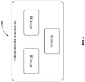
- FIG. 1A illustrates an example system 100, which can be implemented in a vehicle, such as, for example, an automobile, a motorcycle, an airplane, a boat, a personal watercraft, an all-terrain vehicle, or the like.
- System 100 includes a number of ECUs, for example, ECU 102a, ECU 102b, and ECU 102c are depicted.
- System 100 further includes ECU identification device 104.
- System 100 includes a communication bus 106, which can be a CAN bus, a FlexRay bus, a CAN FD bus, an automotive ethernet bus, or a local interconnected network (LIN) bus. Additionally, where implemented in contexts outside of the automotive space, the communication bus 106 can be a network bus adapted to the particular implementation, such as, for example, a communication network for manufacturing equipment, or the like.
- LIN local interconnected network
- each of ECU 102a, ECU 102b, and ECU 102c include circuitry arranged to generate messages and transmit the messages onto communication bus 106 and/or consume messages from communication bus 106.
- the depicted ECUs can be any of a variety of devices, such as, for example, sensor devices, actuator devices, microprocessor control devices, or the like.
- the ECUs include circuitry arranged to manipulate voltage levels on communication bus 106 (e.g., see FIG. 2 ) to communicate messages via the communication bus 106.
- system 100 includes ECU 102a, ECU 102b, and ECU 102c. This is done for clarity of presentation. However, in practice (e.g., in a modern automobile, or the like) hundreds of ECUs may be provided in system 100.
- ECUs are arranged to generate and/or consume messages, where the messages can include data or commands.
- ECUs can convey messages via communication bus 106.
- messages are depicted on communication bus 106.
- this figure depicts a number of messages (MSGs), such as, message 108a, message 108b, message 108c, and message 108d.
- MSGs messages
- the number of messages is depicted for purposes of clarity and ease of explanation.
- Many IVN standards do not provide for indicating source information on the bus.
- many broadcast communication networks e.g., IVN schemes, or the like
- messages do not have sufficient bandwidth for conventional cryptography techniques useful to indicate the source of messages, which indication can be used to authenticate the messages.
- messages e.g., message 108a, etc.
- messages often include a message identification (MIDI) (not shown) with which receivers can determine whether the message is relevant or not.
- MIDI message identification
- ECU identification device 104 arranged to train fingerprints or retrain fingerprints for ECUs 102a, 102b, and 102c even in the presence of an attacker (e.g., a malicious ECU, or the like) such that an AAP system or IDS can utilize the fingerprints to determine the authenticity of a source of a message, detect the present of an attacker, or the like.
- ECU identification device 104 includes processing circuitry 110, observation circuitry 112, and memory 114.
- Memory 114 includes instructions 116 (e.g., firmware, or the like) that can be executed by processing circuitry 110 and/or observation circuitry 112.
- observation circuitry 112 can observe voltage levels on communication bus 106, for example, at point 118.
- the observed voltage levels on communication bus 106 can be stored as raw analog voltages 120.
- processing circuitry 110 can execute instructions 116 to store voltages observed by observation circuitry 112 as raw analog voltages 120.
- Processing circuitry 110 can execute instructions 116 to generate densities 122 from raw analog voltages 120 and observed distribution 124 from densities 122. This is explained in greater detail below. However, in general, processing circuitry 110 can execute instructions 116 to generate a PDF (e.g., densities 122) from the analog waveforms (e.g., raw analog voltages 120) and generate a CDF (e.g., observed distribution 124) from the PDF.
- ECUs e.g., ECU 102a, ECU 102b, ECU 102c, etc.
- a fingerprint 126 comprising ECU IDs 128 and distributions 130 can be generated.
- processing circuitry 110 in executing instructions 116 can be arranged to generate fingerprint 126 by cycling through each ECU to observe voltages and generate unique distributions (e.g., distributions 130) and insert the distributions 130 along with an ECU identifier (e.g., ECU IDs 128) into the fingerprint 126.
- ECU identifier e.g., ECU IDs 1228
- fingerprint 126 can be used (e.g., by an IDS, or the like) to determine the authenticity of messages transmitted on communication bus 106.
- processing circuitry 110, in executing instructions 116 can compare the observed distribution 124 to distributions 130 from fingerprint 126 to determine an identity of an ECU sending the message (e.g., messages 108a, 108b, 108c, 108d, etc.).
- processing circuitry 110, in executing instructions 116 can determine the identity based on ECU IDs 128 associated with the distributions 130 from fingerprint 126.
- processing circuitry 110 in executing instructions 116 can compare the observed distribution 124 to distributions 130 using a minimum mean square error (MMSE) metric to match the observed distribution 124 to a distribution from the distributions 130. More specifically, processing circuitry 110 can execute instructions 116 to determine a distance between the observed distribution 124 and ones of distributions 130 from fingerprint 126. The distribution of the distributions 130 having the smallest distance may be identified as matching the observed distribution 124 and the source of the message associated with the observed distribution 124 can be identified based on ECU IDs 128. As another example, the distribution of the distributions 130 having the smallest distance less than a threshold value may be identified as matching the observed distribution 124.
- MMSE minimum mean square error
- memory 114 can comprise retraining data 132 including malicious frame count 134, attacker distribution 136, and authentic distribution 138.
- physical characteristics e.g., raw analog voltages 120, or the like
- Fingerprint 126 can be updated based on transmitted messages and their associated MID and observed physical characteristics (e.g., raw analog voltages 120).
- a determination as to whether malicious frames are encountered based on the retraining is made.
- a count of the number of malicious frames detected during retraining can be recorded in malicious frame count 134 and a mitigation method initiated where malicious frame count 134 is greater than a threshold (e.g., greater than 1, greater than or equal to 2, greater than or equal to 5, etc.).
- a threshold e.g., greater than 1, greater than or equal to 2, greater than or equal to 5, etc.
- FIG. 3 and method 300 An example of this retraining process and malicious frame detection is proved in FIG. 3 and method 300. Where malicious frames are detected during retraining, mitigation methods can be initiated, which are described in FIG. 4 and method 400 as well as FIG. 5 and method 500. In general however, an attacker distribution 136 and an authentic distribution 138 can be generated and fingerprint 126 updated based on the observed distribution 124, the attacker distribution 136, and the authentic distribution 138.
- Processing circuitry 110 can include any of a variety of processors, such as, for example, commercial central processing units, application specific integrated circuits, or the like. Processing circuitry 110 can be a microprocessor or a commercial processor and can include one or multiple processing core(s) and can also include cache.
- Observation circuitry 112 can include circuitry such as, analog to digital converters, voltage measurement circuitry, voltage waveform observation circuitry (e.g., oscilloscope circuitry, or the like) arranged to observe voltage transitions.
- circuitry such as, analog to digital converters, voltage measurement circuitry, voltage waveform observation circuitry (e.g., oscilloscope circuitry, or the like) arranged to observe voltage transitions.
- Memory 114 can be based on any of a wide variety of information storage technologies. For example, memory 114 can be based on volatile technologies requiring the uninterrupted provision of electric power or non-volatile technologies that do not require and possibly including technologies entailing the use of machine-readable storage media that may or may not be removable.
- each of these storages may include any of a wide variety of types (or combination of types) of storage devices, including without limitation, read-only memory (ROM), random-access memory (RAM), dynamic RAM (DRAM), Double-Data-Rate DRAM (DDR-DRAM), synchronous DRAM (SDRAM), static RAM (SRAM), programmable ROM (PROM), erasable programmable ROM (EPROM), electrically erasable programmable ROM (EEPROM), flash memory, polymer memory (e.g., ferroelectric polymer memory), ovonic memory, phase change or ferroelectric memory, silicon-oxide-nitride-oxide-silicon (SONOS) memory, magnetic or optical cards, one or more individual ferromagnetic disk drives, or a plurality of storage devices organized into one or more arrays (e.g., multiple ferromagnetic disk drives organized into a Redundant Array of Independent Disks array, or RAID array).
- memory 114 can include storage devices.
- FIG. 1B illustrates system 100, which can be system 100 of FIG. 1A in alternate detail.
- system 100 includes ECU 102a, ECU 102b, ECU 102c and observation circuitry 112.
- communication bus 106 can comprise a pair of conductors, such as conductor 140 and conductor 142.
- ECUs e.g., ECU 102a, ECU 102b, ECU 102c, or the like
- ECUs can communicate signals via conductor 140 and conductor 142
- observation circuitry 112 can observe analog voltages from conductor 140 and conductor 142 at point 118.
- densities 122 and observed distribution 124 for the analog voltages represented on both conductors (either individually or combined) of communication bus 106 can be generated.
- communication bus 106 can be an IVN comprising a CANH conductor (e.g., conductor 140) and a CANL conductor (e.g., conductor 142).
- FIG. 2 illustrates graph 200, showing example waveforms 202 undergoing voltage transitions.
- IVNs e.g., the CAN bus, or the like
- FIG. 2 depicts nominal recessive and dominant bus voltages for a CAN bus.
- the CAN bus is comprised of two conductors, as such two waveforms 202 are depicted.
- VCANH coupled to CANH a first voltage
- VCANL coupled to CANL a second voltage
- VCANH0 may be about 3.5 volts (V)
- VCANL0 may be about 1.5V.
- the term "about” may mean within a threshold value (e.g., 1%, or the like) and can be dependent upon the bus standard, which may dictate the tolerance.
- each waveform on the CAN bus can go through a number of voltage transitions.
- waveforms 202 can have a rising edge transition 204 or a falling edge transition 206.
- waveforms 202 can have a steady state transition 208 and a steady state transition 210. That is, waveforms 202 can have a steady state transition 210 for both the recessive state as well as a steady state transition 208 for the dominant state.
- an ECU To send a message (e.g., message 108a, message 108b, message 108c, message 108d, or the like) on the CAN bus, an ECU must cause a number of voltage transitions (e.g., rising edge transition 204, falling edge transition 206, steady state transition 208, and/or steady state transition 210) on the CAN bus to communicate bits indicating the contents of the message. Accordingly, during operation, analog voltage waveforms corresponding to messages (e.g., message 108a, message 108b, message 108c, etc.) can be observed on conductor(s) of communication bus 106.
- a number of voltage transitions e.g., rising edge transition 204, falling edge transition 206, steady state transition 208, and/or steady state transition 2
- FIG. 3 illustrates the method 300 for retraining a fingerprint in the presence of an attacker, in accordance with non-limiting example(s) of the present disclosure.
- Method 300 can be implemented by an IDS or AAP system, (e.g., by ECU identification device 104 of system 100, or the like) to retrain (or update) fingerprints of devices in the system after a context shift.
- Method 300 can begin at block 302.
- At block 302 "observe physical characteristics of a message transmitted on a communication bus by an ECU” physical characteristics (e.g., analog voltages, or the like) of a message transmitted on a communication bus by an ECU can be observed.
- Observation circuitry 112 can observe physical characteristics of one of message 108a or etc., transmitted by one of ECUs 102a, 102b, or 102c and can generate raw analog voltages 120 from the observation.
- processing circuitry 110 can execute instructions 116 to generate and/or update distributions 130 in fingerprint 126 from the raw analog voltages 120, densities 122, and observed distribution 124 of the message received at block 302.
- fingerprint 126 can include a distributions 130 for each ECU in system 100 or for each unique message (e.g., MID, or the like) observed on communication bus 106.
- processing circuitry 110 can execute instructions 116 to compare the raw analog voltages 120 for the message observed at block 302 to all distributions 130.
- decision block 308 "match within a threshold?" a determination of whether the observed physical characteristics matches any of the distributions 130 within a threshold amount.
- 110 can execute instructions 116 to compare raw analog voltages 120 (or rather observed distribution 124) to the distributions 130 and determine whether the observed distribution 124 is within a threshold distance (e.g., MSEE, or the like) to any one of the distributions 130.
- a threshold distance e.g., MSEE, or the like
- method 300 can continue to block 310 or decision block 312.
- method 300 can continue from decision block 308 to block 310 based on a determination that the physical characteristic for the message observed at block 302 is not within a threshold distance to any of the distributions 130.
- the message is unauthentic (or an attack message).
- the message could be transmitted by an ECU masquerading as another ECU, in which case the physical characteristics would not match the distributions 130 associated with the MID or ECU as the distributions 130 is based on the observed physical characteristics of both the authentic ECU and the attacker ECU.
- method 300 can continue from decision block 308 to decision block 312 based on a determination that the physical characteristic for the message observed at block 302 is within a threshold distance to any of the distributions 130. In such a case, it can be assumed that the message is authentic and retraining proceeds normally.
- a malicious frame counter can be incremented.
- processing circuitry 110 can execute instructions 116 to increment a counter (e.g., register in processing circuitry 110, data structure stored in memory 114, or the like) to store an indication of the number of malicious frames detected.
- method 300 can continue to decision block 312.
- decision block 312 "training size reached” a determination as to whether the number of frames needed retrain fingerprint 126 has been observed. For example, in some implementations, retraining (e.g., method 300) can continue until a specified number of messages are observed, until a specified time period has elapsed, or until a specified number of messages for each unique MID are observed.
- Processing circuitry 110 can execute instructions 116 to determine whether the "training size" has been reached, or rather whether retraining has sufficient data to be completed. From decision block 312, method 300 can continue to decision block 314 or return to block 302. In particular, method 300 can return to block 302 from decision block 312 based on a determination that the training size has not been reached while method 300 can continue to decision block 314 from decision block 312 based on a determination that the training size has been reached.
- malwareicious frame counter greater than or equal to a threshold a determination of whether the value indicated in the malicious frame counter is greater than or equal to a threshold value.
- the malicious frame count threshold can be 1, 2, 5, etc.
- ground truth shall be interpreted to mean mapping of unique ECU sigantures (e.g., voltage signatures, distributions 130, or the like) to message IDs (MIDs) with which the ECUs are transmitting, such as described with respect to fingerprint 126 abvoe.
- method 300 can end after decision block 314 based on a determination that the value in the malicious frame counter is not greater than or equal to the threshold malicious frame count while method 300 can proceed to method 400, to implement attack mitigation retraining, based on a determination that the value in the malicious frame counter is greater than or equal to the threshold malicious frame count.
- FIG. 4 illustrates the method 400 for retraining a fingerprint in the presence of an attacker, in accordance with non-limiting example(s) of the present disclosure.
- Method 400 can be implemented by an IDS or AAP system, (e.g., by ECU identification device 104 of system 100, or the like) to retrain (or update) fingerprints of devices in the system after a context shift and to mitigate the effects of the presence of an attacker on the retraining.
- Method 400 can begin at decision block 402 "attacker sending benign messages?" a determination as to whether the attacker ECU is also sending benign messages is made.
- processing circuitry 110 can execute instructions 116 to determine whether attacker distribution 136 matches one of distributions 130 from retrained fingerprint 126.
- distributions 130 from retrained fingerprint 126 will include a distribution associated with ECU 102c.
- method 400 can continue to method 500 or block 404.
- method 400 can continue from decision block 402 to method 500 based on a determination that the attacker is not sending benign messages while method 400 can continue from decision block 402 to block 408 based on a determination that the attacked is sending benign messages.
- equalized distributions from authentic message from the attacked ECU based on the number of expected authentic messages and the total number of received messages equalized distributions based on an observed physical characteristics of a number of authentic messages (e.g., one, two, three, etc.) and the number of expected authentic messages as well as the total number of messages is generated. For example, during retraining, the number of benign retraining messages or expected retraining messages for each ECU and/or each MID is known. Assume that ECU 102a transmits messages with unique MIDI and unique MID3 while ECU 102b transmits messages with unique MID 2.
- processing circuitry 110 can execute instructions 116 to generate an equalized distribution (not shown) from observed distribution 124 associated with an authentic message transmitted for a particular unique MID.
- processing circuitry 110 can execute instructions 116 to generate an equalized distribution by equalizing the observed distribution 124 for an authentic message with MIDI transmitted by ECU 102a to the number of expected authentic frames (e.g., four (4) continuing with the example above).
- processing circuitry 110 can execute instructions 116 to subtract the equalized distribution generated at block 402 from the distribution of distributions 130 associated with the MID generated during retraining of fingerprint 126 (e.g., during method 300, etc.) to generate attacker distribution 136.
- the attacker distribution 136 can be compared to distributions 130 from the retrained fingerprint 126.
- processing circuitry 110 can execute instructions 116 to compare distributions 130 with attacker distribution 136.
- decision block 410 "error between matches within a threshold?" a determination of whether the attacker distribution 136 matches any of the distributions 130 to within a threshold amount.
- 110 can execute instructions 116 to compare attacker distribution 136 to the distributions 130 and determine whether the attacker distribution 136 is within a threshold distance (e.g., MSEE, or the like) to any one of the distributions 130.
- a threshold distance e.g., MSEE, or the like
- method 400 can continue to block 412 or method 500.
- method 400 can continue from decision block 410 to block 412 based on a determination that the attacker distribution 136 is within a threshold distance to a one of the distributions 130.
- method 400 can continue from decision block 410 to method 500 based on a determination that the attacker distribution 136 is not within a threshold distance to any of the distributions 130.
- processing circuitry 110 can execute instructions 116 to add a flag, alert, or the like in fingerprint 126 indicating that the distribution of distributions 130 is associated with a malicious ECU.
- the overall IDS with which ECU identification device 104 is implemented can take other mitigation actions to prevent malicious behavior by that ECU.
- processing circuitry 110 can execute instructions 116 to subtract the attacker distribution 136 generated at block 404 from the distribution of distributions 130 associated with the MID (e.g., MIDI when continuing the example elaborated above, or the like) generated during retraining of fingerprint 126 (e.g., during method 300, etc.) to generate a retrained distributions 130 for the MID.
- method 400 can end with ground truth established.
- FIG. 5 illustrates the method 500 for retraining a fingerprint in the presence of an attacker, in accordance with non-limiting example(s) of the present disclosure.
- Method 500 can be implemented by an IDS or AAP system, (e.g., by ECU identification device 104 of system 100, or the like) to retrain (or update) fingerprints of devices in the system after a context shift and to mitigate the effects of the presence of an attacker on the retraining.
- method 500 can be implemented to mitigate the effects of an attacker on retaining where the attacker is not sending benign messages but only sends masqueraded messages.
- Method 500 can begin at block 502.
- block 502 "generate a first equalized distribution from a message with the masqueraded MID based on the number of expected authentic messages" a first equalized distribution based on an observed physical characteristics of a messagehaving an MID matching the masqueraded MID is generated based on the number of expected authentic messages.
- the message can be either authentic or malicious. That is, the message can originate from either the authentic ECU or the attack ECU.
- processing circuitry 110 can execute instructions 116 to generate an equalized distribution (not shown) from observed distribution 124 associated with a message transmitted (by either the authentic ECU or the attacker ECU) for a particular unique MID.
- processing circuitry 110 can execute instructions 116 to generate an equalized distribution by equalizing the observed distribution 124 for a message with MIDI transmitted by ECU 102a or ECU 102c to the number of expected authentic frames.
- processing circuitry 110 can execute instructions 116 to generate an equalized distribution (not shown) from observed distribution 124 associated with a message transmitted (by either the authentic ECU or the attacker ECU) for a particular unique MID.
- processing circuitry 110 can execute instructions 116 to generate an equalized distribution by equalizing the observed distribution 124 for a message with MIDI transmitted by ECU 102a or ECU 102c to the number of received attack frames.
- processing circuitry 110 can execute instructions 116 to subtract the equalized distributions generated at block 502 and block 504 from the distribution of distributions 130 associated with the MID generated during retraining of fingerprint 126 (e.g., during method 300, etc.) to generate a possible authentic distribution 138 and a possible attacker distribution 136.
- processing circuitry 110 can execute instructions 116 to compare observed distribution 124 from the message processed at block 502 and 504 with possible attacker distribution 136.
- decision block 510 "error less than a threshold?" a determination of whether the error between the attacker distribution 136 and observed distribution 124 is less than a threshold amount.
- 110 can execute instructions 116 to compare attacker distribution 136 to the observed distribution 124 and determine whether the attacker distribution 136 is within a threshold distance (e.g., MSEE, or the like) to observed distribution 124.
- a threshold distance e.g., MSEE, or the like
- method 500 can continue to block 512 or decision block 518.
- method 500 can continue from decision block 510to block 512 based on a determination that the attacker distribution 136 is not within a threshold distance to observed distribution 124. In such a case, it can be assumed that the message is not from the masquerading ECU (e.g., ECU 102c using the example above).
- method 500 can continue from decision block 510 to decision block 518 based on a determination that the attacker distribution 136 is within a threshold distance to observed distribution 124.
- processing circuitry 110 can execute instructions 116 to compare observed distribution 124 with the possible authentic distribution 138.
- decision block 514 "error less than a threshold?" a determination of whether the error between the possible authentic distribution 138 and observed distribution 124 is less than a threshold amount.
- 110 can execute instructions 116 to compare authentic distribution 138 to the observed distribution 124 and determine whether the authentic distribution 138 is within a threshold distance (e.g., MSEE, or the like) to observed distribution 124. From decision block 514, method 500 can continue to block 516 or decision block 518.
- a threshold distance e.g., MSEE, or the like
- method 500 can continue from decision block 514 to block 516 based on a determination that the authentic distribution 138 is within a threshold distance to observed distribution 124. In such a case, it can be assumed that the message is from the authentic ECU (e.g., ECU 102a using the example above). In the alternative case, method 500 can continue from decision block 514 to decision block 518 based on a determination that the authentic distribution 138 is not within a threshold distance to observed distribution 124.
- the fingerprint 126 can be updated based on the observed physical characteristics of the message.
- processing circuitry 110 can execute instructions 116 to update distributions 130 for the MID under attack based on the observed distribution 124 for the message selected at block 506. From block 516, method 500 can continue to decision block 518.
- decision block 518 "more messages?" a determination of whether more messages transmitted with the MID under attack (e.g., MIDI using the example above) need to be processed.
- processing circuitry 110 can execute instructions 116 to determine whether messages transmitted with the MID under attack need to be processed through method 500. That is, a fingerprint for a MID flagged as under attacked (e.g., MIDI using the example above) can be iteratively retrained based on all messages transmitted with that MID using method 500.
- method 500 can return to block 502 or can end the retraining with ground truth established.
- method 500 can end after decision block 518 based on a determination that there are not more messages to process while method 500 can return to 502, to process more messages, based on a determination that there are more messages to process.
- FIG. 6 illustrates an example of a storage device 600.
- Storage device 600 may comprise an article of manufacture, such as, any non-transitory computer readable medium or machine readable medium, such as an optical, magnetic or semiconductor storage.
- Storage device 600 may store various types of computer executable instructions 602, such as instructions to implement method 300, method 400, and/or method 500.
- Examples of a computer readable or machine readable storage medium may include any tangible media capable of storing electronic data, including volatile memory or non-volatile memory, removable or non-removable memory, erasable or non-erasable memory, writeable or rewriteable memory, and so forth.
- Examples of computer executable instructions may include any suitable type of code, such as source code, compiled code, interpreted code, executable code, static code, dynamic code, object-oriented code, visual code, and the like. The examples are not limited in this context.
- FIG. 7 illustrates an embodiment of a system 700.
- System 700 is a computer system with multiple processor cores such as a distributed computing system, supercomputer, high-performance computing system, computing cluster, mainframe computer, mini-computer, client-server system, personal computer (PC), workstation, server, portable computer, laptop computer, tablet computer, handheld device such as a personal digital assistant (PDA), or other device for processing, displaying, or transmitting information.
- Similar embodiments may comprise, e.g., entertainment devices such as a portable music player or a portable video player, a smart phone or other cellular phone, a telephone, a digital video camera, a digital still camera, an external storage device, or the like. Further embodiments implement larger scale server configurations.
- the system 700 may have a single processor with one core or more than one processor.
- processor refers to a processor with a single core or a processor package with multiple processor cores.
- the computing system 700 is representative of the components of the system 100. More generally, the computing system 700 is configured to implement all logic, systems, logic flows, methods, apparatuses, and functionality described herein with reference to FIG. 1A and FIG. 1B .
- a component can be, but is not limited to being, a process running on a processor, a processor, a hard disk drive, multiple storage drives (of optical and/or magnetic storage medium), an object, an executable, a thread of execution, a program, and/or a computer.
- a component can be, but is not limited to being, a process running on a processor, a processor, a hard disk drive, multiple storage drives (of optical and/or magnetic storage medium), an object, an executable, a thread of execution, a program, and/or a computer.
- an application running on a server and the server can be a component.
- One or more components can reside within a process and/or thread of execution, and a component can be localized on one computer and/or distributed between two or more computers. Further, components may be communicatively coupled to each other by various types of communications media to coordinate operations. The coordination may involve the uni-directional or bi-directional exchange of information. For instance, the components may communicate information in the form of signals communicated over the communications media. The information can be implemented as signals allocated to various signal lines. In such allocations, each message is a signal. Further embodiments, however, may alternatively employ data messages. Such data messages may be sent across various connections. Exemplary connections include parallel interfaces, serial interfaces, and bus interfaces.
- system 700 comprises a motherboard or system-on-chip(SoC) 702 for mounting platform components.
- Motherboard or system-on-chip(SoC) 702 is a point-to-point (P2P) interconnect platform that includes a first processor 704 and a second processor 706 coupled via a point-to-point interconnect 768 such as an Ultra Path Interconnect (UPI).
- P2P point-to-point
- UPI Ultra Path Interconnect
- the system 700 may be of another bus architecture, such as a multi-drop bus.
- each of processor 704 and processor 706 may be processor packages with multiple processor cores including core(s) 708 and core(s) 710, respectively.
- system 700 is an example of a two-socket (2S) platform
- other embodiments may include more than two sockets or one socket.
- some embodiments may include a four-socket (4S) platform or an eight-socket (8S) platform.
- Each socket is a mount for a processor and may have a socket identifier.
- platform refers to the motherboard with certain components mounted such as the processor 704 and chipset 732.
- Some platforms may include additional components and some platforms may only include sockets to mount the processors and/or the chipset.
- some platforms may not have sockets (e.g. SoC, or the like).
- the processor 704 and processor 706 can be any of various commercially available processors, including without limitation an Intel ® Celeron ® , Core ® , Core (2) Duo ® , Itanium ® , Pentium ® , Xeon ® , and XScale ® processors; AMD ® Athlon ® , Duron ® and Opteron ® processors; ARM ® application, embedded and secure processors; IBM ® and Motorola ® DragonBall ® and PowerPC ® processors; IBM and Sony ® Cell processors; and similar processors. Dual microprocessors, multi-core processors, and other multi processor architectures may also be employed as the processor 704 and/or processor 706. Additionally, the processor 704 need not be identical to processor 706.
- Processor 704 includes an integrated memory controller (IMC) 720 and point-to-point (P2P) interface 724 and P2P interface 728.
- the processor 706 includes an IMC 722 as well as P2P interface 726 and P2P interface 730.
- IMC 720 and IMC 722 couple the processors processor 704 and processor 706, respectively, to respective memories (e.g., memory 716 and memory 718).
- Memory 716 and memory 718 may be portions of the main memory (e.g., a dynamic random-access memory (DRAM)) for the platform such as double data rate type 3 (DDR3) or type 4 (DDR4) synchronous DRAM (SDRAM).
- DRAM dynamic random-access memory
- SDRAM synchronous DRAM
- the memories memory 716 and memory 718 locally attach to the respective processors (i.e., processor 704 and processor 706).
- the main memory may couple with the processors via a bus and shared memory hub.
- System 700 includes chipset 732 coupled to processor 704 and processor 706. Furthermore, chipset 732 can be coupled to storage device 750, for example, via an interface (I/F) 738.
- the I/F 738 may be, for example, a Peripheral Component Interconnect-enhanced (PCI-e).
- PCI-e Peripheral Component Interconnect-enhanced
- Processor 704 couples to a chipset 732 via P2P interface 728 and P2P 734 while processor 706 couples to a chipset 732 via P2P interface 730 and P2P 736.
- Direct media interface (DMI) 774 and DMI 776 may couple the P2P interface 728 and the P2P 734 and the P2P interface 730 and P2P 736, respectively.
- DMI 774 and DMI 776 may be a high-speed interconnect that facilitates, e.g., eight Giga Transfers per second (GT/s) such as DMI 3.0.
- GT/s Giga Transfers per second
- the processor 704 and processor 706 may interconnect via a bus.
- the chipset 732 may comprise a controller hub such as a platform controller hub (PCH).
- the chipset 732 may include a system clock to perform clocking functions and include interfaces for an I/O bus such as a universal serial bus (USB), peripheral component interconnects (PCIs), serial peripheral interconnects (SPIs), integrated interconnects (I2Cs), and the like, to facilitate connection of peripheral devices on the platform.
- the chipset 732 may comprise more than one controller hub such as a chipset with a memory controller hub, a graphics controller hub, and an input/output (I/O) controller hub.
- chipset 732 couples with a trusted platform module (TPM) 744 and UEFI, BIOS, FLASH circuitry 746 via I/F 742.
- TPM 744 is a dedicated microcontroller designed to secure hardware by integrating cryptographic keys into devices.
- the UEFI, BIOS, FLASH circuitry 746 may provide pre-boot code.
- chipset 732 includes the I/F 738 to couple chipset 732 with a high-performance graphics engine, such as, graphics processing circuitry or a graphics processing unit (GPU) 748.
- the system 700 may include a flexible display interface (FDI) (not shown) between the processor 704 and/or the processor 706 and the chipset 732.
- the FDI interconnects a graphics processor core in one or more of processor 704 and/or processor 706 with the chipset 732.
- ML accelerator 754 coupled to chipset 732 via I/F 738.
- ML accelerator 754 can be circuitry arranged to execute ML related operations (e.g., training, inference, etc.) for ML models.
- ML accelerator 754 can be arranged to execute mathematical operations and/or operands useful for machine learning.
- Various I/O devices 758 and display 752 couple to the bus 770, along with a bus bridge 756 which couples the bus 770 to a second bus 772 and an I/F 740 that connects the bus 770 with the chipset 732.
- the second bus 772 may be a low pin count (LPC) bus.
- LPC low pin count
- Various devices may couple to the second bus 772 including, for example, a keyboard 760, a mouse 762 and communication devices 764.
- an audio I/O 766 may couple to second bus 772.
- Many of the I/O devices 758 and communication devices 764 may reside on the motherboard or system-on-chip(SoC) 702 while the keyboard 760 and the mouse 762 may be add-on peripherals. In other embodiments, some or all the I/O devices 758 and communication devices 764 are add-on peripherals and do not reside on the motherboard or system-on-chip(SoC) 702.
- FIG. 8 illustrates an in-vehicle communication architecture 800 according to one or more embodiments of the disclosure.
- one or more vehicular devices, components, or circuits such as circuitry 802 and/or circuitry 804, may communicate with each other via a communication framework 806, which may be an in-vehicle network, such as a CAN bus, implemented to facilitate establishing ground truth in the presence of an attacker.
- a communication framework 806 may be an in-vehicle network, such as a CAN bus, implemented to facilitate establishing ground truth in the presence of an attacker.
- the in-vehicle communication architecture 800 includes various common communications elements, such as a transmitter, receiver, transceiver, and so forth. The embodiments, however, are not limited to implementation by the in-vehicle communication architecture 800. As shown in this figure, the vehicular circuitry 802 and circuitry 804 may each be operatively connected to one or more respective data devices, such as, data device 808 and/or data device 810 that can be employed to store information local to the respective circuitry 802 and/or circuitry 804, such as fingerprints, distributions, densities, voltage signals, or the like.
- circuitry 802 and circuitry 804 may be any suitable vehicular component, such as sensor, an ECU, microcontroller, microprocessor, processor, ASIC, field programmable gate array (FPGA), any electronic device, computing device, or the like.
- one or more computing devices containing at least a processor, memory, interfaces, etc. may be connected to the communication framework 806 in a vehicle.
- the communication framework 806 may implement any well-known communications techniques and protocols. As described above, the communication framework 806 may be implemented as a CAN bus protocol or any other suitable in-vehicle communication protocol. The communication framework 806 may also implement various network interfaces arranged to accept, communicate, and connect to one or more external communications networks (e.g., Internet). A network interface may be regarded as a specialized form of an input/output (I/O) interface.
- I/O input/output
- Network interfaces may employ connection protocols including without limitation direct connect, Ethernet (e.g., thick, thin, twisted pair 10/100/1000 Base T, and the like), token ring, wireless network interfaces, cellular network interfaces, IEEE 802.7a-x network interfaces, IEEE 802.16 network interfaces, IEEE 802.20 network interfaces, and the like. Further, multiple network interfaces may be used to engage with various communications network types.
- the communication framework 806 may employ both wired and wireless connections.
- processing circuitry discrete circuitry, application specific integrated circuits (ASICs), logic gates and/or single chip architectures, etc.
- ASICs application specific integrated circuits
- the features of the devices may be implemented using microcontrollers, programmable logic arrays and/or microprocessors or any combination of the foregoing where suitably appropriate.
- hardware, firmware and/or software elements may be collectively or individually referred to herein as “logic” or “circuit.”
- Some embodiments may be described using the expression “one embodiment” or “an embodiment” along with their derivatives. These terms mean that a particular feature, structure, or characteristic described in connection with the embodiment is included in at least one embodiment. The appearances of the phrase “in one embodiment” in various places in the specification are not necessarily all referring to the same embodiment. Further, some embodiments may be described using the expression “coupled” and “connected” along with their derivatives. These terms are not necessarily intended as synonyms for each other. For example, some embodiments may be described using the terms “connected” and/or “coupled” to indicate that two or more elements are in direct physical or electrical contact with each other. The term “coupled,” however, may also mean that two or more elements are not in direct contact with each other, but yet still co-operate or interact with each other.
Landscapes
- Engineering & Computer Science (AREA)
- Computer Security & Cryptography (AREA)
- Theoretical Computer Science (AREA)
- General Engineering & Computer Science (AREA)
- Software Systems (AREA)
- Computer Hardware Design (AREA)
- Physics & Mathematics (AREA)
- General Physics & Mathematics (AREA)
- Computing Systems (AREA)
- Signal Processing (AREA)
- Computer Networks & Wireless Communication (AREA)
- Artificial Intelligence (AREA)
- Computational Linguistics (AREA)
- Data Mining & Analysis (AREA)
- Evolutionary Computation (AREA)
- Mathematical Physics (AREA)
- Small-Scale Networks (AREA)
- Storage Device Security (AREA)
- Burglar Alarm Systems (AREA)
Applications Claiming Priority (1)
| Application Number | Priority Date | Filing Date | Title |
|---|---|---|---|
| US17/484,689 US20220012331A1 (en) | 2021-09-24 | 2021-09-24 | Re-Training Intrusion Detection Fingerprints in the Presence of an Attacker |
Publications (2)
| Publication Number | Publication Date |
|---|---|
| EP4155997A1 true EP4155997A1 (de) | 2023-03-29 |
| EP4155997B1 EP4155997B1 (de) | 2024-05-08 |
Family
ID=79172716
Family Applications (1)
| Application Number | Title | Priority Date | Filing Date |
|---|---|---|---|
| EP22184263.6A Active EP4155997B1 (de) | 2021-09-24 | 2022-07-12 | Neutraining der intrusionsdetektion von fingerabdrücken in anwesenheit eines angreifers |
Country Status (4)
| Country | Link |
|---|---|
| US (1) | US20220012331A1 (de) |
| EP (1) | EP4155997B1 (de) |
| CN (1) | CN115906071A (de) |
| NL (1) | NL2032846B1 (de) |
Citations (3)
| Publication number | Priority date | Publication date | Assignee | Title |
|---|---|---|---|---|
| JP2009130769A (ja) * | 2007-11-27 | 2009-06-11 | Autonetworks Technologies Ltd | 通信回路の異常検知装置 |
| WO2019026078A1 (en) * | 2017-08-02 | 2019-02-07 | Enigmatos Ltd. | SYSTEM AND METHOD FOR DETECTING MALWARE MATERIAL |
| CN111669352A (zh) * | 2019-03-08 | 2020-09-15 | 广州汽车集团股份有限公司 | 防拒绝服务攻击方法和装置 |
Family Cites Families (4)
| Publication number | Priority date | Publication date | Assignee | Title |
|---|---|---|---|---|
| WO2018013171A1 (en) * | 2016-07-15 | 2018-01-18 | The Regents Of The University Of Michigan | Identifying compromised electronic control units via voltage fingerprinting |
| US11503024B2 (en) * | 2019-12-06 | 2022-11-15 | The Mitre Corporation | Physical-layer identification of controller area network transmitters |
| US11720662B2 (en) * | 2020-08-14 | 2023-08-08 | Intel Corporation | Lightweight electronic control unit fingerprinting |
| US20220394045A1 (en) * | 2021-05-26 | 2022-12-08 | Marelli Europe S.P.A. | Method For Protection From Cyber Attacks To A Vehicle, And Corresponding Device |
-
2021
- 2021-09-24 US US17/484,689 patent/US20220012331A1/en active Pending
-
2022
- 2022-07-12 EP EP22184263.6A patent/EP4155997B1/de active Active
- 2022-08-24 CN CN202211018326.8A patent/CN115906071A/zh active Pending
- 2022-08-24 NL NL2032846A patent/NL2032846B1/en active
Patent Citations (3)
| Publication number | Priority date | Publication date | Assignee | Title |
|---|---|---|---|---|
| JP2009130769A (ja) * | 2007-11-27 | 2009-06-11 | Autonetworks Technologies Ltd | 通信回路の異常検知装置 |
| WO2019026078A1 (en) * | 2017-08-02 | 2019-02-07 | Enigmatos Ltd. | SYSTEM AND METHOD FOR DETECTING MALWARE MATERIAL |
| CN111669352A (zh) * | 2019-03-08 | 2020-09-15 | 广州汽车集团股份有限公司 | 防拒绝服务攻击方法和装置 |
Also Published As
| Publication number | Publication date |
|---|---|
| EP4155997B1 (de) | 2024-05-08 |
| NL2032846A (en) | 2023-03-29 |
| US20220012331A1 (en) | 2022-01-13 |
| NL2032846B1 (en) | 2023-08-04 |
| CN115906071A (zh) | 2023-04-04 |
Similar Documents
| Publication | Publication Date | Title |
|---|---|---|
| US20230342450A1 (en) | Lightweight electronic control unit fingerprinting | |
| EP4064620A1 (de) | Gesteuerter nachrichtenfehler für eine nachricht und elektronische steuereinheitsabbildung | |
| EP4109786A1 (de) | Signal-rausch-verhältnisbereichskonsistenzprüfung für radargeisterzielerfassung | |
| EP3971746A1 (de) | Spekulative und beschleunigte klassifikation basierend auf unvollständigen merkmalssätzen | |
| EP3955121A1 (de) | Verfahren, vorrichtung und computerlesbarer speicher zur identifizierung eines elektronischen steuergeräts (ecu) an einem kommunikationsbus | |
| EP4155997B1 (de) | Neutraining der intrusionsdetektion von fingerabdrücken in anwesenheit eines angreifers | |
| US20210320933A1 (en) | Post-gateway bus-off attack mitigation | |
| EP3972217A1 (de) | Ml-basierter spannungsfingerabdruck für ground truth und gesteuerten nachrichtenfehler für nachricht und ecu-mapping für can-bus | |
| EP4109816B1 (de) | Kontextbasierte reaktion auf angriffe gegen autonome systeme | |
| EP3955192A1 (de) | Kontinuierliche integritätsüberwachung für autonome transportdienste (maas) | |
| US11966503B2 (en) | Glitch attack mitigation for in-vehicle networks | |
| US12000957B2 (en) | Range doppler consistency check for radar ghost target detection | |
| US20210318414A1 (en) | Range Doppler Consistency Check for Radar Ghost Target Detection | |
| US20200117794A1 (en) | Reestablishing voltage profiles of electronic control units after reset |
Legal Events
| Date | Code | Title | Description |
|---|---|---|---|
| PUAI | Public reference made under article 153(3) epc to a published international application that has entered the european phase |
Free format text: ORIGINAL CODE: 0009012 |
|
| STAA | Information on the status of an ep patent application or granted ep patent |
Free format text: STATUS: THE APPLICATION HAS BEEN PUBLISHED |
|
| AK | Designated contracting states |
Kind code of ref document: A1 Designated state(s): AL AT BE BG CH CY CZ DE DK EE ES FI FR GB GR HR HU IE IS IT LI LT LU LV MC MK MT NL NO PL PT RO RS SE SI SK SM TR |
|
| STAA | Information on the status of an ep patent application or granted ep patent |
Free format text: STATUS: REQUEST FOR EXAMINATION WAS MADE |
|
| 17P | Request for examination filed |
Effective date: 20230918 |
|
| RBV | Designated contracting states (corrected) |
Designated state(s): AL AT BE BG CH CY CZ DE DK EE ES FI FR GB GR HR HU IE IS IT LI LT LU LV MC MK MT NL NO PL PT RO RS SE SI SK SM TR |
|
| GRAP | Despatch of communication of intention to grant a patent |
Free format text: ORIGINAL CODE: EPIDOSNIGR1 |
|
| STAA | Information on the status of an ep patent application or granted ep patent |
Free format text: STATUS: GRANT OF PATENT IS INTENDED |
|
| INTG | Intention to grant announced |
Effective date: 20231201 |
|
| GRAS | Grant fee paid |
Free format text: ORIGINAL CODE: EPIDOSNIGR3 |
|
| GRAA | (expected) grant |
Free format text: ORIGINAL CODE: 0009210 |
|
| STAA | Information on the status of an ep patent application or granted ep patent |
Free format text: STATUS: THE PATENT HAS BEEN GRANTED |
|
| AK | Designated contracting states |
Kind code of ref document: B1 Designated state(s): AL AT BE BG CH CY CZ DE DK EE ES FI FR GB GR HR HU IE IS IT LI LT LU LV MC MK MT NL NO PL PT RO RS SE SI SK SM TR |
|
| REG | Reference to a national code |
Ref country code: GB Ref legal event code: FG4D |
|
| REG | Reference to a national code |
Ref country code: CH Ref legal event code: EP |
|
| P01 | Opt-out of the competence of the unified patent court (upc) registered |
Effective date: 20240417 |
|
| REG | Reference to a national code |
Ref country code: DE Ref legal event code: R096 Ref document number: 602022003319 Country of ref document: DE |