EP4155795A1 - Boîtier de raccordement optique intelligent - Google Patents
Boîtier de raccordement optique intelligent Download PDFInfo
- Publication number
- EP4155795A1 EP4155795A1 EP22192804.7A EP22192804A EP4155795A1 EP 4155795 A1 EP4155795 A1 EP 4155795A1 EP 22192804 A EP22192804 A EP 22192804A EP 4155795 A1 EP4155795 A1 EP 4155795A1
- Authority
- EP
- European Patent Office
- Prior art keywords
- box
- housing
- network
- interventions
- connection box
- Prior art date
- Legal status (The legal status is an assumption and is not a legal conclusion. Google has not performed a legal analysis and makes no representation as to the accuracy of the status listed.)
- Withdrawn
Links
Images
Classifications
-
- G—PHYSICS
- G02—OPTICS
- G02B—OPTICAL ELEMENTS, SYSTEMS OR APPARATUS
- G02B6/00—Light guides; Structural details of arrangements comprising light guides and other optical elements, e.g. couplings
- G02B6/44—Mechanical structures for providing tensile strength and external protection for fibres, e.g. optical transmission cables
- G02B6/4439—Auxiliary devices
- G02B6/444—Systems or boxes with surplus lengths
- G02B6/4441—Boxes
-
- G—PHYSICS
- G01—MEASURING; TESTING
- G01K—MEASURING TEMPERATURE; MEASURING QUANTITY OF HEAT; THERMALLY-SENSITIVE ELEMENTS NOT OTHERWISE PROVIDED FOR
- G01K11/00—Measuring temperature based upon physical or chemical changes not covered by groups G01K3/00, G01K5/00, G01K7/00 or G01K9/00
-
- H—ELECTRICITY
- H02—GENERATION; CONVERSION OR DISTRIBUTION OF ELECTRIC POWER
- H02G—INSTALLATION OF ELECTRIC CABLES OR LINES, OR OF COMBINED OPTICAL AND ELECTRIC CABLES OR LINES
- H02G3/00—Installations of electric cables or lines or protective tubing therefor in or on buildings, equivalent structures or vehicles
- H02G3/02—Details
- H02G3/08—Distribution boxes; Connection or junction boxes
Definitions
- the present invention relates to an intelligent optical connection box.
- the invention belongs to the field of optical fiber telecommunications networks.
- Fiber optic telecommunications networks include, in particular, fiber optic cables and optical connection boxes.
- junction boxes can be installed outdoors or in buildings. They ensure the protection of optical fibres, splices and connections.
- connection boxes When they are installed outdoors, in particular in a pull chamber or on a pole, the connection boxes are subject to the vagaries of the weather. Water infiltration can partially or totally degrade the performance of the optical network.
- connection boxes are installed by service technicians.
- different technicians intervene respectively on behalf of different operators.
- On installation or during subsequent work on the box it is therefore difficult to identify the technician precisely. When possible, this identification is not immediate.
- most of the failures appear during the intervention of a technician who must open the boxes, thus causing the entry of external elements and untimely disconnections of the pre-established connections.
- each box has a unique physical identification, for example by means of a stamped or printed label, a QR code or an ink marking.
- the lifespan of this means of identification varies according to its nature (indelible ink, metal label, plastic, adhesive, etc.).
- the technician is not sure that he is working on the correct unit and may make mistakes or lose significant time researching to ensure that the correct connections are made. in the right places.
- each intervention on a box potentially generates stress on the optical fibers.
- certain functions or capabilities of the box may be altered during the intervention.
- a log book is theoretically filled in by the technician at each intervention, but in practice, it is almost non-existent, not always filled in and cannot be consulted remotely. No preventive maintenance can be shared between network operators and condition tests such as leak tests for sealed boxes fitted with a valve must be carried out in situ.
- the object of the present invention is to remedy the aforementioned shortcomings of the prior art.
- the present invention makes it possible to identify the connection box in a safe and permanent way and to know the state of the box dynamically without need to move. This makes it possible to anticipate breakdowns and to avoid any error in identifying the unit during the intervention of the technician.
- connection box further comprises an intelligent locking device.
- the remote identification means is an NFC or RFID tag.
- Such a tag is very easy to install on the box and allows reliable, contactless communication.
- the state sensor measures the degree of humidity of the case.
- the state sensor measures the temperature of the case.
- the proposed control system makes it possible to identify the technicians intervening on the box(es) of the network and the box(es) concerned as well as the nature of these interventions.
- the organization of predictive maintenance of the network is thus made possible.
- the platform comprises a means of recording interventions.
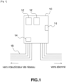
- FIG. 1 is a schematic representation of a housing according to the present invention, in a particular embodiment.
- an optical connection box 10 in accordance with the present invention comprises one or more state sensors 12, which measure at least one physical parameter of the box 10 and/or which detect the opening and closing of the box 10.
- this physical parameter may be the degree of humidity of the casing 10 or the temperature of the casing 10 or the pressure, shocks, vibrations, etc.
- the box 10 further comprises a means 14 of remote identification of the box electronically.
- the remote identification means 14 can be an NFC (near field communication) or RFID (radio frequency identification) tag. .
- This label is for example directly printed on the box 10, or appears on a self-adhesive label affixed for example to the outside of the box 10.
- the remote identification means 14 can be made in the form of a badge and be inside the housing 10.
- the box 10 may also include an intelligent locking device 16, equipped with electronic circuitry allowing it to be controlled remotely via a possibly mobile telecommunications terminal.
- the opening and closing of the box 10 can be conditional on the execution of a user authentication procedure.
- the open or closed state of the box 10 can be stored in a remote register.
- the smart locking device 16 can communicate with the outside, for example via NFC or RFID technology, such as the means 14 for remote identification of the box 10.
- FIG. 1 shows that the box 10 is connected, in a manner known per se, to a fiber optic telecommunications network 18, on the one hand to a node belonging to the core of the network 18 and on the other hand, to subscriber equipment, that is to say to a user equipment of the network 18.
- a system for monitoring the integrity of the network 18 in accordance with the present invention comprises at least one junction box 10 as described above, as well as a platform for supervising interventions in the network 18.
- the supervision platform is adapted to communicate with the box.
- the supervision platform includes a reading means suitable for transmitting and receiving signals in the direction of and coming from the NFC tag of the box 10 and coming from the state sensor(s) 12.
- the supervision platform may comprise an enrollment register of the technicians who carry out the interventions, containing information identifying these technicians.
- the supervision platform can also comprise a means of recording interventions, which stores for example the date, time and duration of interventions, the identification data of the technician who intervened and the information of identification of the case 10 concerned as well as the value of the physical parameters measured by the sensor(s) 12 at the start and at the end of the intervention.
- a means of recording interventions which stores for example the date, time and duration of interventions, the identification data of the technician who intervened and the information of identification of the case 10 concerned as well as the value of the physical parameters measured by the sensor(s) 12 at the start and at the end of the intervention.
- the invention finds application in all types of optical networks, whether FTTH (Fiber to the Home) or FTTE (Fiber to the Home) networks. company, in English “Fiber to the Enterprise") or mobile networks.
- connection boxes It can easily be extended to other elements of a network than connection boxes.
Landscapes
- Physics & Mathematics (AREA)
- General Physics & Mathematics (AREA)
- Optics & Photonics (AREA)
- Engineering & Computer Science (AREA)
- Architecture (AREA)
- Civil Engineering (AREA)
- Structural Engineering (AREA)
- Data Exchanges In Wide-Area Networks (AREA)
- Investigating Or Analysing Materials By Optical Means (AREA)
- Light Guides In General And Applications Therefor (AREA)
Abstract
Description
- La présente invention se rapporte à un boîtier de raccordement optique intelligent.
- L'invention appartient au domaine des réseaux de télécommunications à fibres optiques.
- Les réseaux de télécommunications à fibres optiques comportent notamment des câbles à fibres optiques et des boîtiers de raccordement optiques.
- Les boîtiers de raccordement peuvent être installés à l'extérieur ou dans des bâtiments. Ils assurent la protection des fibres optiques, des épissures et des connexions.
- Lorsqu'ils sont installés à l'extérieur, notamment en chambre de tirage ou sur poteau, les boîtiers de raccordement sont soumis aux aléas climatiques. Des infiltrations d'eau peuvent dégrader partiellement ou totalement les performances du réseau optique.
- A l'intérieur de bâtiments, des infiltrations de poussières ou d'insectes peuvent également dégrader les performances du réseau optique. En outre, de telles dégradations sont imprévisibles et ne sont actuellement pas anticipées.
- Par ailleurs, les boîtiers de raccordement sont installés par des techniciens d'intervention. Lorsque les réseaux sont mutualisés, différents techniciens interviennent respectivement pour le compte de différents opérateurs. A l'installation ou lors d'interventions ultérieures sur le boîtier, il est donc difficile d'identifier précisément le technicien. Lorsqu'elle est possible, cette identification n'est pas immédiate. Or la majeure partie des défaillances apparaissent lors de l'intervention d'un technicien qui doit ouvrir les boîtiers, provoquant ainsi l'entrée d'éléments extérieurs et des déconnexions intempestives des raccordements préétablis.
- En outre, sur les réseaux denses, plusieurs boîtiers peuvent être installés à proximité les uns des autres. Cela rend leur identification délicate, ce qui engendre un risque de ne pas intervenir sur le bon boîtier.
- En effet, théoriquement, chaque boîtier dispose d'une identification physique unique, par exemple au moyen d'une étiquette à frapper ou imprimée, d'un QR code ou d'un marquage à l'encre. Néanmoins, la durée de vie de ce moyen d'identification varie selon sa nature (encre indélébile, étiquette métallique, plastique, adhésive, etc.). Lorsque l'identification n'est plus lisible ou est absente, le technicien n'a pas la certitude d'intervenir sur le bon boîtier et peut se tromper ou perdre un temps significatif en recherches afin de s'assurer d'effectuer les bonnes connexions aux bons endroits.
- Enfin, chaque intervention sur un boîtier engendre potentiellement un stress sur les fibres optiques. De plus, certaines fonctionnalités ou capacités du boîtier peuvent être altérées lors de l'intervention. Etant donné l'absence d'historique des interventions sur ces boîtiers, il est impossible de connaître l'état précis de chaque boîtier afin de pouvoir anticiper les pannes. Sur certains sites, un carnet d'enregistrement est théoriquement renseigné par le technicien à chaque intervention, mais en pratique, il est quasiment inexistant, pas toujours renseigné et n'est pas consultable à distance. Aucune maintenance préventive ne peut être partagée entre opérateurs du réseau et les tests d'état tels que des tests d'étanchéité pour les boîtiers étanches munis d'une valve doivent être réalisés in situ.
- La présente invention a pour but de remédier aux lacunes précitées de l'art antérieur.
- Dans ce but, la présente invention propose un boîtier de raccordement de fibres optiques, remarquable en ce qu'il comporte :
- au moins un capteur d'état mesurant au moins un paramètre physique du boîtier et/ou détectant l'ouverture et la fermeture du boîtier ; et
- un moyen d'identification à distance du boîtier par voie électronique.
- Ainsi, la présente invention permet d'identifier le boîtier de raccordement de façon sûre et pérenne et de connaître l'état du boîtier de façon dynamique sans avoir besoin de se déplacer. Cela permet d'anticiper les pannes et d'éviter toute erreur d'identification du boîtier lors de l'intervention du technicien.
- Dans un mode particulier de réalisation, le boîtier de raccordement comporte en outre un dispositif de verrouillage intelligent.
- Cela permet de garantir en cas d'intervention que seul le technicien habilité ouvre et ferme le boîtier.
- Dans un mode particulier de réalisation, le moyen d'identification à distance est une étiquette NFC ou RFID.
- Une telle étiquette est très facile à installer sur le boîtier et permet une communication fiable et sans contact.
- Dans un mode particulier de réalisation, le capteur d'état mesure le degré d'humidité du boîtier.
- Cela permet de détecter toute infiltration d'eau préjudiciable au fonctionnement du réseau optique.
- Dans un mode particulier de réalisation, le capteur d'état mesure la température du boîtier.
- Cela permet d'anticiper d'éventuelles défaillances dues à des températures sortant des plages de fonctionnement normal du boîtier.
- Dans le même but que celui indiqué plus haut, la présente invention propose également un système de contrôle de l'intégrité d'un réseau de télécommunications à fibres optiques, remarquable en ce qu'il comporte :
- au moins un boîtier de raccordement tel que succinctement décrit ci-dessus;
- une plateforme de supervision d'interventions dans le réseau adaptée à communiquer avec l'au moins un boîtier de raccordement.
- Outre les mêmes avantages et caractéristiques particulières que ceux du boîtier mentionnés ci-dessus, le système de contrôle proposé permet d'identifier les techniciens intervenant sur le ou les boîtiers du réseau et le ou les boîtiers concernés ainsi que la nature de ces interventions. L'organisation d'une maintenance prédictive du réseau est ainsi rendue possible.
- Dans un mode particulier de réalisation du système, la plateforme comporte un moyen d'enregistrement des interventions.
- Cela permet de disposer d'un historique des interventions qui facilite le suivi du fonctionnement du ou des boîtiers du réseau ainsi que la maintenance prédictive de ce dernier.
- D'autres aspects et avantages de l'invention apparaîtront à la lecture de la description détaillée ci-après de modes particuliers de réalisation, donnés à titre d'exemples nullement limitatifs, en référence aux dessins annexés, dans lesquels :
- [
Fig. 1 ] est une représentation schématique d'un boîtier conforme à la présente invention, dans un mode particulier de réalisation. - Comme le montre la
figure 1 , dans un mode particulier de réalisation, un boîtier 10 de raccordement optique conforme à la présente invention comporte un ou plusieurs capteurs d'état 12, qui mesurent au moins un paramètre physique du boîtier 10 et/ou qui détectent l'ouverture et la fermeture du boîtier 10. - A titre d'exemple nullement limitatif, ce paramètre physique peut être le degré d'humidité du boîtier 10 ou la température du boîtier 10 ou la pression, les chocs, les vibrations, etc.
- Le boîtier 10 comporte en outre un moyen 14 d'identification à distance du boîtier par voie électronique.
- A titre d'exemple nullement limitatif, le moyen 14 d'identification à distance peut être une étiquette NFC (communication en champ proche, en anglais « Near Field Communication ») ou RFID (identification par radiofréquences, en anglais « Radio Frequency IDentification »). Cette étiquette est par exemple directement imprimée sur le boîtier 10, ou figure sur une étiquette autocollante apposée par exemple à l'extérieur du boîtier 10. En variante, le moyen 14 d'identification à distance peut être réalisé sous la forme d'un badge et se trouver à l'intérieur du boîtier 10.
- De façon optionnelle, le boîtier 10 peut comporter en outre un dispositif 16 de verrouillage intelligent, équipé d'une circuiterie électronique lui permettant d'être commandé à distance via un terminal de télécommunications éventuellement mobile. L'ouverture et la fermeture du boîtier 10 peuvent être conditionnées à l'exécution d'une procédure d'authentification de l'utilisateur. L'état ouvert ou fermé du boîtier 10 peut être mémorisé dans un registre distant. Le dispositif 16 de verrouillage intelligent peut communiquer avec l'extérieur par exemple via la technologie NFC ou RFID, comme le moyen 14 d'identification à distance du boîtier 10.
- La
figure 1 montre que le boîtier 10 est relié, de façon connue en soi, à un réseau 18 de télécommunications à fibres optiques, d'une part à un nœud appartenant au cœur du réseau 18 et d'autre part, à un équipement d'abonné, c'est-à-dire à un équipement d'usager du réseau 18. - Un système de contrôle de l'intégrité du réseau 18 conforme à la présente invention comporte au moins un boîtier 10 de raccordement tel que décrit ci-dessus, ainsi qu'une plateforme de supervision d'interventions dans le réseau 18.
- La plateforme de supervision est adaptée à communiquer avec le boîtier. Par exemple, si le boîtier 10 comporte un moyen 14 d'identification à distance du boîtier sous la forme d'une étiquette NFC, la plateforme de supervision comporte un moyen de lecture adapté à émettre et recevoir des signaux en direction de et en provenance de l'étiquette NFC du boîtier 10 et en provenance du ou des capteurs d'état 12.
- En outre, la plateforme de supervision peut comporter un registre d'enrôlement des techniciens qui réalisent les interventions, contenant des informations d'identification de ces techniciens.
- De façon optionnelle, la plateforme de supervision peut également comporter un moyen d'enregistrement des interventions, qui mémorise par exemple la date, l'heure et la durée des interventions, les données d'identification du technicien qui est intervenu et les informations d'identification du boîtier 10 concerné ainsi que la valeur des paramètres physiques mesurés par le ou les capteurs 12 en début et en fin d'intervention.
- L'invention trouve à s'appliquer dans tous les types de réseaux optiques, qu'il s'agisse de réseaux FTTH (fibre jusqu'à la maison, en anglais « Fiber To The Home »), FTTE (fibre jusqu'à l'entreprise, en anglais « Fiber to the Enterprise ») ou de réseaux mobiles.
- Elle peut aisément être étendue à d'autres éléments d'un réseau que les boîtiers de raccordement.
Claims (7)
- Boîtier (10) de raccordement de fibres optiques, caractérisé en ce qu'il comporte :au moins un capteur d'état (12) mesurant au moins un paramètre physique dudit boîtier (10) et/ou détectant l'ouverture et la fermeture dudit boîtier(10) ; etun moyen (14) d'identification à distance dudit boîtier (10) par voie électronique.
- Boîtier (10) selon la revendication 1, caractérisé en ce qu'il comporte en outre un dispositif (16) de verrouillage intelligent.
- Boîtier (10) selon la revendication 1 ou 2, caractérisé en ce que ledit moyen (14) d'identification à distance est une étiquette NFC ou RFID.
- Boîtier (10) selon la revendication 1, 2 ou 3, caractérisé en ce que ledit capteur d'état (12) mesure le degré d'humidité dudit boîtier (10).
- Boîtier (10) selon l'une quelconque des revendications précédentes, caractérisé en ce que ledit capteur d'état (12) mesure la température dudit boîtier (10).
- Système de contrôle de l'intégrité d'un réseau (18) de télécommunications à fibres optiques, caractérisé en ce qu'il comporte :au moins un boîtier (10) de raccordement selon l'une quelconque des revendications précédentes ;une plateforme de supervision d'interventions dans ledit réseau (18) adaptée à communiquer avec ledit au moins un boîtier (10) de raccordement.
- Système selon la revendication 6, caractérisé en ce que ladite plateforme comporte un moyen d'enregistrement desdites interventions.
Applications Claiming Priority (1)
| Application Number | Priority Date | Filing Date | Title |
|---|---|---|---|
| FR2110143A FR3127591A1 (fr) | 2021-09-27 | 2021-09-27 | Boîtier de raccordement optique intelligent |
Publications (1)
| Publication Number | Publication Date |
|---|---|
| EP4155795A1 true EP4155795A1 (fr) | 2023-03-29 |
Family
ID=78212341
Family Applications (1)
| Application Number | Title | Priority Date | Filing Date |
|---|---|---|---|
| EP22192804.7A Withdrawn EP4155795A1 (fr) | 2021-09-27 | 2022-08-30 | Boîtier de raccordement optique intelligent |
Country Status (3)
| Country | Link |
|---|---|
| US (1) | US20230131488A1 (fr) |
| EP (1) | EP4155795A1 (fr) |
| FR (1) | FR3127591A1 (fr) |
Citations (4)
| Publication number | Priority date | Publication date | Assignee | Title |
|---|---|---|---|---|
| EP2259116A2 (fr) * | 2004-11-03 | 2010-12-08 | ADC Telecommunications, Inc. | Boitier de connexion pour cables fibres optiques |
| US20110051341A1 (en) * | 2009-08-26 | 2011-03-03 | Matthew Baldassano | Datacommunications/Telecommunications Patching Systems with Integrated Connectivity Module |
| CN106226881A (zh) * | 2016-08-23 | 2016-12-14 | 江苏明强电气有限公司 | 一种多通道的网络光纤快速配线箱 |
| CN107229098A (zh) * | 2016-03-24 | 2017-10-03 | 沈阳永成烽火科技有限公司 | 一种智能光缆交接箱 |
Family Cites Families (7)
| Publication number | Priority date | Publication date | Assignee | Title |
|---|---|---|---|---|
| US7511259B2 (en) * | 2006-04-24 | 2009-03-31 | Northrop Grumman Corporation | Smart integrated distributed light-powered process control system |
| JP2009092460A (ja) * | 2007-10-05 | 2009-04-30 | Nippon Tsushin Denzai Kk | 液体検知センサ及び光配線函 |
| EP2189964A1 (fr) * | 2008-11-21 | 2010-05-26 | The European Community, represented by the European Commission | Dispositif d'obturation |
| US10477721B2 (en) * | 2016-06-29 | 2019-11-12 | Juniper Networks, Inc. | Mechanism to provide physical location information to any network device |
| CN111351633A (zh) * | 2018-12-20 | 2020-06-30 | 中国移动通信集团四川有限公司 | 光纤交接箱的监控装置、方法、系统、设备和介质 |
| CN210605108U (zh) * | 2019-03-19 | 2020-05-22 | 长园共创电力安全技术股份有限公司 | 光交箱用智能锁控制器盒、智能锁控制器及光交箱 |
| KR102188734B1 (ko) * | 2020-05-21 | 2020-12-09 | 주식회사 씨에쓰정보기술 | 광접속함과 광분배함이 일체로 결합된 결합형 스마트 함체 및 보안 시스템 |
-
2021
- 2021-09-27 FR FR2110143A patent/FR3127591A1/fr not_active Withdrawn
-
2022
- 2022-08-30 EP EP22192804.7A patent/EP4155795A1/fr not_active Withdrawn
- 2022-09-21 US US17/949,894 patent/US20230131488A1/en not_active Abandoned
Patent Citations (4)
| Publication number | Priority date | Publication date | Assignee | Title |
|---|---|---|---|---|
| EP2259116A2 (fr) * | 2004-11-03 | 2010-12-08 | ADC Telecommunications, Inc. | Boitier de connexion pour cables fibres optiques |
| US20110051341A1 (en) * | 2009-08-26 | 2011-03-03 | Matthew Baldassano | Datacommunications/Telecommunications Patching Systems with Integrated Connectivity Module |
| CN107229098A (zh) * | 2016-03-24 | 2017-10-03 | 沈阳永成烽火科技有限公司 | 一种智能光缆交接箱 |
| CN106226881A (zh) * | 2016-08-23 | 2016-12-14 | 江苏明强电气有限公司 | 一种多通道的网络光纤快速配线箱 |
Also Published As
| Publication number | Publication date |
|---|---|
| US20230131488A1 (en) | 2023-04-27 |
| FR3127591A1 (fr) | 2023-03-31 |
Similar Documents
| Publication | Publication Date | Title |
|---|---|---|
| EP3147081B1 (fr) | Dispositif de surveillance de la température et du serrage d'une vis | |
| EP3467605B1 (fr) | Procédé de surveillance d'un système de régulation de la température associé à une armoire électrique | |
| EP0650169A1 (fr) | Système de surveillance d'une installation industrielle | |
| US20120219418A1 (en) | Gps automated tracking of mobile monitoring units | |
| EP3118824B1 (fr) | Système pour le suivi des conditions de transport de marchandises | |
| FR3127591A1 (fr) | Boîtier de raccordement optique intelligent | |
| FR2982774A1 (fr) | Dispositif de surveillance de bornes incendie. | |
| EP3379269B1 (fr) | Accessoire de contrôle pour un appareil électrique pourvu d'une borne de raccordement | |
| EP0813068B1 (fr) | Dispositif pour détecter et localiser des anomalies de la protection électromagnétique d'un système | |
| EP3501940B1 (fr) | Véhicule ferroviaire, système ferroviaire et procédé de composition de véhicule ferroviaire associés | |
| WO2009118416A1 (fr) | Procédé et dispositif de délivrance d'une attestation numérique de domicile | |
| CN108332780B (zh) | 光学供电的传感器校准数据存储模块 | |
| FR3070785A1 (fr) | Systeme de surveillance d'un aeronef | |
| EP1191477A1 (fr) | Dispositif électronique intégré sécurisé | |
| EP4156058A1 (fr) | Système de supervision d'un réseau constitué d´une pluralité de dispositifs | |
| WO2020016326A1 (fr) | Capteur omnidirectionnel pour la determination d'une valeur environnementale d'un objet pivotant | |
| FR3099589A1 (fr) | capteur intelligent autonome de mesure de données physiques d’un milieu comportant au moins un géophone | |
| WO2014167080A1 (fr) | Marqueur d'identification | |
| FR3079607A1 (fr) | Procede de surveillance d'au moins une mesure de l'etat structurel d'un edifice | |
| US20250323721A1 (en) | Portable devices for checking coverage of fiber optic links | |
| EP4598047B1 (fr) | Détection d'incendie par un compteur électrique préexistant | |
| FR3134887A1 (fr) | Dispositif pouvant être enterré de mesure et de communication d’une information mesurée au moyen d’un organe de mesure | |
| FR3041460A1 (fr) | Systeme de detection d'intrusion dans un lieu | |
| FR3060929A1 (fr) | Mise en oeuvre conditionnelle d' un service | |
| GB2613167A (en) | A valve sensor for a subterranean water pipe valve operated by a key |
Legal Events
| Date | Code | Title | Description |
|---|---|---|---|
| PUAI | Public reference made under article 153(3) epc to a published international application that has entered the european phase |
Free format text: ORIGINAL CODE: 0009012 |
|
| STAA | Information on the status of an ep patent application or granted ep patent |
Free format text: STATUS: THE APPLICATION HAS BEEN PUBLISHED |
|
| AK | Designated contracting states |
Kind code of ref document: A1 Designated state(s): AL AT BE BG CH CY CZ DE DK EE ES FI FR GB GR HR HU IE IS IT LI LT LU LV MC MK MT NL NO PL PT RO RS SE SI SK SM TR |
|
| STAA | Information on the status of an ep patent application or granted ep patent |
Free format text: STATUS: REQUEST FOR EXAMINATION WAS MADE |
|
| 17P | Request for examination filed |
Effective date: 20230929 |
|
| RBV | Designated contracting states (corrected) |
Designated state(s): AL AT BE BG CH CY CZ DE DK EE ES FI FR GB GR HR HU IE IS IT LI LT LU LV MC MK MT NL NO PL PT RO RS SE SI SK SM TR |
|
| RAP1 | Party data changed (applicant data changed or rights of an application transferred) |
Owner name: AGINODE GROUP |
|
| STAA | Information on the status of an ep patent application or granted ep patent |
Free format text: STATUS: THE APPLICATION HAS BEEN WITHDRAWN |
|
| 18W | Application withdrawn |
Effective date: 20241216 |