EP4155794A1 - Compact light splitting devices and methods - Google Patents
Compact light splitting devices and methods Download PDFInfo
- Publication number
- EP4155794A1 EP4155794A1 EP22192837.7A EP22192837A EP4155794A1 EP 4155794 A1 EP4155794 A1 EP 4155794A1 EP 22192837 A EP22192837 A EP 22192837A EP 4155794 A1 EP4155794 A1 EP 4155794A1
- Authority
- EP
- European Patent Office
- Prior art keywords
- coupler
- light
- leg
- wavelengths
- splitting device
- Prior art date
- Legal status (The legal status is an assumption and is not a legal conclusion. Google has not performed a legal analysis and makes no representation as to the accuracy of the status listed.)
- Pending
Links
- 238000000034 method Methods 0.000 title description 21
- 230000003287 optical effect Effects 0.000 claims abstract description 93
- 230000000295 complement effect Effects 0.000 claims abstract description 22
- 238000009826 distribution Methods 0.000 claims abstract description 19
- 230000008878 coupling Effects 0.000 claims description 36
- 238000010168 coupling process Methods 0.000 claims description 36
- 238000005859 coupling reaction Methods 0.000 claims description 36
- 230000001902 propagating effect Effects 0.000 description 6
- 230000008569 process Effects 0.000 description 5
- 230000003111 delayed effect Effects 0.000 description 4
- 230000004048 modification Effects 0.000 description 4
- 238000012986 modification Methods 0.000 description 4
- 230000010363 phase shift Effects 0.000 description 3
- 230000007423 decrease Effects 0.000 description 2
- 230000001419 dependent effect Effects 0.000 description 2
- 238000013461 design Methods 0.000 description 2
- 238000010586 diagram Methods 0.000 description 2
- 239000000463 material Substances 0.000 description 2
- 238000012544 monitoring process Methods 0.000 description 2
- 239000013307 optical fiber Substances 0.000 description 2
- 238000005191 phase separation Methods 0.000 description 2
- 238000013459 approach Methods 0.000 description 1
- 230000008901 benefit Effects 0.000 description 1
- 230000008859 change Effects 0.000 description 1
- 230000001427 coherent effect Effects 0.000 description 1
- 230000003247 decreasing effect Effects 0.000 description 1
- 230000007717 exclusion Effects 0.000 description 1
- 238000010348 incorporation Methods 0.000 description 1
- 229910021420 polycrystalline silicon Inorganic materials 0.000 description 1
- 229920005591 polysilicon Polymers 0.000 description 1
- 238000000926 separation method Methods 0.000 description 1
Images



Classifications
-
- G—PHYSICS
- G02—OPTICS
- G02B—OPTICAL ELEMENTS, SYSTEMS OR APPARATUS
- G02B6/00—Light guides; Structural details of arrangements comprising light guides and other optical elements, e.g. couplings
- G02B6/24—Coupling light guides
- G02B6/26—Optical coupling means
- G02B6/28—Optical coupling means having data bus means, i.e. plural waveguides interconnected and providing an inherently bidirectional system by mixing and splitting signals
- G02B6/293—Optical coupling means having data bus means, i.e. plural waveguides interconnected and providing an inherently bidirectional system by mixing and splitting signals with wavelength selective means
- G02B6/29379—Optical coupling means having data bus means, i.e. plural waveguides interconnected and providing an inherently bidirectional system by mixing and splitting signals with wavelength selective means characterised by the function or use of the complete device
- G02B6/29391—Power equalisation of different channels, e.g. power flattening
-
- G—PHYSICS
- G02—OPTICS
- G02B—OPTICAL ELEMENTS, SYSTEMS OR APPARATUS
- G02B6/00—Light guides; Structural details of arrangements comprising light guides and other optical elements, e.g. couplings
- G02B6/24—Coupling light guides
- G02B6/26—Optical coupling means
- G02B6/28—Optical coupling means having data bus means, i.e. plural waveguides interconnected and providing an inherently bidirectional system by mixing and splitting signals
-
- G—PHYSICS
- G02—OPTICS
- G02B—OPTICAL ELEMENTS, SYSTEMS OR APPARATUS
- G02B6/00—Light guides; Structural details of arrangements comprising light guides and other optical elements, e.g. couplings
- G02B6/24—Coupling light guides
- G02B6/26—Optical coupling means
- G02B6/28—Optical coupling means having data bus means, i.e. plural waveguides interconnected and providing an inherently bidirectional system by mixing and splitting signals
- G02B6/293—Optical coupling means having data bus means, i.e. plural waveguides interconnected and providing an inherently bidirectional system by mixing and splitting signals with wavelength selective means
- G02B6/29346—Optical coupling means having data bus means, i.e. plural waveguides interconnected and providing an inherently bidirectional system by mixing and splitting signals with wavelength selective means operating by wave or beam interference
- G02B6/2935—Mach-Zehnder configuration, i.e. comprising separate splitting and combining means
-
- G—PHYSICS
- G02—OPTICS
- G02B—OPTICAL ELEMENTS, SYSTEMS OR APPARATUS
- G02B6/00—Light guides; Structural details of arrangements comprising light guides and other optical elements, e.g. couplings
- G02B6/10—Light guides; Structural details of arrangements comprising light guides and other optical elements, e.g. couplings of the optical waveguide type
- G02B6/12—Light guides; Structural details of arrangements comprising light guides and other optical elements, e.g. couplings of the optical waveguide type of the integrated circuit kind
- G02B2006/12133—Functions
- G02B2006/1215—Splitter
-
- G—PHYSICS
- G02—OPTICS
- G02B—OPTICAL ELEMENTS, SYSTEMS OR APPARATUS
- G02B6/00—Light guides; Structural details of arrangements comprising light guides and other optical elements, e.g. couplings
- G02B6/10—Light guides; Structural details of arrangements comprising light guides and other optical elements, e.g. couplings of the optical waveguide type
- G02B6/12—Light guides; Structural details of arrangements comprising light guides and other optical elements, e.g. couplings of the optical waveguide type of the integrated circuit kind
- G02B2006/12133—Functions
- G02B2006/12154—Power divider
Definitions
- This disclosure relates generally to light splitting devices. More particularly, embodiments herein relate to an optical system with light couplers that are optically coupled to one another with a phase delay positioned between the light couplers.
- optical systems employ multiple light inputs to measure various types of information. Some of these optical systems may output light at multiple different wavelengths. However, as the number of monitored wavelengths increase, the size, cost, and complexity of the optical system increase as well. Due to the scaling of the size of the optical system with the number of light inputs, light sources and/or wavelengths of light, the optical systems used for generating, splitting, coupling, and/or monitoring light may not be suitable for certain applications due to factors such as size, cost, and complexity. As one example, such optical systems may take up too much space to be reasonably incorporated into compact electronic devices, such as mobile phones, tablet computing devices, laptops, wearables, and the like.
- existing optical systems for emitting and/or monitoring light may function over a narrow wavelength range and may not efficiently function in different or broad wavelength ranges. Accordingly, it may be desirable to employ a system that performs across a broadband wavelength range while maintaining a compact form factor for incorporation in compact electronic devices.
- Embodiments of the systems, devices, methods, and apparatuses described in the present disclosure are directed to a compact broadband light splitting device. Also described are systems, devices, methods, and apparatuses directed to a light splitting device that employs cascaded two-by-two directional couplers or cascaded two-by-two tapered couplers.
- the cascaded two-by-two directional couplers individually may be narrowband two-by-two couplers.
- the directional splitting device may perform over a broader bandwidth (e.g., broadband wavelengths).
- the two-by-two tapered couplers individually may be narrowband two-by-two couplers, but when optically coupled to one another with a phase delay positioned between the two-by-two tapered couplers, the tapered splitting device may function over a broader bandwidth (e.g., broadband wavelengths).
- the present disclosure describes a light splitting device.
- the light splitting device may include a first coupler that couples light over an operating bandwidth of wavelengths.
- the first coupler may include a first leg of the first coupler and a second leg of the first coupler, optically coupled to the first leg of the first coupler.
- the light splitting device may also include a second coupler that couples light over the operating bandwidth of wavelengths.
- the second coupler may include a first leg of the second coupler and a second leg of the second coupler optically coupled to the first leg of the second coupler.
- the light splitting device may also include a phase delay positioned between the first coupler and the second coupler. Additionally, the first coupler has a first splitting power relationship, the second coupler has a second splitting power relationship, and the first coupler and the second coupler have complementary splitting power relationships over the operating bandwidth of wavelengths
- the present disclosure may include a light splitting device.
- the light splitting device may include a first coupler for coupling light with a first splitting power relationship between wavelengths of light and output optical power, where the first coupler includes a first leg and a second leg of the first coupler positioned so that the light couples between the second leg and the first leg.
- the light splitting device may include a second coupler for coupling light with a second splitting power relationship between wavelengths of light and output optical power, the second coupler including a first leg and a second leg of the second coupler positioned so that the light couples between the first leg of the second coupler and the second leg of the second coupler; and a phase delay positioned between the second leg of the first coupler and second leg of the second coupler, where the first and second splitting power relationships between the wavelengths of light and the output optical power are different from one another.
- the present disclosure may include a method for splitting light.
- the method may include inputting a first input light to a first coupler, outputting a first and a second output light from the first coupler, delaying a phase of the second output light, receiving the first output light and the phase delayed second output light by a second coupler, and outputting a first and a second output light from the second coupler.
- the first input light and the second input light inputted to the first coupler are within an operating bandwidth of wavelengths
- the first coupler has a first splitting power relationship
- the second coupler has a second splitting power relationship
- the first and second splitting power relationships are complementary across the operating bandwidth of wavelengths.
- cross-hatching or shading in the accompanying figures is generally provided to clarify the boundaries between adjacent elements and also to facilitate legibility of the figures. Accordingly, neither the presence nor the absence of cross-hatching or shading conveys or indicates any preference or requirement for particular materials, material properties, element proportions, element dimensions, commonalities of similarly illustrated elements, or any other characteristic, attribute, or property for any element illustrated in the accompanying figures.
- the term “abutting” means that two elements share a common boundary or otherwise contact one another, while the term “adjacent” means that two elements are near one another and may (or may not) contact one another. Thus, elements that are abutting are also adjacent, although the reverse is not necessarily true. Additionally, two elements that are "optically coupled" to one another may allow light to pass and/or couple from one element to the other element.
- a reference number without an alpha character following the reference number can refer to one or more of the corresponding references, the group of all references, or some of the references.
- "215" can refer to a first coupler leg 215a (e.g., first coupler leg 215a of the first coupler 215, second coupler leg 215b of the first coupler, etc.), can refer to all sections of the first coupler 215, or can refer to one or more legs of the first coupler 215 (e.g., both legs 215a and section 215b of the first coupler 215) depending on the context in which it is used.
- optical systems may employ multiple light inputs, where the light may be split and/or combined.
- Various systems may be used to split and/or combine light emitted by light inputs, but may include different components and may vary from one another in different ways, such as size, optical efficiency, cost, energy efficiency, wavelength dependence or independence, any combination thereof, and so forth.
- light may be split using multiple stages in an optical system and the optical system size may increase with the number of light splitting stages. Because the light splitting devices typically scale with the number of output ports, these devices may become unreasonably large and may not be easily incorporated into the optical system.
- the light splitting device may split and/or combine light using a pair of two-by-two couplers that have complementary optical splitting power relationships.
- the light splitting device may include a first two-by-two coupler, a second two-by-two coupler that are connected in series with a phase delay between the first and second two-by-two couplers.
- the two-by-two couplers are directional couplers.
- the two-by-two couplers are tapered couplers.
- the light splitting devices described herein represent a compact option and may have a wider operating bandwidth than those of the underlying individual two-by-two couplers.
- the "operating bandwidth" for a light splitting component refers to the range of wavelengths over which light, when introduced to an input of the light splitting component, will be split between the outputs of the light splitting component in amounts that meet one or more predetermined criteria.
- the predetermined criteria may be a range of acceptable light splitting ratios.
- the acceptable range of light-splitting ratios may be ratios less than or equal to 1.2:1.
- a first wavelength that is split evenly by the light splitting component e.g., at a 1:1 ratio
- a second wavelength that is split 60/40 between the outputs e.g., at 1.5:1 ratio
- the operating bandwidth for each component is calculated according to the same one or more criteria.
- actual values of the one or more predetermined criteria may vary depending on the overall system needs.
- the light splitting device may have tight tolerances (e.g., less than plus or minus one percent variation from the specifications) or more relaxed tolerances (e.g., less than plus or minus 10 percent variation from the specifications). Regardless of the selection of these values, the light splitting devices described herein may provide an operating bandwidth that is wider than the individual operating bandwidths of its first and second individual two-by-two couplers.
- An individual two-by-two coupler may have an operating bandwidth as discussed above.
- the two-by-two coupler may still receive and split light at wavelengths outside of operating bandwidth, but the light will at these wavelengths be split at different splitting ratios when compared to wavelengths in the operating bandwidth.
- the phase delay as well as the splitting ratio for that wavelength in the other two-by-two coupler may cause the overall splitting of that wavelength of light (i.e., the splitting achieved by the overall light splitting device) to fall within the range of acceptable light splitting ratios.
- a particular wavelength may fall into the operating bandwidth for the light splitting device even though it doesn't fall within the operating bandwidths for one or both of the two-by-two couplers.
- FIG. 1 is a block diagram of an example light splitting device 100 that includes light inputs 105a, 105b, a first coupler 115, a phase delay 125, and a second coupler 130.
- the light inputs 105a, 105b may receive light from one or more light sources (not illustrated in FIG. 1 ).
- the light splitting device 100 may generally efficiently couple light across a wider operating bandwidth even though the first coupler 115 and the second coupler 130 are designed to efficiently couple light over relatively narrow operating bandwidths.
- the operating bandwidth may span at least one micron, although it should be appreciated that the operating bandwidth may span a smaller range (e.g., such as 50 nanometers, 100 nanometers, 400 nanometers, or the like). In these examples, it is possible for an operating bandwidth of the light splitting device 100 that spans one micron may be accomplished even though the first and second couplers 115, 130 each have an operating bandwidth that is narrower than one micron.
- the light inputs 105a, 105b emit input light along light paths 110a, 110b to the first coupler 115.
- the light inputs 105a, 105b may emit light along light paths 110a, 110b that is received by the first coupler 115.
- the light inputs 105a, 105b may receive light from any type of suitable light source including any coherent or semi-coherent light source, or any combination thereof.
- the light sources may emit a single wavelength of light or may be configured as a tunable light source that may emit across a range of wavelengths of light, for example 15 nanometers although other tunable light sources may have different ranges that may be greater than or less than 15 nanometers. Additionally, any number of light sources may be employed in the light splitting device 100.
- the light inputs 105a, 105b may be implemented via waveguides of a photonics integrated circuit, however, the light splitting device may be integrated into a larger optical system that may also employ optical fibers, free space optics, and so forth, to route light at different points within the larger optical system.
- the light paths 110a, 110b may represent waveguides, optical fibers, free space optics, or other elements or media through which light travels.
- the light paths 110a, 110b are waveguides though alternatives to waveguides (e.g., light propagating through a medium such as air or polysilicon between devices) may be used in the larger optical system for coupling light into the first coupler 115.
- the first light input 105a may emit a first wavelength of light on light path 110a and the second light input 105b may emit a second wavelength of light on light path 110b.
- the first coupler and the second coupler are two-by-two couplers.
- the first input of the first coupler 115 may receive a first input of light along light path 110a and the second input of the first coupler 115 may receive a second input of light along light path 110b, thus the first coupler 115 will function to split light received by a single input (e.g., light received from either input).
- the first coupler 115 may be described as receiving a first and second input of light, in other embodiments, the first coupler 115 may receive light on only the first input or only the second input. In the example of receiving a single input of light, the first coupler 115 may be a one-by-two coupler.
- the first coupler 115 may combine and split the light on the first output via the light path 120a and on the second output via the light path 120b of the first coupler 115. Splitting the output light between the first and second outputs may be wavelength dependent. For example, the optical power of the output light may be split evenly when the wavelengths emitted by the light inputs 105a, 105b are within the intended operating bandwidth of the first coupler 115. For a particular wavelength, the optical power of the first output light may split 90 percent of the optical power on the first output and ten percent of the optical power on the second output for some wavelengths that are shorter than the intended operating bandwidth of the first coupler 115.
- the optical power of the output light may split 10 percent of the optical power on the first output and 90 percent of the optical power on the second output for some wavelengths that are longer than the intended operating bandwidth of the first coupler 115.
- this specific example describes the functionality of the outputs for a couple of particular wavelengths, generally for shorter and longer wavelengths outside the intended operating bandwidth the outputs of the individual first and second couplers 115, 130 may output largely asymmetrical optical power. Additionally, there are crossover wavelengths for which the first coupler 115 and the second coupler 130 may evenly split optical power between the outputs.
- the phase delay 125 may be positioned between the first coupler 115 and the second coupler 130. Although the phase delay 125 is illustrated in FIG. 1 is introduced on the light path 120b, this is for discussion purposes only and the phase delay may be introduced (e.g., positioned) on either of the light paths 120a or 120b.
- the phase delay 125 may phase shift the light received from the first coupler 115 and passed to the second coupler 130.
- the phase delay 125 may reduce or eliminate any phase delay between the output light from the first and second outputs of the first coupler 115. In some examples, the phase delay may be one micron or less between the output light from the first and second outputs of the first coupler 115.
- the phase delay 125 may ensure that the outputs may have the same or similar optical power across the operating bandwidth of wavelengths of the light splitting device 100. That is, the delay introduced by the phase delay 125 may result in a more even distribution of optical power across the operating bandwidth of wavelengths of the light splitting device 100. Although the distribution may still have variations across wavelengths, the phase delay 125 may reduce these variations. To achieve this delay, the phase delay 125 may be a variable phase delay, a fixed phase delay, or any suitable phase delay that reduces the variation in the power distribution across the operating bandwidth of wavelengths.
- the light on the light path 120a may pass to the first input of the second coupler 130, the phase delay 125 may pass light to the second input of the second coupler 130, and the second coupler 130 may pass the output light via light paths 135a, 135b.
- the second coupler 130 may be a two-by-two coupler.
- the second splitting power relationship of the second coupler 130 may be complementary to the first splitting power relationship of the first coupler 115, as the inversely proportional splitting power relationships of the first coupler 115 and the second coupler 130 may have an inversely proportional wavelength/optical power relationship (e.g., splitting power relationship) to one another.
- the term "complementary" will be described in further detail herein with reference to FIGs. 2A, 2B , and 2C .
- the second coupler 130 may output light with an optical power that is evenly distributed (e.g., similar or the same optical power on both the outputs of the second coupler 130) within the intended operating bandwidth of the second coupler 130.
- the optical power of the second coupler 130 may split 10 percent of the optical power on the first output of the second coupler and 90 percent of the power optical on the second output of the second coupler 130 for some wavelengths that are shorter than the intended operating bandwidth of the second coupler 130.
- the second coupler 130 may unevenly distribute the light in the opposite direction from the first coupler 115 (e.g., the first coupler 115 outputs optical power with 90 percent on the first output and the second coupler 130 outputs optical power with ten percent on the third output for the same or similar wavelengths that are shorter than the intended operating bandwidths of the first and second couplers 115, 130). Additionally, the optical power of the output light may split 90 percent of the optical power on the first output and ten percent of the optical power on the second output for some wavelengths that are longer than the intended operating bandwidth of the second coupler 130.
- the values of the power splitting ratios described immediately above are used for explanatory purposes only.
- FIG. 2A is an example of a first coupler 215 with example optical power distributions on the outputs and FIG. 2B is an example of a second coupler 230 with example optical power distributions that are complementary to the first coupler of FIG. 2A .
- the first and second couplers described with reference to FIGs. 2A and 2B each have a inversely proportional splitting power relationship between the input wavelength and the optical power splitting ratio between the outputs that may be said to be complementary.
- the term complementary will be described in further detail with reference to FIGs. 2C-2E .
- the first and second couplers that provide this flattened wavelength dependence may be said to be "complementary" as the first coupler may have a splitting power relationship with a positive slope for output optical power and the second coupler may have a splitting power relationship with a negative slope for output optical power (or vice versa).
- the splitting power relationship of the wavelength/optical power splitting ratio for the first and second couplers of FIGs. 2A and 2B may have approximately inversely proportional splitting power relationships over the wavelength operating bandwidth of interest for the light splitting device (e.g., the first splitting power relationship has a positive slope as a function of wavelength and the second splitting power relationship has a negative slope as a function of wavelength).
- the first and second couplers of FIGs. 2A and 2B are examples of the first and second couplers of FIG. 1 and may function as part of the light splitting device 100.
- the function of the first coupler 215 may exhibit a splitting power relationship between the input wavelength and the optical power splitting ratio of the outputs.
- the second coupler 230 (described in FIG.
- the second coupler 230 may also exhibit a splitting power relationship between the input wavelength and the optical power splitting ratio of the outputs, but the second coupler 230 may have a complementary splitting power relationship to the first coupler 215 (e.g., the splitting power relationship of the second coupler 230 may have an approximately inverse relationship to the splitting power relationship of the first coupler 215) as will be described herein with reference to FIGs. 2A-2E .
- the first and second couplers (e.g., together in the light splitting device) generally may exhibit complementary optical power splitting ratios as will be described herein with reference to FIGs. 2C-2E .
- the first coupler 215 may receive a wavelength ⁇ 1 of light at one or both of the first and second inputs 245a, 245b. Because the wavelength ⁇ 1 is outside the operating bandwidth of the first coupler 215, the optical power distribution may be unevenly split at the outputs. As an example, the first output 250a of the first coupler 215 may output 90% of the optical power and the second output 250b of the first coupler may output ten percent of the optical power (or split according to another ratio outside of the desired splitting ratio). The first and second outputs 250a, 250b may be received by the second coupler 230. It should be understood that the phase delay has been omitted from the discussion of FIGs.
- the second coupler 230 receives 90% of optical power on the third input 255a, and 10% of the optical power on the fourth input 255b. Because the second coupler 230 is complementary to the first coupler 215, the optical power at the third output 260a and the fourth output 260b may be closer to an even optical power distribution between the third and fourth outputs 260a, 260b.
- the third output 260a of FIG. 2B will provide further detailed explanation of the wavelength/optical power splitting ratio for complementary outputs.
- FIG. 2C is a graph showing example output signals from an output of the first coupler of an example light splitting device.
- the graph 200 of FIG. 2C illustrates an example curve 240 of the splitting power relationship between the output optical power (e.g., y-axis) as a function of wavelength (e.g., x-axis).
- the curve 240 generally has a "positive" slope, such that the optical power outputted by one of the outputs of the first coupler increases as the input wavelength increases.
- the splitting power relationship between wavelength and the optical power may be approximately linear.
- the output signals from one of the outputs of the first coupler may be transmitted to one of the inputs of the second coupler input.
- the first coupler and the second coupler each have two inputs and two outputs as described with reference to FIGs. 3 and 4 .
- the wavelength (e.g., x-axis) and the power (e.g., y-axis) have arbitrary units as the graph 200 and the curve 240 are used for explanatory purposes only and illustrate an approximate representation of the splitting power relationship between the output optical power as a function of wavelength from one leg of a first coupler.
- FIG. 2D is a graph showing example output signals from an output of the second coupler of an example light splitting device.
- the graph 201 of FIG. 2D illustrates an example curve 245 of the relationship between the output optical power (e.g., y-axis) as a function of wavelength (e.g., x-axis).
- the curve 245 generally has a "negative" slope, such that the optical power outputted by one of the outputs of the second coupler decreases as the input wavelength increases.
- FIG. 2E is a graph showing example output signals from an output of the light splitting device using the first and second couplers described with reference to FIGS. 2A - 2D .
- the graph 202 of FIG. 2E illustrates an example curve 250 of the relationship between the output optical power (e.g., y-axis) as a function of wavelength (e.g., x-axis) exhibited by the output of the light splitting device.
- the curve 250 generally has a "flat" slope, such that the optical power outputted by one of the outputs of the light splitting device remains flatter across the operating bandwidth of wavelengths. Put another way, the optical power output is approximately the same across the operating bandwidth of wavelengths, thus decreasing the wavelength dependence of the light splitting device.
- FIG. 3 is an example directional light splitting device with directional couplers.
- the directional light splitting device 300 includes a first directional coupler 315, a phase delay 325, and a second directional coupler 330.
- the first directional coupler 315 includes a first leg 315a and a second leg 315b.
- the second directional coupler 330 includes a third leg 330a and a fourth leg 330b with outputs 335a, 335b, respectively.
- the light splitting device 300 may function over a wider operating bandwidth of wavelengths (e.g., broadband wavelengths) than each of the individual first and second directional couplers 315, 330.
- the directional light splitting device 300 may be a compact device capable of efficiently functioning over a defined operating bandwidth (in some instances spanning a micron or more) while maintaining a small form factor (e.g., approximately less than 2.5 mm).
- first and second directional couplers 315, 330 may be selected because the first directional coupler 315 is complementary to the second directional coupler 330.
- first directional coupler 315 may have a splitting power relationship with a positive slope for output optical power and the second directional coupler 330 may have a splitting power relationship with a negative slope for output optical power. It may be understood that the either one of the directional couplers may have a positive slope as long as the other directional coupler has a wavelength relationship with a negative slope for output optical power.
- the light splitting device 300 may function over a wider operating bandwidth than either of the individual first or second directional couplers 315, 330. It is the approximately inverse splitting power relationship of the first and second directional couplers 315, 330 that allow the light splitting device 300 to function over the wider operating bandwidth while maintaining a compact form factor. That is, each of the first and second directional couplers 315, 330 may individually be designed to efficiently couple light over a first operating bandwidth, but when optically coupled together in a light splitting device 300 efficiently function over a wider wavelength operating bandwidth.
- the first directional coupler 315 has a first leg 315a and a second leg 315b.
- the first leg 315a has a first input 310a and the second leg 315b has a second input 310b.
- the first and second inputs 310a, 310b may receive light directly from light sources or via light paths (e.g., waveguides or any suitable light transmitting medium).
- the received light at a given time may be one or more wavelengths, but generally may be over a broadband operating bandwidth of wavelengths.
- first and second legs 315a, 315b of the first directional coupler 315 are depicted as consistent widths, but the widths of the first and second legs 315a, 315b may vary so long as the functionality and form factor of the first directional coupler 315 remain similar or the same.
- first leg 315a and the second leg 315b may be spaced far enough apart from one another that light coupling between the first and second legs 315a, 315b may not occur.
- the first and second legs 315a, 315b may curve so that in a central location (e.g., first coupling area), the light propagating through the first leg 315a may optically couple to the second leg 315b and/or vice versa.
- first coupling area Through the first coupling area, the first and second legs 315a, 315b may be separated from one another by a gap.
- the gap is depicted as a constant width in FIG.
- the width may widen or grow narrower as the light propagates through the first and second legs 315a, 315b in other embodiments, so long as the coupling between the first and second legs 315a, 315b is the same or similar as when the gap is a constant width.
- the light may continue to propagate through the device as the first and second legs 315a, 315b separate from one another. As the first and second legs 315a, 315b are separated by a larger gap, the coupling between the first and second legs 315a, 315b may decrease. At the outputs of the first directional coupler 315, the first and second legs 315a, 315b are not optically coupled to one another. The coupled light may then be output by the first directional coupler 315. As shown in FIG. 3 , the light output from the second leg 315b may be passed to the phase delay 325.
- the light splitting device 300 also includes a phase delay 325.
- the phase delay 325 may be positioned on one of the first or second legs of the first and second directional couplers 315, 330. As shown, the phase delay 325 is positioned between the first and second directional couplers 315, 330 and on the second leg 315b of the first directional coupler 315 and the second leg 320b of the second directional coupler 330, but the phase delay 325 may be positioned on the first leg as well. Generally, the phase delay 325 is positioned within the light splitting device 300 so that the leg on which it is positioned is not optically coupled to the other leg of the same directional coupler of the light splitting device 300.
- the phase delay 325 may shift the phase of light and may be at least partially dependent on the complementary splitting power relationship of the first and second directional couplers 315, 330.
- the phase shift of the light that passes through the phase delay 325 may assist in generating an even distribution of optical power from the second directional coupler 330 over the operating bandwidth of interest. That is, the phase delay 325 functions to remove the variation of the optical power distribution over the operating bandwidth of broadband wavelengths. Because the phases of the light propagating through the directional light splitting device 300 affect the amplitude of the light propagating through the directional light splitting device 300, the phase shift also affects the optical power output distribution.
- the propagating light may be represented as a generally sinusoidal wave and the light couples between the respective legs of the first and second directional couplers 315, 330 as it passes through the light splitting device 300.
- the light may pass from the phase delay 325 and to a third leg 330a of the second directional coupler 330.
- the second directional coupler 330 may be complementary to the first directional coupler 315 and similarly may have two legs, third and fourth legs 330a and 330b.
- the third leg 330a may receive the light from the first leg 315a directly as the first and second directional couplers 315, 330 may be abutted such that the light may propagate directly from the first leg 315a of the first directional coupler to the third leg 330a.
- first and second directional couplers 315, 330 may be adjacent to one another or may be separated from one another by a suitable light coupling medium, so long as the light may efficiently pass from the first directional coupler 315 to the second directional coupler 330 with low optical loss (e.g., less than five percent loss).
- the light may propagate through the second directional coupler 330 and may be output at the third output 335a and fourth output 335b.
- the output light from each of the third and fourth outputs 335a, 335b may have an even distribution over a broadband wavelength operating bandwidth.
- the distribution between the third and fourth outputs 335a, 335b of the second directional coupler 330 may be said to be "even” if it's within a specified tolerance (e.g., the two optical power outputs are within 20 percent of one another).
- the optical power distribution may be 40 percent on the third arm 335a and 60 percent on the fourth arm 335b of the second directional coupler.
- FIG. 4 is an example tapered light splitting device with tapered couplers.
- the tapered light splitting device 400 includes a first tapered coupler 415, a phase delay 425, and a second tapered coupler 430.
- the first tapered coupler 415 includes a first leg 415a and a second leg 415b and the second tapered coupler 430 includes a third leg 430a and a fourth leg 430b.
- the light splitting device 400 may function over a wider operating bandwidth of wavelengths (e.g., broadband wavelengths) than each of the individual first and second tapered couplers 415, 430. Due to the similarity of the directional light splitting device 300 of FIG. 3 and the tapered light splitting device 400 of FIG. 4 , only the primary difference will be described with reference to FIG. 4 .
- the tapered coupler 415 includes the first leg 415a and the second leg 415b.
- the first and second legs 415a, 415b may be spaced apart from one another at the first and second inputs 410a, 410b, and move closer to one another as the first and second legs 415a, 415b approach the first coupling region.
- the first and second legs 415a, 415b may have consistent widths where the legs are straight and may become narrower as the first and second legs 415a, 415b become closer to one another.
- first and second legs 415a, 415b may have varied widths so long as the light may similarly propagate through the first and second legs 415a, 415b without causing any appreciable optical differences in the propagating light (e.g., the light doesn't generate any undesirable modes, no undesirable optical loss, and so forth).
- the first and second legs 415a, 415b may taper in the first coupling area (e.g., where the first and second legs 415a, 415b are optically coupled to one another).
- the first and second legs 415a, 415b may change in width as light propagates through the first coupling area.
- the first leg 415a may be narrower and may taper to a wider width and the second leg 415b may be wider than the first leg 415a at the start of the coupling area and then become narrower. It may be understood that either of the first and second legs 415a, 415b may start wide or narrow as long as the adiabatic taper is maintained throughout the first coupling area.
- first leg 415a and the second leg 415b may be inversely tapered in the coupling area.
- first coupling area of the first tapered coupler 415 light may couple from the first leg 415a, to the second leg 415b, and vice versa. Because the first and second legs 415a, 415b are slowly tapered, the light may adiabatically couple between the first and second legs 415a, 415b.
- the tapering of the first and second tapered couplers 415, 430 may be used for output optical power equalization, but may depend on the tradeoff with the phase separation between the respective legs of the first and second couplers 415, 430. Additionally, The taper lengths of the tapers in the first and second coupling areas of the first and second tapered couplers 415, 430, respectively, may achieve the phase separation and the power equalization between the first and second couplers 415, 430 over the operating bandwidth with the assistance of the phase delay 425.
- first and second couplers 415, 430 in the first and second coupling areas may be a primary design consideration; however, the first and second coupler widths are accounted for to provide the desired light coupling between the respective legs of the first and second couplers 415, 430.
- tapered waveguides may be used for adiabatically coupling light between waveguides, it is understood that the longer and slower the taper of the waveguide, the better the performance of the device.
- first and second tapered couplers 415, 430 that are complementary to one another, the inverse functionality over wavelength allows the tapered light splitting device 400 to maintain an overall compact form function (e.g., less than two millimeters) while efficiently functioning over a broadband operating wavelength range.
- any sequence or order of steps that can be described in the disclosure does not, in and of itself, indicate a requirement that the steps be performed in that order. Further, some steps may be performed simultaneously despite being described or implied as occurring non-simultaneously (e.g., because one step is described after the other step).
- the illustration of a process by its description in a drawing does not imply that the illustrated process is exclusive of other variations and modification thereto, does not imply that the illustrated process or any of its steps are necessary to one or more of the examples, and does not imply that the illustrated process is preferred.
Landscapes
- Physics & Mathematics (AREA)
- General Physics & Mathematics (AREA)
- Optics & Photonics (AREA)
- Optical Integrated Circuits (AREA)
Abstract
Configurations for a light splitting device (300) used for light splitting over an operating bandwidth of wavelengths are disclosed. The light splitting device (300) may include a first coupler (315) and a second coupler (330), where the first coupler (315) has a first splitting power relationship and the second coupler (330) has a second splitting power relationship and the first and second splitting power relationships are complementary to one another over the operating bandwidth of wavelengths. The light splitting device (300) may further include a phase delay (325) positioned between the first and second couplers (314, 330). The phase delay (325) may result in the output light having an approximately even optical power distribution across the operating bandwidth of wavelengths. In some embodiments, the first and second couplers (315, 330) may be directional couplers and, in other embodiments, the first and second couplers (315, 330) may be tapered couplers.
Description
- This application claims the benefit under 35 U.S. C. § 119(e) of
U.S. Provisional Patent Application No. 63/248,236, filed September 24, 2021 - This disclosure relates generally to light splitting devices. More particularly, embodiments herein relate to an optical system with light couplers that are optically coupled to one another with a phase delay positioned between the light couplers.
- Generally, optical systems employ multiple light inputs to measure various types of information. Some of these optical systems may output light at multiple different wavelengths. However, as the number of monitored wavelengths increase, the size, cost, and complexity of the optical system increase as well. Due to the scaling of the size of the optical system with the number of light inputs, light sources and/or wavelengths of light, the optical systems used for generating, splitting, coupling, and/or monitoring light may not be suitable for certain applications due to factors such as size, cost, and complexity. As one example, such optical systems may take up too much space to be reasonably incorporated into compact electronic devices, such as mobile phones, tablet computing devices, laptops, wearables, and the like. Additionally, existing optical systems for emitting and/or monitoring light may function over a narrow wavelength range and may not efficiently function in different or broad wavelength ranges. Accordingly, it may be desirable to employ a system that performs across a broadband wavelength range while maintaining a compact form factor for incorporation in compact electronic devices.
- Embodiments of the systems, devices, methods, and apparatuses described in the present disclosure are directed to a compact broadband light splitting device. Also described are systems, devices, methods, and apparatuses directed to a light splitting device that employs cascaded two-by-two directional couplers or cascaded two-by-two tapered couplers. The cascaded two-by-two directional couplers individually may be narrowband two-by-two couplers. When the two-by-two directional couplers are optically coupled to one another with a phase delay positioned on one of the arms between the two-by-two directional couplers, the directional splitting device may perform over a broader bandwidth (e.g., broadband wavelengths). Similarly, the two-by-two tapered couplers individually may be narrowband two-by-two couplers, but when optically coupled to one another with a phase delay positioned between the two-by-two tapered couplers, the tapered splitting device may function over a broader bandwidth (e.g., broadband wavelengths).
- In some examples, the present disclosure describes a light splitting device. The light splitting device may include a first coupler that couples light over an operating bandwidth of wavelengths. The first coupler may include a first leg of the first coupler and a second leg of the first coupler, optically coupled to the first leg of the first coupler. The light splitting device may also include a second coupler that couples light over the operating bandwidth of wavelengths. The second coupler may include a first leg of the second coupler and a second leg of the second coupler optically coupled to the first leg of the second coupler. The light splitting device may also include a phase delay positioned between the first coupler and the second coupler. Additionally, the first coupler has a first splitting power relationship, the second coupler has a second splitting power relationship, and the first coupler and the second coupler have complementary splitting power relationships over the operating bandwidth of wavelengths
- In other examples, the present disclosure may include a light splitting device. The light splitting device may include a first coupler for coupling light with a first splitting power relationship between wavelengths of light and output optical power, where the first coupler includes a first leg and a second leg of the first coupler positioned so that the light couples between the second leg and the first leg. The light splitting device may include a second coupler for coupling light with a second splitting power relationship between wavelengths of light and output optical power, the second coupler including a first leg and a second leg of the second coupler positioned so that the light couples between the first leg of the second coupler and the second leg of the second coupler; and a phase delay positioned between the second leg of the first coupler and second leg of the second coupler, where the first and second splitting power relationships between the wavelengths of light and the output optical power are different from one another.
- In other examples, the present disclosure may include a method for splitting light. The method may include inputting a first input light to a first coupler, outputting a first and a second output light from the first coupler, delaying a phase of the second output light, receiving the first output light and the phase delayed second output light by a second coupler, and outputting a first and a second output light from the second coupler. The first input light and the second input light inputted to the first coupler are within an operating bandwidth of wavelengths, the first coupler has a first splitting power relationship, the second coupler has a second splitting power relationship, and the first and second splitting power relationships are complementary across the operating bandwidth of wavelengths.
- In addition to the example aspects and embodiments described above, further aspects and embodiments will become apparent by reference to the drawings and by study of the following description.
-
-
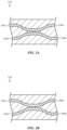
FIG. 1 is a block diagram of an example light splitting device. -
FIG. 2A is an example of a first coupler with example optical power distributions on the outputs. -
FIG. 2B is an example of a second coupler with example optical power distributions that are complementary to the first coupler ofFIG. 2A . -
FIG. 2C is a graph showing example output signals from a first two-by-two coupler of an example light splitting device. -
FIG. 2D is a graph showing example output signals from a second two-by-two coupler of an example light splitting device. -
FIG. 2E is a graph showing example output signals from the light splitting device using the first and second two-by-two couplers ofFIGS. 2A and 2B -
FIG. 3 is an example directional light splitting device with cascaded directional two-by-two couplers. -
FIG. 4 is an example tapered light splitting device with cascaded tapered two-by-two couplers. - The use of cross-hatching or shading in the accompanying figures is generally provided to clarify the boundaries between adjacent elements and also to facilitate legibility of the figures. Accordingly, neither the presence nor the absence of cross-hatching or shading conveys or indicates any preference or requirement for particular materials, material properties, element proportions, element dimensions, commonalities of similarly illustrated elements, or any other characteristic, attribute, or property for any element illustrated in the accompanying figures.
- It should be understood that the proportions and dimensions (either relative or absolute) of the various features and elements (and collections and groupings thereof) and the boundaries, separations, and positional relationships presented between them, are provided in the accompanying figures merely to facilitate an understanding of the various embodiments described herein and, accordingly, may not necessarily be presented or illustrated to scale, and are not intended to indicate any preference or requirement for an illustrated embodiment to the exclusion of embodiments described with reference thereto.
- Reference will now be made in detail to representative embodiments illustrated in the accompanying drawings. It should be understood that the following description is not intended to limit the embodiments to one preferred embodiment. To the contrary, it is intended to cover alternatives, modifications, and equivalents as can be included within the spirit and scope of the described embodiments as defined by the appended claims.
- As used herein, the term "abutting" means that two elements share a common boundary or otherwise contact one another, while the term "adjacent" means that two elements are near one another and may (or may not) contact one another. Thus, elements that are abutting are also adjacent, although the reverse is not necessarily true. Additionally, two elements that are "optically coupled" to one another may allow light to pass and/or couple from one element to the other element.
- As used throughout this specification, a reference number without an alpha character following the reference number can refer to one or more of the corresponding references, the group of all references, or some of the references. For example, "215" can refer to a first coupler leg 215a (e.g., first coupler leg 215a of the
first coupler 215, second coupler leg 215b of the first coupler, etc.), can refer to all sections of thefirst coupler 215, or can refer to one or more legs of the first coupler 215 (e.g., both legs 215a and section 215b of the first coupler 215) depending on the context in which it is used. - In the following description of examples, reference is made to the accompanying drawings in which it is shown by way of illustration specific examples that can be practiced. It is to be understood that other examples can be used and structural changes can be made without departing from the scope of the various examples.
- Generally, optical systems may employ multiple light inputs, where the light may be split and/or combined. Various systems may be used to split and/or combine light emitted by light inputs, but may include different components and may vary from one another in different ways, such as size, optical efficiency, cost, energy efficiency, wavelength dependence or independence, any combination thereof, and so forth. In some examples, light may be split using multiple stages in an optical system and the optical system size may increase with the number of light splitting stages. Because the light splitting devices typically scale with the number of output ports, these devices may become unreasonably large and may not be easily incorporated into the optical system.
- Disclosed herein is a compact light splitting device that may split and/or combine light using a pair of two-by-two couplers that have complementary optical splitting power relationships. Specifically, the light splitting device may include a first two-by-two coupler, a second two-by-two coupler that are connected in series with a phase delay between the first and second two-by-two couplers. In one embodiment, the two-by-two couplers are directional couplers.. In another embodiment, the two-by-two couplers are tapered couplers.
- The light splitting devices described herein represent a compact option and may have a wider operating bandwidth than those of the underlying individual two-by-two couplers. As used herein, the "operating bandwidth" for a light splitting component refers to the range of wavelengths over which light, when introduced to an input of the light splitting component, will be split between the outputs of the light splitting component in amounts that meet one or more predetermined criteria. The predetermined criteria may be a range of acceptable light splitting ratios. For example, the acceptable range of light-splitting ratios may be ratios less than or equal to 1.2:1. In such an example, a first wavelength that is split evenly by the light splitting component (e.g., at a 1:1 ratio) would be part of the operating bandwidth, while a second wavelength that is split 60/40 between the outputs (e.g., at 1.5:1 ratio) would not be part of the operating bandwidth.
- For the purpose of this application, when discussing the relative operating bandwidths between two components, it is assumed that the operating bandwidth for each component is calculated according to the same one or more criteria. When calculating the operating bandwidth for the light splitting devices described here, it should be appreciated that actual values of the one or more predetermined criteria may vary depending on the overall system needs. In some instances, the light splitting device may have tight tolerances (e.g., less than plus or minus one percent variation from the specifications) or more relaxed tolerances (e.g., less than plus or minus 10 percent variation from the specifications). Regardless of the selection of these values, the light splitting devices described herein may provide an operating bandwidth that is wider than the individual operating bandwidths of its first and second individual two-by-two couplers.
- An individual two-by-two coupler may have an operating bandwidth as discussed above. The two-by-two coupler may still receive and split light at wavelengths outside of operating bandwidth, but the light will at these wavelengths be split at different splitting ratios when compared to wavelengths in the operating bandwidth. For some of these wavelengths, however, the phase delay as well as the splitting ratio for that wavelength in the other two-by-two coupler may cause the overall splitting of that wavelength of light (i.e., the splitting achieved by the overall light splitting device) to fall within the range of acceptable light splitting ratios. In this way, a particular wavelength may fall into the operating bandwidth for the light splitting device even though it doesn't fall within the operating bandwidths for one or both of the two-by-two couplers.
- Representative applications of methods and apparatuses according to the present disclosure are described in this section. These examples are being provided solely to add context and aid in the understanding of the described examples. It will thus be apparent to one skilled in the art that the described examples may be practiced without some or all of the specific details. Other applications are possible, such that the following examples should not be taken as limiting.
- These and other embodiments are discussed below with reference to
FIGs. 1-4 . However, those skilled in the art will readily appreciate that the detailed description given herein with respect to these Figures is for explanatory purposes only and should not be construed as limiting. -
FIG. 1 is a block diagram of an examplelight splitting device 100 that includeslight inputs first coupler 115, aphase delay 125, and asecond coupler 130. Thelight inputs FIG. 1 ). Thelight splitting device 100 may generally efficiently couple light across a wider operating bandwidth even though thefirst coupler 115 and thesecond coupler 130 are designed to efficiently couple light over relatively narrow operating bandwidths. Indeed, depending on the overall design of the light splitting device (and the overall system requirements) the operating bandwidth may span at least one micron, although it should be appreciated that the operating bandwidth may span a smaller range (e.g., such as 50 nanometers, 100 nanometers, 400 nanometers, or the like). In these examples, it is possible for an operating bandwidth of thelight splitting device 100 that spans one micron may be accomplished even though the first andsecond couplers - The
light inputs light paths first coupler 115. Thelight inputs light paths first coupler 115. In some examples, thelight inputs light splitting device 100. - Generally, the
light inputs light paths FIG. 1 , thelight paths first coupler 115. Thefirst light input 105a may emit a first wavelength of light onlight path 110a and the secondlight input 105b may emit a second wavelength of light onlight path 110b. - As described herein with reference to
FIGs. 1-4 , the first coupler and the second coupler are two-by-two couplers. The first input of thefirst coupler 115 may receive a first input of light alonglight path 110a and the second input of thefirst coupler 115 may receive a second input of light alonglight path 110b, thus thefirst coupler 115 will function to split light received by a single input (e.g., light received from either input). Although thefirst coupler 115 may be described as receiving a first and second input of light, in other embodiments, thefirst coupler 115 may receive light on only the first input or only the second input. In the example of receiving a single input of light, thefirst coupler 115 may be a one-by-two coupler. Thefirst coupler 115 may combine and split the light on the first output via thelight path 120a and on the second output via thelight path 120b of thefirst coupler 115. Splitting the output light between the first and second outputs may be wavelength dependent. For example, the optical power of the output light may be split evenly when the wavelengths emitted by thelight inputs first coupler 115. For a particular wavelength, the optical power of the first output light may split 90 percent of the optical power on the first output and ten percent of the optical power on the second output for some wavelengths that are shorter than the intended operating bandwidth of thefirst coupler 115. Further, the optical power of the output light may split 10 percent of the optical power on the first output and 90 percent of the optical power on the second output for some wavelengths that are longer than the intended operating bandwidth of thefirst coupler 115. Although this specific example describes the functionality of the outputs for a couple of particular wavelengths, generally for shorter and longer wavelengths outside the intended operating bandwidth the outputs of the individual first andsecond couplers first coupler 115 and thesecond coupler 130 may evenly split optical power between the outputs. - The
phase delay 125 may be positioned between thefirst coupler 115 and thesecond coupler 130. Although thephase delay 125 is illustrated inFIG. 1 is introduced on thelight path 120b, this is for discussion purposes only and the phase delay may be introduced (e.g., positioned) on either of thelight paths phase delay 125 may phase shift the light received from thefirst coupler 115 and passed to thesecond coupler 130. Thephase delay 125 may reduce or eliminate any phase delay between the output light from the first and second outputs of thefirst coupler 115. In some examples, the phase delay may be one micron or less between the output light from the first and second outputs of thefirst coupler 115. Thephase delay 125 may ensure that the outputs may have the same or similar optical power across the operating bandwidth of wavelengths of thelight splitting device 100. That is, the delay introduced by thephase delay 125 may result in a more even distribution of optical power across the operating bandwidth of wavelengths of thelight splitting device 100. Although the distribution may still have variations across wavelengths, thephase delay 125 may reduce these variations. To achieve this delay, thephase delay 125 may be a variable phase delay, a fixed phase delay, or any suitable phase delay that reduces the variation in the power distribution across the operating bandwidth of wavelengths. - The light on the
light path 120a may pass to the first input of thesecond coupler 130, thephase delay 125 may pass light to the second input of thesecond coupler 130, and thesecond coupler 130 may pass the output light vialight paths first coupler 115, thesecond coupler 130 may be a two-by-two coupler. InFIG. 1 , the second splitting power relationship of thesecond coupler 130 may be complementary to the first splitting power relationship of thefirst coupler 115, as the inversely proportional splitting power relationships of thefirst coupler 115 and thesecond coupler 130 may have an inversely proportional wavelength/optical power relationship (e.g., splitting power relationship) to one another. The term "complementary" will be described in further detail herein with reference toFIGs. 2A, 2B , and2C . - For example, the
second coupler 130 may output light with an optical power that is evenly distributed (e.g., similar or the same optical power on both the outputs of the second coupler 130) within the intended operating bandwidth of thesecond coupler 130. The optical power of thesecond coupler 130 may split 10 percent of the optical power on the first output of the second coupler and 90 percent of the power optical on the second output of thesecond coupler 130 for some wavelengths that are shorter than the intended operating bandwidth of thesecond coupler 130. That is, thesecond coupler 130 may unevenly distribute the light in the opposite direction from the first coupler 115 (e.g., thefirst coupler 115 outputs optical power with 90 percent on the first output and thesecond coupler 130 outputs optical power with ten percent on the third output for the same or similar wavelengths that are shorter than the intended operating bandwidths of the first andsecond couplers 115, 130). Additionally, the optical power of the output light may split 90 percent of the optical power on the first output and ten percent of the optical power on the second output for some wavelengths that are longer than the intended operating bandwidth of thesecond coupler 130. Again, as previously described, the values of the power splitting ratios described immediately above are used for explanatory purposes only. -
FIG. 2A is an example of afirst coupler 215 with example optical power distributions on the outputs andFIG. 2B is an example of asecond coupler 230 with example optical power distributions that are complementary to the first coupler ofFIG. 2A . The first and second couplers described with reference toFIGs. 2A and 2B each have a inversely proportional splitting power relationship between the input wavelength and the optical power splitting ratio between the outputs that may be said to be complementary. The term complementary will be described in further detail with reference toFIGs. 2C-2E . The first and second couplers that provide this flattened wavelength dependence may be said to be "complementary" as the first coupler may have a splitting power relationship with a positive slope for output optical power and the second coupler may have a splitting power relationship with a negative slope for output optical power (or vice versa). - The splitting power relationship of the wavelength/optical power splitting ratio for the first and second couplers of
FIGs. 2A and 2B may have approximately inversely proportional splitting power relationships over the wavelength operating bandwidth of interest for the light splitting device (e.g., the first splitting power relationship has a positive slope as a function of wavelength and the second splitting power relationship has a negative slope as a function of wavelength). The first and second couplers ofFIGs. 2A and 2B are examples of the first and second couplers ofFIG. 1 and may function as part of thelight splitting device 100. The function of thefirst coupler 215 may exhibit a splitting power relationship between the input wavelength and the optical power splitting ratio of the outputs. Similarly, the second coupler 230 (described inFIG. 2B ) may also exhibit a splitting power relationship between the input wavelength and the optical power splitting ratio of the outputs, but thesecond coupler 230 may have a complementary splitting power relationship to the first coupler 215 (e.g., the splitting power relationship of thesecond coupler 230 may have an approximately inverse relationship to the splitting power relationship of the first coupler 215) as will be described herein with reference toFIGs. 2A-2E . Further, the first and second couplers (e.g., together in the light splitting device) generally may exhibit complementary optical power splitting ratios as will be described herein with reference toFIGs. 2C-2E . - In
FIG. 2A , thefirst coupler 215 may receive a wavelength λ1 of light at one or both of the first andsecond inputs first coupler 215, the optical power distribution may be unevenly split at the outputs. As an example, thefirst output 250a of thefirst coupler 215 may output 90% of the optical power and thesecond output 250b of the first coupler may output ten percent of the optical power (or split according to another ratio outside of the desired splitting ratio). The first andsecond outputs second coupler 230. It should be understood that the phase delay has been omitted from the discussion ofFIGs. 2A and 2B for ease of discussion, but may be positioned between the first andsecond couplers FIG. 1 . InFIG. 2B , thesecond coupler 230 receives 90% of optical power on thethird input 255a, and 10% of the optical power on thefourth input 255b. Because thesecond coupler 230 is complementary to thefirst coupler 215, the optical power at thethird output 260a and thefourth output 260b may be closer to an even optical power distribution between the third andfourth outputs third output 260a ofFIG. 2B will provide further detailed explanation of the wavelength/optical power splitting ratio for complementary outputs. -
FIG. 2C is a graph showing example output signals from an output of the first coupler of an example light splitting device. Thegraph 200 ofFIG. 2C illustrates anexample curve 240 of the splitting power relationship between the output optical power (e.g., y-axis) as a function of wavelength (e.g., x-axis). As shown, thecurve 240 generally has a "positive" slope, such that the optical power outputted by one of the outputs of the first coupler increases as the input wavelength increases. As previously described, the splitting power relationship between wavelength and the optical power may be approximately linear. The output signals from one of the outputs of the first coupler may be transmitted to one of the inputs of the second coupler input. AlthoughFIGs. 2A-2E discuss output signals of a single arm of the first coupler and a corresponding single arm of the second coupler, it may be understood that the first coupler and the second coupler each have two inputs and two outputs as described with reference toFIGs. 3 and 4 . Furthermore regardingFIGs. 2C-2E , the wavelength (e.g., x-axis) and the power (e.g., y-axis) have arbitrary units as thegraph 200 and thecurve 240 are used for explanatory purposes only and illustrate an approximate representation of the splitting power relationship between the output optical power as a function of wavelength from one leg of a first coupler. -
FIG. 2D is a graph showing example output signals from an output of the second coupler of an example light splitting device. Thegraph 201 ofFIG. 2D illustrates anexample curve 245 of the relationship between the output optical power (e.g., y-axis) as a function of wavelength (e.g., x-axis). As shown, thecurve 245 generally has a "negative" slope, such that the optical power outputted by one of the outputs of the second coupler decreases as the input wavelength increases. -
FIG. 2E is a graph showing example output signals from an output of the light splitting device using the first and second couplers described with reference toFIGS. 2A - 2D . Thegraph 202 ofFIG. 2E illustrates anexample curve 250 of the relationship between the output optical power (e.g., y-axis) as a function of wavelength (e.g., x-axis) exhibited by the output of the light splitting device. As shown, thecurve 250 generally has a "flat" slope, such that the optical power outputted by one of the outputs of the light splitting device remains flatter across the operating bandwidth of wavelengths. Put another way, the optical power output is approximately the same across the operating bandwidth of wavelengths, thus decreasing the wavelength dependence of the light splitting device. -
FIG. 3 is an example directional light splitting device with directional couplers. The directional light splitting device 300 includes a firstdirectional coupler 315, aphase delay 325, and a seconddirectional coupler 330. The firstdirectional coupler 315 includes a first leg 315a and asecond leg 315b. Similarly, the seconddirectional coupler 330 includes athird leg 330a and afourth leg 330b withoutputs FIGs. 1-2E , the light splitting device 300 may function over a wider operating bandwidth of wavelengths (e.g., broadband wavelengths) than each of the individual first and seconddirectional couplers - The first and second
directional couplers directional coupler 315 is complementary to the seconddirectional coupler 330. As previously described with reference toFIGs. 2A-2E , firstdirectional coupler 315 may have a splitting power relationship with a positive slope for output optical power and the seconddirectional coupler 330 may have a splitting power relationship with a negative slope for output optical power. It may be understood that the either one of the directional couplers may have a positive slope as long as the other directional coupler has a wavelength relationship with a negative slope for output optical power. Because of the complementary splitting power relationship between the first and seconddirectional couplers directional couplers directional couplers directional couplers - The first
directional coupler 315 has a first leg 315a and asecond leg 315b. The first leg 315a has afirst input 310a and thesecond leg 315b has asecond input 310b. The first andsecond inputs second legs 315a, 315b of the firstdirectional coupler 315 are depicted as consistent widths, but the widths of the first andsecond legs 315a, 315b may vary so long as the functionality and form factor of the firstdirectional coupler 315 remain similar or the same. - As shown, the first leg 315a and the
second leg 315b may be spaced far enough apart from one another that light coupling between the first andsecond legs 315a, 315b may not occur. The first andsecond legs 315a, 315b may curve so that in a central location (e.g., first coupling area), the light propagating through the first leg 315a may optically couple to thesecond leg 315b and/or vice versa. Through the first coupling area, the first andsecond legs 315a, 315b may be separated from one another by a gap. The gap is depicted as a constant width inFIG. 3 , but may be a varying width (e.g., the width may widen or grow narrower as the light propagates through the first andsecond legs 315a, 315b) in other embodiments, so long as the coupling between the first andsecond legs 315a, 315b is the same or similar as when the gap is a constant width. - The light may continue to propagate through the device as the first and
second legs 315a, 315b separate from one another. As the first andsecond legs 315a, 315b are separated by a larger gap, the coupling between the first andsecond legs 315a, 315b may decrease. At the outputs of the firstdirectional coupler 315, the first andsecond legs 315a, 315b are not optically coupled to one another. The coupled light may then be output by the firstdirectional coupler 315. As shown inFIG. 3 , the light output from thesecond leg 315b may be passed to thephase delay 325. - The light splitting device 300 also includes a
phase delay 325. Thephase delay 325 may be positioned on one of the first or second legs of the first and seconddirectional couplers phase delay 325 is positioned between the first and seconddirectional couplers second leg 315b of the firstdirectional coupler 315 and the second leg 320b of the seconddirectional coupler 330, but thephase delay 325 may be positioned on the first leg as well. Generally, thephase delay 325 is positioned within the light splitting device 300 so that the leg on which it is positioned is not optically coupled to the other leg of the same directional coupler of the light splitting device 300. - The
phase delay 325 may shift the phase of light and may be at least partially dependent on the complementary splitting power relationship of the first and seconddirectional couplers phase delay 325 may assist in generating an even distribution of optical power from the seconddirectional coupler 330 over the operating bandwidth of interest. That is, thephase delay 325 functions to remove the variation of the optical power distribution over the operating bandwidth of broadband wavelengths. Because the phases of the light propagating through the directional light splitting device 300 affect the amplitude of the light propagating through the directional light splitting device 300, the phase shift also affects the optical power output distribution. It may be understood that the propagating light may be represented as a generally sinusoidal wave and the light couples between the respective legs of the first and seconddirectional couplers phase delay 325 and to athird leg 330a of the seconddirectional coupler 330. - As previously described, the second
directional coupler 330 may be complementary to the firstdirectional coupler 315 and similarly may have two legs, third andfourth legs third leg 330a may receive the light from the first leg 315a directly as the first and seconddirectional couplers third leg 330a. In other examples, the first and seconddirectional couplers directional coupler 315 to the seconddirectional coupler 330 with low optical loss (e.g., less than five percent loss). The light may propagate through the seconddirectional coupler 330 and may be output at thethird output 335a andfourth output 335b. The output light from each of the third andfourth outputs fourth outputs directional coupler 330 may be said to be "even" if it's within a specified tolerance (e.g., the two optical power outputs are within 20 percent of one another). For example, the optical power distribution may be 40 percent on thethird arm 335a and 60 percent on thefourth arm 335b of the second directional coupler. -
FIG. 4 is an example tapered light splitting device with tapered couplers. The taperedlight splitting device 400 includes a firsttapered coupler 415, aphase delay 425, and a secondtapered coupler 430. The firsttapered coupler 415 includes afirst leg 415a and asecond leg 415b and the secondtapered coupler 430 includes a third leg 430a and afourth leg 430b. As previously described with reference toFIGs. 1-2E , thelight splitting device 400 may function over a wider operating bandwidth of wavelengths (e.g., broadband wavelengths) than each of the individual first and secondtapered couplers FIG. 3 and the taperedlight splitting device 400 ofFIG. 4 , only the primary difference will be described with reference toFIG. 4 . - The tapered
coupler 415 includes thefirst leg 415a and thesecond leg 415b. The first andsecond legs second inputs second legs second legs second legs second legs second legs - As shown in
FIG. 4 , the first andsecond legs second legs second legs first leg 415a may be narrower and may taper to a wider width and thesecond leg 415b may be wider than thefirst leg 415a at the start of the coupling area and then become narrower. It may be understood that either of the first andsecond legs first leg 415a and thesecond leg 415b may be inversely tapered in the coupling area. In the first coupling area of the firsttapered coupler 415, light may couple from thefirst leg 415a, to thesecond leg 415b, and vice versa. Because the first andsecond legs second legs - The tapering of the first and second
tapered couplers second couplers tapered couplers second couplers phase delay 425. Further, the taper lengths of the first andsecond couplers second couplers - Although tapered waveguides may be used for adiabatically coupling light between waveguides, it is understood that the longer and slower the taper of the waveguide, the better the performance of the device. By using first and second
tapered couplers light splitting device 400 to maintain an overall compact form function (e.g., less than two millimeters) while efficiently functioning over a broadband operating wavelength range. - Although process steps or method steps can be described in a sequential order, such processes and methods can be configured to work in any suitable order. In other words, any sequence or order of steps that can be described in the disclosure does not, in and of itself, indicate a requirement that the steps be performed in that order. Further, some steps may be performed simultaneously despite being described or implied as occurring non-simultaneously (e.g., because one step is described after the other step). Moreover, the illustration of a process by its description in a drawing does not imply that the illustrated process is exclusive of other variations and modification thereto, does not imply that the illustrated process or any of its steps are necessary to one or more of the examples, and does not imply that the illustrated process is preferred.
- Representative applications of methods and apparatuses according to the present disclosure are described in this section. These examples are being provided solely to add context and aid in the understanding of the described examples. It will thus be apparent to one skilled in the art that the described examples may be practiced without some or all of the specific details. Other applications are possible, such that the following examples should not be taken as limiting.
- Although the disclosed examples have been fully described with reference to the accompanying drawings, it is to be noted that various changes and modifications will become apparent to those skilled in the art. Such changes and modifications are to be understood as being included within the scope of the disclosed examples as defined by the appended claims.
-
- 16. A method for splitting light, comprising:
- inputting a first input light to a first coupler;
- outputting a first and a second output light from the first coupler;
- delaying a phase of the second output light;
- receiving the first output light and the phase delayed second output light by a second coupler; and
- outputting a first and a second output light from the second coupler, wherein:
- the first input light and the second input light inputted to the first coupler are within an operating bandwidth of wavelengths; and
- the first coupler has a first splitting power relationship;
- the second coupler has a second splitting power relationship; and
- the first and second splitting power relationships are complementary across the operating bandwidth of wavelengths.
- 17. The method for splitting light of embodiment 16, wherein:
- the first coupler is a first directional coupler, comprising:
- a first leg of the first coupler with a first width;
- a second leg of the first coupler with a second width same as the first width; and
- the first leg of the first coupler is separated from the second leg of the first coupler by a first constant gap; and
- the second coupler is a second directional coupler, comprising:
- a first leg of the second coupler with a third width;
- a second leg of the second coupler with a fourth width same as the third width; and
- the first leg of the second coupler is separated from the second leg of the second coupler a second constant gap.
- the first coupler is a first directional coupler, comprising:
- 18. The method for splitting light of embodiment 16, wherein delaying the phase of the second output light further comprises generating a phase delayed light.
- 19. The method for splitting light of embodiment 16, wherein the operating bandwidth of wavelengths spans at least 1 micron.
- 20. The method for splitting light of embodiment 16, wherein:
- the first coupler and the second coupler are tapered couplers; and
- the method further comprising:
- adiabatically coupling the first and the second input light; and
- adiabatically coupling the first output light and phase delayed second output light.
Claims (15)
- A light splitting device, comprising:a first coupler that couples light over an operating bandwidth of wavelengths, comprising:a first leg of the first coupler; anda second leg of the first coupler optically coupled to the first leg of the first coupler;a second coupler that couples light over the operating bandwidth of wavelengths, comprising:a first leg of the second coupler; anda second leg of the second coupler optically coupled to the first leg of the second coupler; anda phase delay positioned between the first coupler and the second coupler, wherein:the first coupler has a first splitting power relationship;the second coupler has a second splitting power relationship; andthe first coupler and the second coupler have complementary splitting power relationships over the operating bandwidth of wavelengths.
- The light splitting device of claim 1, wherein:the first and second couplers are directional couplers;the first coupler comprises a first coupling area where light couples between the first and second legs of the first coupler;the second coupler comprises a second coupling area where light couples between the first and second legs of the second coupler in the second coupling area; andthe first and second legs of the second coupler outputs the light.
- The light splitting device of claim 1, wherein the first and second couplers are each tapered couplers.
- The light splitting device of claim 1, wherein:
the first and second legs of the second coupler output light with consistent optical power ratio output. - The light splitting device of claim 1, wherein the light splitting device outputs light with consistent optical power ratio outputs over the operating bandwidth of wavelengths.
- The light splitting device of claim 1, wherein the first coupler and the second coupler are each narrowband couplers.
- The light splitting device of claim 1, wherein:the first coupler is a first tapered coupler;the first coupler comprises a first coupling area;the first and second legs are tapered in the first coupling area;the second coupler is a second tapered coupler;the second coupler comprises a second coupling area; andthe third and fourth legs are tapered in the second coupling area.
- The light splitting device of claim 7, wherein:the first coupler is adiabatically tapered in the first coupling area; andthe second coupler is adiabatically tapered in the second coupling area.
- A light splitting device, comprising:a first coupler for coupling light with a first splitting power relationship between wavelengths of light and output optical power, comprising:a first leg of the first coupler; anda second leg of the first coupler positioned so that the light couples between the second leg and the first leg;a second coupler for coupling light with a second splitting power relationship between wavelengths of light and output optical power, comprising;a first leg of the second coupler; anda second leg of the second coupler positioned so that the light couples between the first leg of the second coupler and the second leg of the second coupler; anda phase delay positioned between the second leg of the first coupler and second leg of the second coupler, wherein the first and second splitting power relationships between the wavelengths of light and the output optical power are different from one another.
- The light splitting device of claim 9, wherein:the first splitting power relationship between the wavelengths of light and the output optical power is represented by a positive slope;the second splitting power relationship between the wavelengths of light and the output optical power is represented by a negative slope; andthe light splitting device has a third splitting power relationship between the wavelengths of light and the output optical power that is represented by a flattened slope when compared to the positive slope and the negative slope.
- The light splitting device of claim 9, wherein:the first coupler and the second coupler couple light over a first operating bandwidth of wavelengths; andthe light splitting device couples light over a second operating bandwidth of wavelengths, wherein the first operating bandwidth of wavelengths is narrower than the second operating bandwidth of wavelengths.
- The light splitting device of claim 11, wherein the third and fourth legs output an even optical power distribution over the broadband operating bandwidth of wavelengths.
- The light splitting device of claim 12, wherein the even optical power distribution depends at least partially on the phase delay.
- The light splitting device of claim 9, wherein the first and second couplers are each directional couplers.
- The light splitting device of claim 9, wherein:
the first coupler is a tapered coupler, comprising:a coupling area where light couples between the first and second legs of the first coupler; andthe first leg of the first coupler has an opposite taper from the second leg of the first coupler in the coupling area.
Applications Claiming Priority (2)
| Application Number | Priority Date | Filing Date | Title |
|---|---|---|---|
| US202163248236P | 2021-09-24 | 2021-09-24 | |
| US17/851,252 US12487407B2 (en) | 2021-09-24 | 2022-06-28 | Compact light splitting devices and methods |
Publications (1)
| Publication Number | Publication Date |
|---|---|
| EP4155794A1 true EP4155794A1 (en) | 2023-03-29 |
Family
ID=83151977
Family Applications (1)
| Application Number | Title | Priority Date | Filing Date |
|---|---|---|---|
| EP22192837.7A Pending EP4155794A1 (en) | 2021-09-24 | 2022-08-30 | Compact light splitting devices and methods |
Country Status (4)
| Country | Link |
|---|---|
| US (1) | US12487407B2 (en) |
| EP (1) | EP4155794A1 (en) |
| KR (1) | KR20230043697A (en) |
| CN (1) | CN115857183A (en) |
Families Citing this family (5)
| Publication number | Priority date | Publication date | Assignee | Title |
|---|---|---|---|---|
| US11500154B1 (en) * | 2019-10-18 | 2022-11-15 | Apple Inc. | Asymmetric optical power splitting system and method |
| US12372724B2 (en) | 2020-09-23 | 2025-07-29 | Apple Inc. | Light splitting device |
| US11971574B2 (en) | 2021-09-24 | 2024-04-30 | Apple Inc. | Multi-mode devices for multiplexing and de-multiplexing |
| EP4273599A1 (en) | 2022-05-05 | 2023-11-08 | Apple Inc. | Compact optical splitter |
| US12372719B2 (en) | 2022-09-06 | 2025-07-29 | Apple Inc. | Compact optical coupler |
Citations (3)
| Publication number | Priority date | Publication date | Assignee | Title |
|---|---|---|---|---|
| US20060002653A1 (en) * | 2004-06-30 | 2006-01-05 | Anders Grunnet-Jepsen | Apparatus for an optical circuit having a flat wavelength response |
| JP2018004692A (en) * | 2016-06-27 | 2018-01-11 | 日本電信電話株式会社 | Waveguide type optical coupler |
| US10935726B1 (en) * | 2019-10-04 | 2021-03-02 | Cisco Technology, Inc. | Integrated broadband optical couplers with robustness to manufacturing variation |
Family Cites Families (116)
| Publication number | Priority date | Publication date | Assignee | Title |
|---|---|---|---|---|
| JPS5013061A (en) | 1973-06-05 | 1975-02-10 | ||
| US4796131A (en) | 1987-10-09 | 1989-01-03 | Micropolis Corporation | Head positioner preloaded stop |
| US4934775A (en) | 1989-01-18 | 1990-06-19 | Gte Laboratories Incorporated | Optical space switches using cascaded coupled-waveguide optical gate arrays |
| CA2009352C (en) * | 1989-02-07 | 1995-02-28 | Masao Kawachi | Guided-wave optical branching components and optical switches |
| JP2804367B2 (en) | 1990-11-30 | 1998-09-24 | 日本電信電話株式会社 | Star coupler with taper |
| GB9027658D0 (en) | 1990-12-20 | 1991-02-13 | Secr Defence | Intensity dividing device |
| JP3023942B2 (en) | 1992-06-18 | 2000-03-21 | 日本電信電話株式会社 | Wavelength tuning type compact spectrometer |
| NL9400993A (en) | 1994-06-17 | 1996-02-01 | Nederland Ptt | Polarization and wavelength independent optical power splitting circuit. |
| US6167169A (en) | 1994-09-09 | 2000-12-26 | Gemfire Corporation | Scanning method and architecture for display |
| US5647036A (en) | 1994-09-09 | 1997-07-08 | Deacon Research | Projection display with electrically-controlled waveguide routing |
| US5911018A (en) | 1994-09-09 | 1999-06-08 | Gemfire Corporation | Low loss optical switch with inducible refractive index boundary and spaced output target |
| US5835458A (en) | 1994-09-09 | 1998-11-10 | Gemfire Corporation | Solid state optical data reader using an electric field for routing control |
| US5544268A (en) | 1994-09-09 | 1996-08-06 | Deacon Research | Display panel with electrically-controlled waveguide-routing |
| US5586206A (en) | 1994-09-09 | 1996-12-17 | Deacon Research | Optical power splitter with electrically-controlled switching structures |
| JPH0950350A (en) | 1995-08-07 | 1997-02-18 | Fujitsu Ltd | Storage device |
| US5718989A (en) | 1995-12-29 | 1998-02-17 | Japan Storage Battery Co., Ltd. | Positive electrode active material for lithium secondary battery |
| JPH09265018A (en) | 1996-03-27 | 1997-10-07 | Nec Corp | Branched multiplexing optical waveguide circuit |
| DE19630706A1 (en) | 1996-07-30 | 1998-02-05 | Deutsche Telekom Ag | Optical splitter |
| US5790720A (en) | 1997-05-06 | 1998-08-04 | Lucent Technologies, Inc. | Acoustic-optic silica optical circuit switch |
| US6014390A (en) | 1998-01-30 | 2000-01-11 | Lucent Technologies Inc. | Tunable transmitter with Mach-Zehnder modulator |
| US6236774B1 (en) | 1999-03-22 | 2001-05-22 | Gemfire Corporation | Optoelectronic and photonic devices formed of materials which inhibit degradation and failure |
| US6304692B1 (en) | 1999-09-03 | 2001-10-16 | Zolo Technologies, Inc. | Echelle grating dense wavelength division multiplexer/demultiplexer with two dimensional single channel array |
| US6393185B1 (en) | 1999-11-03 | 2002-05-21 | Sparkolor Corporation | Differential waveguide pair |
| US6674949B2 (en) | 2000-08-15 | 2004-01-06 | Corning Incorporated | Active photonic crystal waveguide device and method |
| GB2369686A (en) | 2000-12-01 | 2002-06-05 | Kymata Ltd | Optical array waveguide grating for power monitor |
| JP4127975B2 (en) | 2001-02-16 | 2008-07-30 | 富士通株式会社 | Optical waveguide device |
| GB0106014D0 (en) | 2001-03-12 | 2001-05-02 | Kymata Ltd | Arrayed waveguide grating |
| KR100416997B1 (en) | 2001-07-23 | 2004-02-05 | 삼성전자주식회사 | Y-branch optical waveguide and multi-stage optical power splitter using that |
| US20030091265A1 (en) | 2001-11-13 | 2003-05-15 | Wenhua Lin | Optical component having a light distribution component with an index of refraction tuner |
| KR100417001B1 (en) | 2001-12-17 | 2004-02-05 | 삼성전자주식회사 | Optical power splitter with assistant waveguide |
| US20030133663A1 (en) | 2002-01-16 | 2003-07-17 | Jds Uniphase Corporation | Integrated optical splitter |
| US6882758B2 (en) | 2002-07-09 | 2005-04-19 | Bookham Technology Plc | Current tuned Mach-Zehnder optical attenuator |
| JP3936665B2 (en) | 2003-02-17 | 2007-06-27 | Tdk株式会社 | Optical waveguide |
| US6839481B2 (en) * | 2003-04-04 | 2005-01-04 | Fitel Usa Corp. | High-capacity multimode optical fiber systems |
| US6954568B2 (en) | 2003-04-29 | 2005-10-11 | Intel Corporation | Method and apparatus for splitting or combining optical beams with A Y coupler with reduced loss and electrical isolation |
| US6943881B2 (en) | 2003-06-04 | 2005-09-13 | Tomophase Corporation | Measurements of optical inhomogeneity and other properties in substances using propagation modes of light |
| US7263394B2 (en) | 2003-06-04 | 2007-08-28 | Tomophase Corporation | Coherence-gated optical glucose monitor |
| JP2005055690A (en) | 2003-08-05 | 2005-03-03 | Showa Electric Wire & Cable Co Ltd | Optical branch waveguide |
| US7454111B2 (en) | 2003-08-28 | 2008-11-18 | Nec Corporation | Optical device of waveguide type and its production method |
| KR100560387B1 (en) | 2003-12-24 | 2006-03-13 | 한국전자통신연구원 | Single / multi mode converter, and optical code division multiple access system using the same |
| US7324195B2 (en) | 2004-01-08 | 2008-01-29 | Valorbec Societe Em Commandite | Planar waveguide based grating device and spectrometer for species-specific wavelength detection |
| JP2005284256A (en) | 2004-03-05 | 2005-10-13 | Nec Corp | Waveguide-type optical splitter and waveguide-type optical module having the same |
| JP2005266381A (en) | 2004-03-19 | 2005-09-29 | Nec Corp | Waveguide type optical splitter and waveguide type optical module having the same |
| US7151635B2 (en) | 2004-03-24 | 2006-12-19 | Enablence, Inc. | Planar waveguide reflective diffraction grating |
| US7149387B2 (en) | 2004-03-24 | 2006-12-12 | Enablence Inc. | Double diffraction grating with flat passband output |
| US20080266639A1 (en) | 2004-04-30 | 2008-10-30 | Andrea Melloni | Optical Device Based on a Three-Arm Mach-Zehnder Interferometer |
| US7840108B2 (en) | 2004-05-26 | 2010-11-23 | Hitachi Chemical Co., Ltd. | Light branching optical waveguide |
| US20060039646A1 (en) | 2004-08-20 | 2006-02-23 | Keiichi Nashimoto | Optical switch and matrix optical switch |
| US8498681B2 (en) | 2004-10-05 | 2013-07-30 | Tomophase Corporation | Cross-sectional mapping of spectral absorbance features |
| US7970458B2 (en) | 2004-10-12 | 2011-06-28 | Tomophase Corporation | Integrated disease diagnosis and treatment system |
| KR20070089994A (en) | 2004-12-09 | 2007-09-04 | 알피오 피티와이 리미티드 | Optical power distribution unit |
| JP2006284791A (en) | 2005-03-31 | 2006-10-19 | Oki Electric Ind Co Ltd | Multimode interference optical coupler |
| JP4809634B2 (en) * | 2005-06-13 | 2011-11-09 | Nttエレクトロニクス株式会社 | Light emitting module and single-core bidirectional optical communication module |
| US7831298B1 (en) | 2005-10-04 | 2010-11-09 | Tomophase Corporation | Mapping physiological functions of tissues in lungs and other organs |
| JP5135234B2 (en) * | 2006-02-24 | 2013-02-06 | ネオフォトニクス・コーポレイション | Broadband 2 × 2 optical splitter |
| JP4625420B2 (en) | 2006-04-04 | 2011-02-02 | 日本電信電話株式会社 | Optical circuit |
| JP2010510548A (en) | 2006-11-21 | 2010-04-02 | ワンチップ フォトニクス インコーポレイテッド | Integrated optical element array for wavelength (inverse) multiplexing using multi-waveguide vertical stacking |
| CN201177670Y (en) | 2007-05-25 | 2009-01-07 | 江苏大学 | Three-branch optical splitter with laser mode waveguide structure |
| US7974504B2 (en) | 2008-03-28 | 2011-07-05 | Infinera Corporation | Reflection suppression in a photonic integrated circuit |
| US7876983B2 (en) | 2008-11-11 | 2011-01-25 | Alcatel-Lucent Usa Inc. | Method and apparatus for a wavelength insensitive 90-degree hybrid device |
| JP2010223991A (en) | 2009-03-19 | 2010-10-07 | Oki Electric Ind Co Ltd | Optical wavelength filter and optical multiplex/demultiplex element |
| US9459404B2 (en) | 2009-10-23 | 2016-10-04 | Lumilant, Inc. | Optical router using interconnected photonic crystal elements with specific lattice-hole geometry |
| JP5640445B2 (en) | 2010-04-30 | 2014-12-17 | 日立化成株式会社 | Optical waveguide, wavelength multiplexing optical multiplexer, and medical endoscope using the same |
| JP2012014027A (en) | 2010-07-02 | 2012-01-19 | Oki Electric Ind Co Ltd | Star coupler and optical multiplexing/demultiplexing device |
| US8411260B1 (en) | 2010-07-28 | 2013-04-02 | Kotura, Inc. | Light monitor configured to tap portion of light signal from mid-waveguide |
| WO2013049942A1 (en) | 2011-10-06 | 2013-04-11 | Valorbec S.E.C. | High efficiency mono-order concave diffraction grating |
| US9052447B2 (en) | 2011-11-30 | 2015-06-09 | Oracle International Corporation | Optical device with echelle grating and wavefront tailoring |
| US9128242B2 (en) | 2011-12-15 | 2015-09-08 | Mitsubishi Electric Research Laboratories, Inc. | Mode-evolution compound converter |
| US9151894B2 (en) | 2012-03-08 | 2015-10-06 | National Institute Of Advanced Industrial Science And Technology | Light source circuit and light source device equipped with same |
| US9369201B2 (en) | 2012-04-23 | 2016-06-14 | Oracle International Corporation | Integrated multi-channel wavelength monitor |
| US8873899B2 (en) | 2013-03-14 | 2014-10-28 | Cisco Technology, Inc. | Modal rotation in optical waveguides |
| SG11201510495TA (en) | 2013-06-27 | 2016-01-28 | Fujikura Ltd | High-order polarization conversion element, optical waveguide element, and dp-qpsk modulator |
| US20150104130A1 (en) | 2013-10-14 | 2015-04-16 | Cisco Technology, Inc. | Optical power splitter |
| JP6233083B2 (en) | 2014-02-13 | 2017-11-22 | 沖電気工業株式会社 | Optical element |
| JP5697778B1 (en) | 2014-04-03 | 2015-04-08 | 株式会社フジクラ | Substrate type optical waveguide device |
| US9977187B2 (en) | 2014-05-22 | 2018-05-22 | Sifotonics Technologies Co., Ltd. | Polarization rotator-splitter/combiner based on silicon rib-type waveguides |
| US9250388B1 (en) | 2014-07-17 | 2016-02-02 | Intel Corporation | Optical device using echelle grating that provides total internal reflection of light |
| JP6492437B2 (en) | 2014-07-22 | 2019-04-03 | 沖電気工業株式会社 | Directional coupler and design method thereof, optical waveguide device, and wavelength filter |
| EP4421188A3 (en) | 2014-08-08 | 2024-10-23 | Quantum-Si Incorporated | Integrated device with external light source for probing, detecting, and analyzing molecules |
| JP6540071B2 (en) | 2015-02-13 | 2019-07-10 | 沖電気工業株式会社 | Optical waveguide device |
| CN108351467B (en) | 2015-07-22 | 2020-10-30 | Bb光电公司 | Compound semiconductor photonic integrated circuits with dielectric waveguides |
| JP2017090575A (en) | 2015-11-05 | 2017-05-25 | 株式会社フジクラ | Optical multiplexing / demultiplexing device and optical modulator |
| CN105467520B (en) | 2015-12-15 | 2018-04-17 | 武汉邮电科学研究院 | Wideband polarization based on tapered waveguide directional coupler point/bundling device |
| US9547131B1 (en) | 2016-05-05 | 2017-01-17 | Inphi Corporation | Broadband restricted MMI-based polarization beam splitter |
| EP3339922B1 (en) | 2016-12-23 | 2023-07-26 | Huawei Technologies Research & Development Belgium NV | Optical chip and method for coupling light |
| US10215689B2 (en) | 2017-01-26 | 2019-02-26 | Hong Kong Applied Science and Technoloy Research Institute Company Limited | Methods and apparatus for on-chip derivative spectroscopy |
| US10031291B1 (en) | 2017-07-25 | 2018-07-24 | Elenion Technologies, Llc | Multi-mode interferometer coupler with core strips |
| US10126498B1 (en) | 2017-07-25 | 2018-11-13 | Elenion Technologies, Llc | Optical hybrid |
| WO2019028431A1 (en) | 2017-08-03 | 2019-02-07 | Finisar Corporation | Echelle grating multiplexer or demultiplexer |
| US20190052063A1 (en) | 2017-08-14 | 2019-02-14 | Huawei Technologies Co., Ltd. | Tunable Laser Array Integrated with Separately Tuned Wavelength-Division Multiplexer |
| WO2019034738A1 (en) | 2017-08-17 | 2019-02-21 | Rockley Photonics Limited | Broadband star coupler |
| ES2722753A1 (en) | 2018-02-13 | 2019-08-16 | Consejo Superior Investigacion | INTEGRATED POLARIZATION DIVIDER (Machine-translation by Google Translate, not legally binding) |
| US10976489B2 (en) | 2018-07-16 | 2021-04-13 | Taiwan Semiconductor Manufacturing Company Ltd. | Optical device and method of manufacturing the same |
| US11022522B2 (en) | 2018-07-27 | 2021-06-01 | Stmicroelectronics S.R.L. | Photonic wafer level testing systems, devices, and methods of operation |
| CN109445026B (en) | 2018-12-28 | 2020-12-01 | 武汉邮电科学研究院有限公司 | Mode conversion and multiplexer based on plasma structure |
| EP3736613B1 (en) | 2019-03-04 | 2022-11-30 | Huawei Technologies Co., Ltd. | Optical splitter chip, optical splitter assembly, optical splitter device, and fiber optic enclosure |
| US11404850B2 (en) | 2019-04-22 | 2022-08-02 | Ii-Vi Delaware, Inc. | Dual grating-coupled lasers |
| CN111983754B (en) | 2019-05-23 | 2021-10-26 | 上海交通大学 | Ultra-compact silicon waveguide mode conversion device based on super surface structure |
| US11231319B1 (en) | 2019-09-09 | 2022-01-25 | Apple Inc. | Athermal wavelength stability monitor using a detraction grating |
| US11506535B1 (en) | 2019-09-09 | 2022-11-22 | Apple Inc. | Diffraction grating design |
| US11500154B1 (en) | 2019-10-18 | 2022-11-15 | Apple Inc. | Asymmetric optical power splitting system and method |
| US11320720B2 (en) | 2019-10-21 | 2022-05-03 | Honeywell International Inc. | Integrated photonics mode splitter and converter |
| US11079542B2 (en) | 2019-10-21 | 2021-08-03 | Honeywell International Inc. | Integrated photonics source and detector of entangled photons |
| US12353003B2 (en) | 2020-02-11 | 2025-07-08 | Rockley Photonics Limited | Photonic module and method of manufacture |
| US11480731B2 (en) | 2020-05-21 | 2022-10-25 | Rockley Photonics Limited | Optical mode splitter |
| JP7477761B2 (en) | 2020-06-09 | 2024-05-02 | 富士通オプティカルコンポーネンツ株式会社 | Mode conversion element |
| US11366269B2 (en) | 2020-08-05 | 2022-06-21 | Globalfoundries U.S. Inc. | Edge couplers with a partially-etched inverse taper |
| US12372724B2 (en) | 2020-09-23 | 2025-07-29 | Apple Inc. | Light splitting device |
| US11561346B2 (en) | 2020-09-24 | 2023-01-24 | Apple Inc. | Tunable echelle grating |
| US11906778B2 (en) | 2020-09-25 | 2024-02-20 | Apple Inc. | Achromatic light splitting device with a high V number and a low V number waveguide |
| US10983200B1 (en) | 2020-12-21 | 2021-04-20 | Aeva, Inc. | Techniques for on-chip polarization management |
| KR102953716B1 (en) | 2021-01-15 | 2026-04-15 | 삼성전자주식회사 | Optical isolator and photonic integrated circuit including the same |
| US11971574B2 (en) | 2021-09-24 | 2024-04-30 | Apple Inc. | Multi-mode devices for multiplexing and de-multiplexing |
| EP4273599A1 (en) | 2022-05-05 | 2023-11-08 | Apple Inc. | Compact optical splitter |
| US12372719B2 (en) | 2022-09-06 | 2025-07-29 | Apple Inc. | Compact optical coupler |
| US20240103224A1 (en) | 2022-09-23 | 2024-03-28 | Apple Inc. | Optical Splitters with Reflective Surfaces |
-
2022
- 2022-06-28 US US17/851,252 patent/US12487407B2/en active Active
- 2022-08-26 KR KR1020220107457A patent/KR20230043697A/en active Pending
- 2022-08-30 CN CN202211045895.1A patent/CN115857183A/en active Pending
- 2022-08-30 EP EP22192837.7A patent/EP4155794A1/en active Pending
Patent Citations (3)
| Publication number | Priority date | Publication date | Assignee | Title |
|---|---|---|---|---|
| US20060002653A1 (en) * | 2004-06-30 | 2006-01-05 | Anders Grunnet-Jepsen | Apparatus for an optical circuit having a flat wavelength response |
| JP2018004692A (en) * | 2016-06-27 | 2018-01-11 | 日本電信電話株式会社 | Waveguide type optical coupler |
| US10935726B1 (en) * | 2019-10-04 | 2021-03-02 | Cisco Technology, Inc. | Integrated broadband optical couplers with robustness to manufacturing variation |
Also Published As
| Publication number | Publication date |
|---|---|
| US20230094833A1 (en) | 2023-03-30 |
| KR20230043697A (en) | 2023-03-31 |
| US12487407B2 (en) | 2025-12-02 |
| CN115857183A (en) | 2023-03-28 |
Similar Documents
| Publication | Publication Date | Title |
|---|---|---|
| EP4155794A1 (en) | Compact light splitting devices and methods | |
| US11886007B2 (en) | Asymmetric optical power splitting system and method | |
| CN116209932B (en) | Light splitting device | |
| CN102906632B (en) | The transmission line with inductive load of integrated photon application | |
| JP2561464B2 (en) | Optical coupling assembly | |
| CN114375411A (en) | Integrated broadband optical coupler with high robustness to manufacturing variations | |
| US11971574B2 (en) | Multi-mode devices for multiplexing and de-multiplexing | |
| CN115715376A (en) | Optical mode splitter | |
| US20170315297A1 (en) | Multi-mode interference coupler | |
| US10254480B2 (en) | Optical splitter circuit | |
| US20230228944A1 (en) | Wavelength division multiplexer and demultiplexer | |
| US7027686B1 (en) | Parameter tolerant splitter/combiner with subdivided couplers | |
| EP0536819A1 (en) | Wavelength division multiplexer and demultiplexer | |
| CN108563042B (en) | Mach-Zehnder modulator based on photonic crystal and nanowire waveguide | |
| US6904208B2 (en) | Optical power splitter with assistance waveguide | |
| NL9300204A (en) | Integrated optical component for manipulating the polarization of optical signals. | |
| KR100524580B1 (en) | Integrated Optical Isolator using Multi-Mode Interference structure | |
| JPS6068321A (en) | Optical switch | |
| US7031355B2 (en) | High efficiency single and multiple wavelength stabilized systems | |
| CN100470302C (en) | Photonic Crystal Proportional Light Intensity Beam Splitter | |
| CN101405974A (en) | Controllable optical multiplexer | |
| US6697543B2 (en) | Optical waveguide filter | |
| US6055345A (en) | Multi-wavelength channel transmission-type optical filter | |
| JPH10504912A (en) | Split beam Fourier filter | |
| US6246811B1 (en) | Irreversible optical device utilizing optical frequency shift |
Legal Events
| Date | Code | Title | Description |
|---|---|---|---|
| PUAI | Public reference made under article 153(3) epc to a published international application that has entered the european phase |
Free format text: ORIGINAL CODE: 0009012 |
|
| STAA | Information on the status of an ep patent application or granted ep patent |
Free format text: STATUS: REQUEST FOR EXAMINATION WAS MADE |
|
| 17P | Request for examination filed |
Effective date: 20220830 |
|
| AK | Designated contracting states |
Kind code of ref document: A1 Designated state(s): AL AT BE BG CH CY CZ DE DK EE ES FI FR GB GR HR HU IE IS IT LI LT LU LV MC MK MT NL NO PL PT RO RS SE SI SK SM TR |
|
| STAA | Information on the status of an ep patent application or granted ep patent |
Free format text: STATUS: EXAMINATION IS IN PROGRESS |
|
| 17Q | First examination report despatched |
Effective date: 20240711 |