EP4155745A1 - Overvoltage characteristic evaluation apparatus for battery and overvoltage characteristic evaluation method - Google Patents
Overvoltage characteristic evaluation apparatus for battery and overvoltage characteristic evaluation method Download PDFInfo
- Publication number
- EP4155745A1 EP4155745A1 EP21848696.7A EP21848696A EP4155745A1 EP 4155745 A1 EP4155745 A1 EP 4155745A1 EP 21848696 A EP21848696 A EP 21848696A EP 4155745 A1 EP4155745 A1 EP 4155745A1
- Authority
- EP
- European Patent Office
- Prior art keywords
- history
- overvoltage
- measured
- battery
- voltage curve
- Prior art date
- Legal status (The legal status is an assumption and is not a legal conclusion. Google has not performed a legal analysis and makes no representation as to the accuracy of the status listed.)
- Granted
Links
Images




Classifications
-
- G—PHYSICS
- G01—MEASURING; TESTING
- G01R—MEASURING ELECTRIC VARIABLES; MEASURING MAGNETIC VARIABLES
- G01R31/00—Arrangements for testing electric properties; Arrangements for locating electric faults; Arrangements for electrical testing characterised by what is being tested not provided for elsewhere
- G01R31/36—Arrangements for testing, measuring or monitoring the electrical condition of accumulators or electric batteries, e.g. capacity or state of charge [SoC]
- G01R31/392—Determining battery ageing or deterioration, e.g. state of health
-
- G—PHYSICS
- G01—MEASURING; TESTING
- G01R—MEASURING ELECTRIC VARIABLES; MEASURING MAGNETIC VARIABLES
- G01R31/00—Arrangements for testing electric properties; Arrangements for locating electric faults; Arrangements for electrical testing characterised by what is being tested not provided for elsewhere
- G01R31/36—Arrangements for testing, measuring or monitoring the electrical condition of accumulators or electric batteries, e.g. capacity or state of charge [SoC]
- G01R31/382—Arrangements for monitoring battery or accumulator variables, e.g. SoC
- G01R31/3842—Arrangements for monitoring battery or accumulator variables, e.g. SoC combining voltage and current measurements
-
- G—PHYSICS
- G01—MEASURING; TESTING
- G01R—MEASURING ELECTRIC VARIABLES; MEASURING MAGNETIC VARIABLES
- G01R19/00—Arrangements for measuring currents or voltages or for indicating presence or sign thereof
- G01R19/165—Indicating that current or voltage is either above or below a predetermined value or within or outside a predetermined range of values
- G01R19/16566—Circuits and arrangements for comparing voltage or current with one or several thresholds and for indicating the result not covered by subgroups G01R19/16504, G01R19/16528, G01R19/16533
-
- G—PHYSICS
- G01—MEASURING; TESTING
- G01R—MEASURING ELECTRIC VARIABLES; MEASURING MAGNETIC VARIABLES
- G01R31/00—Arrangements for testing electric properties; Arrangements for locating electric faults; Arrangements for electrical testing characterised by what is being tested not provided for elsewhere
- G01R31/36—Arrangements for testing, measuring or monitoring the electrical condition of accumulators or electric batteries, e.g. capacity or state of charge [SoC]
- G01R31/385—Arrangements for measuring battery or accumulator variables
- G01R31/387—Determining ampere-hour charge capacity or SoC
- G01R31/388—Determining ampere-hour charge capacity or SoC involving voltage measurements
-
- G—PHYSICS
- G01—MEASURING; TESTING
- G01R—MEASURING ELECTRIC VARIABLES; MEASURING MAGNETIC VARIABLES
- G01R31/00—Arrangements for testing electric properties; Arrangements for locating electric faults; Arrangements for electrical testing characterised by what is being tested not provided for elsewhere
- G01R31/36—Arrangements for testing, measuring or monitoring the electrical condition of accumulators or electric batteries, e.g. capacity or state of charge [SoC]
- G01R31/396—Acquisition or processing of data for testing or for monitoring individual cells or groups of cells within a battery
-
- Y—GENERAL TAGGING OF NEW TECHNOLOGICAL DEVELOPMENTS; GENERAL TAGGING OF CROSS-SECTIONAL TECHNOLOGIES SPANNING OVER SEVERAL SECTIONS OF THE IPC; TECHNICAL SUBJECTS COVERED BY FORMER USPC CROSS-REFERENCE ART COLLECTIONS [XRACs] AND DIGESTS
- Y02—TECHNOLOGIES OR APPLICATIONS FOR MITIGATION OR ADAPTATION AGAINST CLIMATE CHANGE
- Y02E—REDUCTION OF GREENHOUSE GAS [GHG] EMISSIONS, RELATED TO ENERGY GENERATION, TRANSMISSION OR DISTRIBUTION
- Y02E60/00—Enabling technologies; Technologies with a potential or indirect contribution to GHG emissions mitigation
- Y02E60/10—Energy storage using batteries
Definitions
- the present disclosure relates to evaluation technology of polarization induced overvoltage characteristics of a battery.
- SOH State Of Health
- SOC State Of Charge
- DVA Differential Voltage Analysis determines a differential voltage curve by differentiating a measured voltage curve indicating a correlation between capacity and voltage of the battery, and determines a degradation parameter of the battery based on a change in size and/or position of feature(s) in the differential voltage curve.
- the degradation parameter includes, for example, a capacity loss of the positive or negative electrode, lithium deposition, etc.
- overvoltage reflected on the measured voltage curve acts as noise in the differential voltage curve due to polarization (for example, a concentration gradient on active material surface). Accordingly, to suppress the polarization causing overvoltage, a process of obtaining the measured voltage curve is usually performed by intermittently discharging or charging the battery with low current (for example, less than 0.5 C-rate). As a result, the polarization induced overvoltage is a key parameter that affects the degradation of the battery, but the existing DVA is difficult to obtain the overvoltage characteristics of the battery.
- the present disclosure is designed to solve the above-described problem, and therefore the present disclosure is directed to providing an apparatus and method for evaluating overvoltage characteristics of a battery using Differential Voltage Analysis (DVA).
- DVA Differential Voltage Analysis
- An overvoltage characteristics evaluation apparatus for a battery includes a sensing unit configured to measure a current and a voltage of the battery, and a control unit configured to determine a measured capacity history and a measured voltage history indicating a time-series change in capacity and voltage of the battery using sensing information obtained from the sensing unit during a discharge event executed subsequent to polarization-inducing pretreatment for the battery.
- the control unit is configured to determine a first measured voltage curve indicating a correlation between the measured capacity history and the measured voltage history.
- the control unit is configured to determine a second measured voltage curve indicating a correlation between a depth of discharge history obtained by normalizing the measured capacity history to a total discharge capacity of the measured capacity history and the measured voltage history.
- the control unit is configured to determine a differential voltage curve from the second measured voltage curve by differentiating the measured voltage history with respect to the depth of discharge history.
- the control unit is configured to determine overvoltage characteristics information associated with the polarization-inducing pretreatment by comparing the differential voltage curve with a reference differential voltage curve.
- the discharge event may include constant current discharging from a first time point to a second time point.
- the first time point is a time point at which the voltage of the battery is equal to a first threshold voltage.
- the second time point is a time point at which the voltage of the battery is equal to a second threshold voltage that is lower than the first threshold voltage.
- the control unit may be configured to determine a concentrated overvoltage range which is a range in which a differential voltage difference between the differential voltage curve and the reference differential voltage curve is equal to or larger than a threshold difference in an entire range of the depth of discharge history.
- the overvoltage characteristics information includes the concentrated overvoltage range.
- the control unit may be configured to determine an area of a concentrated overvoltage zone defined by the concentrated overvoltage range, the differential voltage curve and the reference differential voltage curve.
- the overvoltage characteristics information further includes the area of the concentrated overvoltage zone.
- the area indicates a magnitude of overvoltage accumulated in the battery over the concentrated overvoltage range.
- the control unit may be configured to determine the threshold difference by dividing an integral value of the differential voltage difference over a reference range of from a predetermined first depth of discharge to a predetermined second depth of discharge in the entire range of the depth of discharge history by a size of the reference range.
- the control unit may be configured to determine the concentrated overvoltage range in the reference range.
- An overvoltage characteristics evaluation method for a battery includes determining a measured capacity history and a measured voltage history indicating a time-series change of capacity and voltage of the battery using sensing information of current and voltage of the battery obtained during a discharge event executed subsequent to polarization-inducing pretreatment for the battery, determining a first measured voltage curve indicating a correlation between the measured capacity history and the measured voltage history, determining a second measured voltage curve indicating a correlation between a depth of discharge history obtained by normalizing the measured capacity history to a total discharge capacity of the measured capacity history and the measured voltage history, determining a differential voltage curve from the second measured voltage curve by differentiating the measured voltage history with respect to the depth of discharge history, and determining overvoltage characteristics information associated with the polarization-inducing pretreatment by comparing the differential voltage curve with a reference differential voltage curve.
- the step of determining the overvoltage characteristics information associated with the polarization-inducing pretreatment may include determining a concentrated overvoltage range which is a range in which a differential voltage difference between the differential voltage curve and the reference differential voltage curve in an entire range of the depth of discharge history is equal to or larger than a threshold difference.
- the step of determining the overvoltage characteristics information associated with the polarization-inducing pretreatment may further include determining an area of a concentrated overvoltage zone defined by the concentrated overvoltage range, the differential voltage curve and the reference differential voltage curve.
- a correlation between a measured voltage history and a measured capacity history may be converted to a correlation between the measured voltage history and a depth of discharge history.
- the depth of discharge history may be obtained by normalizing the measured capacity history of a measured voltage curve obtained during a discharge event executed subsequent to polarization-inducing pretreatment for the battery to the depth of discharge history (in the range of 0 ⁇ 100%). Accordingly, it is possible to obtain, as a result of evaluation, a concentrated overvoltage range in which the overvoltage characteristics of the battery having undergone the polarization-inducing pretreatment are exhibited in a concentrated manner.
- control unit refers to a processing unit of at least one function or operation, and this may be implemented by hardware and software either alone or in combination.
- FIG. 1 is a diagram exemplarily showing a configuration of a battery evaluation system according to the present disclosure
- FIG. 2 is a diagram referenced in describing a relationship between a magnitude of overvoltage and a measured voltage curve
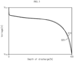
- FIG. 3 is a diagram referenced in describing a result of normalizing the measured voltage curve
- FIG. 4 is a diagram referenced in describing a differential voltage curve corresponding to the measured voltage curve
- FIG. 5 is a diagram referenced in describing an operation of determining overvoltage characteristics from the differential voltage curve.
- the battery evaluation system 1 is provided to evaluate the overvoltage characteristics of a battery B.
- the battery B may be a lithium ion battery.
- the battery B is not limited to a particular type and may include any type of battery that can be recharged repeatedly.
- the battery evaluation system 1 includes an overvoltage characteristics evaluation apparatus 10 (hereinafter referred to as the 'evaluation apparatus') and a charge/discharge device 20.
- an overvoltage characteristics evaluation apparatus 10 hereinafter referred to as the 'evaluation apparatus'
- a charge/discharge device 20 hereinafter referred to as the 'evaluation apparatus'
- the charge/discharge device 20 is electrically connected to a current path for the charge/discharge of the battery B. That is, the charge/discharge device 20 is provided to be electrically connectable to the battery B in parallel through a pair of terminals.
- the charge/discharge device 20 may include a constant current circuit to adjust a current rate (referred to as 'C-rate') of the electric current flowing through the battery B.
- the charge/discharge device 20 is configured to adjust the current rate (referred to as 'C-rate') of the electric current for the charge or discharge of the battery B in response to a command from the evaluation apparatus 10.
- the charge/discharge device 20 may provide only one of a constant current discharging function and a constant current charging function.
- the evaluation apparatus 10 includes a sensing unit 110 and a control unit 120.
- the evaluation apparatus 10 may further include at least one of an interface unit 130 or a temperature chamber 140. The following description is made under the assumption that the evaluation apparatus 10 includes all the sensing unit 110, the control unit 120, the interface unit 130 and the temperature chamber 140.
- the sensing unit 110 includes a voltage sensor 111 and a current sensor 112.
- the voltage sensor 111 is provided to be electrically connectable to the battery B in parallel.
- the voltage sensor 111 is configured to measure a voltage across the battery B, and generate a voltage signal indicating the measured voltage.
- the current sensor 112 is provided to be electrically connectable to the battery B in series through the current path connecting the battery B and the charge/discharge device 20.
- the current sensor 112 is configured to measure the electric current flowing through the battery B, and generate a current signal indicating the measured current.
- the control unit 120 may collect sensing information including the voltage signal and the current signal obtained in synchronization from the sensing unit 110.
- the control unit 120 may be implemented in hardware using at least one of application specific integrated circuits (ASICs), digital signal processors (DSPs), digital signal processing devices (DSPDs), programmable logic devices (PLDs), field programmable gate arrays (FPGAs), microprocessors or electrical units for performing the other functions.
- the control unit 120 may have a memory embedded therein.
- the memory may include, for example, at least one type of storage medium of flash memory type, hard disk type, Solid State Disk (SSD) type, Silicon Disk Drive (SDD) type, multimedia card micro type, random access memory (RAM), static random access memory (SRAM), read-only memory (ROM), electrically erasable programmable read-only memory (EEPROM) or programmable read-only memory (PROM).
- the memory may store data and programs required for the computation operation (methods as described below) by the control unit 120.
- the control unit 120 may record data indicating the result of the computation operation in the memory.
- the control unit 120 is operably coupled to the charge/discharge device 20, the sensing unit 110, the interface unit 130 and the temperature chamber 140. Operably coupled refers to directly/indirectly connected to transmit and receive a signal in one or two directions.
- the interface unit 130 is configured to support wired or wireless communication between the control unit 120 and a user terminal 2 (for example, a personal computer).
- the wired communication may be, for example, controller area network (CAN) communication
- the wireless communication may be, for example, Zigbee or Bluetooth communication.
- the communication protocol is not limited to a particular type and may include any communication protocol that supports wired/wireless communication between the control unit 120 and the user terminal 2.
- the interface unit 130 may include an output device (for example, a display, a speaker) to provide the information received from the control unit 120 and/or the user terminal 2 in a recognizable format.
- the control unit 120 may determine a measured capacity history and a measured voltage history based on the sensing information (i.e., time-series of the measured current values and time-series of the measured voltage values) collected from the sensing unit 110 at a preset time interval during a discharge event of the battery B.
- the measured capacity history indicates a time-series change in the discharge capacity of the battery B from beginning to end of the discharge event.
- the measured voltage history indicates a time-series change in the voltage of the battery B from beginning to end of the discharge event. In the discharge event, a larger discharge capacity of the measured capacity history corresponds to a lower voltage of the measured voltage history.
- the control unit 120 may record the measured capacity history and the measured voltage history in the memory.
- the discharge event may include constant current discharging.
- the discharge event may be executed while the temperature chamber 140 maintains the ambient temperature of the battery B at a preset temperature.
- the constant current discharging is performed from a first time point at which the voltage of the battery B is equal to a first threshold voltage V TH1 to a second time point at which the voltage of the battery B is equal to a second threshold voltage V TH2 that is lower than the first threshold voltage V TH1 .
- the first threshold voltage V TH1 is an Open Circuit Voltage (OCV) of the battery B when the battery B is fully charged, and may be the same as a preset value, i.e., end-of-charge voltage.
- the second threshold voltage V TH2 may be equal to a preset value as the OCV when the battery B is fully discharged, i.e., an end-of-discharge voltage.
- the C-rate of constant current discharging may be, for example, a high current of 6.5 C-rate.
- a first reference voltage curve 210 is pre-acquired through the discharge event for a reference battery (not shown) having undergone reference pretreatment, and a first measured voltage curve 220 is acquired through the discharge event for the battery B having undergone polarization-inducing pretreatment.
- the first reference voltage curve 210 indicates a correlation between a reference capacity history and a reference voltage history.
- the reference capacity history indicates a time-series change in the discharge capacity of the reference battery from beginning to end of the discharge event.
- the reference voltage history indicates a time-series change in the voltage of the reference battery from beginning to end of the discharge event.
- the battery B and the reference battery are manufactured with the same electrical and chemical characteristics.
- the reference pretreatment may include a series of the following processes.
- the polarization-inducing pretreatment may include a series of the following processes.
- the polarization-inducing pretreatment in which the battery B is placed at a second temperature (room temperature), instead of a first temperature (high temperature), is different from the reference pretreatment. Due to this difference, the reference battery undergoes the discharge event in a state that polarization completely disappeared, whereas the battery B undergoes the discharge event in a state that the battery B is still polarized.
- the reference pretreatment is not limited to the above-described example when the reference pretreatment is performed to reduce the polarization of the battery B to below a predetermined level at the start of the discharge event.
- the polarization-inducing pretreatment is not limited to the above-described example when it is performed to form larger polarization in the battery B than the reference pretreatment.
- the control unit 120 may control the charge/discharge device 20 and the temperature chamber 140 to perform the processes of the polarization-inducing pretreatment in a sequential order.
- the temperature chamber 140 is a device having an internal space in which the battery B may be received, and the temperature of the internal space (i.e., the ambient temperature of the battery B) may be detected and adjusted.
- the control unit 120 may perform the discharge event for the battery B.
- the polarization-inducing pretreatment may be performed using a separate tester instead of the evaluation apparatus 10.
- the first measured voltage curve 220 shows voltage decrease behaviors generally faster than the first reference voltage curve 210, and it can be seen that the total discharge capacity Q B_total of the battery B corresponding to the second threshold voltage V TH2 decreases from the total discharge capacity Q ref_total of the reference battery. This is because polarization remaining in the battery B is exhibited as overvoltage by the electric current of the discharge event.
- the control unit 120 may determine a first depth of discharge history and a second depth of discharge history having the same range of 0-1 or 0-100% by normalizing the reference capacity history of the first reference voltage curve 210 and the measured capacity history of the first measured voltage curve 220, respectively.
- the reference capacity history of the first reference voltage curve 210 and the first depth of discharge history may have the following relation.
- DoD ref i Q ref i Q ref _ total ⁇ 100 %
- Q ref_total is the total discharge capacity of the first reference voltage curve 210
- Q ref [i] is the discharge capacity of the reference battery determined at the i th time during the discharge event
- DoD ref [i] is a value obtained by normalizing Q ref [i] using Q ref_total .
- the first depth of discharge history may be a set (time-series) of DoD ref [i] during the discharge event.
- the measured capacity history of the first measured voltage curve 220 and the second depth of discharge history may have the following relation.
- DoD bat j Q B j Q B _ total ⁇ 100 %
- Q B_total is the total discharge capacity of the first measured voltage curve 220
- Q B [j] is the discharge capacity of the battery B determined at the i th time during the discharge event
- DoD B [j] is a value obtained by normalizing Q B [j] using Q B_total .
- the second depth of discharge history may be a set (time-series) of DoD B [j] during the discharge event.
- the control unit 120 may determine a second reference voltage curve 310 from the first reference voltage curve 210 by converting a correlation between the reference capacity history and the reference voltage history to a correlation between the first depth of discharge history and the reference voltage history.
- control unit 120 may determine a second measured voltage curve 320 from the first measured voltage curve 220 by converting a correlation between the measured capacity history and the measured voltage history of the first measured voltage curve 220 to a correlation between the second depth of discharge history and the measured voltage history.
- the reference voltage history of the second reference voltage curve 310 and the measured voltage history of the second measured voltage curve 320 are scaled with respect to the depth of discharge in the common range of 0-100%.
- the X axis indicates a differential voltage
- the Y axis horizontal axis
- the differential voltage dV/dQ is a ratio of a change dV in voltage to a change dQ in discharge capacity (or depth of discharge).
- control unit 120 may determine a reference differential voltage curve 410 from the second reference voltage curve 310 by differentiating the reference voltage history of the second reference voltage curve 310 with respect to the first depth of discharge history.
- the reference differential voltage curve 410 may be recorded in the memory according to a result of a test conducted in advance, instead of being determined by the control unit 120. That is, the reference differential voltage curve 410 may be preset as a differential voltage curve when the discharge event is executed in a zero polarization state of the battery B, i.e., the battery B did not yet undergo the polarization-inducing pretreatment, and.
- the control unit 120 may determine a differential voltage curve 420 from the second measured voltage curve 320 by differentiating the measured voltage history of the second measured voltage curve 320 with respect to the second depth of discharge history.
- the differential voltage curve 420 may indicate a time-series of a ratio of a change in voltage to (i) the depth of discharge (or its corresponding discharge capacity) and (ii) a unit change of the depth of discharge (or a change of corresponding discharge capacity, in the entire range of 0-100%.
- the control unit 120 determines overvoltage characteristics information of the battery B from the differential voltage curve 420 by comparing the reference differential voltage curve 410 with the differential voltage curve 420.
- the control unit 120 may associate the overvoltage characteristics information to the polarization-inducing pretreatment and record in the memory.
- FIG. 5 is a graph exemplarily showing a polarization comparison curve 500 indicating a correlation between a differential voltage difference ⁇ dV/dQ and the depth of discharge over a reference range ⁇ R ref .
- the X axis (vertical axis) indicates the differential voltage difference ⁇ dV/dQ
- the Y axis (horizontal axis) is the same as the Y axis of FIG. 4 .
- the control unit 120 may determine the differential voltage difference ⁇ dV/dQ between the reference differential voltage curve 410 and the differential voltage curve 420 with respect to the depth of discharge in the reference range ⁇ R ref .
- the differential voltage difference ⁇ dV/dQ corresponding to each depth of discharge may be a value obtained by subtracting the differential voltage of the reference differential voltage curve 410 from the differential voltage of the differential voltage curve 420.
- the reference range ⁇ R ref is from a predetermined first depth of discharge DoD 1 (for example, 10%) larger than 0% to a predetermined second depth of discharge DoD 2 (for example, 90%) smaller than 100%.
- the reason of using the reference range ⁇ R ref is that the discharge reaction of the battery B is very unstable in the range of 0 % ⁇ the first depth of discharge DoD 1 and the range of the second depth of discharge DoD 2 ⁇ 100%.
- the control unit 120 may determine a concentrated overvoltage range ⁇ R op , i.e., a range in which the differential voltage difference ⁇ dV/dQ of the polarization comparison curve 500 is equal to or larger than a threshold difference ⁇ D in the entire range (i.e., 0 ⁇ 100%) of the depth of discharge history.
- the overvoltage characteristics information may include the concentrated overvoltage range ⁇ R op .
- the differential voltage of the differential voltage curve 420 is kept higher by at least the threshold difference ⁇ D than the differential voltage of the reference differential voltage curve 410 over the concentrated overvoltage range ⁇ R op from the first depth of discharge DoD A to the second depth of discharge DoD B .
- the threshold difference ⁇ D may be a preset value.
- the control unit 120 may determine the threshold difference ⁇ D based on an integral value of the differential voltage difference ⁇ dV/dQ over the reference range ⁇ R ref .
- the control unit 120 may determine the threshold difference ⁇ D to be equal to a value obtained by dividing the integral value by the size of the reference range ⁇ R ref (i.e., DoD 2 - DoD 1 ).
- the control unit 120 may be further configured to determine an area of a concentrated overvoltage zone 430.
- the concentrated overvoltage zone 430 is a zone defined by the concentrated overvoltage range ⁇ R op , the differential voltage curve 420 and the reference differential voltage curve 410.
- the area of the concentrated overvoltage zone 430 is a difference between a voltage change of the second measured voltage curve 320 and a voltage change of the second reference voltage curve 310 over the concentrated overvoltage range ⁇ R op . That is, the area of the concentrated overvoltage zone 430 indicates the magnitude of overvoltage accumulated in the battery B over the concentrated overvoltage range ⁇ R op .
- the overvoltage characteristics information may further include the area the concentrated overvoltage zone.
- FIG. 6 is a flowchart exemplarily showing a method for evaluating overvoltage characteristics of a battery according to a first embodiment of the present disclosure. The method of FIG. 6 is performed after the polarization-inducing pretreatment for the battery B is completed.
- the control unit 120 determines a measured capacity history and a measured voltage history indicating a time-series change in capacity and voltage of the battery B during the discharge event of the battery B, respectively.
- the measured capacity history is based on the accumulated value of the electric current measured by the current sensor 112 at a predetermined time interval during the discharge event.
- the measured voltage history is based on the voltage across the battery B measured by the voltage sensor 111 at the predetermined time interval during the discharge event.
- step S620 the control unit 120 determines a first measured voltage curve 220 indicating a correlation between the measured capacity history and the measured voltage history.
- step S630 the control unit 120 determines a second measured voltage curve 320 indicating a correlation between a depth of discharge history corresponding to the measured capacity history and the measured voltage history by normalizing the measured capacity history to the total discharge capacity Q B_total of the measured capacity history.
- step S640 the control unit 120 determines a differential voltage curve 420 from the second measured voltage curve 320 by differentiating the measured voltage history with respect to the depth of discharge history.
- step S650 the control unit 120 determines a differential voltage difference between the differential voltage curve and the reference differential voltage curve with respect to the depth of discharge in the reference range ⁇ R ref .
- step S660 the control unit 120 determines a concentrated overvoltage range ⁇ R op , i.e., a range in which the differential voltage difference is equal to or larger than a threshold difference ⁇ D in the reference range ⁇ R ref .
- the threshold difference ⁇ D may be pre-recorded in the memory.
- step S670 the control unit 120 determines an area of a concentrated overvoltage zone 430 defined by the concentrated overvoltage range ⁇ R op , the differential voltage curve 420 and the reference differential voltage curve 410.
- the step S670 may be omitted from the method of FIG. 6 .
- step S680 the control unit 120 outputs an evaluation message indicating overvoltage characteristics information of the battery B.
- the overvoltage characteristics information includes at least one of the concentrated overvoltage range ⁇ R op or the area of the concentrated overvoltage zone 430.
- the interface unit 130 may transmit the evaluation message to the user terminal 2 or output visual and/or audible information corresponding to the evaluation message.
- FIG. 7 is a flowchart exemplarily showing a method for evaluating overvoltage characteristics of a battery according to a second embodiment of the present disclosure. The method of FIG. 7 is performed after the polarization-inducing pretreatment for the battery B is completed. In describing the second embodiment, a repeated description in common with the first embodiment may be omitted herein.
- step S710 the control unit 120 determines a measured capacity history and a measured voltage history indicating a time-series change in capacity and voltage of the battery B during the discharge event of the battery B.
- step S720 the control unit 120 determines a first measured voltage curve 220 indicating a correlation between the measured capacity history and the measured voltage history.
- step S730 the control unit 120 determines a second measured voltage curve 320 indicating a correlation between a depth of discharge history corresponding to the measured capacity history and the measured voltage history by normalizing the measured capacity history to the total discharge capacity Q B_total of the measured capacity history.
- step S740 the control unit 120 determines a differential voltage curve 420 from the second measured voltage curve 320 by differentiating the measured voltage history with respect to the depth of discharge history.
- step S750 the control unit 120 determines a differential voltage difference between the differential voltage curve 420 and the reference differential voltage curve 410 with respect to the depth of discharge in the reference range ⁇ R ref .
- step S752 the control unit 120 determines whether an integral value of the differential voltage difference over the reference range ⁇ R ref is larger than a reference integral value.
- step S756 is performed.
- the value of the step S752 being “No” may indicate that a computation error occurred in the steps S710-S750.
- step S754 is performed.
- step S754 the control unit 120 outputs a fault message.
- the interface unit 130 may transmit the fault message to the user terminal 2 or output visual and/or audible information corresponding to the fault message.
- the steps S752 and S754 may be omitted from the method of FIG. 7 , and after the step S750, step S756 may be performed.
- step S756 the control unit 120 determines a threshold difference ⁇ D based on the integral value of the differential voltage difference over the reference range ⁇ R ref .
- step S760 the control unit 120 determines a concentrated overvoltage range ⁇ R op , i.e., a range in which the differential voltage difference is equal to or larger than the threshold difference ⁇ D in the reference range ⁇ R ref .
- step S770 the control unit 120 determines an area of a concentrated overvoltage zone 430 defined by the concentrated overvoltage range ⁇ R op , the differential voltage curve 420 and the reference differential voltage curve 410.
- the step S770 may be omitted from the method of FIG. 7 .
- step S780 the control unit 120 outputs an evaluation message indicating overvoltage characteristics information of the battery B.
- the overvoltage characteristics information includes at least one of the threshold difference ⁇ D, the concentrated overvoltage range ⁇ R op or the area of the concentrated overvoltage zone 430.
Landscapes
- Physics & Mathematics (AREA)
- General Physics & Mathematics (AREA)
- Secondary Cells (AREA)
- Tests Of Electric Status Of Batteries (AREA)
- Charge And Discharge Circuits For Batteries Or The Like (AREA)
Abstract
Description
- The present disclosure relates to evaluation technology of polarization induced overvoltage characteristics of a battery.
- The present application claims the benefit of
Korean Patent Application No. 10-2020-0096200 filed on July 31, 2020 - Recently, there has been a rapid increase in the demand for portable electronic products such as laptop computers, video cameras and mobile phones, and with the extensive development of electric vehicles, accumulators for energy storage, robots and satellites, many studies are being made on high performance batteries that can be repeatedly recharged.
- Currently, commercially available batteries include nickel-cadmium batteries, nickel-hydrogen batteries, nickel-zinc batteries, lithium batteries and the like, and among them, lithium batteries have little or no memory effect, and thus they are gaining more attention than nickel-based batteries for their advantages that recharging can be done whenever it is convenient, the self-discharge rate is very low and the energy density is high.
- In predicting the performance of a battery, for example, State Of Health (SOH) and State Of Charge (SOC), voltage and current are basically required battery parameters. The capacity of the battery (or its change) may be determined based on the measured current using Coulomb counting.
- Differential Voltage Analysis (DVA) determines a differential voltage curve by differentiating a measured voltage curve indicating a correlation between capacity and voltage of the battery, and determines a degradation parameter of the battery based on a change in size and/or position of feature(s) in the differential voltage curve. The degradation parameter includes, for example, a capacity loss of the positive or negative electrode, lithium deposition, etc.
- In determining the degradation parameter using DVA, overvoltage reflected on the measured voltage curve acts as noise in the differential voltage curve due to polarization (for example, a concentration gradient on active material surface). Accordingly, to suppress the polarization causing overvoltage, a process of obtaining the measured voltage curve is usually performed by intermittently discharging or charging the battery with low current (for example, less than 0.5 C-rate). As a result, the polarization induced overvoltage is a key parameter that affects the degradation of the battery, but the existing DVA is difficult to obtain the overvoltage characteristics of the battery.
- Additionally, to develop batteries having high safety and performance, it is important to identify a correlation between polarization dependent on the use condition of the battery and its resulting overvoltage characteristics.
- The present disclosure is designed to solve the above-described problem, and therefore the present disclosure is directed to providing an apparatus and method for evaluating overvoltage characteristics of a battery using Differential Voltage Analysis (DVA).
- These and other objects and advantages of the present disclosure may be understood by the following description and will be apparent from the embodiments of the present disclosure. In addition, it will be readily understood that the objects and advantages of the present disclosure may be realized by the means set forth in the appended claims and a combination thereof.
- An overvoltage characteristics evaluation apparatus for a battery according to an aspect of the present disclosure includes a sensing unit configured to measure a current and a voltage of the battery, and a control unit configured to determine a measured capacity history and a measured voltage history indicating a time-series change in capacity and voltage of the battery using sensing information obtained from the sensing unit during a discharge event executed subsequent to polarization-inducing pretreatment for the battery. The control unit is configured to determine a first measured voltage curve indicating a correlation between the measured capacity history and the measured voltage history. The control unit is configured to determine a second measured voltage curve indicating a correlation between a depth of discharge history obtained by normalizing the measured capacity history to a total discharge capacity of the measured capacity history and the measured voltage history. The control unit is configured to determine a differential voltage curve from the second measured voltage curve by differentiating the measured voltage history with respect to the depth of discharge history. The control unit is configured to determine overvoltage characteristics information associated with the polarization-inducing pretreatment by comparing the differential voltage curve with a reference differential voltage curve.
- The discharge event may include constant current discharging from a first time point to a second time point. The first time point is a time point at which the voltage of the battery is equal to a first threshold voltage. The second time point is a time point at which the voltage of the battery is equal to a second threshold voltage that is lower than the first threshold voltage.
- The control unit may be configured to determine a concentrated overvoltage range which is a range in which a differential voltage difference between the differential voltage curve and the reference differential voltage curve is equal to or larger than a threshold difference in an entire range of the depth of discharge history. The overvoltage characteristics information includes the concentrated overvoltage range.
- The control unit may be configured to determine an area of a concentrated overvoltage zone defined by the concentrated overvoltage range, the differential voltage curve and the reference differential voltage curve. The overvoltage characteristics information further includes the area of the concentrated overvoltage zone.
- The area indicates a magnitude of overvoltage accumulated in the battery over the concentrated overvoltage range.
- The control unit may be configured to determine the threshold difference by dividing an integral value of the differential voltage difference over a reference range of from a predetermined first depth of discharge to a predetermined second depth of discharge in the entire range of the depth of discharge history by a size of the reference range.
- The control unit may be configured to determine the concentrated overvoltage range in the reference range.
- An overvoltage characteristics evaluation method for a battery according to another aspect of the present disclosure includes determining a measured capacity history and a measured voltage history indicating a time-series change of capacity and voltage of the battery using sensing information of current and voltage of the battery obtained during a discharge event executed subsequent to polarization-inducing pretreatment for the battery, determining a first measured voltage curve indicating a correlation between the measured capacity history and the measured voltage history, determining a second measured voltage curve indicating a correlation between a depth of discharge history obtained by normalizing the measured capacity history to a total discharge capacity of the measured capacity history and the measured voltage history, determining a differential voltage curve from the second measured voltage curve by differentiating the measured voltage history with respect to the depth of discharge history, and determining overvoltage characteristics information associated with the polarization-inducing pretreatment by comparing the differential voltage curve with a reference differential voltage curve.
- The step of determining the overvoltage characteristics information associated with the polarization-inducing pretreatment may include determining a concentrated overvoltage range which is a range in which a differential voltage difference between the differential voltage curve and the reference differential voltage curve in an entire range of the depth of discharge history is equal to or larger than a threshold difference.
- The step of determining the overvoltage characteristics information associated with the polarization-inducing pretreatment may further include determining an area of a concentrated overvoltage zone defined by the concentrated overvoltage range, the differential voltage curve and the reference differential voltage curve.
- According to at least one of the embodiments of the present disclosure, it is possible to evaluate overvoltage characteristics of a battery using Differential Voltage Analysis (DVA). In particular, a correlation between a measured voltage history and a measured capacity history may be converted to a correlation between the measured voltage history and a depth of discharge history. Here, the depth of discharge history may be obtained by normalizing the measured capacity history of a measured voltage curve obtained during a discharge event executed subsequent to polarization-inducing pretreatment for the battery to the depth of discharge history (in the range of 0~100%). Accordingly, it is possible to obtain, as a result of evaluation, a concentrated overvoltage range in which the overvoltage characteristics of the battery having undergone the polarization-inducing pretreatment are exhibited in a concentrated manner.
- In addition, according to at least one of the embodiments of the present disclosure, it is possible to additionally obtain the magnitude of overvoltage accumulated over the concentrated overvoltage range as a result of evaluation.
- The effects of the present disclosure are not limited to the effects mentioned above, and these and other effects will be clearly understood by those skilled in the art from the appended claims.
- The accompanying drawings illustrate a preferred embodiment of the present disclosure, and together with the detailed description of the present disclosure described below, serve to provide a further understanding of the technical aspects of the present disclosure, and thus the present disclosure should not be construed as being limited to the drawings.
-
FIG. 1 is a diagram exemplarily showing a configuration of a battery evaluation system according to the present disclosure. -
FIG. 2 is a diagram referenced in describing a relationship between a magnitude of overvoltage and a measured voltage curve. -
FIG. 3 is a diagram referenced in describing a result of normalizing a measured voltage curve. -
FIG. 4 is a diagram referenced in describing a differential voltage curve corresponding to a measured voltage curve. -
FIG. 5 is a diagram referenced in describing an operation of determining overvoltage characteristics from a differential voltage curve. -
FIG. 6 is a flowchart exemplarily showing a method for evaluating overvoltage characteristics of a battery according to a first embodiment of the present disclosure. -
FIG. 7 is a flowchart exemplarily showing a method for evaluating overvoltage characteristics of a battery according to a second embodiment of the present disclosure. - Hereinafter, the preferred embodiments of the present disclosure will be described in detail with reference to the accompanying drawings. Prior to the description, it should be understood that the terms or words used in the specification and the appended claims should not be construed as being limited to general and dictionary meanings, but rather interpreted based on the meanings and concepts corresponding to the technical aspects of the present disclosure on the basis of the principle that the inventor is allowed to define the terms appropriately for the best explanation.
- Therefore, the embodiments described herein and illustrations shown in the drawings are just a most preferred embodiment of the present disclosure, but not intended to fully describe the technical aspects of the present disclosure, so it should be understood that a variety of other equivalents and modifications could have been made thereto at the time that the application was filed.
- The terms including the ordinal number such as "first", "second" and the like, are used to distinguish one element from another among various elements, but not intended to limit the elements by the terms.
- Unless the context clearly indicates otherwise, it will be understood that the term "comprises" when used in this specification, specifies the presence of stated elements, but does not preclude the presence or addition of one or more other elements. Additionally, the term "control unit" as used herein refers to a processing unit of at least one function or operation, and this may be implemented by hardware and software either alone or in combination.
- In addition, throughout the specification, it will be further understood that when an element is referred to as being "connected to" another element, it can be directly connected to the other element or intervening elements may be present.
-
FIG. 1 is a diagram exemplarily showing a configuration of a battery evaluation system according to the present disclosure,FIG. 2 is a diagram referenced in describing a relationship between a magnitude of overvoltage and a measured voltage curve,FIG. 3 is a diagram referenced in describing a result of normalizing the measured voltage curve,FIG. 4 is a diagram referenced in describing a differential voltage curve corresponding to the measured voltage curve, andFIG. 5 is a diagram referenced in describing an operation of determining overvoltage characteristics from the differential voltage curve. - Referring to
FIG. 1 , thebattery evaluation system 1 is provided to evaluate the overvoltage characteristics of a battery B. The battery B may be a lithium ion battery. The battery B is not limited to a particular type and may include any type of battery that can be recharged repeatedly. - The
battery evaluation system 1 includes an overvoltage characteristics evaluation apparatus 10 (hereinafter referred to as the 'evaluation apparatus') and a charge/discharge device 20. - The charge/
discharge device 20 is electrically connected to a current path for the charge/discharge of the battery B. That is, the charge/discharge device 20 is provided to be electrically connectable to the battery B in parallel through a pair of terminals. The charge/discharge device 20 may include a constant current circuit to adjust a current rate (referred to as 'C-rate') of the electric current flowing through the battery B. The charge/discharge device 20 is configured to adjust the current rate (referred to as 'C-rate') of the electric current for the charge or discharge of the battery B in response to a command from theevaluation apparatus 10. The charge/discharge device 20 may provide only one of a constant current discharging function and a constant current charging function. - The
evaluation apparatus 10 includes asensing unit 110 and acontrol unit 120. Theevaluation apparatus 10 may further include at least one of aninterface unit 130 or atemperature chamber 140. The following description is made under the assumption that theevaluation apparatus 10 includes all thesensing unit 110, thecontrol unit 120, theinterface unit 130 and thetemperature chamber 140. - The
sensing unit 110 includes a voltage sensor 111 and acurrent sensor 112. - The voltage sensor 111 is provided to be electrically connectable to the battery B in parallel. The voltage sensor 111 is configured to measure a voltage across the battery B, and generate a voltage signal indicating the measured voltage.
- The
current sensor 112 is provided to be electrically connectable to the battery B in series through the current path connecting the battery B and the charge/discharge device 20. Thecurrent sensor 112 is configured to measure the electric current flowing through the battery B, and generate a current signal indicating the measured current. - The
control unit 120 may collect sensing information including the voltage signal and the current signal obtained in synchronization from thesensing unit 110. - The
control unit 120 may be implemented in hardware using at least one of application specific integrated circuits (ASICs), digital signal processors (DSPs), digital signal processing devices (DSPDs), programmable logic devices (PLDs), field programmable gate arrays (FPGAs), microprocessors or electrical units for performing the other functions. Thecontrol unit 120 may have a memory embedded therein. The memory may include, for example, at least one type of storage medium of flash memory type, hard disk type, Solid State Disk (SSD) type, Silicon Disk Drive (SDD) type, multimedia card micro type, random access memory (RAM), static random access memory (SRAM), read-only memory (ROM), electrically erasable programmable read-only memory (EEPROM) or programmable read-only memory (PROM). The memory may store data and programs required for the computation operation (methods as described below) by thecontrol unit 120. Thecontrol unit 120 may record data indicating the result of the computation operation in the memory. - The
control unit 120 is operably coupled to the charge/discharge device 20, thesensing unit 110, theinterface unit 130 and thetemperature chamber 140. Operably coupled refers to directly/indirectly connected to transmit and receive a signal in one or two directions. - The
interface unit 130 is configured to support wired or wireless communication between thecontrol unit 120 and a user terminal 2 (for example, a personal computer). The wired communication may be, for example, controller area network (CAN) communication, and the wireless communication may be, for example, Zigbee or Bluetooth communication. The communication protocol is not limited to a particular type and may include any communication protocol that supports wired/wireless communication between thecontrol unit 120 and theuser terminal 2. Theinterface unit 130 may include an output device (for example, a display, a speaker) to provide the information received from thecontrol unit 120 and/or theuser terminal 2 in a recognizable format. - The
control unit 120 may determine a measured capacity history and a measured voltage history based on the sensing information (i.e., time-series of the measured current values and time-series of the measured voltage values) collected from thesensing unit 110 at a preset time interval during a discharge event of the battery B. The measured capacity history indicates a time-series change in the discharge capacity of the battery B from beginning to end of the discharge event. The measured voltage history indicates a time-series change in the voltage of the battery B from beginning to end of the discharge event. In the discharge event, a larger discharge capacity of the measured capacity history corresponds to a lower voltage of the measured voltage history. - The
control unit 120 may record the measured capacity history and the measured voltage history in the memory. The discharge event may include constant current discharging. The discharge event may be executed while thetemperature chamber 140 maintains the ambient temperature of the battery B at a preset temperature. - The constant current discharging is performed from a first time point at which the voltage of the battery B is equal to a first threshold voltage VTH1 to a second time point at which the voltage of the battery B is equal to a second threshold voltage VTH2 that is lower than the first threshold voltage VTH1. For example, the first threshold voltage VTH1 is an Open Circuit Voltage (OCV) of the battery B when the battery B is fully charged, and may be the same as a preset value, i.e., end-of-charge voltage. The second threshold voltage VTH2 may be equal to a preset value as the OCV when the battery B is fully discharged, i.e., an end-of-discharge voltage. The C-rate of constant current discharging may be, for example, a high current of 6.5 C-rate.
- In
FIG. 2 , the X axis (vertical axis) indicates voltage, and the Y axis (horizontal axis) indicates discharge capacity. A firstreference voltage curve 210 is pre-acquired through the discharge event for a reference battery (not shown) having undergone reference pretreatment, and a first measuredvoltage curve 220 is acquired through the discharge event for the battery B having undergone polarization-inducing pretreatment. The firstreference voltage curve 210 indicates a correlation between a reference capacity history and a reference voltage history. The reference capacity history indicates a time-series change in the discharge capacity of the reference battery from beginning to end of the discharge event. The reference voltage history indicates a time-series change in the voltage of the reference battery from beginning to end of the discharge event. The battery B and the reference battery are manufactured with the same electrical and chemical characteristics. - Below is an example of each of reference pretreatment and polarization-inducing pretreatment.
- <Reference pretreatment> The reference pretreatment may include a series of the following processes.
- Fully discharge using a predetermined first current profile from a predetermined SOC (for example, 30%)
- Place at a predetermined first temperature (for example, 80°C) for a predetermined first time (for example, 6 hours)
- Fully charge using a predetermined second current profile
- <Polarization-inducing pretreatment> The polarization-inducing pretreatment may include a series of the following processes.
- Fully discharge using a predetermined first current profile from a predetermined SOC (for example, 30%)
- Place at a predetermined second temperature (for example, 25°C) for a predetermined second time (for example, 3 hours)
- Fully charge using a predetermined second current profile
- When comparing the reference pretreatment with the polarization-inducing pretreatment in the above-described example, the polarization-inducing pretreatment in which the battery B is placed at a second temperature (room temperature), instead of a first temperature (high temperature), is different from the reference pretreatment. Due to this difference, the reference battery undergoes the discharge event in a state that polarization completely disappeared, whereas the battery B undergoes the discharge event in a state that the battery B is still polarized. The reference pretreatment is not limited to the above-described example when the reference pretreatment is performed to reduce the polarization of the battery B to below a predetermined level at the start of the discharge event. Likewise, the polarization-inducing pretreatment is not limited to the above-described example when it is performed to form larger polarization in the battery B than the reference pretreatment.
- After the user puts the battery B in the
temperature chamber 140, the user may request theevaluation apparatus 10 to perform polarization-inducing pretreatment. In response to the request received from theuser terminal 2 through theinterface unit 130, thecontrol unit 120 may control the charge/discharge device 20 and thetemperature chamber 140 to perform the processes of the polarization-inducing pretreatment in a sequential order. Thetemperature chamber 140 is a device having an internal space in which the battery B may be received, and the temperature of the internal space (i.e., the ambient temperature of the battery B) may be detected and adjusted. In response to the completion of the polarization-inducing pretreatment, thecontrol unit 120 may perform the discharge event for the battery B. Alternatively, the polarization-inducing pretreatment may be performed using a separate tester instead of theevaluation apparatus 10. - It can be seen from
FIG. 2 that a difference between the firstreference voltage curve 210 and the first measuredvoltage curve 220 corresponding to a polarization difference between the battery B and the reference battery occurs during the discharge event. Specifically, the first measuredvoltage curve 220 shows voltage decrease behaviors generally faster than the firstreference voltage curve 210, and it can be seen that the total discharge capacity QB_total of the battery B corresponding to the second threshold voltage VTH2 decreases from the total discharge capacity Qref_total of the reference battery. This is because polarization remaining in the battery B is exhibited as overvoltage by the electric current of the discharge event. - As a result, the reference voltage history of the first
reference voltage curve 210 and the measured voltage history of the first measuredvoltage curve 220 have the same voltage range, but the reference capacity history of the firstreference voltage curve 210 and the measured capacity history of the first measuredvoltage curve 220 do not have the same capacity range. Accordingly, for easy comparison between the firstreference voltage curve 210 and the first measuredvoltage curve 220, thecontrol unit 120 may determine a first depth of discharge history and a second depth of discharge history having the same range of 0-1 or 0-100% by normalizing the reference capacity history of the firstreference voltage curve 210 and the measured capacity history of the first measuredvoltage curve 220, respectively. - The reference capacity history of the first
reference voltage curve 210 and the first depth of discharge history may have the following relation.
- When i is a natural number of 1 or greater, Qref_total is the total discharge capacity of the first
reference voltage curve 210, Qref[i] is the discharge capacity of the reference battery determined at the ith time during the discharge event, and DoDref[i] is a value obtained by normalizing Qref[i] using Qref_total. The first depth of discharge history may be a set (time-series) of DoDref[i] during the discharge event. - The measured capacity history of the first measured
voltage curve 220 and the second depth of discharge history may have the following relation.
- When j is a natural number of 1 or greater, QB_total is the total discharge capacity of the first measured
voltage curve 220, QB[j] is the discharge capacity of the battery B determined at the ith time during the discharge event, and DoDB[j] is a value obtained by normalizing QB[j] using QB_total. The second depth of discharge history may be a set (time-series) of DoDB[j] during the discharge event. - In
FIG. 3 , the X axis (vertical axis) indicates voltage, and the Y axis (horizontal axis) indicates the depth of discharge corresponding to the discharge capacity ofFIG. 2 . Referring toFIG. 3 , thecontrol unit 120 may determine a secondreference voltage curve 310 from the firstreference voltage curve 210 by converting a correlation between the reference capacity history and the reference voltage history to a correlation between the first depth of discharge history and the reference voltage history. - Likewise, the
control unit 120 may determine a second measuredvoltage curve 320 from the first measuredvoltage curve 220 by converting a correlation between the measured capacity history and the measured voltage history of the first measuredvoltage curve 220 to a correlation between the second depth of discharge history and the measured voltage history. As a result, the reference voltage history of the secondreference voltage curve 310 and the measured voltage history of the second measuredvoltage curve 320 are scaled with respect to the depth of discharge in the common range of 0-100%. - In
FIG. 4 , the X axis (vertical axis) indicates a differential voltage, the Y axis (horizontal axis) is the same as the Y axis ofFIG. 3 . The differential voltage dV/dQ is a ratio of a change dV in voltage to a change dQ in discharge capacity (or depth of discharge). - Referring to
FIG. 4 , thecontrol unit 120 may determine a referencedifferential voltage curve 410 from the secondreference voltage curve 310 by differentiating the reference voltage history of the secondreference voltage curve 310 with respect to the first depth of discharge history. - Alternatively, the reference
differential voltage curve 410 may be recorded in the memory according to a result of a test conducted in advance, instead of being determined by thecontrol unit 120. That is, the referencedifferential voltage curve 410 may be preset as a differential voltage curve when the discharge event is executed in a zero polarization state of the battery B, i.e., the battery B did not yet undergo the polarization-inducing pretreatment, and. - The
control unit 120 may determine adifferential voltage curve 420 from the second measuredvoltage curve 320 by differentiating the measured voltage history of the second measuredvoltage curve 320 with respect to the second depth of discharge history. Thedifferential voltage curve 420 may indicate a time-series of a ratio of a change in voltage to (i) the depth of discharge (or its corresponding discharge capacity) and (ii) a unit change of the depth of discharge (or a change of corresponding discharge capacity, in the entire range of 0-100%. - The
control unit 120 determines overvoltage characteristics information of the battery B from thedifferential voltage curve 420 by comparing the referencedifferential voltage curve 410 with thedifferential voltage curve 420. Thecontrol unit 120 may associate the overvoltage characteristics information to the polarization-inducing pretreatment and record in the memory. -
FIG. 5 is a graph exemplarily showing apolarization comparison curve 500 indicating a correlation between a differential voltage difference ΔdV/dQ and the depth of discharge over a reference range ΔRref. InFIG. 5 , the X axis (vertical axis) indicates the differential voltage difference ΔdV/dQ, and the Y axis (horizontal axis) is the same as the Y axis ofFIG. 4 . - The
control unit 120 may determine the differential voltage difference ΔdV/dQ between the referencedifferential voltage curve 410 and thedifferential voltage curve 420 with respect to the depth of discharge in the reference range ΔRref. The differential voltage difference ΔdV/dQ corresponding to each depth of discharge may be a value obtained by subtracting the differential voltage of the referencedifferential voltage curve 410 from the differential voltage of thedifferential voltage curve 420. The reference range ΔRref is from a predetermined first depth of discharge DoD1 (for example, 10%) larger than 0% to a predetermined second depth of discharge DoD2 (for example, 90%) smaller than 100%. The reason of using the reference range ΔRref is that the discharge reaction of the battery B is very unstable in the range of 0 % ~ the first depth of discharge DoD1 and the range of the second depth of discharge DoD2 ~ 100%. - The
control unit 120 may determine a concentrated overvoltage range ΔRop, i.e., a range in which the differential voltage difference ΔdV/dQ of thepolarization comparison curve 500 is equal to or larger than a threshold difference ΔD in the entire range (i.e., 0~100%) of the depth of discharge history. The overvoltage characteristics information may include the concentrated overvoltage range ΔRop. For example, inFIG. 5 , the differential voltage of thedifferential voltage curve 420 is kept higher by at least the threshold difference ΔD than the differential voltage of the referencedifferential voltage curve 410 over the concentrated overvoltage range ΔRop from the first depth of discharge DoDA to the second depth of discharge DoDB. The threshold difference ΔD may be a preset value. Alternatively, thecontrol unit 120 may determine the threshold difference ΔD based on an integral value of the differential voltage difference ΔdV/dQ over the reference range ΔRref. For example, thecontrol unit 120 may determine the threshold difference ΔD to be equal to a value obtained by dividing the integral value by the size of the reference range ΔRref (i.e., DoD2 - DoD1). - The
control unit 120 may be further configured to determine an area of aconcentrated overvoltage zone 430. Theconcentrated overvoltage zone 430 is a zone defined by the concentrated overvoltage range ΔRop, thedifferential voltage curve 420 and the referencedifferential voltage curve 410. The area of theconcentrated overvoltage zone 430 is a difference between a voltage change of the second measuredvoltage curve 320 and a voltage change of the secondreference voltage curve 310 over the concentrated overvoltage range ΔRop. That is, the area of theconcentrated overvoltage zone 430 indicates the magnitude of overvoltage accumulated in the battery B over the concentrated overvoltage range ΔRop. The overvoltage characteristics information may further include the area the concentrated overvoltage zone. -
FIG. 6 is a flowchart exemplarily showing a method for evaluating overvoltage characteristics of a battery according to a first embodiment of the present disclosure. The method ofFIG. 6 is performed after the polarization-inducing pretreatment for the battery B is completed. - Referring to
FIGS. 1 to 6 , in step S610, thecontrol unit 120 determines a measured capacity history and a measured voltage history indicating a time-series change in capacity and voltage of the battery B during the discharge event of the battery B, respectively. The measured capacity history is based on the accumulated value of the electric current measured by thecurrent sensor 112 at a predetermined time interval during the discharge event. The measured voltage history is based on the voltage across the battery B measured by the voltage sensor 111 at the predetermined time interval during the discharge event. - In step S620, the
control unit 120 determines a first measuredvoltage curve 220 indicating a correlation between the measured capacity history and the measured voltage history. - In step S630, the
control unit 120 determines a second measuredvoltage curve 320 indicating a correlation between a depth of discharge history corresponding to the measured capacity history and the measured voltage history by normalizing the measured capacity history to the total discharge capacity QB_total of the measured capacity history. - In step S640, the
control unit 120 determines adifferential voltage curve 420 from the second measuredvoltage curve 320 by differentiating the measured voltage history with respect to the depth of discharge history. - In step S650, the
control unit 120 determines a differential voltage difference between the differential voltage curve and the reference differential voltage curve with respect to the depth of discharge in the reference range ΔRref. - In step S660, the
control unit 120 determines a concentrated overvoltage range ΔRop, i.e., a range in which the differential voltage difference is equal to or larger than a threshold difference ΔD in the reference range ΔRref. The threshold difference ΔD may be pre-recorded in the memory. - In step S670, the
control unit 120 determines an area of aconcentrated overvoltage zone 430 defined by the concentrated overvoltage range ΔRop, thedifferential voltage curve 420 and the referencedifferential voltage curve 410. The step S670 may be omitted from the method ofFIG. 6 . - In step S680, the
control unit 120 outputs an evaluation message indicating overvoltage characteristics information of the battery B. The overvoltage characteristics information includes at least one of the concentrated overvoltage range ΔRop or the area of theconcentrated overvoltage zone 430. Theinterface unit 130 may transmit the evaluation message to theuser terminal 2 or output visual and/or audible information corresponding to the evaluation message. -
FIG. 7 is a flowchart exemplarily showing a method for evaluating overvoltage characteristics of a battery according to a second embodiment of the present disclosure. The method ofFIG. 7 is performed after the polarization-inducing pretreatment for the battery B is completed. In describing the second embodiment, a repeated description in common with the first embodiment may be omitted herein. -
FIGS. 1 to 5 and7 , in step S710, thecontrol unit 120 determines a measured capacity history and a measured voltage history indicating a time-series change in capacity and voltage of the battery B during the discharge event of the battery B. - In step S720, the
control unit 120 determines a first measuredvoltage curve 220 indicating a correlation between the measured capacity history and the measured voltage history. - In step S730, the
control unit 120 determines a second measuredvoltage curve 320 indicating a correlation between a depth of discharge history corresponding to the measured capacity history and the measured voltage history by normalizing the measured capacity history to the total discharge capacity QB_total of the measured capacity history. - In step S740, the
control unit 120 determines adifferential voltage curve 420 from the second measuredvoltage curve 320 by differentiating the measured voltage history with respect to the depth of discharge history. - In step S750, the
control unit 120 determines a differential voltage difference between thedifferential voltage curve 420 and the referencedifferential voltage curve 410 with respect to the depth of discharge in the reference range ΔRref. - In step S752, the
control unit 120 determines whether an integral value of the differential voltage difference over the reference range ΔRref is larger than a reference integral value. When a value of the step S752 is "Yes", step S756 is performed. The value of the step S752 being "No" may indicate that a computation error occurred in the steps S710-S750. When the value of the step S752 is "No", step S754 is performed. - In step S754, the
control unit 120 outputs a fault message. Theinterface unit 130 may transmit the fault message to theuser terminal 2 or output visual and/or audible information corresponding to the fault message. The steps S752 and S754 may be omitted from the method ofFIG. 7 , and after the step S750, step S756 may be performed. - In step S756, the
control unit 120 determines a threshold difference ΔD based on the integral value of the differential voltage difference over the reference range ΔRref. - In step S760, the
control unit 120 determines a concentrated overvoltage range ΔRop, i.e., a range in which the differential voltage difference is equal to or larger than the threshold difference ΔD in the reference range ΔRref. - In step S770, the
control unit 120 determines an area of aconcentrated overvoltage zone 430 defined by the concentrated overvoltage range ΔRop, thedifferential voltage curve 420 and the referencedifferential voltage curve 410. The step S770 may be omitted from the method ofFIG. 7 . - In step S780, the
control unit 120 outputs an evaluation message indicating overvoltage characteristics information of the battery B. The overvoltage characteristics information includes at least one of the threshold difference ΔD, the concentrated overvoltage range ΔRop or the area of theconcentrated overvoltage zone 430. - The embodiments of the present disclosure described hereinabove are not implemented only through the apparatus and method, and may be implemented through programs that perform functions corresponding to the configurations of the embodiments of the present disclosure or recording media having the programs recorded thereon, and such implementation may be easily achieved by those skilled in the art from the disclosure of the embodiments previously described.
- While the present disclosure has been hereinabove described with regard to a limited number of embodiments and drawings, the present disclosure is not limited thereto and it is obvious to those skilled in the art that various modifications and changes may be made thereto within the technical aspects of the present disclosure and the equivalent scope of the appended claims.
- Additionally, as many substitutions, modifications and changes may be made to the present disclosure described hereinabove by those skilled in the art without departing from the technical aspects of the present disclosure, the present disclosure is not limited by the above-described embodiments and the accompanying drawings, and some or all of the embodiments may be selectively combined to allow various modifications.
Claims (10)
- An overvoltage characteristics evaluation apparatus for a battery, comprising:a sensing unit configured to measure a current and a voltage of the battery; anda control unit configured to determine a measured capacity history and a measured voltage history indicating a time-series change in capacity and voltage of the battery using sensing information obtained from the sensing unit during a discharge event executed subsequent to polarization-inducing pretreatment for the battery,wherein the control unit is configured to:determine a first measured voltage curve indicating a correlation between the measured capacity history and the measured voltage history,determine a second measured voltage curve indicating a correlation between a depth of discharge history obtained by normalizing the measured capacity history to a total discharge capacity of the measured capacity history and the measured voltage history,determine a differential voltage curve from the second measured voltage curve by differentiating the measured voltage history with respect to the depth of discharge history, anddetermine overvoltage characteristics information associated with the polarization-inducing pretreatment by comparing the differential voltage curve with a reference differential voltage curve.
- The overvoltage characteristics evaluation apparatus according to claim 1, wherein the discharge event includes constant current discharging from a first time point to a second time point,the first time point is a time point at which the voltage of the battery is equal to a first threshold voltage, andthe second time point is a time point at which the voltage of the battery is equal to a second threshold voltage that is lower than the first threshold voltage.
- The overvoltage characteristics evaluation apparatus according to claim 1, wherein the control unit is configured to determine a concentrated overvoltage range which is a range in which a differential voltage difference between the differential voltage curve and the reference differential voltage curve is equal to or larger than a threshold difference in an entire range of the depth of discharge history, and
the overvoltage characteristics information includes the concentrated overvoltage range. - The overvoltage characteristics evaluation apparatus according to claim 3, wherein the control unit is configured to determine an area of a concentrated overvoltage zone defined by the concentrated overvoltage range, the differential voltage curve and the reference differential voltage curve, and
the overvoltage characteristics information further includes the area of the concentrated overvoltage zone. - The overvoltage characteristics evaluation apparatus according to claim 4, wherein the area indicates a magnitude of overvoltage accumulated in the battery over the concentrated overvoltage range.
- The overvoltage characteristics evaluation apparatus according to claim 3, wherein the control unit is configured to determine the threshold difference by dividing an integral value of the differential voltage difference over a reference range of from a predetermined first depth of discharge to a predetermined second depth of discharge in the entire range of the depth of discharge history by a size of the reference range.
- The overvoltage characteristics evaluation apparatus according to claim 6, wherein the control unit is configured to determine the concentrated overvoltage range in the reference range.
- An overvoltage characteristics evaluation method for a battery, comprising:determining a measured capacity history and a measured voltage history indicating a time-series change of capacity and voltage of the battery using sensing information of current and voltage of the battery obtained during a discharge event executed subsequent to polarization-inducing pretreatment for the battery;determining a first measured voltage curve indicating a correlation between the measured capacity history and the measured voltage history;determining a second measured voltage curve indicating a correlation between a depth of discharge history obtained by normalizing the measured capacity history to a total discharge capacity of the measured capacity history and the measured voltage history;determining a differential voltage curve from the second measured voltage curve by differentiating the measured voltage history with respect to the depth of discharge history; anddetermining overvoltage characteristics information associated with the polarization-inducing pretreatment by comparing the differential voltage curve with a reference differential voltage curve.
- The overvoltage characteristics evaluation method according to claim 8, wherein determining the overvoltage characteristics information associated with the polarization-inducing pretreatment comprises determining a concentrated overvoltage range which is a range in which a differential voltage difference between the differential voltage curve and the reference differential voltage curve in an entire range of the depth of discharge history is equal to or larger than a threshold difference.
- The overvoltage characteristics evaluation method according to claim 9, wherein determining the overvoltage characteristics information associated with the polarization-inducing pretreatment further comprises determining an area of a concentrated overvoltage zone defined by the concentrated overvoltage range, the differential voltage curve and the reference differential voltage curve.
Applications Claiming Priority (2)
| Application Number | Priority Date | Filing Date | Title |
|---|---|---|---|
| KR20200096200 | 2020-07-31 | ||
| PCT/KR2021/010017 WO2022025726A1 (en) | 2020-07-31 | 2021-07-30 | Overvoltage characteristic evaluation apparatus for battery and overvoltage characteristic evaluation method |
Publications (3)
| Publication Number | Publication Date |
|---|---|
| EP4155745A1 true EP4155745A1 (en) | 2023-03-29 |
| EP4155745A4 EP4155745A4 (en) | 2023-12-06 |
| EP4155745B1 EP4155745B1 (en) | 2024-10-30 |
Family
ID=80035927
Family Applications (1)
| Application Number | Title | Priority Date | Filing Date |
|---|---|---|---|
| EP21848696.7A Active EP4155745B1 (en) | 2020-07-31 | 2021-07-30 | Overvoltage characteristics evaluation apparatus and method for battery |
Country Status (9)
| Country | Link |
|---|---|
| US (1) | US12025671B2 (en) |
| EP (1) | EP4155745B1 (en) |
| JP (1) | JP7380974B2 (en) |
| KR (1) | KR102752352B1 (en) |
| CN (1) | CN115362381B (en) |
| ES (1) | ES3014095T3 (en) |
| HU (1) | HUE070142T2 (en) |
| PL (1) | PL4155745T3 (en) |
| WO (1) | WO2022025726A1 (en) |
Families Citing this family (5)
| Publication number | Priority date | Publication date | Assignee | Title |
|---|---|---|---|---|
| CN115236525B (en) * | 2022-08-10 | 2024-10-11 | 青岛特来电新能源科技有限公司 | Echelon battery screening method, device and medium |
| KR102847774B1 (en) * | 2023-09-04 | 2025-08-19 | 주식회사 엘지에너지솔루션 | Battery diagnosis apparatus, battery pack, electric vehicle and battery diagnosis method |
| KR102849545B1 (en) * | 2023-09-08 | 2025-08-21 | 주식회사 엘지에너지솔루션 | Battery diagnosis apparatus, battery pack, electric vehicle and battery diagnosis method |
| KR20250078074A (en) * | 2023-11-24 | 2025-06-02 | 주식회사 엘지에너지솔루션 | Battery diagnosis apparatus and battery diagnosis method |
| KR102792430B1 (en) * | 2023-12-22 | 2025-04-04 | 주식회사 엘지에너지솔루션 | Apparatus and method for managing battery |
Family Cites Families (25)
| Publication number | Priority date | Publication date | Assignee | Title |
|---|---|---|---|---|
| JP4112895B2 (en) | 2002-05-14 | 2008-07-02 | トヨタ自動車株式会社 | Secondary battery charge state detection device |
| JP2007245818A (en) * | 2006-03-14 | 2007-09-27 | Auto Network Gijutsu Kenkyusho:Kk | Battery state management system |
| JP2010032261A (en) | 2008-07-25 | 2010-02-12 | Panasonic Corp | Imbalance determination circuit, power supply, and imbalance determination method |
| US8680815B2 (en) * | 2010-11-01 | 2014-03-25 | GM Global Technology Operations LLC | Method and apparatus for assessing battery state of health |
| JP5315369B2 (en) | 2011-03-01 | 2013-10-16 | 株式会社日立製作所 | Abnormally charged state detection device and inspection method for lithium secondary battery |
| JP5933971B2 (en) | 2011-12-24 | 2016-06-15 | 三洋電機株式会社 | Method for determining threshold voltage of detection circuit, overvoltage detection circuit, and battery pack |
| JP5372208B2 (en) * | 2012-05-11 | 2013-12-18 | 株式会社Wave Technology | Secondary battery charging method and charging device using the same |
| JP6108065B2 (en) | 2012-09-28 | 2017-04-05 | 三菱自動車工業株式会社 | Secondary battery control device |
| US9343911B2 (en) | 2012-11-30 | 2016-05-17 | Tesla Motors, Inc. | Response to detection of an overcharge event in a series connected battery element |
| JP6222581B2 (en) | 2013-04-03 | 2017-11-01 | パナソニックIpマネジメント株式会社 | Battery system |
| JP2015010962A (en) * | 2013-06-28 | 2015-01-19 | 古河電池株式会社 | Storage battery deterioration determination method and storage battery deterioration determination device |
| JP2015104138A (en) * | 2013-11-20 | 2015-06-04 | 株式会社Wave Technology | Secondary battery charging method and charging device using the same |
| KR101897859B1 (en) | 2015-08-24 | 2018-09-12 | 주식회사 엘지화학 | Detection method of Li plating, method and apparatus for charging secondary battery and secondary battery system using the same |
| US10666066B2 (en) | 2015-12-24 | 2020-05-26 | Yazaki Corporation | Differential voltage measurement device |
| KR102040880B1 (en) * | 2016-04-11 | 2019-11-05 | 주식회사 엘지화학 | Apparatus and method for estimating battery state |
| KR101846690B1 (en) | 2016-08-01 | 2018-05-18 | 현대자동차주식회사 | System and Method for Managing Battery on the basis of required time for Charging |
| JP2018063916A (en) | 2016-10-14 | 2018-04-19 | 日立化成株式会社 | Lithium ion secondary battery |
| JP6924614B2 (en) | 2017-05-18 | 2021-08-25 | 株式会社Screenホールディングス | Board processing equipment |
| CN109752663A (en) * | 2017-11-01 | 2019-05-14 | 微宏动力系统(湖州)有限公司 | A kind of measurement method of the internal resistance of cell |
| KR102559132B1 (en) | 2018-04-16 | 2023-07-24 | 주식회사 엘지에너지솔루션 | System and method for detecting of over-voltage |
| KR102151175B1 (en) | 2018-07-06 | 2020-09-03 | 주식회사 정안시스템 | Electrode damage inspection electrode damage method of pouch type secondary battery |
| US20210359347A1 (en) * | 2018-08-06 | 2021-11-18 | The Regents Of The University Of Michigan | Electrode Diagnostics For Lithium Ion Battery |
| CN110911764B (en) * | 2018-09-14 | 2023-01-10 | 丰田自动车株式会社 | Secondary battery system and method for estimating deterioration state of secondary battery |
| US10608446B1 (en) * | 2018-09-19 | 2020-03-31 | Zero Motorcycles, Inc. | System and method for maximizing battery capacity while in long term storage |
| JP2020106317A (en) | 2018-12-26 | 2020-07-09 | Fdk株式会社 | Method for identifying internal resistance of lithium primary battery, depth of discharge estimation device, and depth of discharge estimation method |
-
2021
- 2021-07-30 ES ES21848696T patent/ES3014095T3/en active Active
- 2021-07-30 PL PL21848696.7T patent/PL4155745T3/en unknown
- 2021-07-30 US US17/915,171 patent/US12025671B2/en active Active
- 2021-07-30 HU HUE21848696A patent/HUE070142T2/en unknown
- 2021-07-30 EP EP21848696.7A patent/EP4155745B1/en active Active
- 2021-07-30 WO PCT/KR2021/010017 patent/WO2022025726A1/en not_active Ceased
- 2021-07-30 KR KR1020210100954A patent/KR102752352B1/en active Active
- 2021-07-30 JP JP2022553001A patent/JP7380974B2/en active Active
- 2021-07-30 CN CN202180025441.5A patent/CN115362381B/en active Active
Also Published As
| Publication number | Publication date |
|---|---|
| CN115362381A (en) | 2022-11-18 |
| WO2022025726A1 (en) | 2022-02-03 |
| EP4155745A4 (en) | 2023-12-06 |
| PL4155745T3 (en) | 2025-03-03 |
| KR102752352B1 (en) | 2025-01-10 |
| ES3014095T3 (en) | 2025-04-16 |
| US20230119100A1 (en) | 2023-04-20 |
| JP7380974B2 (en) | 2023-11-15 |
| JP2023516720A (en) | 2023-04-20 |
| KR20220015998A (en) | 2022-02-08 |
| CN115362381B (en) | 2025-05-09 |
| HUE070142T2 (en) | 2025-05-28 |
| EP4155745B1 (en) | 2024-10-30 |
| US12025671B2 (en) | 2024-07-02 |
Similar Documents
| Publication | Publication Date | Title |
|---|---|---|
| EP4155745B1 (en) | Overvoltage characteristics evaluation apparatus and method for battery | |
| US11768251B2 (en) | Battery diagnosis apparatus, battery diagnosis method, battery pack, and vehicle | |
| EP3835802B1 (en) | Apparatus and method for determining degradation state of battery, battery pack and electric vehicle | |
| US11460506B2 (en) | Apparatus and method for determining differential voltage curve of battery and battery pack comprising the apparatus | |
| EP3680676B1 (en) | Apparatus, method, battery pack and electrical system for determining electrode information of battery | |
| US11852688B2 (en) | Apparatus and method for determining degradation degree of battery and battery pack comprising the apparatus | |
| EP4206713A1 (en) | Battery diagnosis device, battery pack, electric vehicle, and battery diagnosis method | |
| US20230023014A1 (en) | Battery Management System, Battery Pack, Electric Vehicle and Battery Management Method | |
| US12320862B2 (en) | Battery management system, battery pack, energy storage system and battery management method | |
| US12455323B2 (en) | Battery diagnosis device, battery diagnosis method, battery pack, and electric vehicle | |
| EP3982462A1 (en) | Battery management system, battery pack, and battery management method | |
| EP4180826B1 (en) | Battery diagnosis device, battery diagnosis method, battery pack and electric vehicle | |
| US12344120B2 (en) | Battery management system, battery management method, battery pack, and electric vehicle | |
| KR102949561B1 (en) | Battery diagnosis apparatus, and battery diagnosis method | |
| US12631684B2 (en) | Battery diagnosis device, battery diagnosis method, battery pack and electric vehicle | |
| US20260048680A1 (en) | Battery Management System, Battery Management Method, Battery Pack, and Electric Vehicle | |
| EP4647790A1 (en) | Battery diagnosis apparatus, battery pack, electric vehicle and battery diagnosis method | |
| EP4729970A1 (en) | Battery diagnosis apparatus and battery diagnosis method |
Legal Events
| Date | Code | Title | Description |
|---|---|---|---|
| STAA | Information on the status of an ep patent application or granted ep patent |
Free format text: STATUS: THE INTERNATIONAL PUBLICATION HAS BEEN MADE |
|
| PUAI | Public reference made under article 153(3) epc to a published international application that has entered the european phase |
Free format text: ORIGINAL CODE: 0009012 |
|
| STAA | Information on the status of an ep patent application or granted ep patent |
Free format text: STATUS: REQUEST FOR EXAMINATION WAS MADE |
|
| 17P | Request for examination filed |
Effective date: 20221221 |
|
| AK | Designated contracting states |
Kind code of ref document: A1 Designated state(s): AL AT BE BG CH CY CZ DE DK EE ES FI FR GB GR HR HU IE IS IT LI LT LU LV MC MK MT NL NO PL PT RO RS SE SI SK SM TR |
|
| DAV | Request for validation of the european patent (deleted) | ||
| DAX | Request for extension of the european patent (deleted) | ||
| A4 | Supplementary search report drawn up and despatched |
Effective date: 20231107 |
|
| RIC1 | Information provided on ipc code assigned before grant |
Ipc: G01R 31/392 20190101ALI20231031BHEP Ipc: G01R 19/165 20060101ALI20231031BHEP Ipc: G01R 31/396 20190101ALI20231031BHEP Ipc: G01R 31/388 20190101ALI20231031BHEP Ipc: G01R 31/3842 20190101AFI20231031BHEP |
|
| GRAP | Despatch of communication of intention to grant a patent |
Free format text: ORIGINAL CODE: EPIDOSNIGR1 |
|
| STAA | Information on the status of an ep patent application or granted ep patent |
Free format text: STATUS: GRANT OF PATENT IS INTENDED |
|
| RIC1 | Information provided on ipc code assigned before grant |
Ipc: G01R 31/392 20190101ALI20240603BHEP Ipc: G01R 19/165 20060101ALI20240603BHEP Ipc: G01R 31/396 20190101ALI20240603BHEP Ipc: G01R 31/388 20190101ALI20240603BHEP Ipc: G01R 31/3842 20190101AFI20240603BHEP |
|
| INTG | Intention to grant announced |
Effective date: 20240624 |
|
| GRAS | Grant fee paid |
Free format text: ORIGINAL CODE: EPIDOSNIGR3 |
|
| GRAA | (expected) grant |
Free format text: ORIGINAL CODE: 0009210 |
|
| STAA | Information on the status of an ep patent application or granted ep patent |
Free format text: STATUS: THE PATENT HAS BEEN GRANTED |
|
| P01 | Opt-out of the competence of the unified patent court (upc) registered |
Free format text: CASE NUMBER: APP_49915/2024 Effective date: 20240903 |
|
| AK | Designated contracting states |
Kind code of ref document: B1 Designated state(s): AL AT BE BG CH CY CZ DE DK EE ES FI FR GB GR HR HU IE IS IT LI LT LU LV MC MK MT NL NO PL PT RO RS SE SI SK SM TR |
|
| REG | Reference to a national code |
Ref country code: GB Ref legal event code: FG4D |
|
| REG | Reference to a national code |
Ref country code: CH Ref legal event code: EP |
|
| REG | Reference to a national code |
Ref country code: DE Ref legal event code: R096 Ref document number: 602021021184 Country of ref document: DE |
|
| REG | Reference to a national code |
Ref country code: IE Ref legal event code: FG4D |
|
| REG | Reference to a national code |
Ref country code: SE Ref legal event code: TRGR |
|
| REG | Reference to a national code |
Ref country code: LT Ref legal event code: MG9D |
|
| REG | Reference to a national code |
Ref country code: NL Ref legal event code: MP Effective date: 20241030 |
|
| PG25 | Lapsed in a contracting state [announced via postgrant information from national office to epo] |
Ref country code: HR Free format text: LAPSE BECAUSE OF FAILURE TO SUBMIT A TRANSLATION OF THE DESCRIPTION OR TO PAY THE FEE WITHIN THE PRESCRIBED TIME-LIMIT Effective date: 20241030 Ref country code: IS Free format text: LAPSE BECAUSE OF FAILURE TO SUBMIT A TRANSLATION OF THE DESCRIPTION OR TO PAY THE FEE WITHIN THE PRESCRIBED TIME-LIMIT Effective date: 20250228 Ref country code: PT Free format text: LAPSE BECAUSE OF FAILURE TO SUBMIT A TRANSLATION OF THE DESCRIPTION OR TO PAY THE FEE WITHIN THE PRESCRIBED TIME-LIMIT Effective date: 20250228 |
|
| PG25 | Lapsed in a contracting state [announced via postgrant information from national office to epo] |
Ref country code: NL Free format text: LAPSE BECAUSE OF FAILURE TO SUBMIT A TRANSLATION OF THE DESCRIPTION OR TO PAY THE FEE WITHIN THE PRESCRIBED TIME-LIMIT Effective date: 20241030 Ref country code: FI Free format text: LAPSE BECAUSE OF FAILURE TO SUBMIT A TRANSLATION OF THE DESCRIPTION OR TO PAY THE FEE WITHIN THE PRESCRIBED TIME-LIMIT Effective date: 20241030 |
|
| REG | Reference to a national code |
Ref country code: AT Ref legal event code: MK05 Ref document number: 1737378 Country of ref document: AT Kind code of ref document: T Effective date: 20241030 |
|
| PG25 | Lapsed in a contracting state [announced via postgrant information from national office to epo] |
Ref country code: BG Free format text: LAPSE BECAUSE OF FAILURE TO SUBMIT A TRANSLATION OF THE DESCRIPTION OR TO PAY THE FEE WITHIN THE PRESCRIBED TIME-LIMIT Effective date: 20241030 |
|
| REG | Reference to a national code |
Ref country code: ES Ref legal event code: FG2A Ref document number: 3014095 Country of ref document: ES Kind code of ref document: T3 Effective date: 20250416 |
|
| PG25 | Lapsed in a contracting state [announced via postgrant information from national office to epo] |
Ref country code: NO Free format text: LAPSE BECAUSE OF FAILURE TO SUBMIT A TRANSLATION OF THE DESCRIPTION OR TO PAY THE FEE WITHIN THE PRESCRIBED TIME-LIMIT Effective date: 20250130 |
|
| PG25 | Lapsed in a contracting state [announced via postgrant information from national office to epo] |
Ref country code: LV Free format text: LAPSE BECAUSE OF FAILURE TO SUBMIT A TRANSLATION OF THE DESCRIPTION OR TO PAY THE FEE WITHIN THE PRESCRIBED TIME-LIMIT Effective date: 20241030 Ref country code: GR Free format text: LAPSE BECAUSE OF FAILURE TO SUBMIT A TRANSLATION OF THE DESCRIPTION OR TO PAY THE FEE WITHIN THE PRESCRIBED TIME-LIMIT Effective date: 20250131 Ref country code: AT Free format text: LAPSE BECAUSE OF FAILURE TO SUBMIT A TRANSLATION OF THE DESCRIPTION OR TO PAY THE FEE WITHIN THE PRESCRIBED TIME-LIMIT Effective date: 20241030 |
|
| PG25 | Lapsed in a contracting state [announced via postgrant information from national office to epo] |
Ref country code: RS Free format text: LAPSE BECAUSE OF FAILURE TO SUBMIT A TRANSLATION OF THE DESCRIPTION OR TO PAY THE FEE WITHIN THE PRESCRIBED TIME-LIMIT Effective date: 20250130 |
|
| REG | Reference to a national code |
Ref country code: HU Ref legal event code: AG4A Ref document number: E070142 Country of ref document: HU |
|
| PG25 | Lapsed in a contracting state [announced via postgrant information from national office to epo] |
Ref country code: SM Free format text: LAPSE BECAUSE OF FAILURE TO SUBMIT A TRANSLATION OF THE DESCRIPTION OR TO PAY THE FEE WITHIN THE PRESCRIBED TIME-LIMIT Effective date: 20241030 |
|
| PGFP | Annual fee paid to national office [announced via postgrant information from national office to epo] |
Ref country code: PL Payment date: 20250626 Year of fee payment: 5 |
|
| PG25 | Lapsed in a contracting state [announced via postgrant information from national office to epo] |
Ref country code: DK Free format text: LAPSE BECAUSE OF FAILURE TO SUBMIT A TRANSLATION OF THE DESCRIPTION OR TO PAY THE FEE WITHIN THE PRESCRIBED TIME-LIMIT Effective date: 20241030 |
|
| PGFP | Annual fee paid to national office [announced via postgrant information from national office to epo] |
Ref country code: GB Payment date: 20250624 Year of fee payment: 5 |
|
| PGFP | Annual fee paid to national office [announced via postgrant information from national office to epo] |
Ref country code: BE Payment date: 20250407 Year of fee payment: 5 |
|
| PG25 | Lapsed in a contracting state [announced via postgrant information from national office to epo] |
Ref country code: EE Free format text: LAPSE BECAUSE OF FAILURE TO SUBMIT A TRANSLATION OF THE DESCRIPTION OR TO PAY THE FEE WITHIN THE PRESCRIBED TIME-LIMIT Effective date: 20241030 |
|
| PGFP | Annual fee paid to national office [announced via postgrant information from national office to epo] |
Ref country code: FR Payment date: 20250624 Year of fee payment: 5 |
|
| PG25 | Lapsed in a contracting state [announced via postgrant information from national office to epo] |
Ref country code: RO Free format text: LAPSE BECAUSE OF FAILURE TO SUBMIT A TRANSLATION OF THE DESCRIPTION OR TO PAY THE FEE WITHIN THE PRESCRIBED TIME-LIMIT Effective date: 20241030 |
|
| PG25 | Lapsed in a contracting state [announced via postgrant information from national office to epo] |
Ref country code: SK Free format text: LAPSE BECAUSE OF FAILURE TO SUBMIT A TRANSLATION OF THE DESCRIPTION OR TO PAY THE FEE WITHIN THE PRESCRIBED TIME-LIMIT Effective date: 20241030 |
|
| PG25 | Lapsed in a contracting state [announced via postgrant information from national office to epo] |
Ref country code: CZ Free format text: LAPSE BECAUSE OF FAILURE TO SUBMIT A TRANSLATION OF THE DESCRIPTION OR TO PAY THE FEE WITHIN THE PRESCRIBED TIME-LIMIT Effective date: 20241030 |
|
| PG25 | Lapsed in a contracting state [announced via postgrant information from national office to epo] |
Ref country code: IT Free format text: LAPSE BECAUSE OF FAILURE TO SUBMIT A TRANSLATION OF THE DESCRIPTION OR TO PAY THE FEE WITHIN THE PRESCRIBED TIME-LIMIT Effective date: 20241030 |
|
| PGFP | Annual fee paid to national office [announced via postgrant information from national office to epo] |
Ref country code: SE Payment date: 20250624 Year of fee payment: 5 |
|
| REG | Reference to a national code |
Ref country code: DE Ref legal event code: R097 Ref document number: 602021021184 Country of ref document: DE |
|
| PGFP | Annual fee paid to national office [announced via postgrant information from national office to epo] |
Ref country code: HU Payment date: 20250721 Year of fee payment: 5 |
|
| PLBE | No opposition filed within time limit |
Free format text: ORIGINAL CODE: 0009261 |
|
| STAA | Information on the status of an ep patent application or granted ep patent |
Free format text: STATUS: NO OPPOSITION FILED WITHIN TIME LIMIT |
|
| 26N | No opposition filed |
Effective date: 20250731 |
|
| PGFP | Annual fee paid to national office [announced via postgrant information from national office to epo] |
Ref country code: ES Payment date: 20250822 Year of fee payment: 5 |
|
| PGFP | Annual fee paid to national office [announced via postgrant information from national office to epo] |
Ref country code: DE Payment date: 20250624 Year of fee payment: 5 |
|
| REG | Reference to a national code |
Ref country code: CH Ref legal event code: H13 Free format text: ST27 STATUS EVENT CODE: U-0-0-H10-H13 (AS PROVIDED BY THE NATIONAL OFFICE) Effective date: 20260224 |
|
| PG25 | Lapsed in a contracting state [announced via postgrant information from national office to epo] |
Ref country code: LU Free format text: LAPSE BECAUSE OF NON-PAYMENT OF DUE FEES Effective date: 20250730 |
|
| PG25 | Lapsed in a contracting state [announced via postgrant information from national office to epo] |
Ref country code: CH Free format text: LAPSE BECAUSE OF NON-PAYMENT OF DUE FEES Effective date: 20250731 |