EP4155664B1 - Messvorrichtung mit einer zieleinheit und einem abtastmodul - Google Patents
Messvorrichtung mit einer zieleinheit und einem abtastmodul Download PDFInfo
- Publication number
- EP4155664B1 EP4155664B1 EP21199258.1A EP21199258A EP4155664B1 EP 4155664 B1 EP4155664 B1 EP 4155664B1 EP 21199258 A EP21199258 A EP 21199258A EP 4155664 B1 EP4155664 B1 EP 4155664B1
- Authority
- EP
- European Patent Office
- Prior art keywords
- scanning module
- measuring device
- targeting unit
- axis
- rotation
- Prior art date
- Legal status (The legal status is an assumption and is not a legal conclusion. Google has not performed a legal analysis and makes no representation as to the accuracy of the status listed.)
- Active
Links
Images

Classifications
-
- G—PHYSICS
- G01—MEASURING; TESTING
- G01C—MEASURING DISTANCES, LEVELS OR BEARINGS; SURVEYING; NAVIGATION; GYROSCOPIC INSTRUMENTS; PHOTOGRAMMETRY OR VIDEOGRAMMETRY
- G01C15/00—Surveying instruments or accessories not provided for in groups G01C1/00 - G01C13/00
- G01C15/002—Active optical surveying means
-
- G—PHYSICS
- G01—MEASURING; TESTING
- G01S—RADIO DIRECTION-FINDING; RADIO NAVIGATION; DETERMINING DISTANCE OR VELOCITY BY USE OF RADIO WAVES; LOCATING OR PRESENCE-DETECTING BY USE OF THE REFLECTION OR RERADIATION OF RADIO WAVES; ANALOGOUS ARRANGEMENTS USING OTHER WAVES
- G01S17/00—Systems using the reflection or reradiation of electromagnetic waves other than radio waves, e.g. lidar systems
- G01S17/02—Systems using the reflection of electromagnetic waves other than radio waves
- G01S17/06—Systems determining position data of a target
- G01S17/42—Simultaneous measurement of distance and other co-ordinates
-
- G—PHYSICS
- G01—MEASURING; TESTING
- G01S—RADIO DIRECTION-FINDING; RADIO NAVIGATION; DETERMINING DISTANCE OR VELOCITY BY USE OF RADIO WAVES; LOCATING OR PRESENCE-DETECTING BY USE OF THE REFLECTION OR RERADIATION OF RADIO WAVES; ANALOGOUS ARRANGEMENTS USING OTHER WAVES
- G01S17/00—Systems using the reflection or reradiation of electromagnetic waves other than radio waves, e.g. lidar systems
- G01S17/66—Tracking systems using electromagnetic waves other than radio waves
-
- G—PHYSICS
- G01—MEASURING; TESTING
- G01S—RADIO DIRECTION-FINDING; RADIO NAVIGATION; DETERMINING DISTANCE OR VELOCITY BY USE OF RADIO WAVES; LOCATING OR PRESENCE-DETECTING BY USE OF THE REFLECTION OR RERADIATION OF RADIO WAVES; ANALOGOUS ARRANGEMENTS USING OTHER WAVES
- G01S17/00—Systems using the reflection or reradiation of electromagnetic waves other than radio waves, e.g. lidar systems
- G01S17/88—Lidar systems specially adapted for specific applications
- G01S17/89—Lidar systems specially adapted for specific applications for mapping or imaging
-
- G—PHYSICS
- G01—MEASURING; TESTING
- G01S—RADIO DIRECTION-FINDING; RADIO NAVIGATION; DETERMINING DISTANCE OR VELOCITY BY USE OF RADIO WAVES; LOCATING OR PRESENCE-DETECTING BY USE OF THE REFLECTION OR RERADIATION OF RADIO WAVES; ANALOGOUS ARRANGEMENTS USING OTHER WAVES
- G01S7/00—Details of systems according to groups G01S13/00, G01S15/00, G01S17/00
- G01S7/48—Details of systems according to groups G01S13/00, G01S15/00, G01S17/00 of systems according to group G01S17/00
- G01S7/481—Constructional features, e.g. arrangements of optical elements
- G01S7/4814—Constructional features, e.g. arrangements of optical elements of transmitters alone
-
- G—PHYSICS
- G01—MEASURING; TESTING
- G01S—RADIO DIRECTION-FINDING; RADIO NAVIGATION; DETERMINING DISTANCE OR VELOCITY BY USE OF RADIO WAVES; LOCATING OR PRESENCE-DETECTING BY USE OF THE REFLECTION OR RERADIATION OF RADIO WAVES; ANALOGOUS ARRANGEMENTS USING OTHER WAVES
- G01S7/00—Details of systems according to groups G01S13/00, G01S15/00, G01S17/00
- G01S7/48—Details of systems according to groups G01S13/00, G01S15/00, G01S17/00 of systems according to group G01S17/00
- G01S7/481—Constructional features, e.g. arrangements of optical elements
- G01S7/4816—Constructional features, e.g. arrangements of optical elements of receivers alone
-
- G—PHYSICS
- G01—MEASURING; TESTING
- G01S—RADIO DIRECTION-FINDING; RADIO NAVIGATION; DETERMINING DISTANCE OR VELOCITY BY USE OF RADIO WAVES; LOCATING OR PRESENCE-DETECTING BY USE OF THE REFLECTION OR RERADIATION OF RADIO WAVES; ANALOGOUS ARRANGEMENTS USING OTHER WAVES
- G01S7/00—Details of systems according to groups G01S13/00, G01S15/00, G01S17/00
- G01S7/48—Details of systems according to groups G01S13/00, G01S15/00, G01S17/00 of systems according to group G01S17/00
- G01S7/481—Constructional features, e.g. arrangements of optical elements
- G01S7/4817—Constructional features, e.g. arrangements of optical elements relating to scanning
Definitions
- the invention relates to a multifunctional measuring device comprising a targeting unit and a scanning module as claimed in claim 1.
- a topography constitutes a continuous sequence of points which describes the surface of the object, or else a corresponding model or a description of the surface.
- One conventional approach is scanning by means of a laser scanner which in each case acquires the spatial position of a surface point by the distance to the targeted surface point being measured by means of the laser and this measurement being combined with the angle information of the laser emission. From this distance and angle information, the spatial position of the acquired point can be determined and the surface can be continuously measured.
- image capture by means of a camera is also carried out, which, besides the overall visual view, also provides further information, e.g. regarding the surface texture.
- WO 97/40342 describes a method which captures a topography by means of scanner systems installed in a stationary manner.
- a fixed installation point is chosen for these systems and serves as a basis for a scanning process brought about by motors.
- the three-dimensional location information of the respective surface point can be derived via the distance to the measured point, the angular position at the time of the measurement and the known location of the scanning apparatus.
- the scanner systems are specifically designed for the task of topography acquisition and scan a surface by movement of the scanner system or by variation of the beam path.
- WO 2004/036145 discloses, for example, a geodetic measuring device which emits a laser beam for distance measurement. Such measuring devices can likewise be modified for acquiring surfaces in a scanning fashion, or be operated without modification.
- One example thereof is motorized theodolites, tachymeters or total stations.
- Geodetic instruments modified by scanning means inside the telescope suffer from disadvantages like small field of view or slow scanning speed. Therein, typically, the telescope of tachymeters or total stations cannot rotate faster than 1 Hz, even regarding a rotation around the - faster - elevation axis.
- Some laser scanners according to the prior art enable a user to acquire large surfaces and objects with a relatively short time expenditure - depending on a desired point-to-point resolution - completely and, if appropriate, with additional object information, but the accuracy of the point coordinates which can be derived in this case does not satisfy the high geodetic accuracy standards as established for example for modern measuring devices, in particular for total stations, tachymeters or theodolites.
- Modern total stations generally have a compact and integrated design, wherein coaxial distance measuring elements and also computing, control and storage units are usually present in a device.
- Modern devices can have, in addition to the optical viewing channel, a camera for sighting and aiming with angular seconds accuracy, said camera being integrated into the telescopic sighting body and being aligned with the aiming axis for example coaxially or in a parallel fashion.
- the images or image sequences that can be acquired in this case, in particular a live image can be represented on the display of the display control unit and/or on a display of the peripheral device - such as e.g. the data logger - used for remote control.
- the optical system of the sighting device can have a manual focus - for example an adjustment wheel for altering the position of a focusing optical system - or an autofocus, wherein the focus position is altered e.g. by servomotors.
- a sighting and aiming device of a geodetic measuring device is described in EP 2 219 011 .
- Automatic focusing devices for telescopic sights of geodetic devices are known e.g. from DE 197 107 22 , DE 199 267 06 or DE 199 495 80 .
- Target objects e.g. geodetic poles or plumb rods with target marks, such as an all-round prism
- Target objects are targeted by visual aiming on the basis of the optical telescope.
- Higher graded geodetic total stations typically are equipped with an automatic targeting sensor.
- Such measuring devices have an automatic target tracking function for prisms or reflective tapes serving as target reflector (ATR: "Automatic Target Recognition").
- ATR Automatic Target Recognition
- a further separate ATR light source e.g. a multimode fiber output, which emits optical radiation having a wavelength in the range of 750 nm to 850 nm - and a specific ATR detector (e.g. CCD or CMOS area sensor) sensitive to said wavelength are conventionally additionally integrated in the telescope.
- EP 2 141 450 describes a measuring device having a function for automatically targeting a retroreflective target and having an automatic target tracking functionality.
- Total stations are optimized to different geodetic functionalities such as referencing the instrument to an external coordinate system by precisely recording reference marks in the environment. Having determined such an external coordinate system, all coordinative operations are referenced to this external or global coordinate system.
- Another main functionality is the stake-out workflow to bring coordinates into the scene, for example to transfer points from a building plan to the construction site.
- a third important functionality is the self-calibration of the telescopic sighting body: the telescopic sighting body can be transited by 180°, which is a core element for achieving arcsecond accuracy.
- the central rotation angle e.g. corresponding to an geometric average angle in the angular field of view rotation range, i.e. being equal to (low rotation angle + high rotation angle)/2, or e.g. corresponding to an average angle in the angular field of view rotation range weighted by a potentially changing rotation velocity of the beam deflection element around the rotation axis - the beam deflection element deflects the scanning laser beam in a central line direction, which central line direction lies in the field of view of the scanning module.
- Orthogonality refers to all lines which are orthogonal to the pivoting axis. Deviation by at most 45 degree from orthogonality now may be evaluated by referring to said lines orthogonal to the pivoting axis. If the central line deviates by at most 45 degree from any of said lines, the central line is said to deviate by at most 45 degree from orthogonality (if it deviates by at most 45 degree from a first orthogonal line, it generally deviates by at least 45 degree from a second orthogonal line).
- the scanning module may be arranged on the targeting unit as well.
- the scanning module may be arranged in such a way on the targeting unit that - irrespective of the angular orientation of the targeting unit with respect to the targeting unit rotation axis - the central line direction in the field of view of the scanning module deviates by at most 45 degrees from orthogonality with respect to the pivoting axis.
- the scan surface in particular embodied as scan plane, may be changed by changing an angular orientation of the targeting unit about the targeting unit rotation axis.
- the scanning module may be arranged in a rigid and fixed manner on the main frame. In case that the scanning module does not pivot or rotate itself and given the rigid and fixed arrangement, a relative orientation between the scan plane and the pivoting axis does not depend on the overall orientation of the construction with respect to the pivoting axis.
- Arranging the scanning module on the main frame in an undetachable manner may also improve the internal angular stability and the mechanical angular stiffness between the telescopic sighting body, i.e. the targeting unit, and the scanning module.
- the scanning module is arranged on a first column of the at least one column of the main frame, and/or the scanning module is arranged below the targeting unit and/or is laterally displaced to the targeting unit.
- a scanning module arranged accordingly may allow measuring the zenith and/or nadir of the measuring device.
- the targeting unit would block the scanning module from acquiring scan data surrounding the nadir, and other components such as a GPS antenna typically placed above the targeting unit would block the scanning module from acquiring scan data surrounding the zenith.
- Components such as GPS antennas, or the targeting unit itself, in this case may not influence the field of view of the scanning module.
- the scanning module may substantially only be restricted by the first column and the base.
- the scanning module may not hinder the targeting unit from targeting points on an object which is located in the direction of the zenith of the measuring device.
- the targeting unit may be positioned to point in a direction of the zenith of the measuring device, and the scanning module does not hinder it from doing so.
- a camera is arranged on the second column and said camera is positioned at a same height on the second column as the scanning module on the first column and in case the camera is embodied as an RGB camera, images obtained by the RGB camera may be used to color measurement data acquired by the scanning module in a substantially parallax-free manner.
- a center point of the scanning module and the targeting unit and/or a further center point of the further scanning module and the targeting unit are substantially arranged at a same height with respect to the construction.
- measurements carried out by the targeting unit and measurement carried out by the scanner are referenced to reference points which may at most be laterally displaced to each other.
- the center point and/or the further center point are laterally displaced with respect to the targeting unit.
- the field of view is in a scan plane and is greater than or equal to 180 degrees, and/or a further field of view of the further scanning module, the further field of view defined by at least the further rotation axis and within a further scan plane, is greater than or equal to 180 degrees, wherein the scanning module and/or the further scanning module are arranged in such a way on the construction and/or on the targeting unit that the field of view and/or the further field of view comprise the zenith of the measuring device.
- the pivoting axis is in the scan plane, and/or the pivoting axis is in the further scan plane.
- the pivoting axis is parallel to the scan plane and laterally displaced to the scan plane, and/or the pivoting axis is parallel to the further scan plane and laterally displaced to the further scan plane.
- the scan plane is inclined with respect to the pivoting axis, and the pivoting axis intersects the scan plane at one intersection point and/or the further scan plane is inclined with respect to the pivoting axis, and the pivoting axis intersects the further scan plane at one further intersection point.
- the control and processing unit may be configured to synchronize rotation of the beam deflection element about the rotation axis and rotation of the construction around the pivoting axis.
- the synchronization may be done using hardware means, e.g. by synchronously controlling actuating means which rotate the construction around the pivoting axis and the beam deflection element about the rotation axis, or e.g. by passively synchronizing the readouts of sensors measuring an angular orientation of the construction around the pivoting axis and an angular orientation of the beam deflection element about the rotation axis.
- passive synchronization may e.g. be provided by a joint clock.
- Synchronizing of the scanning module and rotation of the construction around the pivoting axis may be at least partly done using a computer program executed on the control and processing unit.
- Said computer program may also control operation of an optional camera on the second column of the main frame and offer calibration functionality to the inventive measuring device.
- the computer program may also carry out data combination of data acquired by the scanning module, the targeting unit and optionally the further scanning module or the camera. Such data combination may utilize known coordinate systems and relations between such known coordinate systems of the inventive measuring device, in particular by merging data into a local coordinate system of the measuring device.
- the beam deflection element is embodied as a deflection mirror, the deflection mirror being configured to be fully rotatable around the rotation axis, and/or the deflection mirror is mechanically attached to the scanning module at only one side of the deflection mirror, and/or the deflection mirror is mechanically fully shielded by a housing of the scanning module, a part of the housing being embodied as an opaque cover configured to let light having a frequency of the scanning laser beam through.
- the opaque cover may therefore be transparent for light having a frequency of the scanning laser beam, and may block light of other frequencies.
- the beam deflection element is embodied as a rotating polygon, with the beam deflection element being configured to be fully rotatable around the rotation axis with an angular span of the field of view of the emitted and received beams being at least 120 degrees, preferably 160 degrees.
- the targeting unit is configured to be rotated around the targeting unit rotation axis with a rotation frequency of at most 30 Hz, and in particular at most 10 Hz.
- a conventional targeting unit may therefore be used.
- the measuring device may therefore correspond to e.g. a conventional total station with an attached laser scanner.
- control and processing unit is configured to rotate the construction fully about the pivoting axis.
- the full rotation of the construction around the pivoting axis may be required in order to acquire full 360 degree scan data with the scanning module of the measuring device.
- FIG. 1 shows a schematic depiction of a first embodiment of a measuring device 20 according to the invention.
- the measuring device 20 comprises a base 20b and a construction 20a arranged on the base 20b.
- a targeting unit 30, in particular a telescope, is attached to a main frame 27a,27b of the construction 20a.
- the targeting unit 30 is pivotable or rotatable about a targeting unit rotation axis 21. In this case, the targeting unit 30 can be pivoted by means of a further motor 25, wherein a further pivoting angle can be measured by an angle measuring sensor 23.
- the main frame 27a,27b comprises a first column 27a and a second column 27b, wherein the targeting unit 30 is attached to both columns 27a,27b.
- a scanning module 10 is arranged on the first column 27a.
- the entire upper part of the measuring device 20, i.e. the construction 20a with targeting unit 30 and scanning module 10 can simultaneously be pivoted or rotated at low speed about the vertical pivoting axis 22 relative to the base 20b of the measuring device 20. This can be brought about by a motor 26 arranged in the measuring device 20.
- the scanning module 10 can emit a laser beam towards a measurement point.
- An angle measuring functionality in the scanning module 10 can be used for determining an angle at which the laser beam is emitted.
- the coordinates of the measurement point can be calculated from the measured distance and also from the angle at which the laser beam is emitted and a horizontal angle or pivoting angle determined by an angle sensor 24 arranged in the pivoting apparatus 20.
- the scanning module 10 emits laser beams within a scan plane (shown in Figure 1 ) or within a more general scan surface, e.g. embodied as scan cone. Since the scanning module is arranged on the first column 27a, a field of view of the scanning module 10, i.e. the region of space which can be scanned by the scanning module 10, is substantially located at one side of the measuring device 20. In the embodiment of Figure 1 , for example, the field of view in the scan plane extends over slightly more than 180 degrees and is substantially limited by the first column 27a and the base 20b.
- a central line 32 is located in the field of view, the central line 32 e.g.
- the central line 32 may approximately be orthogonal to the first column 27a.
- the central line 32 of Figure 1 is substantially orthogonal to the pivoting axis 22.
- the scanning unit 10 is positioned at a same height as the targeting unit 30 as well as being laterally displaced with respect to the targeting unit 30.
- Figure 2 shows a schematic depiction of a second embodiment of a measuring device 20 according to the invention.
- Figure 2 corresponds to the embodiment depicted in Figure 1 .
- a further scanning module is arranged on the second column 27b, which further scanning module is located at a same height with respect to the base as the scanning module 10.
- the scanning module 10 has a field of view with a central line 32a, and the further scanning module has a further field of view with a further central line 32b.
- the further central line 32b is substantially orthogonal to the pivoting axis.
- Figure 3 shows a schematic depiction of a third embodiment of a measuring device 20 according to the invention.
- a handle 28 is arranged on top of the construction 20a.
- the handle allows a human operator to easily carry the measuring device 20 according to the invention.
- the field of view of the scanning module 10 is basically unaffected by the handle.
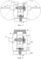
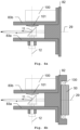
- Figures 4a and 4b show schematic depictions of different embodiments of the inside of a scanning module 10.
- the scanning module comprises a skeletal, three-part support 82,83a,83b, wherein the support here is formed by means of a skeletal structure consisting of three main parts, i.e. three support structures 82,83a,83b, which are coupled to each other, for example, by means of a mechanical connection based on normal pins.
- the three-part support has a support axis 29, also termed scanning module axis, and a central support structure 82. Two further separate support structures 83a,83b may be connected to the central support structure 82.
- the beam deflection element 11 is arranged exclusively on support structure 83a.
- the support axis 29 may coincide with the targeting unit rotation axis 21, or the support axis 29 may differ from the targeting unit rotation axis 21, e.g. in case the scanning module 10 and the targeting unit 30 are arranged at different heights on the construction 20a with respect to the base 20b.
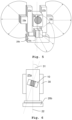
- FIG. 5 shows a schematic depiction of a fourth embodiment of a measuring device 20 according to the invention.
- the measuring device of Figure 5 comprises three scanning modules 10a,10b,10c. Scanning module 10a is arranged on the first column 27a and scanning module 10b is arranged on the second column 27b, while scanning module 10c is arranged below the targeting unit 30 and is laterally displaced to the targeting unit 30.
- Each of the three scanning modules 10a,10b,10c has a different field of view.
- the scanning module 10a arranged on the first column 27a faces in the opposite direction compared to the scanning module 10b arranged on the second column 27b.
- the third scanning module 10c has a larger field of view compared to scanning modules 10a,10b arranged on the columns 27a,27b since the columns 27a,27b do not limit the field of view of scanning module 10c.
- the field of view of scanning module 10c is substantially only limited by the targeting unit 30 and by the base 20b.
- a central line of scanning module 10c the central line located at an angular average of the field of view of scanning module 10c, is therefore not orthogonal to the pivoting axis 22.
- the central line instead points downwards on account of the fact that the field of view of scanning module 10c is more restricted by the targeting unit 30 than by the base 20b.
- Each scanning module 10a,10b,10c comprises a beam emitting region (shown hatched in Figure 5 ) through which an emitted scanning laser beam leaves the scanning module.
- the hatched surface may be embodied as an opaque surface covering the interior of the scanning module, e.g. depicted in Figure 4 , in which interior a beam deflection element is arranged.
- the opaque surface may be provided by a material which is transparent to a wavelength of the scanning laser beam, and not transparent to other wavelengths.
- Figure 6 shows a schematic depiction of a measuring device 20 according to the invention viewed from the side.
- a scanning module 10 is arranged on a first column 27a of the measuring device 20.
- a scan beam emission region of the scanning module 10 is graphically shown in Figure 6 in the center of the scanning module.
- the scanning module 10 is tilted 31 with respect to the pivoting axis 22, i.e. a scan plane of the scanning module 10 is inclined to the pivoting axis.
- the pivoting axis intersects the scan plane at one point.
- the scanning module 10 may e.g. be tilted 31 by 45 degree with respect to the pivoting axis 22.
- shaded surfaces may become visible in one of the multiple scan configurations without relocation of the total station.
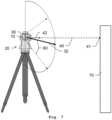
- FIG. 7 shows a schematic depiction of measuring device 20 according to the invention arranged on a tripod.
- the measuring device comprises a targeting unit 30 emitting a laser beam 40 and a scanning module 10.
- the laser beam 40 is emitted by the targeting unit 30 in a target direction 42 towards a target point 41 on an object 70 in order to measure a distance from the targeting unit 30 to the target point 41.
- the targeting unit 30 can be scanned up and down typically at a rate below 1Hz while the pivoting axis is continuously rotated in azimuthal direction. Such a scan, however, is slow, covers a small field of view of typically 20deg x 20deg, and takes several minutes.
- the scanning module 10 emits scanning laser beams 60 e.g. with high deflection speed of typically 100Hz.
- the scanning module 10 also has a field of view with a central line 32 in the field of view, which central line is substantially orthogonal to the targeting unit rotation axis 21 of the targeting unit 30.
- the total scanning range of the scanning module i.e. combined movement including rotation about the pivoting axis, may cover a full-dome horizontally 360deg and vertically from nadir to zenith.
- the measurement rate of the scanning module 10 is high e.g. at 100kPoints up to several Megapoints per second. So the measurement rate is at least 100 times faster than that of known total stations (respectively known scanning functionalities).
- the big benefit is that large field of view (FOV) scans can be scanned in a very short time. Even a full dome scan can be performed within one minute depending on the scan settings. Such high-speed scans are not feasible when using the targeting unit 30 for recording the point clouds.
- FOV field of view
- APDs fabricated from AlInAsSb digital alloys have several advantages over other long wavelength APDs as InGaAs/InP, for example its high sensitivity over a wide wavelength range from 800nm to 1600nm or a high gain in conjunction with a low excess noise.
- Antimony (Sb)-based III/V materials are capable of meeting the bandgap requirements for making APDs in the SWIR spectral range.
- Sb-based APDs have great characteristics with high quantum efficiency and single carrier multiplication to deliver high signal to noise ratios.
- the aforementioned receiver circuit comprising the AlInAsSb APD (or similar special-material APDs) may be used and applied not only for the measuring device according to the invention, but also for and within any other type of laser scanners, such as terrestrial-laser-scanners/reality-capture-scanners (see e.g. the following products of Leica Geosystems AG: "Leica RTC360", “Leica BLK2GO” or “Leica BLK360”) or aerial laser scanners.
Landscapes
- Engineering & Computer Science (AREA)
- Physics & Mathematics (AREA)
- General Physics & Mathematics (AREA)
- Radar, Positioning & Navigation (AREA)
- Remote Sensing (AREA)
- Computer Networks & Wireless Communication (AREA)
- Electromagnetism (AREA)
- Optical Radar Systems And Details Thereof (AREA)
- Length Measuring Devices By Optical Means (AREA)
Claims (15)
- Messvorrichtung (20), insbesondere Totalstation, Tachymeter, Theodolit oder Lasertracker, umfassend• eine Basis (20b),• eine Konstruktion (20a), die auf der Basis (20b) angeordnet ist und um eine Schwenkachse (22) geschwenkt oder gedreht werden kann, wobei die Konstruktion (20a) einen Hauptrahmen mit mindestens einer Säule (27a) aufweist,• eine Zieleinheit (30), die an dem Hauptrahmen befestigt ist, wobei die Zieleinheit (30) um eine Zieleinheit-Drehachse (21) geschwenkt oder gedreht werden kann, wobei die Zieleinheit (30) mindestens eine Emissionseinheit zum Emittieren eines ersten Laserstrahls aufweist, wobei die Emissionseinheit eine optische Zielachse definiert,• eine erste Winkelmessfunktion (24) zum Erfassen mindestens eines Schwenkwinkels, der durch eine relative Schwenkposition der Konstruktion (20a) in Bezug auf die Basis (20b) definiert ist,• ein Abtastmodul (10), umfassend∘ ein Strahlablenkungselement (11) zum Ablenken eines Abtastlaserstrahls (60), wobei das Strahlablenkungselement in motorisierter Form um eine Drehachse (12) gedreht werden kann, wobei sich die Drehachse (12) in einem empfangenen Zustand in einem definierten Winkel im Verhältnis zur Schwenkachse (22) befindet, und∘ eine zweite Winkelmessfunktion zum Bestimmen eines Drehwinkels aus einer Winkelposition des Strahlablenkungselements (11),wobei das Abtastmodul (10) ein Sichtfeld aufweist, das mindestens durch die Drehachse (12) und eine Orientierung des Strahlablenkungselements (11) in Bezug auf die Drehachse (12) definiert ist, wobei das Sichtfeld innerhalb einer Abtastfläche liegt, und wobei der abgelenkte Abtastlaserstrahl (60) im Sichtfeld liegt, sofern sich das Abtastmodul (10) innerhalb eines Winkeldrehbereichs des Sichtfelds um die Drehachse (12) befindet, wobei der Winkeldrehbereich des Sichtfelds einen zentralen Drehwinkel umfasst, und wobei das Strahlablenkungselement (11) im zentralen Drehwinkel dazu konfiguriert ist, den Abtastlaserstrahl (60) in einer zentralen Linienrichtung (32) abzulenken, die einem geometrischen Durchschnittswinkel im Winkeldrehbereich des Sichtfelds entspricht,• eine Steuer- und Verarbeitungseinheit zum Verarbeiten von Daten und zum Steuern der Messvorrichtung (20), insbesondere zum Steuern der Zieleinheit (30) und des Abtastmoduls (10),dadurch gekennzeichnet, dass
das Abtastmodul (10) derart auf dem Hauptrahmen und/oder auf der Zieleinheit (30) angeordnet ist, dass die zentrale Linienrichtung (32) um höchstens 45 Grad von der Orthogonalität in Bezug auf die Schwenkachse (22) abweicht. - Messvorrichtung (20) nach Anspruch 1, dadurch gekennzeichnet, dass das Abtastmodul (10) auf nicht lösbare Weise auf dem Hauptrahmen angeordnet ist.
- Messvorrichtung (20) nach einem der Ansprüche 1 bis 2, dadurch gekennzeichnet, dass das Abtastmodul (10) auf einer ersten Säule (27a) der mindestens einen Säule des Hauptrahmens angeordnet ist, und/oder das Abtastmodul (10c) unterhalb der Zieleinheit (30) angeordnet ist und/oder zur Zieleinheit (30) seitlich versetzt ist.
- Messvorrichtung (20) nach einem der Ansprüche 1 bis 3, dadurch gekennzeichnet, dass der Hauptrahmen mindestens zwei Säulen (27a, 27b) umfasst, und• auf der zweiten Säule (27b) ein weiteres Abtastmodul (10b), das eine weitere Drehachse aufweist, und ein weiteres Strahlablenkungselement angeordnet ist, und/oder• auf der zweiten Säule (27b) eine Kamera angeordnet ist.
- Messvorrichtung (20) nach einem der Ansprüche 1 bis 4, dadurch gekennzeichnet, dass ein Mittelpunkt des Abtastmoduls (10) und der Zieleinheit (30) in Bezug auf die Konstruktion (20a) im Wesentlichen auf der gleichen Höhe angeordnet sind.
- Messvorrichtung (20) nach Anspruch 5, dadurch gekennzeichnet, dass der Mittelpunkt in Bezug auf die Zieleinheit (30) seitlich versetzt ist.
- Messvorrichtung (20) nach einem der Ansprüche 1 bis 6, dadurch gekennzeichnet, dass das Sichtfeld in einer Abtastebene liegt und größer oder gleich 180 Grad ist, wobei das Abtastmodul (10) derart auf der Konstruktion (20b) und/oder auf der Zieleinheit (30) angeordnet ist, dass das Sichtfeld den Zenit der Messvorrichtung (20) umfasst.
- Messvorrichtung (20) nach einem der Ansprüche 1 bis 7, dadurch gekennzeichnet, dass die Abtastfläche als Abtastebene ausgebildet ist und die Schwenkachse (22) in der Abtastebene liegt.
- Messvorrichtung (20) nach einem der Ansprüche 1 bis 7, dadurch gekennzeichnet, dass die Abtastfläche als Abtastebene ausgebildet ist, und die Schwenkachse (22) parallel zur Abtastebene liegt und zur Abtastebene seitlich versetzt ist, und/oder die Schwenkachse (22) parallel zur weiteren Abtastebene liegt und zur weiteren Abtastebene seitlich versetzt ist.
- Messvorrichtung (20) nach einem der Ansprüche 1 bis 7, dadurch gekennzeichnet, dass die Abtastfläche als Abtastebene ausgebildet ist, und die Abtastebene in Bezug auf die Schwenkachse (22) geneigt (31) ist, und die Schwenkachse (22) an einem Schnittpunkt die Abtastebene schneidet und/oder die weitere Abtastebene in Bezug auf die Schwenkachse (22) geneigt ist, und die Schwenkachse (22) an einem weiteren Schnittpunkt die weitere Abtastebene schneidet.
- Messvorrichtung (20) nach einem der Ansprüche 1 bis 10, dadurch gekennzeichnet, dass die Steuer- und Verarbeitungseinheit dazu konfiguriert ist, den Betrieb des Abtastmoduls (10) und das Schwenken oder Drehen der Konstruktion (20a) um die Schwenkachse (22) zu synchronisieren.
- Messvorrichtung (20) nach einem der Ansprüche 1 bis 11, dadurch gekennzeichnet, dass das Strahlablenkungselement als Ablenkspiegel ausgebildet ist, wobei der Ablenkspiegel dazu konfiguriert ist, vollständig um die Drehachse (12) gedreht werden zu können, und/oder dass der Ablenkspiegel an nur einer Seite des Ablenkspiegels mechanisch an dem Abtastmodul (10) befestigt ist und/oder dass der Ablenkspiegel durch ein Gehäuse des Abtastmoduls (10) mechanisch vollständig abgeschirmt ist, wobei ein Teil des Gehäuses als eine undurchsichtige Abdeckung ausgebildet ist, die dazu konfiguriert ist, Licht mit einer Frequenz des Abtastlaserstrahls (60) durchzulassen.
- Messvorrichtung (20) nach einem der Ansprüche 1 bis 12, dadurch gekennzeichnet, dass die Zieleinheit (30) dazu konfiguriert ist, um die Zieleinheit-Drehachse (21) mit einer Drehfrequenz von höchstens 30 Hz, und insbesondere höchstens 10 Hz, gedreht zu werden.
- Messvorrichtung (20) nach einem der Ansprüche 1 bis 13, dadurch gekennzeichnet, dass die Steuer- und Verarbeitungseinheit dazu konfiguriert ist, die Konstruktion (20a) vollständig um die Schwenkachse (22) zu drehen.
- Messvorrichtung (20) nach einem der Ansprüche 1 bis 14, wobei die Zieleinheit-Drehebene durch die optische Zielachse erzeugt wird, wenn sich die Zieleinheit (30) um die Zieleinheit-Drehachse (21) dreht, wobei die Zieleinheit-Drehebene somit senkrecht zur Zieleinheit-Drehachse (21) liegt, dadurch gekennzeichnet, dass das Abtastmodul (10) derart auf der Konstruktion (20a) angeordnet ist, dass das Abtastmodul (10) nicht die Zieleinheit-Drehebene schneidet.
Priority Applications (3)
| Application Number | Priority Date | Filing Date | Title |
|---|---|---|---|
| EP21199258.1A EP4155664B1 (de) | 2021-09-27 | 2021-09-27 | Messvorrichtung mit einer zieleinheit und einem abtastmodul |
| CN202211155420.8A CN115876118A (zh) | 2021-09-27 | 2022-09-22 | 包括瞄准单元和扫描模块的测量装置 |
| US17/953,185 US20230096122A1 (en) | 2021-09-27 | 2022-09-26 | Measuring device comprising a targeting unit and a scanning module |
Applications Claiming Priority (1)
| Application Number | Priority Date | Filing Date | Title |
|---|---|---|---|
| EP21199258.1A EP4155664B1 (de) | 2021-09-27 | 2021-09-27 | Messvorrichtung mit einer zieleinheit und einem abtastmodul |
Publications (2)
| Publication Number | Publication Date |
|---|---|
| EP4155664A1 EP4155664A1 (de) | 2023-03-29 |
| EP4155664B1 true EP4155664B1 (de) | 2025-06-25 |
Family
ID=77998790
Family Applications (1)
| Application Number | Title | Priority Date | Filing Date |
|---|---|---|---|
| EP21199258.1A Active EP4155664B1 (de) | 2021-09-27 | 2021-09-27 | Messvorrichtung mit einer zieleinheit und einem abtastmodul |
Country Status (3)
| Country | Link |
|---|---|
| US (1) | US20230096122A1 (de) |
| EP (1) | EP4155664B1 (de) |
| CN (1) | CN115876118A (de) |
Family Cites Families (12)
| Publication number | Priority date | Publication date | Assignee | Title |
|---|---|---|---|---|
| DE19710722C2 (de) | 1996-03-15 | 2003-06-05 | Pentax Corp | Automatische Fokussiereinrichtung für ein Fernrohr |
| US5988862A (en) | 1996-04-24 | 1999-11-23 | Cyra Technologies, Inc. | Integrated system for quickly and accurately imaging and modeling three dimensional objects |
| JP3174551B2 (ja) | 1998-06-11 | 2001-06-11 | 旭光学工業株式会社 | 焦点調節レンズ位置検出装置 |
| JP3500077B2 (ja) | 1998-10-14 | 2004-02-23 | ペンタックス株式会社 | 視準望遠鏡の自動焦点調節機構 |
| CA2502012C (en) | 2002-10-12 | 2012-07-10 | Leica Geosystems Ag | Electronic display and control device for a measuring device |
| JP5469894B2 (ja) | 2008-07-05 | 2014-04-16 | 株式会社トプコン | 測量装置及び自動追尾方法 |
| EP2620745A1 (de) * | 2012-01-30 | 2013-07-31 | Hexagon Technology Center GmbH | Vermessungssystem mit einem Vermessungsgerät und einem Scanmodul |
| JP2013190272A (ja) * | 2012-03-13 | 2013-09-26 | Kyushu Univ | 3次元レーザ測量装置及び3次元レーザ測量方法 |
| JP6844959B2 (ja) * | 2016-06-17 | 2021-03-17 | 株式会社トプコン | 測量装置 |
| JP6857979B2 (ja) * | 2016-07-27 | 2021-04-14 | 株式会社トプコン | レーザスキャナの光学系及び測量装置 |
| JP2019090653A (ja) * | 2017-11-13 | 2019-06-13 | 株式会社トプコン | 測量装置、測量装置の校正確認方法および測量装置の校正確認用プログラム |
| JP7007167B2 (ja) * | 2017-12-05 | 2022-01-24 | 株式会社トプコン | 測量装置、測量装置の校正方法および測量装置の校正用プログラム |
-
2021
- 2021-09-27 EP EP21199258.1A patent/EP4155664B1/de active Active
-
2022
- 2022-09-22 CN CN202211155420.8A patent/CN115876118A/zh active Pending
- 2022-09-26 US US17/953,185 patent/US20230096122A1/en active Pending
Also Published As
| Publication number | Publication date |
|---|---|
| US20230096122A1 (en) | 2023-03-30 |
| CN115876118A (zh) | 2023-03-31 |
| EP4155664A1 (de) | 2023-03-29 |
Similar Documents
| Publication | Publication Date | Title |
|---|---|---|
| US9658059B2 (en) | Measuring device having a scanning functionality and a single-point measurement mode | |
| US11774557B2 (en) | Distance measurement instrument with scanning function | |
| US9658335B2 (en) | Measurement system with a measuring device and a scanning module | |
| US11933632B2 (en) | Surveying device with a coaxial beam deflection element | |
| CN1688867B (zh) | 测量仪器用的电子显示和控制装置 | |
| US10921430B2 (en) | Surveying system | |
| US20200141729A1 (en) | Target Instrument And Surveying System | |
| US6031606A (en) | Process and device for rapid detection of the position of a target marking | |
| US9891320B2 (en) | Measurement system with a measuring device and a scanning module | |
| US20200408520A1 (en) | Retroreflectors | |
| US10073165B2 (en) | Distance measurement instrument with scanning function | |
| JP7461185B2 (ja) | 測量装置及び測量装置システム | |
| RU2372628C1 (ru) | Многофункциональная оптико-локационная система | |
| EP4155664B1 (de) | Messvorrichtung mit einer zieleinheit und einem abtastmodul | |
| US11543244B2 (en) | Retroreflector comprising fisheye lens | |
| JP2024151569A (ja) | 測量装置 |
Legal Events
| Date | Code | Title | Description |
|---|---|---|---|
| PUAI | Public reference made under article 153(3) epc to a published international application that has entered the european phase |
Free format text: ORIGINAL CODE: 0009012 |
|
| STAA | Information on the status of an ep patent application or granted ep patent |
Free format text: STATUS: THE APPLICATION HAS BEEN PUBLISHED |
|
| AK | Designated contracting states |
Kind code of ref document: A1 Designated state(s): AL AT BE BG CH CY CZ DE DK EE ES FI FR GB GR HR HU IE IS IT LI LT LU LV MC MK MT NL NO PL PT RO RS SE SI SK SM TR |
|
| STAA | Information on the status of an ep patent application or granted ep patent |
Free format text: STATUS: REQUEST FOR EXAMINATION WAS MADE |
|
| 17P | Request for examination filed |
Effective date: 20230921 |
|
| RBV | Designated contracting states (corrected) |
Designated state(s): AL AT BE BG CH CY CZ DE DK EE ES FI FR GB GR HR HU IE IS IT LI LT LU LV MC MK MT NL NO PL PT RO RS SE SI SK SM TR |
|
| GRAP | Despatch of communication of intention to grant a patent |
Free format text: ORIGINAL CODE: EPIDOSNIGR1 |
|
| STAA | Information on the status of an ep patent application or granted ep patent |
Free format text: STATUS: GRANT OF PATENT IS INTENDED |
|
| INTG | Intention to grant announced |
Effective date: 20250120 |
|
| GRAS | Grant fee paid |
Free format text: ORIGINAL CODE: EPIDOSNIGR3 |
|
| GRAA | (expected) grant |
Free format text: ORIGINAL CODE: 0009210 |
|
| STAA | Information on the status of an ep patent application or granted ep patent |
Free format text: STATUS: THE PATENT HAS BEEN GRANTED |
|
| AK | Designated contracting states |
Kind code of ref document: B1 Designated state(s): AL AT BE BG CH CY CZ DE DK EE ES FI FR GB GR HR HU IE IS IT LI LT LU LV MC MK MT NL NO PL PT RO RS SE SI SK SM TR |
|
| REG | Reference to a national code |
Ref country code: GB Ref legal event code: FG4D |
|
| REG | Reference to a national code |
Ref country code: CH Ref legal event code: EP |
|
| REG | Reference to a national code |
Ref country code: CH Ref legal event code: EP |
|
| REG | Reference to a national code |
Ref country code: IE Ref legal event code: FG4D |
|
| REG | Reference to a national code |
Ref country code: DE Ref legal event code: R096 Ref document number: 602021032737 Country of ref document: DE |
|
| REG | Reference to a national code |
Ref country code: CH Ref legal event code: U11 Free format text: ST27 STATUS EVENT CODE: U-0-0-U10-U11 (AS PROVIDED BY THE NATIONAL OFFICE) Effective date: 20251001 |
|
| PG25 | Lapsed in a contracting state [announced via postgrant information from national office to epo] |
Ref country code: FI Free format text: LAPSE BECAUSE OF FAILURE TO SUBMIT A TRANSLATION OF THE DESCRIPTION OR TO PAY THE FEE WITHIN THE PRESCRIBED TIME-LIMIT Effective date: 20250625 |
|
| PGFP | Annual fee paid to national office [announced via postgrant information from national office to epo] |
Ref country code: DE Payment date: 20250919 Year of fee payment: 5 |
|
| REG | Reference to a national code |
Ref country code: LT Ref legal event code: MG9D |
|
| PG25 | Lapsed in a contracting state [announced via postgrant information from national office to epo] |
Ref country code: NO Free format text: LAPSE BECAUSE OF FAILURE TO SUBMIT A TRANSLATION OF THE DESCRIPTION OR TO PAY THE FEE WITHIN THE PRESCRIBED TIME-LIMIT Effective date: 20250925 Ref country code: GR Free format text: LAPSE BECAUSE OF FAILURE TO SUBMIT A TRANSLATION OF THE DESCRIPTION OR TO PAY THE FEE WITHIN THE PRESCRIBED TIME-LIMIT Effective date: 20250926 |
|
| PG25 | Lapsed in a contracting state [announced via postgrant information from national office to epo] |
Ref country code: BG Free format text: LAPSE BECAUSE OF FAILURE TO SUBMIT A TRANSLATION OF THE DESCRIPTION OR TO PAY THE FEE WITHIN THE PRESCRIBED TIME-LIMIT Effective date: 20250625 |
|
| PGFP | Annual fee paid to national office [announced via postgrant information from national office to epo] |
Ref country code: GB Payment date: 20250919 Year of fee payment: 5 |
|
| PG25 | Lapsed in a contracting state [announced via postgrant information from national office to epo] |
Ref country code: HR Free format text: LAPSE BECAUSE OF FAILURE TO SUBMIT A TRANSLATION OF THE DESCRIPTION OR TO PAY THE FEE WITHIN THE PRESCRIBED TIME-LIMIT Effective date: 20250625 |
|
| PGFP | Annual fee paid to national office [announced via postgrant information from national office to epo] |
Ref country code: FR Payment date: 20250922 Year of fee payment: 5 Ref country code: AT Payment date: 20251020 Year of fee payment: 5 |
|
| PG25 | Lapsed in a contracting state [announced via postgrant information from national office to epo] |
Ref country code: RS Free format text: LAPSE BECAUSE OF FAILURE TO SUBMIT A TRANSLATION OF THE DESCRIPTION OR TO PAY THE FEE WITHIN THE PRESCRIBED TIME-LIMIT Effective date: 20250925 |
|
| PG25 | Lapsed in a contracting state [announced via postgrant information from national office to epo] |
Ref country code: LV Free format text: LAPSE BECAUSE OF FAILURE TO SUBMIT A TRANSLATION OF THE DESCRIPTION OR TO PAY THE FEE WITHIN THE PRESCRIBED TIME-LIMIT Effective date: 20250625 |
|
| REG | Reference to a national code |
Ref country code: NL Ref legal event code: MP Effective date: 20250625 |
|
| PG25 | Lapsed in a contracting state [announced via postgrant information from national office to epo] |
Ref country code: NL Free format text: LAPSE BECAUSE OF FAILURE TO SUBMIT A TRANSLATION OF THE DESCRIPTION OR TO PAY THE FEE WITHIN THE PRESCRIBED TIME-LIMIT Effective date: 20250625 |