EP4155597A1 - Hydrogen pipe with double wall comprising at least one system for detecting leaks in at least one connection system, aircraft comprising at least one such pipe - Google Patents
Hydrogen pipe with double wall comprising at least one system for detecting leaks in at least one connection system, aircraft comprising at least one such pipe Download PDFInfo
- Publication number
- EP4155597A1 EP4155597A1 EP22194723.7A EP22194723A EP4155597A1 EP 4155597 A1 EP4155597 A1 EP 4155597A1 EP 22194723 A EP22194723 A EP 22194723A EP 4155597 A1 EP4155597 A1 EP 4155597A1
- Authority
- EP
- European Patent Office
- Prior art keywords
- upstream
- downstream
- crowns
- connection system
- pipe
- Prior art date
- Legal status (The legal status is an assumption and is not a legal conclusion. Google has not performed a legal analysis and makes no representation as to the accuracy of the status listed.)
- Pending
Links
Images

Classifications
-
- B—PERFORMING OPERATIONS; TRANSPORTING
- B64—AIRCRAFT; AVIATION; COSMONAUTICS
- B64D—EQUIPMENT FOR FITTING IN OR TO AIRCRAFT; FLIGHT SUITS; PARACHUTES; ARRANGEMENTS OR MOUNTING OF POWER PLANTS OR PROPULSION TRANSMISSIONS IN AIRCRAFT
- B64D37/00—Arrangements in connection with fuel supply for power plant
- B64D37/30—Fuel systems for specific fuels
-
- F—MECHANICAL ENGINEERING; LIGHTING; HEATING; WEAPONS; BLASTING
- F16—ENGINEERING ELEMENTS AND UNITS; GENERAL MEASURES FOR PRODUCING AND MAINTAINING EFFECTIVE FUNCTIONING OF MACHINES OR INSTALLATIONS; THERMAL INSULATION IN GENERAL
- F16L—PIPES; JOINTS OR FITTINGS FOR PIPES; SUPPORTS FOR PIPES, CABLES OR PROTECTIVE TUBING; MEANS FOR THERMAL INSULATION IN GENERAL
- F16L51/00—Expansion-compensation arrangements for pipe-lines
-
- B—PERFORMING OPERATIONS; TRANSPORTING
- B64—AIRCRAFT; AVIATION; COSMONAUTICS
- B64D—EQUIPMENT FOR FITTING IN OR TO AIRCRAFT; FLIGHT SUITS; PARACHUTES; ARRANGEMENTS OR MOUNTING OF POWER PLANTS OR PROPULSION TRANSMISSIONS IN AIRCRAFT
- B64D37/00—Arrangements in connection with fuel supply for power plant
- B64D37/005—Accessories not provided for in the groups B64D37/02 - B64D37/28
-
- B—PERFORMING OPERATIONS; TRANSPORTING
- B64—AIRCRAFT; AVIATION; COSMONAUTICS
- B64D—EQUIPMENT FOR FITTING IN OR TO AIRCRAFT; FLIGHT SUITS; PARACHUTES; ARRANGEMENTS OR MOUNTING OF POWER PLANTS OR PROPULSION TRANSMISSIONS IN AIRCRAFT
- B64D37/00—Arrangements in connection with fuel supply for power plant
- B64D37/32—Safety measures not otherwise provided for, e.g. preventing explosive conditions
-
- F—MECHANICAL ENGINEERING; LIGHTING; HEATING; WEAPONS; BLASTING
- F16—ENGINEERING ELEMENTS AND UNITS; GENERAL MEASURES FOR PRODUCING AND MAINTAINING EFFECTIVE FUNCTIONING OF MACHINES OR INSTALLATIONS; THERMAL INSULATION IN GENERAL
- F16J—PISTONS; CYLINDERS; SEALINGS
- F16J15/00—Sealings
- F16J15/02—Sealings between relatively-stationary surfaces
- F16J15/06—Sealings between relatively-stationary surfaces with solid packing compressed between sealing surfaces
- F16J15/08—Sealings between relatively-stationary surfaces with solid packing compressed between sealing surfaces with exclusively metal packing
- F16J15/0887—Sealings between relatively-stationary surfaces with solid packing compressed between sealing surfaces with exclusively metal packing the sealing effect being obtained by elastic deformation of the packing
-
- F—MECHANICAL ENGINEERING; LIGHTING; HEATING; WEAPONS; BLASTING
- F16—ENGINEERING ELEMENTS AND UNITS; GENERAL MEASURES FOR PRODUCING AND MAINTAINING EFFECTIVE FUNCTIONING OF MACHINES OR INSTALLATIONS; THERMAL INSULATION IN GENERAL
- F16J—PISTONS; CYLINDERS; SEALINGS
- F16J15/00—Sealings
- F16J15/02—Sealings between relatively-stationary surfaces
- F16J15/06—Sealings between relatively-stationary surfaces with solid packing compressed between sealing surfaces
- F16J15/10—Sealings between relatively-stationary surfaces with solid packing compressed between sealing surfaces with non-metallic packing
- F16J15/104—Sealings between relatively-stationary surfaces with solid packing compressed between sealing surfaces with non-metallic packing characterised by structure
- F16J15/106—Sealings between relatively-stationary surfaces with solid packing compressed between sealing surfaces with non-metallic packing characterised by structure homogeneous
-
- F—MECHANICAL ENGINEERING; LIGHTING; HEATING; WEAPONS; BLASTING
- F16—ENGINEERING ELEMENTS AND UNITS; GENERAL MEASURES FOR PRODUCING AND MAINTAINING EFFECTIVE FUNCTIONING OF MACHINES OR INSTALLATIONS; THERMAL INSULATION IN GENERAL
- F16J—PISTONS; CYLINDERS; SEALINGS
- F16J15/00—Sealings
- F16J15/46—Sealings with packing ring expanded or pressed into place by fluid pressure, e.g. inflatable packings
- F16J15/48—Sealings with packing ring expanded or pressed into place by fluid pressure, e.g. inflatable packings influenced by the pressure within the member to be sealed
-
- F—MECHANICAL ENGINEERING; LIGHTING; HEATING; WEAPONS; BLASTING
- F16—ENGINEERING ELEMENTS AND UNITS; GENERAL MEASURES FOR PRODUCING AND MAINTAINING EFFECTIVE FUNCTIONING OF MACHINES OR INSTALLATIONS; THERMAL INSULATION IN GENERAL
- F16L—PIPES; JOINTS OR FITTINGS FOR PIPES; SUPPORTS FOR PIPES, CABLES OR PROTECTIVE TUBING; MEANS FOR THERMAL INSULATION IN GENERAL
- F16L17/00—Joints with packing adapted to sealing by fluid pressure
- F16L17/02—Joints with packing adapted to sealing by fluid pressure with sealing rings arranged between outer surface of pipe and inner surface of sleeve or socket
- F16L17/03—Joints with packing adapted to sealing by fluid pressure with sealing rings arranged between outer surface of pipe and inner surface of sleeve or socket having annular axial lips
- F16L17/035—Joints with packing adapted to sealing by fluid pressure with sealing rings arranged between outer surface of pipe and inner surface of sleeve or socket having annular axial lips the sealing rings having two lips parallel to each other
-
- F—MECHANICAL ENGINEERING; LIGHTING; HEATING; WEAPONS; BLASTING
- F16—ENGINEERING ELEMENTS AND UNITS; GENERAL MEASURES FOR PRODUCING AND MAINTAINING EFFECTIVE FUNCTIONING OF MACHINES OR INSTALLATIONS; THERMAL INSULATION IN GENERAL
- F16L—PIPES; JOINTS OR FITTINGS FOR PIPES; SUPPORTS FOR PIPES, CABLES OR PROTECTIVE TUBING; MEANS FOR THERMAL INSULATION IN GENERAL
- F16L17/00—Joints with packing adapted to sealing by fluid pressure
- F16L17/06—Joints with packing adapted to sealing by fluid pressure with sealing rings arranged between the end surfaces of the pipes or flanges or arranged in recesses in the pipe ends or flanges
-
- F—MECHANICAL ENGINEERING; LIGHTING; HEATING; WEAPONS; BLASTING
- F16—ENGINEERING ELEMENTS AND UNITS; GENERAL MEASURES FOR PRODUCING AND MAINTAINING EFFECTIVE FUNCTIONING OF MACHINES OR INSTALLATIONS; THERMAL INSULATION IN GENERAL
- F16L—PIPES; JOINTS OR FITTINGS FOR PIPES; SUPPORTS FOR PIPES, CABLES OR PROTECTIVE TUBING; MEANS FOR THERMAL INSULATION IN GENERAL
- F16L39/00—Joints or fittings for double-walled or multi-channel pipes or pipe assemblies
- F16L39/005—Joints or fittings for double-walled or multi-channel pipes or pipe assemblies for concentric pipes
-
- F—MECHANICAL ENGINEERING; LIGHTING; HEATING; WEAPONS; BLASTING
- F16—ENGINEERING ELEMENTS AND UNITS; GENERAL MEASURES FOR PRODUCING AND MAINTAINING EFFECTIVE FUNCTIONING OF MACHINES OR INSTALLATIONS; THERMAL INSULATION IN GENERAL
- F16L—PIPES; JOINTS OR FITTINGS FOR PIPES; SUPPORTS FOR PIPES, CABLES OR PROTECTIVE TUBING; MEANS FOR THERMAL INSULATION IN GENERAL
- F16L51/00—Expansion-compensation arrangements for pipe-lines
- F16L51/02—Expansion-compensation arrangements for pipe-lines making use of bellows or an expansible folded or corrugated tube
- F16L51/025—Expansion-compensation arrangements for pipe-lines making use of bellows or an expansible folded or corrugated tube with several corrugations
-
- G—PHYSICS
- G01—MEASURING; TESTING
- G01M—TESTING STATIC OR DYNAMIC BALANCE OF MACHINES OR STRUCTURES; TESTING OF STRUCTURES OR APPARATUS, NOT OTHERWISE PROVIDED FOR
- G01M3/00—Investigating fluid-tightness of structures
- G01M3/02—Investigating fluid-tightness of structures by using fluid or vacuum
- G01M3/26—Investigating fluid-tightness of structures by using fluid or vacuum by measuring rate of loss or gain of fluid, e.g. by pressure-responsive devices, by flow detectors
- G01M3/28—Investigating fluid-tightness of structures by using fluid or vacuum by measuring rate of loss or gain of fluid, e.g. by pressure-responsive devices, by flow detectors for pipes, cables or tubes; for pipe joints or seals; for valves ; for welds
- G01M3/2807—Investigating fluid-tightness of structures by using fluid or vacuum by measuring rate of loss or gain of fluid, e.g. by pressure-responsive devices, by flow detectors for pipes, cables or tubes; for pipe joints or seals; for valves ; for welds for pipes
- G01M3/2815—Investigating fluid-tightness of structures by using fluid or vacuum by measuring rate of loss or gain of fluid, e.g. by pressure-responsive devices, by flow detectors for pipes, cables or tubes; for pipe joints or seals; for valves ; for welds for pipes using pressure measurements
-
- G—PHYSICS
- G01—MEASURING; TESTING
- G01M—TESTING STATIC OR DYNAMIC BALANCE OF MACHINES OR STRUCTURES; TESTING OF STRUCTURES OR APPARATUS, NOT OTHERWISE PROVIDED FOR
- G01M3/00—Investigating fluid-tightness of structures
- G01M3/02—Investigating fluid-tightness of structures by using fluid or vacuum
- G01M3/26—Investigating fluid-tightness of structures by using fluid or vacuum by measuring rate of loss or gain of fluid, e.g. by pressure-responsive devices, by flow detectors
- G01M3/28—Investigating fluid-tightness of structures by using fluid or vacuum by measuring rate of loss or gain of fluid, e.g. by pressure-responsive devices, by flow detectors for pipes, cables or tubes; for pipe joints or seals; for valves ; for welds
- G01M3/2807—Investigating fluid-tightness of structures by using fluid or vacuum by measuring rate of loss or gain of fluid, e.g. by pressure-responsive devices, by flow detectors for pipes, cables or tubes; for pipe joints or seals; for valves ; for welds for pipes
- G01M3/283—Investigating fluid-tightness of structures by using fluid or vacuum by measuring rate of loss or gain of fluid, e.g. by pressure-responsive devices, by flow detectors for pipes, cables or tubes; for pipe joints or seals; for valves ; for welds for pipes for double-walled pipes
-
- F—MECHANICAL ENGINEERING; LIGHTING; HEATING; WEAPONS; BLASTING
- F16—ENGINEERING ELEMENTS AND UNITS; GENERAL MEASURES FOR PRODUCING AND MAINTAINING EFFECTIVE FUNCTIONING OF MACHINES OR INSTALLATIONS; THERMAL INSULATION IN GENERAL
- F16L—PIPES; JOINTS OR FITTINGS FOR PIPES; SUPPORTS FOR PIPES, CABLES OR PROTECTIVE TUBING; MEANS FOR THERMAL INSULATION IN GENERAL
- F16L17/00—Joints with packing adapted to sealing by fluid pressure
- F16L17/06—Joints with packing adapted to sealing by fluid pressure with sealing rings arranged between the end surfaces of the pipes or flanges or arranged in recesses in the pipe ends or flanges
- F16L17/067—Plastics sealing rings
- F16L17/073—Plastics sealing rings the sealing rings having two lips parallel to each other
-
- F—MECHANICAL ENGINEERING; LIGHTING; HEATING; WEAPONS; BLASTING
- F16—ENGINEERING ELEMENTS AND UNITS; GENERAL MEASURES FOR PRODUCING AND MAINTAINING EFFECTIVE FUNCTIONING OF MACHINES OR INSTALLATIONS; THERMAL INSULATION IN GENERAL
- F16L—PIPES; JOINTS OR FITTINGS FOR PIPES; SUPPORTS FOR PIPES, CABLES OR PROTECTIVE TUBING; MEANS FOR THERMAL INSULATION IN GENERAL
- F16L2201/00—Special arrangements for pipe couplings
- F16L2201/30—Detecting leaks
-
- F—MECHANICAL ENGINEERING; LIGHTING; HEATING; WEAPONS; BLASTING
- F16—ENGINEERING ELEMENTS AND UNITS; GENERAL MEASURES FOR PRODUCING AND MAINTAINING EFFECTIVE FUNCTIONING OF MACHINES OR INSTALLATIONS; THERMAL INSULATION IN GENERAL
- F16L—PIPES; JOINTS OR FITTINGS FOR PIPES; SUPPORTS FOR PIPES, CABLES OR PROTECTIVE TUBING; MEANS FOR THERMAL INSULATION IN GENERAL
- F16L27/00—Adjustable joints, Joints allowing movement
- F16L27/12—Adjustable joints, Joints allowing movement allowing substantial longitudinal adjustment or movement
-
- Y—GENERAL TAGGING OF NEW TECHNOLOGICAL DEVELOPMENTS; GENERAL TAGGING OF CROSS-SECTIONAL TECHNOLOGIES SPANNING OVER SEVERAL SECTIONS OF THE IPC; TECHNICAL SUBJECTS COVERED BY FORMER USPC CROSS-REFERENCE ART COLLECTIONS [XRACs] AND DIGESTS
- Y02—TECHNOLOGIES OR APPLICATIONS FOR MITIGATION OR ADAPTATION AGAINST CLIMATE CHANGE
- Y02T—CLIMATE CHANGE MITIGATION TECHNOLOGIES RELATED TO TRANSPORTATION
- Y02T90/00—Enabling technologies or technologies with a potential or indirect contribution to GHG emissions mitigation
- Y02T90/40—Application of hydrogen technology to transportation, e.g. using fuel cells
Definitions
- the present application relates to a double-skinned hydrogen pipe comprising at least one leak detection system at the level of at least one connection system as well as to an aircraft comprising at least one such pipe.
- an aircraft operating on hydrogen comprises at least one hydrogen tank, hydrogen pipes connecting the hydrogen tank and hydrogen turbojets or fuel cells supplying electric motors. These hydrogen pipes must be configured to transport hydrogen in liquid form, at a temperature of the order of -270°C, and be perfectly sealed to avoid any contact between hydrogen and oxygen.
- the hydrogen is routed through double-skin pipes each comprising an outer conduit and an inner conduit positioned in the outer conduit, the space between the inner and outer conduits being evacuated to isolate the hydrogen channeled in the internal duct and the air located outside the external duct.
- the latter comprises a valve to stop the flow of hydrogen in the internal pipe as well as at least one pressure sensor configured to measure the pressure in the interspace.
- the pipes each comprise several sections placed end to end.
- the present invention aims to propose a solution to this problem.
- the subject of the invention is a pipeline comprising at least first and second sections as well as at least one connection system connecting the first and second sections, each of the first and second sections comprising an external conduit, an internal conduit positioned in the outer conduit as well as a space between the outer and inner conduits and containing a first atmosphere, the pipeline comprising at least one leak detection system configured to determine a characteristic of the first atmosphere, the connection system comprising at least one downstream ring connected to at least one of the outer and inner ducts of the first section, at least one upstream ring connected to at least outer and inner ducts of the second section as well as connecting elements connecting the upstream and downstream rings.
- the connection system comprises first and second annular seals inserted between the upstream and downstream crowns and configured to delimit with the upstream and downstream crowns a buffer space containing a second atmosphere
- the pipeline comprising a leak detection system configured to determine at least one characteristic of the second atmosphere
- the connection system including at least one stopper for holding the first and second seal rings apart, the first seal ring having an inside diameter, the second seal ring positioned inside of the first annular seal and having an outside diameter.
- the abutment is a circular rib secured to a first crown among the upstream and downstream crowns, the circular rib having an outer diameter substantially equal to the inner diameter of the first annular seal and an inner diameter substantially equal to the outer diameter of the second seal annular.
- connection system comprises at least one orifice passing through at least one of the upstream and downstream crowns to communicate the buffer space and one of the intermediate spaces of the first and second sections.
- connection system comprises at least one spacer inserted between the upstream and downstream crowns to keep them spaced apart.
- each spacer is a tube configured to house one of the connecting elements.
- first and second annular seals are sigma cross-section seals.
- connection system comprises, for at least one of the first and second sections, a first ring connected to the external conduit, a second ring connected to the internal conduit as well as a sealed connection connecting the first and second rings.
- the leaktight connection comprises at least one spacer inserted between the first and second rings to hold them apart, connecting elements connecting the first and second rings as well as an annular seal inserted between the first and second rings.
- At least one of the external and internal ducts of at least one of the first and second sections comprises a system for compensating for expansion phenomena.
- the invention also relates to an aircraft comprising at least one pipe according to one of the preceding characteristics.
- a pipe 10 is configured to channel a fluid 12 in a direction of flow 14.
- an aircraft comprises at least one such pipe 10 to channel hydrogen in the liquid state or in the gaseous state.
- a longitudinal direction is a direction parallel to the direction of flow 14.
- upstream and downstream refer to the direction of flow 14 of the fluid 12 in the pipe 10, the fluid flowing from the upstream to downstream.
- the pipe 10 comprises several sections, in particular first, second and third sections 16.1, 16.2, 16.3 positioned end to end, the first section 16.1 corresponding to an upstream section positioned upstream of the second section 16.2, the third section 16.3 corresponding to a section downstream positioned downstream of the second section 16.2.
- the first, second and third sections 16.1, 16.2, 16.3 are identical.
- the invention is not limited to this number of sections.
- the pipe 10 comprises at least two sections.
- Each section comprises an upstream end 18 and a downstream end 20.
- the upstream end 18 is connected to the downstream end of the upstream section by a first connection system 22 and the downstream end 20 is connected to the upstream end of the downstream section by a second connection system 24.
- the first and second connection systems 22, 24 are identical.
- Each section 16.1, 16.2, 16.3 comprises an external duct 26, an internal duct 28 configured to channel the fluid 12 and positioned inside the external duct 26.
- the external and internal ducts 26, 28 are cylindrical and have axes parallel to each other and to the longitudinal direction. According to one arrangement, the external and internal conduits 26 are coaxial.
- the section 16.2 comprises at least one spacer 30 maintaining the outer and inner ducts 26, 28 spaced apart over their entire circumference.
- the section 16.2 comprises two spacers 30 spaced apart in the longitudinal direction.
- Each spacer 30 comprises a crown which has an inside diameter substantially equal to the outside diameter of the internal duct 28 and an outside diameter substantially equal to the inside diameter of the external duct 26.
- the invention is not limited to this embodiment. concerning the spacer(s) 30.
- Each section 16.1, 16.2, 16.3 comprises an intermediate space 32 located between the external and internal ducts 26, 28 and containing an atmosphere.
- the pipe 10 comprises at least one leak detection system 34 configured to determine at least one characteristic of the atmosphere of the intermediate space 32.
- Each section 16.1, 16.2, 16.3 comprises at least one leak detection system 34. According to one application, this leak detection system 34 is used to control a fluid flow cut-off valve in line 10.
- the intermediate space 32 has a given vacuum level.
- the section 16.2 comprises a connector 36 configured to connect a vacuum device and extract the gas present in the intermediate space 32 in order to obtain the given vacuum level.
- the leak detection system 34 comprises at least one pressure sensor 38 configured to measure a pressure in the intermediate space 32.
- the intermediate space 32 contains an inerting gas at a given pressure.
- the section 16.2 comprises a connector 36 configured to connect a vacuum device in order to extract the gas present in the intermediate space 32 then a supply of inerting gas in order to fill the intermediate space 32 inert gas at a given pressure.
- the leak detection system 34 comprises a sensor for measuring an oxygen or hydrogen concentration in the intermediate space 32.
- At least one section 16.1, 16.2, 16.3 comprises an upstream crown 40 connecting the external and internal ducts 26, 28 at the upstream end 18 as well as a downstream crown 42 connecting the external and internal ducts 26, 28 at of the downstream end 20.
- the upstream and downstream rings 40, 42 are identical and each take the form of a plate positioned in a plane approximately perpendicular to the longitudinal direction.
- Each upstream or downstream ring 40, 42 has an inside diameter substantially equal to the inside diameter of the internal duct 28 and an outside diameter greater than the outside diameter of the external duct 26.
- the upstream and downstream rings 40, 42 are connected to the external and internal ducts 26 , 28 sealed.
- Each of the upstream and downstream rings 40, 42 has a peripheral zone 40.1, 42.1 which extends beyond the external conduit 26.
- the first connection system 22 comprises first through holes 22.1 positioned in the peripheral zone 40.1 of the crown upstream 40 of the section 16.2 in question as well as second through-holes 22.2 positioned in the peripheral zone 42.1 of the downstream ring 42 of the upstream section 16.1, each of the first through-holes 22.1 being positioned in line with a second through-hole 22.2.
- the first connection system 22 comprises first connecting elements 22.3 connecting the upstream and downstream crowns 40, 42, housed in the first and second through-holes 22.1, 22.2.
- the second connection system 24 comprises first through-holes 24.1 positioned in the peripheral zone 42.1 of the downstream ring 42 of the section in question 16.2 as well as second through-holes 24.2 positioned in the peripheral zone 40.1 of the upstream ring 40 of the section downstream 16.3, each of the first through holes 24.1 being positioned in line with a second through hole 24.2.
- the second connection system 24 comprises second connecting elements 24.3, connecting the upstream and downstream crowns 40, 42, housed in the first and second through holes 24.1, 24.2.
- connection system 24 comprises a first downstream ring 42 (or upstream) connected to the outer conduit 26, a second downstream ring 42' (or upstream) connected to the inner conduit 28 as well as a sealed connection 44 connecting the first and second downstream rings 42, 42' (or upstream).
- first and second downstream rings 42, 42' are pressed against each other over their entire circumference and held pressed by connecting elements.
- the sealed connection 44 comprises at least one spacer 44.1 interposed between the first and second downstream rings 42, 42' (or upstream) in order to keep them spaced apart in the longitudinal direction over their entire circumference, connecting elements connecting the first and second downstream crowns 42, 42' (or upstream) as well as an annular seal 44.2 inserted between the first and second downstream crowns 42, 42' (or upstream).
- the connecting elements of the sealed connection 44 are those of the connection system 24.
- the sealed connection 44 comprises several spacers 44.1 distributed over the circumference of the first and second downstream rings 42, 42' (or upstream) . Each spacer 44.1 is in the form of a tube through which one of the connecting elements passes.
- the sealed connection 44 may include a spacer 44.1 for each connecting element.
- the annular seal 44.2 has an internal diameter substantially equal to the external diameter of the external conduit 26.
- the sealed connection 44 comprises at least one abutment 44.3, secured to one of the first and second downstream rings 42, 42' (or upstream), configured according to the pressure difference between the exterior of the outer conduit 26 and the intermediate space 32.
- the pressure outside the outer conduit 26 being significantly higher than that inside the intermediate space 32, the stop 44.3 is tubular, connected to the first downstream crown 42, positioned in the extension of the outer duct 26 and inside the annular seal 44.2.
- the annular seal 44.2 is a seal with a cross-section in sigma ⁇ , oriented so that the pressure difference on either side of the annular seal 44.2 reinforces the seal.
- connection system 22, 24 comprises at least one downstream ring 42 connected to at least one of the external and internal ducts 26, 28 of a first section, at least one upstream ring 40 connected to at least external and internal ducts 26, 28 of a second section as well as connecting elements 22.3, 24.3 connecting the upstream and downstream ring 40, 42.
- the internal duct 28 comprises a first part 28.1 which extends from the upstream crown 40 to a first end 28.1E as well as a second part 28.2 which extends from the downstream crown 42 to a second end 28.2 E, the first and second ends 28.1E, 28.2E being configured to slide one inside the other.
- the first end 28.1E slides in the second end 28.2E which has an enlarged cross section.
- the internal duct 28 has at least one annular seal 46 inserted between the first and second ends 28.1E, 28.2E, positioned in the zone of overlap of the first and second ends 28.1E, 28.2E.
- the internal duct 28 comprises at least one abutment 48 to hold the annular seal 46 in place between the first and second ends 28.1E, 28.2E, configured according to the pressure difference between the interior of the internal duct 28 and the intermediate space 32.
- the pressure inside the internal duct 28 being significantly higher than that inside the intermediate space 32, the abutment 48 comprises a rim 48.1 connected to the second part 28.2 of the internal duct 28 and positioned at the second end 28.2E.
- the annular seal 46 is a seal of cross section in sigma ⁇ , oriented so that the pressure difference on either side of the annular seal 46 reinforces the seal.
- the internal duct 28 comprises a part 28.1 which extends from the upstream crown 40 to a first end 28.1E, a second part 28.2 which extends from the downstream crown 42 to a second end 28.2E as well as 'a bellows 28.3 connecting the first and second parts 28.1, 28.2 and more particularly their first and second ends 28.1E, 28.2E.
- the outer duct 26 may comprise first and second parts 26.1, 26.2 as well as a bellows 26.3 connecting the first and second parts 26.1, 26.2.
- At least one of the external and internal ducts of at least one section comprising a system for compensating for expansion phenomena in the longitudinal direction.
- At least one connection system 22, 24 comprises at least one spacer 50 inserted between the upstream and downstream rings 40, 42 to keep them spaced apart and create a buffer space 52 between the upstream and downstream rings 40 , 42.
- connection system 22, 24 comprises several spacers 50 distributed over the entire circumference of the upstream and downstream crowns 40, 42.
- Each spacer 50 is a tube configured to house one of the connecting elements 22.3, 24.3.
- the connection system 22, 24 comprises as many spacers 50 as connecting elements 22.3, 24.3.
- the spacers 50 all have the same length (dimension taken in the longitudinal direction)
- the connection system 22, 24 comprises first and second annular seals 54, 56, inserted between the upstream and downstream crowns 40, 42, positioned so as to isolate the buffer space 52 from the inside of the internal conduit 28 and from the exterior of the external duct 26.
- the first annular seal 54 is positioned in the extension of the external ducts 26 and the second annular seal 56 is positioned inside the first annular seal 54, in the extension of the internal ducts 28
- the first and second annular joints 54, 56 are joints of cross-section in sigma ⁇ , oriented so that the pressure difference on either side of the annular joints 54, 56 reinforces the tightness.
- the first and second annular joints 54, 56 delimit with the upstream and downstream crowns 40, 42 a buffer space 52 which makes it possible to detect a possible leak at the level of the connection system 22, 24.
- the connection system 22, 24 may not include a spacer 50 if the first and second annular seals are configured to perform the function of spacer 50.
- each connection system 22, 24 comprises at least one spacer 50 to hold the upstream and downstream crowns 40, 42 spaced apart as well as first and second annular seals 54, 56 delimiting with the upstream and downstream crowns 40, 42 a buffer space 52 containing an atmosphere.
- connection system 22, 24 comprises at least one abutment 58 to hold apart the first and second annular seals 54, 56.
- This (or these) abutment(s) 58 is (are) configured according to the difference in pressure between on the one hand the buffer space 52 and on the other hand the interior of the internal duct 28 and the exterior of the external duct 26.
- connection system 22, 24 comprises a stop 58, inserted between the first and second annular seals 54, 56, preventing the approximation of the latter.
- the stop 58 is a circular rib secured to the upstream crown 40 which has an outer diameter substantially equal to the inner diameter of the first annular seal 54 and an inner diameter substantially equal to the outer diameter of the second annular seal 56.
- the invention is not limited to this embodiment for the stop(s) 58. The latter could be integral with the downstream crown 42.
- At least one of the stops 58 has a dimension, in a longitudinal direction, less than the length of the spacers 58.
- Line 10 includes at least one leak detection system configured to determine at least one characteristic of the atmosphere in buffer space 52.
- the buffer space 52 has a given vacuum level.
- the leak detection system comprises at least one pressure sensor for measuring the pressure in the buffer space 52 in order to detect a leak.
- the buffer space 52 contains an inerting gas at a given pressure.
- the leak detection system of the connection system 22, 24 includes at least one sensor configured to detect a concentration of hydrogen or oxygen in the buffer space 52 in order to detect a leak.
- connection system 22, 24 comprises at least one orifice 60 passing through the upstream or downstream ring 40, 42 to communicate the buffer space 52 with one of the intermediate spaces 32 of the upstream and downstream sections .
- the buffer space 52 and the intermediate space 32 have the same atmosphere, the same pressure and a single leak detection system 34, such as a pressure sensor 38 making it possible to detect a leak in the intermediate and buffer spaces 32, 52.
- connection system 22, 24 comprises several orifices 60 distributed over the circumference of the upstream or downstream crown 40, 42.
- the fact of providing several orifices improves the detection of a leak in the buffer space 52 by a leak detection system positioned at the intermediate space 32.
- These orifices 60 are regularly distributed over the entire circumference of the upstream or downstream crown 40, 42.
- the orifices 60 are provided on the upstream crown 40 of the downstream section. However, they could be positioned on the downstream crown 42 of the upstream section.
- the abutment 58 is secured to a first crown among the upstream and downstream crowns 40, 42 and the orifice(s) is (or are) positioned on a second crown among the upstream crowns and downstream 40, 42 different from the first crown.
Abstract
L'invention a pour objet une canalisation comprenant :- au moins des premier et deuxième tronçons (16.1, 16.2) comportant chacun des conduits externe et interne (26, 28),- au moins un système de raccordement (22) reliant les premier et deuxième tronçons (16.1, 16.2) et comportant :∘ au moins une couronne aval (42) reliée à au moins un des conduits externe et interne (26, 28) du premier tronçon (16.1),∘ au moins une couronne amont (40) reliée à au moins des conduits externe et interne (26, 28) du deuxième tronçon (16.2),∘ des éléments de liaison reliant les couronnes amont et aval (40, 42),∘ des premier et deuxième joints annulaires, intercalés entre les couronnes amont et aval (40, 42), configurés pour délimiter avec les couronnes amont et aval (40, 42) un espace tampon contenant une atmosphère, la canalisation comprenant au moins un système de détection de fuite configuré pour déterminer au moins une caractéristique de l'atmosphère de l'espace tampon.The subject of the invention is a pipeline comprising:- at least first and second sections (16.1, 16.2) each comprising external and internal ducts (26, 28),- at least one connection system (22) connecting the first and second sections (16.1, 16.2) and comprising:∘ at least one downstream crown (42) connected to at least one of the external and internal ducts (26, 28) of the first section (16.1),∘ at least one upstream crown (40) connected to at least external and internal ducts (26, 28) of the second section (16.2),∘ connecting elements connecting the upstream and downstream crowns (40, 42),∘ first and second annular seals, inserted between the crowns upstream and downstream (40, 42), configured to delimit with the upstream and downstream crowns (40, 42) a buffer space containing an atmosphere, the pipeline comprising at least one leak detection system configured to determine at least one characteristic of the atmosphere of the buffer space.
Description
La présente demande se rapporte à une canalisation d'hydrogène à double peau comprenant au moins un système de détection de fuite au niveau d'au moins un système de raccordement ainsi qu'à un aéronef comprenant au moins une telle canalisation.The present application relates to a double-skinned hydrogen pipe comprising at least one leak detection system at the level of at least one connection system as well as to an aircraft comprising at least one such pipe.
Selon un mode de réalisation, un aéronef fonctionnant à l'hydrogène comprend au moins un réservoir d'hydrogène, des canalisations d'hydrogène reliant le réservoir d'hydrogène et des turboréacteurs à hydrogène ou des piles à combustible alimentant des moteurs électriques. Ces canalisations d'hydrogène doivent être configurées pour acheminer l'hydrogène sous forme liquide, à une température de l'ordre de -270°C, et être parfaitement étanches pour éviter tout contact entre l'hydrogène et l'oxygène.According to one embodiment, an aircraft operating on hydrogen comprises at least one hydrogen tank, hydrogen pipes connecting the hydrogen tank and hydrogen turbojets or fuel cells supplying electric motors. These hydrogen pipes must be configured to transport hydrogen in liquid form, at a temperature of the order of -270°C, and be perfectly sealed to avoid any contact between hydrogen and oxygen.
Selon un mode de réalisation, l'hydrogène est acheminé dans des canalisations à double peau comprenant chacune un conduit externe et un conduit interne positionné dans le conduit externe, l'espace intercalaire entre les conduits interne et externe étant mis au vide pour isoler l'hydrogène canalisé dans le conduit interne et l'air situé à l'extérieur du conduit externe. Pour stopper l'écoulement de l'hydrogène en cas de fuite et obtenir une canalisation sûre, cette dernière comprend une vanne pour stopper l'écoulement de l'hydrogène dans le conduit interne ainsi qu'au moins un capteur de pression configuré pour mesurer la pression dans l'espace intercalaire. Ainsi, lorsque le capteur de pression détecte une augmentation de pression dans la zone intercalaire, correspondant à une probable fuite d'hydrogène ou d'oxygène, la vanne est commutée à l'état fermé.According to one embodiment, the hydrogen is routed through double-skin pipes each comprising an outer conduit and an inner conduit positioned in the outer conduit, the space between the inner and outer conduits being evacuated to isolate the hydrogen channeled in the internal duct and the air located outside the external duct. To stop the flow of hydrogen in the event of a leak and obtain a safe pipeline, the latter comprises a valve to stop the flow of hydrogen in the internal pipe as well as at least one pressure sensor configured to measure the pressure in the interspace. Thus, when the pressure sensor detects an increase in pressure in the intermediate zone, corresponding to a probable leak of hydrogen or oxygen, the valve is switched to the closed state.
Compte tenu de la distance entre le réservoir et les turboréacteurs ou les piles à combustible, les canalisations comprennent chacune plusieurs tronçons mis bout à bout.Given the distance between the tank and the turbojets or the fuel cells, the pipes each comprise several sections placed end to end.
L'obtention d'une canalisation sûre sur toute sa longueur, et plus particulièrement dans les zones de raccordement des tronçons, s'avère problématique.Obtaining a safe pipeline over its entire length, and more particularly in the connection areas of the sections, proves to be problematic.
La présente invention vise à proposer une solution à cette problématique.The present invention aims to propose a solution to this problem.
A cet effet, l'invention a pour objet une canalisation comprenant au moins des premier et deuxième tronçons ainsi qu'au moins un système de raccordement reliant les premier et deuxième tronçons, chacun des premier et deuxième tronçons comportant un conduit externe, un conduit interne positionné dans le conduit externe ainsi qu'un espace intercalaire situé entre les conduits externe et interne et contenant une première atmosphère, la canalisation comprenant au moins un système de détection de fuite configuré pour déterminer une caractéristique de la première atmosphère, le système de raccordement comprenant au moins une couronne aval reliée à au moins un des conduits externe et interne du premier tronçon, au moins une couronne amont reliée à au moins des conduits externe et interne du deuxième tronçon ainsi que des éléments de liaison reliant les couronnes amont et aval.To this end, the subject of the invention is a pipeline comprising at least first and second sections as well as at least one connection system connecting the first and second sections, each of the first and second sections comprising an external conduit, an internal conduit positioned in the outer conduit as well as a space between the outer and inner conduits and containing a first atmosphere, the pipeline comprising at least one leak detection system configured to determine a characteristic of the first atmosphere, the connection system comprising at least one downstream ring connected to at least one of the outer and inner ducts of the first section, at least one upstream ring connected to at least outer and inner ducts of the second section as well as connecting elements connecting the upstream and downstream rings.
Selon l'invention, le système de raccordement comprend des premier et deuxième joints annulaires intercalés entre les couronnes amont et aval et configurés pour délimiter avec les couronnes amont et aval un espace tampon contenant une deuxième atmosphère, la canalisation comprenant un système de détection de fuite configuré pour déterminer au moins une caractéristique de la deuxième atmosphère, le système de raccordement comprenant au moins une butée pour maintenir les premier et deuxième joints annulaires écartés, le premier joint annulaire présentant un diamètre intérieur, le deuxième joint annulaire étant positionné à l'intérieur du premier joint annulaire et présentant un diamètre extérieur. En complément, la butée est une nervure circulaire solidaire d'une première couronne parmi les couronnes amont et aval, la nervure circulaire présentant un diamètre extérieur sensiblement égal au diamètre intérieur du premier joint annulaire et un diamètre intérieur sensiblement égal au diamètre extérieur du deuxième joint annulaire.According to the invention, the connection system comprises first and second annular seals inserted between the upstream and downstream crowns and configured to delimit with the upstream and downstream crowns a buffer space containing a second atmosphere, the pipeline comprising a leak detection system configured to determine at least one characteristic of the second atmosphere, the connection system including at least one stopper for holding the first and second seal rings apart, the first seal ring having an inside diameter, the second seal ring positioned inside of the first annular seal and having an outside diameter. In addition, the abutment is a circular rib secured to a first crown among the upstream and downstream crowns, the circular rib having an outer diameter substantially equal to the inner diameter of the first annular seal and an inner diameter substantially equal to the outer diameter of the second seal annular.
Cette solution permet de pouvoir détecter une éventuelle fuite au niveau du système de raccordement et de rendre plus sûre la canalisation.This solution makes it possible to detect a possible leak at the level of the connection system and to make the pipeline safer.
Selon une autre caractéristique, le système de raccordement comprend au moins un orifice traversant au moins une des couronnes amont et aval pour faire communiquer l'espace tampon et l'un des espaces intercalaires des premier et deuxième tronçons.According to another characteristic, the connection system comprises at least one orifice passing through at least one of the upstream and downstream crowns to communicate the buffer space and one of the intermediate spaces of the first and second sections.
Selon une autre caractéristique, le système de raccordement comprend au moins une entretoise intercalée entre les couronnes amont et aval pour les maintenir espacées.According to another characteristic, the connection system comprises at least one spacer inserted between the upstream and downstream crowns to keep them spaced apart.
Selon une autre caractéristique, chaque entretoise est un tube configuré pour loger un des éléments de liaison.According to another characteristic, each spacer is a tube configured to house one of the connecting elements.
Selon une autre caractéristique, les premier et deuxième joints annulaires sont des joints de section transversale en sigma.According to another feature, the first and second annular seals are sigma cross-section seals.
Selon une autre caractéristique, le système de raccordement comprend, pour au moins un des premier et deuxième tronçons, une première couronne reliée au conduit externe, une deuxième couronne reliée au conduit interne ainsi qu'une liaison étanche reliant les première et deuxième couronnes.According to another characteristic, the connection system comprises, for at least one of the first and second sections, a first ring connected to the external conduit, a second ring connected to the internal conduit as well as a sealed connection connecting the first and second rings.
Selon une autre caractéristique, la liaison étanche comprend au moins une entretoise intercalée entre les première et deuxième couronnes pour les maintenir écartées, des éléments de liaison reliant les première et deuxième couronnes ainsi qu'un joint annulaire intercalé entre les première et deuxième couronnes.According to another characteristic, the leaktight connection comprises at least one spacer inserted between the first and second rings to hold them apart, connecting elements connecting the first and second rings as well as an annular seal inserted between the first and second rings.
Selon une autre caractéristique, au moins un des conduits externe et interne d'au moins un des premier et deuxième tronçons comprend un système de compensation des phénomènes de dilatation.According to another characteristic, at least one of the external and internal ducts of at least one of the first and second sections comprises a system for compensating for expansion phenomena.
L'invention a également pour objet un aéronef comprenant au moins une canalisation selon l'une des caractéristiques précédentes.The invention also relates to an aircraft comprising at least one pipe according to one of the preceding characteristics.
D'autres caractéristiques et avantages ressortiront de la description de l'invention qui va suivre, description donnée à titre d'exemple uniquement, en regard des dessins annexés parmi lesquels :
- La
figure 1 est une coupe longitudinale d'une canalisation illustrant un premier mode de réalisation de l'invention, - La
figure 2 est une coupe illustrant en détail une zone II de lafigure 1 , - La
figure 3 est une coupe illustrant en détail une zone III de lafigure 1 , - La
figure 4 est une coupe illustrant en détail une zone IV de lafigure 1 , - La
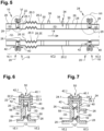
figure 5 est une coupe longitudinale d'une canalisation illustrant un deuxième mode de réalisation, - La
figure 6 est une coupe illustrant en détail une zone VI de lafigure 5 , et - La
figure 7 est une coupe illustrant en détail une zone VII de lafigure 5 .
- There
figure 1 is a longitudinal section of a pipe illustrating a first embodiment of the invention, - There
figure 2 is a section illustrating in detail a zone II of thefigure 1 , - There
picture 3 is a section illustrating in detail a zone III of thefigure 1 , - There
figure 4 is a section illustrating in detail a zone IV of thefigure 1 , - There
figure 5 is a longitudinal section of a pipe illustrating a second embodiment, - There
figure 6 is a section illustrating in detail a zone VI of thefigure 5 , And - There
figure 7 is a section illustrating in detail a zone VII of thefigure 5 .
Selon les premier et deuxième modes de réalisation visibles sur les
Pour la suite de la description, une direction longitudinale est une direction parallèle au sens d'écoulement 14. Les termes amont et aval font référence au sens d'écoulement 14 du fluide 12 dans la canalisation 10, le fluide s'écoulant de l'amont vers l'aval.For the rest of the description, a longitudinal direction is a direction parallel to the direction of
La canalisation 10 comprend plusieurs tronçons, notamment des premier, deuxième et troisième tronçons 16.1, 16.2, 16.3 positionnés bout à bout, le premier tronçon 16.1 correspondant à un tronçon amont positionné en amont du deuxième tronçon 16.2, le troisième tronçon 16.3 correspondant à un tronçon aval positionné en aval du deuxième tronçon 16.2.The
Selon une configuration, les premier, deuxième et troisième tronçons 16.1, 16.2, 16.3 sont identiques.According to one configuration, the first, second and third sections 16.1, 16.2, 16.3 are identical.
Bien entendu, l'invention n'est pas limitée à ce nombre de tronçons. Quel que soit le mode de réalisation, la canalisation 10 comprend au moins deux tronçons.Of course, the invention is not limited to this number of sections. Whatever the embodiment, the
Chaque tronçon comprend une extrémité amont 18 et une extrémité aval 20. Pour chaque tronçon 16.1, 16.2, 16.3, l'extrémité amont 18 est reliée à l'extrémité aval du tronçon amont par un premier système de raccordement 22 et l'extrémité aval 20 est reliée à l'extrémité amont du tronçon aval par un deuxième système de raccordement 24. Selon une configuration, les premier et deuxième systèmes de raccordement 22, 24 sont identiques. Chaque tronçon 16.1, 16.2, 16.3 comprend un conduit externe 26, un conduit interne 28 configuré pour canaliser le fluide 12 et positionné à l'intérieur du conduit externe 26.Each section comprises an
Selon un mode de réalisation, les conduits externe et interne 26, 28 sont cylindriques et présentent des axes parallèles entre eux et à la direction longitudinale. Selon un agencement, les conduits externe et interne 26 sont coaxiaux.According to one embodiment, the external and
Selon une configuration visible sur la
La canalisation 10 comprend au moins un système de détection de fuite 34 configuré pour déterminer au moins une caractéristique de l'atmosphère de l'espace intercalaire 32. Chaque tronçon 16.1, 16.2, 16.3 comprend au moins un système de détection de fuite 34. Selon une application, ce système de détection de fuite 34 est utilisé pour commander une vanne de coupure de l'écoulement de fluide dans la canalisation 10.The
Selon une première configuration, l'espace intercalaire 32 présente un niveau de vide donné. Selon cette première configuration, le tronçon 16.2 comprend un raccord 36 configuré pour raccorder un appareil de mise au vide et extraire le gaz présent dans l'espace intercalaire 32 afin d'obtenir le niveau de vide donné. En complément, le système de détection de fuite 34 comprend au moins un capteur de pression 38 configuré pour mesurer une pression dans l'espace intercalaire 32.According to a first configuration, the
Selon une deuxième configuration, l'espace intercalaire 32 contient un gaz d'inertage à une pression donnée. Selon cette deuxième configuration, le tronçon 16.2 comprend un raccord 36 configuré pour raccorder un appareil de mise au vide afin d'extraire le gaz présent dans l'espace intercalaire 32 puis une alimentation en gaz d'inertage afin de remplir l'espace intercalaire 32 en gaz d'inertage à une pression donnée. En complément, le système de détection de fuite 34 comprend un capteur de mesure d'une concentration d'oxygène ou d'hydrogène dans l'espace intercalaire 32.According to a second configuration, the
Selon une première configuration visible notamment sur les
Chacune des couronnes amont et aval 40, 42 présente une zone périphérique 40.1, 42.1 qui s'étend au-delà du conduit externe 26.Each of the upstream and
Pour un tronçon considéré 16.2, le premier système de raccordement 22 comprend des premiers orifices traversants 22.1 positionnés dans la zone périphérique 40.1 de la couronne amont 40 du tronçon considéré 16.2 ainsi que des deuxièmes orifices traversants 22.2 positionnés dans la zone périphérique 42.1 de la couronne aval 42 du tronçon amont 16.1, chacun des premiers orifices traversants 22.1 étant positionné au droit d'un deuxième orifice traversant 22.2. En complément, le premier système de raccordement 22 comprend des premiers éléments de liaison 22.3 reliant les couronnes amont et aval 40, 42, logés dans les premiers et deuxièmes orifices traversants 22.1, 22.2. En parallèle, le deuxième système de raccordement 24 comprend des premiers orifices traversants 24.1 positionnés dans la zone périphérique 42.1 de la couronne aval 42 du tronçon considéré 16.2 ainsi que des deuxièmes orifices traversants 24.2 positionnés dans la zone périphérique 40.1 de la couronne amont 40 du tronçon aval 16.3, chacun des premiers orifices traversants 24.1 étant positionné au droit d'un deuxième orifice traversant 24.2. En complément, le deuxième système de raccordement 24 comprend des deuxièmes éléments de liaison 24.3, reliant les couronnes amont et aval 40, 42, logés dans les premiers et deuxièmes orifices traversants 24.1, 24.2.For a considered section 16.2, the
Selon une deuxième configuration visible notamment sur la
Selon un agencement, le joint annulaire 44.2 présente un diamètre intérieur sensiblement égal au diamètre extérieur du conduit externe 26.According to one arrangement, the annular seal 44.2 has an internal diameter substantially equal to the external diameter of the
Pour maintenir en place le joint annulaire 44.2, la liaison étanche 44 comprend au moins une butée 44.3, solidaire d'une des première et deuxième couronnes aval 42, 42' (ou amont), configurée en fonction de la différence de pression entre l'extérieur du conduit externe 26 et l'espace intercalaire 32. La pression à l'extérieur du conduit externe 26 étant nettement supérieure à celle à l'intérieur de l'espace intercalaire 32, la butée 44.3 est tubulaire, reliée à la première couronne aval 42, positionnée dans le prolongement du conduit externe 26 et à l'intérieur du joint annulaire 44.2. A titre d'exemple, le joint annulaire 44.2 est un joint de section transversale en sigma Σ, orienté de manière à ce que la différence de pression de part et d'autre du joint annulaire 44.2 renforce l'étanchéité.To hold the annular seal 44.2 in place, the sealed
L'invention n'est pas limitée à ces modes de réalisation pour les extrémités des tronçons et les systèmes de raccordement 22, 24. Quel que soit le mode de réalisation, un système de raccordement 22, 24 comprend au moins une couronne aval 42 reliée à au moins un des conduits externe et interne 26, 28 d'un premier tronçon, au moins une couronne amont 40 reliée à au moins des conduits externe et interne 26, 28 d'un deuxième tronçon ainsi que des éléments de liaison 22.3, 24.3 reliant les couronne amont et aval 40, 42.The invention is not limited to these embodiments for the ends of the sections and the
Pour tenir compte des phénomènes de dilatation selon la direction longitudinale, selon un premier mode de réalisation visible sur la
Selon un deuxième mode de réalisation visible sur la
Selon ce deuxième mode de réalisation, le conduit externe 26 peut comprendre des première et deuxième parties 26.1, 26.2 ainsi qu'un soufflet 26.3 reliant les première et deuxième parties 26.1, 26.2.According to this second embodiment, the
Bien entendu, l'invention n'est pas limitée à ces modes de réalisation, au moins un des conduits externe et interne d'au moins un tronçon comprenant un système de compensation des phénomènes de dilatation selon la direction longitudinale.Of course, the invention is not limited to these embodiments, at least one of the external and internal ducts of at least one section comprising a system for compensating for expansion phenomena in the longitudinal direction.
Selon une caractéristique de l'invention, au moins un système de raccordement 22, 24 comprend au moins une entretoise 50 intercalée entre les couronnes amont et aval 40, 42 pour les maintenir espacées et créer un espace tampon 52 entre les couronnes amont et aval 40, 42.According to one characteristic of the invention, at least one
Selon une configuration, le système de raccordement 22, 24 comprend plusieurs entretoises 50 réparties sur toute la circonférence des couronnes amont et aval 40, 42. Chaque entretoise 50 est un tube configuré pour loger un des éléments de liaison 22.3, 24.3. Le système de raccordement 22, 24 comprend autant d'entretoises 50 que d'éléments de liaison 22.3, 24.3. Les entretoises 50 ont toutes la même longueur (dimension prise selon la direction longitudinale)According to one configuration, the
Le système de raccordement 22, 24 comprend des premier et deuxième joints annulaires 54, 56, intercalés entre les couronnes amont et aval 40, 42, positionnés de manière à isoler l'espace tampon 52 de l'intérieur du conduit interne 28 et de l'extérieur du conduit externe 26. Selon un agencement, le premier joint annulaire 54 est positionné dans le prolongement des conduits externes 26 et le deuxième joint annulaire 56 est positionné à l'intérieur du premier joint annulaire 54, dans le prolongement des conduits internes 28. A titre d'exemple, les premier et deuxième joints annulaires 54, 56 sont des joints de section transversale en sigma Σ, orientés de manière à ce que la différence de pression de part et d'autre des joints annulaires 54, 56 renforce l'étanchéité.The
Quel que soit le mode de réalisation, les premier et deuxième joints annulaires 54, 56 délimitent avec les couronnes amont et aval 40, 42 un espace tampon 52 qui permet de détecter une éventuelle fuite au niveau du système de raccordement 22, 24. Ainsi, le système de raccordement 22, 24 peut ne pas comprendre d'entretoise 50 si les premier et deuxième joints annulaires sont configurés pour assurer la fonction d'entretoise 50.Whatever the embodiment, the first and second
Selon une configuration, chaque système de raccordement 22, 24 comprend au moins une entretoise 50 pour maintenir les couronnes amont et aval 40, 42 espacées ainsi que des premier et deuxième joints annulaires 54, 56 délimitant avec les couronnes amont et aval 40, 42 un espace tampon 52 contenant une atmosphère.According to one configuration, each
Le système de raccordement 22, 24 comprend au moins une butée 58 pour maintenir écartés les premier et deuxième joints annulaires 54, 56. Cette (ou ces) butée(s) 58 est (sont) configurée(s) en fonction de la différence de pression entre d'une part l'espace tampon 52 et d'autre part l'intérieur du conduit interne 28 et l'extérieur du conduit externe 26.The
La pression dans l'espace tampon 52 étant nettement inférieure à celle de l'intérieur du conduit interne 28 et à celle de l'extérieur du conduit externe 26, le système de raccordement 22, 24 comprend une butée 58, intercalée entre les premier et deuxième joints annulaires 54, 56, empêchant le rapprochement de ces derniers. Selon une configuration, la butée 58 est une nervure circulaire solidaire de la couronne amont 40 qui présente un diamètre extérieur sensiblement égal au diamètre intérieur du premier joint annulaire 54 et un diamètre intérieur sensiblement égal au diamètre extérieur du deuxième joint annulaire 56. Bien entendu, l'invention n'est pas limitée à ce mode de réalisation pour la (ou les) butée(s) 58. Cette dernière pourrait être solidaire de la couronne aval 42.The pressure in the
Au moins l'une des butée 58 présente une dimension, selon un direction longitudinale, inférieure à la longueur des entretoises 58.At least one of the
La canalisation 10 comprend au moins un système détection de fuite configuré pour déterminer au moins une caractéristique de l'atmosphère de l'espace tampon 52.
Selon une première configuration, l'espace tampon 52 présente un niveau de vide donné. En complément, le système de détection de fuite comprend au moins un capteur de pression pour mesurer la pression dans l'espace tampon 52 afin de détecter une fuite.According to a first configuration, the
Selon une autre configuration, l'espace tampon 52 contient un gaz d'inertage à une pression donnée. En complément, le système de détection de fuite du système de raccordement 22, 24 comprend au moins un capteur configuré pour détecter une concentration d'hydrogène ou d'oxygène dans l'espace tampon 52 afin de détecter une fuite.According to another configuration, the
Selon un autre mode de réalisation, le système de raccordement 22, 24 comprend au moins un orifice 60 traversant la couronne amont ou aval 40, 42 pour faire communiquer l'espace tampon 52 avec l'un des espaces intercalaires 32 des tronçons amont et aval. Ainsi, l'espace tampon 52 et l'espace intercalaire 32 présentent la même atmosphère, la même pression et un unique système de détection de fuite 34, comme un capteur de pression 38 permettant de détecter une fuite dans les espaces intercalaire et tampon 32, 52.According to another embodiment, the
Selon un agencement, le système de raccordement 22, 24 comprend plusieurs orifices 60 répartis sur la circonférence de la couronne amont ou aval 40, 42. Le fait de prévoir plusieurs orifices améliore la détection d'une fuite dans l'espace tampon 52 par un système de détection de fuite positionné au niveau de l'espace intercalaire 32. Ces orifices 60 sont régulièrement répartis sur toute la circonférence de la couronne amont ou aval 40, 42. Les orifices 60 sont prévus sur la couronne amont 40 du tronçon aval. Toutefois, ils pourraient être positionnés sur la couronne aval 42 du tronçon amont. Selon une configuration, la butée 58 est solidaire d'une première couronne parmi les couronnes amont et aval 40, 42 et le (ou les) orifice(s) est (ou sont) positionné(s) sur une deuxième couronne parmi les couronnes amont et aval 40, 42 différente de la première couronne.According to one arrangement, the
Claims (9)
Applications Claiming Priority (1)
| Application Number | Priority Date | Filing Date | Title |
|---|---|---|---|
| FR2110236A FR3127543A1 (en) | 2021-09-28 | 2021-09-28 | Double skin hydrogen pipe comprising at least one leak detection system at the level of at least one connection system, aircraft comprising at least one such pipe |
Publications (1)
| Publication Number | Publication Date |
|---|---|
| EP4155597A1 true EP4155597A1 (en) | 2023-03-29 |
Family
ID=79270205
Family Applications (1)
| Application Number | Title | Priority Date | Filing Date |
|---|---|---|---|
| EP22194723.7A Pending EP4155597A1 (en) | 2021-09-28 | 2022-09-08 | Hydrogen pipe with double wall comprising at least one system for detecting leaks in at least one connection system, aircraft comprising at least one such pipe |
Country Status (4)
| Country | Link |
|---|---|
| US (1) | US20230102097A1 (en) |
| EP (1) | EP4155597A1 (en) |
| CN (1) | CN115875618A (en) |
| FR (1) | FR3127543A1 (en) |
Families Citing this family (1)
| Publication number | Priority date | Publication date | Assignee | Title |
|---|---|---|---|---|
| NL2024894B1 (en) * | 2020-02-13 | 2021-09-15 | Ddc Eng B V | Hose |
Citations (3)
| Publication number | Priority date | Publication date | Assignee | Title |
|---|---|---|---|---|
| US5088774A (en) * | 1990-05-07 | 1992-02-18 | Tylan General, Inc. | Coupling for interconnection of coaxial tubing |
| US20040026922A1 (en) * | 2002-08-09 | 2004-02-12 | Carns James A. | Shrouded fluid-conducting apparatus |
| KR20100136238A (en) * | 2009-06-18 | 2010-12-28 | 한국원자력연구원 | Inert gas leak detection flange-coupler for a double cylindrical pipe |
-
2021
- 2021-09-28 FR FR2110236A patent/FR3127543A1/en active Pending
-
2022
- 2022-09-08 EP EP22194723.7A patent/EP4155597A1/en active Pending
- 2022-09-26 US US17/952,411 patent/US20230102097A1/en active Pending
- 2022-09-27 CN CN202211183176.6A patent/CN115875618A/en active Pending
Patent Citations (3)
| Publication number | Priority date | Publication date | Assignee | Title |
|---|---|---|---|---|
| US5088774A (en) * | 1990-05-07 | 1992-02-18 | Tylan General, Inc. | Coupling for interconnection of coaxial tubing |
| US20040026922A1 (en) * | 2002-08-09 | 2004-02-12 | Carns James A. | Shrouded fluid-conducting apparatus |
| KR20100136238A (en) * | 2009-06-18 | 2010-12-28 | 한국원자력연구원 | Inert gas leak detection flange-coupler for a double cylindrical pipe |
Also Published As
| Publication number | Publication date |
|---|---|
| CN115875618A (en) | 2023-03-31 |
| US20230102097A1 (en) | 2023-03-30 |
| FR3127543A1 (en) | 2023-03-31 |
Similar Documents
| Publication | Publication Date | Title |
|---|---|---|
| EP4155597A1 (en) | Hydrogen pipe with double wall comprising at least one system for detecting leaks in at least one connection system, aircraft comprising at least one such pipe | |
| EP1561991A1 (en) | Quick-acting female coupling and coupling comprising such quick-acting female coupling | |
| FR2698914A1 (en) | Rocket motor with liquid propellants with derivative flow and integrated gas generator. | |
| FR2981720A1 (en) | ISOLATION TAP | |
| WO2017001409A1 (en) | Electrical penetration assembly for a nuclear reactor vessel | |
| EP4174357A1 (en) | Optimized connection assembly between two portions of a pipe for transporting a cryogenic fluid, comprising an additional thermal insulation chamber and a fluid expansion chamber | |
| EP0207015A2 (en) | Ventilated collector for a gas distribution network for domestic or other use | |
| FR3061771B1 (en) | DEVICE AND METHOD FOR SEALING TESTING | |
| WO1989007727A2 (en) | Starter connection for progressive pressurising of pneumatic installations | |
| EP2365295B1 (en) | Standardised capsule-type meter with an ultrasound measurement cell | |
| FR2998634A1 (en) | SPHERICAL SHUTTER VALVE, IN PARTICULAR FOR GAS TURBINE | |
| EP3204679B1 (en) | Coupling to be crimped onto at least one pipe, set of pipes including such a coupling, and method for assembling a pipe with such a coupling | |
| WO2015145027A1 (en) | Improved interface for a valve for conducting cryogenic fluid | |
| EP3755933B1 (en) | Compensator with backup assembly and corresponding method | |
| EP3601985B1 (en) | Devices for seal testing, tubular junction and corresponding use | |
| WO2021191529A1 (en) | Dynamic sealing device for a turbomachine probe | |
| EP3685087B1 (en) | Method for detecting a leak in a connection system between a dispensing member and a receiving member | |
| CA3005927C (en) | Vessel electrical penetration assembly for a nuclear reactor | |
| EP4215791B1 (en) | Device for connecting two double-walled pipes and hydrogen pipeline comprising said connection device | |
| FR3000133A1 (en) | EXHAUST LINE OF A MOTOR VEHICLE HAVING AN IMPROVED BALL | |
| EP4130635B1 (en) | Heat exchanger limiting the risk of contamination between two fluids and aircraft comprising at least one such heat exchanger | |
| WO2020038862A1 (en) | Device for sealably connecting a first pipe to a second pipe | |
| EP4174355A1 (en) | Optimized connection assembly between two portions of a cryogenic pipeline, comprising a double sealing barrier, a fluid expansion chamber and a detector for detecting the presence of fluid in said chamber | |
| FR3044704A1 (en) | TURBOMACHINE HOUSING | |
| EP4173962A1 (en) | Enclosure containing an inerting gas and comprising a liquid discharge system, aircraft comprising such an enclosure |
Legal Events
| Date | Code | Title | Description |
|---|---|---|---|
| PUAI | Public reference made under article 153(3) epc to a published international application that has entered the european phase |
Free format text: ORIGINAL CODE: 0009012 |
|
| STAA | Information on the status of an ep patent application or granted ep patent |
Free format text: STATUS: THE APPLICATION HAS BEEN PUBLISHED |
|
| AK | Designated contracting states |
Kind code of ref document: A1 Designated state(s): AL AT BE BG CH CY CZ DE DK EE ES FI FR GB GR HR HU IE IS IT LI LT LU LV MC MK MT NL NO PL PT RO RS SE SI SK SM TR |
|
| STAA | Information on the status of an ep patent application or granted ep patent |
Free format text: STATUS: REQUEST FOR EXAMINATION WAS MADE |
|
| 17P | Request for examination filed |
Effective date: 20230921 |
|
| RBV | Designated contracting states (corrected) |
Designated state(s): AL AT BE BG CH CY CZ DE DK EE ES FI FR GB GR HR HU IE IS IT LI LT LU LV MC MK MT NL NO PL PT RO RS SE SI SK SM TR |