EP4155593B1 - Ventileinrichtung für ein fahrzeug - Google Patents
Ventileinrichtung für ein fahrzeug Download PDFInfo
- Publication number
- EP4155593B1 EP4155593B1 EP22195078.5A EP22195078A EP4155593B1 EP 4155593 B1 EP4155593 B1 EP 4155593B1 EP 22195078 A EP22195078 A EP 22195078A EP 4155593 B1 EP4155593 B1 EP 4155593B1
- Authority
- EP
- European Patent Office
- Prior art keywords
- valve
- compressed air
- control means
- pneumatic
- valve device
- Prior art date
- Legal status (The legal status is an assumption and is not a legal conclusion. Google has not performed a legal analysis and makes no representation as to the accuracy of the status listed.)
- Active
Links
Images


Classifications
-
- B—PERFORMING OPERATIONS; TRANSPORTING
- B60—VEHICLES IN GENERAL
- B60G—VEHICLE SUSPENSION ARRANGEMENTS
- B60G17/00—Resilient suspensions having means for adjusting the spring or vibration-damper characteristics, for regulating the distance between a supporting surface and a sprung part of vehicle or for locking suspension during use to meet varying vehicular or surface conditions, e.g. due to speed or load
- B60G17/02—Spring characteristics, e.g. mechanical springs and mechanical adjusting means
- B60G17/04—Spring characteristics, e.g. mechanical springs and mechanical adjusting means fluid spring characteristics
- B60G17/052—Pneumatic spring characteristics
- B60G17/0523—Regulating distributors or valves for pneumatic springs
- B60G17/0525—Height adjusting or levelling valves
-
- F—MECHANICAL ENGINEERING; LIGHTING; HEATING; WEAPONS; BLASTING
- F16—ENGINEERING ELEMENTS AND UNITS; GENERAL MEASURES FOR PRODUCING AND MAINTAINING EFFECTIVE FUNCTIONING OF MACHINES OR INSTALLATIONS; THERMAL INSULATION IN GENERAL
- F16K—VALVES; TAPS; COCKS; ACTUATING-FLOATS; DEVICES FOR VENTING OR AERATING
- F16K11/00—Multiple-way valves, e.g. mixing valves; Pipe fittings incorporating such valves
- F16K11/10—Multiple-way valves, e.g. mixing valves; Pipe fittings incorporating such valves with two or more closure members not moving as a unit
- F16K11/14—Multiple-way valves, e.g. mixing valves; Pipe fittings incorporating such valves with two or more closure members not moving as a unit operated by one actuating member, e.g. a handle
- F16K11/16—Multiple-way valves, e.g. mixing valves; Pipe fittings incorporating such valves with two or more closure members not moving as a unit operated by one actuating member, e.g. a handle which only slides, or only turns, or only swings in one plane
- F16K11/163—Multiple-way valves, e.g. mixing valves; Pipe fittings incorporating such valves with two or more closure members not moving as a unit operated by one actuating member, e.g. a handle which only slides, or only turns, or only swings in one plane only turns
- F16K11/165—Multiple-way valves, e.g. mixing valves; Pipe fittings incorporating such valves with two or more closure members not moving as a unit operated by one actuating member, e.g. a handle which only slides, or only turns, or only swings in one plane only turns with the rotating spindles parallel to the closure members
-
- F—MECHANICAL ENGINEERING; LIGHTING; HEATING; WEAPONS; BLASTING
- F16—ENGINEERING ELEMENTS AND UNITS; GENERAL MEASURES FOR PRODUCING AND MAINTAINING EFFECTIVE FUNCTIONING OF MACHINES OR INSTALLATIONS; THERMAL INSULATION IN GENERAL
- F16K—VALVES; TAPS; COCKS; ACTUATING-FLOATS; DEVICES FOR VENTING OR AERATING
- F16K31/00—Actuating devices; Operating means; Releasing devices
- F16K31/12—Actuating devices; Operating means; Releasing devices actuated by fluid
- F16K31/122—Actuating devices; Operating means; Releasing devices actuated by fluid the fluid acting on a piston
- F16K31/1221—Actuating devices; Operating means; Releasing devices actuated by fluid the fluid acting on a piston one side of the piston being spring-loaded
-
- F—MECHANICAL ENGINEERING; LIGHTING; HEATING; WEAPONS; BLASTING
- F16—ENGINEERING ELEMENTS AND UNITS; GENERAL MEASURES FOR PRODUCING AND MAINTAINING EFFECTIVE FUNCTIONING OF MACHINES OR INSTALLATIONS; THERMAL INSULATION IN GENERAL
- F16K—VALVES; TAPS; COCKS; ACTUATING-FLOATS; DEVICES FOR VENTING OR AERATING
- F16K31/00—Actuating devices; Operating means; Releasing devices
- F16K31/12—Actuating devices; Operating means; Releasing devices actuated by fluid
- F16K31/122—Actuating devices; Operating means; Releasing devices actuated by fluid the fluid acting on a piston
- F16K31/1223—Actuating devices; Operating means; Releasing devices actuated by fluid the fluid acting on a piston one side of the piston being acted upon by the circulating fluid
-
- F—MECHANICAL ENGINEERING; LIGHTING; HEATING; WEAPONS; BLASTING
- F16—ENGINEERING ELEMENTS AND UNITS; GENERAL MEASURES FOR PRODUCING AND MAINTAINING EFFECTIVE FUNCTIONING OF MACHINES OR INSTALLATIONS; THERMAL INSULATION IN GENERAL
- F16K—VALVES; TAPS; COCKS; ACTUATING-FLOATS; DEVICES FOR VENTING OR AERATING
- F16K31/00—Actuating devices; Operating means; Releasing devices
- F16K31/44—Mechanical actuating means
- F16K31/52—Mechanical actuating means with crank, eccentric, or cam
- F16K31/524—Mechanical actuating means with crank, eccentric, or cam with a cam
- F16K31/52475—Mechanical actuating means with crank, eccentric, or cam with a cam comprising a sliding valve
- F16K31/52483—Mechanical actuating means with crank, eccentric, or cam with a cam comprising a sliding valve comprising a multiple-way sliding valve
-
- B—PERFORMING OPERATIONS; TRANSPORTING
- B60—VEHICLES IN GENERAL
- B60G—VEHICLE SUSPENSION ARRANGEMENTS
- B60G2300/00—Indexing codes relating to the type of vehicle
- B60G2300/04—Trailers
- B60G2300/042—Semi-trailers
-
- B—PERFORMING OPERATIONS; TRANSPORTING
- B60—VEHICLES IN GENERAL
- B60G—VEHICLE SUSPENSION ARRANGEMENTS
- B60G2600/00—Indexing codes relating to particular elements, systems or processes used on suspension systems or suspension control systems
- B60G2600/20—Manual control or setting means
Definitions
- the invention relates to a valve device for a vehicle, in particular a level control valve for an air suspension device of a truck.
- Air suspension systems for trucks usually have a device for controlling the level of the vehicle body relative to the chassis or road surface.
- Standard level control valves for electronic air suspension only offer the option of adjusting the level manually using a lever integrated into the device or using external buttons that are pneumatically connected to the device.
- a device that combines both functions is not known today. Such a device would be advantageous, for example, for refrigerated vehicles that should be able to be operated both from the outside and from the refrigerated box.
- CN 103 253 102 B discloses a valve device which can be moved into "raising”, “lowering” and “driving” positions manually or by an electrical operating mechanism.
- DE 10 2014 108 557 A1 discloses an air suspension device for raising and lowering a vehicle body of air-sprung vehicles with level control.
- the air suspension device has a manual actuation element for manually raising and lowering the vehicle body, bypassing a level control valve unit.
- the air suspension device can be controlled via a pneumatic signal dependent on a driving state and the air suspension device can be controlled via an electrical signal dependent on the driving state in order to achieve a To initiate movement of the manual operating element into a "drive" position.
- EP 2 263 893 A1 discloses a switching valve unit for inflating and deflating air spring bellows for raising and lowering a vehicle body.
- the switching valve unit can be actuated by manually actuating an actuating device.
- the object of the invention is to provide such a valve device.
- the invention relates to a valve device, in particular for a vehicle, comprising: a housing with a first valve, wherein the housing comprises a compressed air inlet, a compressed air outlet and a vent outlet and the valve comprises a piston and a return spring.
- the valve device for actuating the valve comprises a mechanical control with a manual operating element, an electrical control and a pneumatic control.
- the mechanical control comprises a button and a plunger or a lever, a shaft, a cam disk and a plunger.
- the electrical control comprises a solenoid valve for controlling a compressed air supply for the valve.
- the pneumatic control comprises a compressed air line and an external pneumatic control device with a compressed air valve.
- the valve device comprises a second valve, wherein the valve device for actuating the second valve comprises a mechanical control with a manual control element, an electrical control and a pneumatic control.
- the valves are, for example, 2/2, 3/2 or 4/2 valves.
- the electrical control and the pneumatic control of the second valve are designed to be identical to the first valve, and the mechanical control comprises a lever, a shaft, a cam disk and a tappet for each of the valves.
- the first valve is designed in particular as a ventilation valve and the second valve as a vent valve.
- the second valve is internally connected to the first valve via two pneumatic connections in such a way that when the first valve is actuated, compressed air is passed from the compressed air inlet through the first and second valve to the compressed air outlet and when
- valve device according to the invention can advantageously be used for a vehicle, in particular a truck, as well as trailer vehicles with an air suspension device.
- Fig. 1 shows schematically a valve device 10 with a housing 12 in which a first valve 14 and a second valve 15 are arranged, and which has a compressed air inlet 1 for a compressed air supply, a compressed air outlet 2 and a vent outlet 3.
- the first valve 14 is in particular a Ventilation valve and has a connection that is connected to the compressed air inlet 1 and a connection that is connected to the vent outlet 3.
- the second valve 15 is in particular a vent valve and has two connections that are connected to two connections of the valve 14 via two pneumatic connections 6, 7 within the valve device 10, and two connections that are connected to the compressed air outlet 2.
- the pneumatic connections 6, 7 and the connections of the valves 14, 15 are in particular designed such that when the valve 14 is actuated, compressed air is passed from the compressed air inlet 1 through the valves 14, 15 to the compressed air outlet 2 and when the valve 15 is actuated, compressed air is passed from the compressed air outlet 2 through the valves 14, 15 to the vent outlet 3.
- the two valves 14, 15 are 4/2 valves in this embodiment and each have a piston 18 or 19, in the Fig. 1 only shown schematically, with a return spring 20 or 21, respectively, and a valve housing 16 or 17, in which the piston 18, 19 moves.
- the valve 15 can also be designed, for example, as a 3/2 valve with only one connection for the compressed air outlet 2.
- Valve devices of this type are usually used in air suspension systems in trucks and are well known. If the valve 14 is actuated and its piston 18 is thereby displaced, pressure for air suspension is built up via connections 1 and 2. If the valve 15 is actuated and its piston 19 is displaced, the pressure is released via connections 2 and 3. If none of the valves 14, 15 is actuated, the pressure at the compressed air outlet 2 is maintained.
- each of the valves 14, 15 has an electrical control 22 or 23, a pneumatic control 24 or 25, and a mechanical control 26, 27 for controlling a compressed air supply and a venting.
- the electrical control 22 of the valve 14 has a solenoid valve 30 with a magnet 28 for the valve 14.
- the pneumatic control 24 has a pneumatic valve 32, which can be actuated via a pneumatic line 34.
- the mechanical control 26, 27 has a manual, integrated operating element, for example with a lever or two buttons.
- the valve 15 has an electrical control 23 with a solenoid valve 31, which has a magnet 29.
- the pneumatic control 25 has a pneumatic valve 33, which can be actuated via a pneumatic line 35.
- the pneumatic line 34 is connected to the pneumatic connection 4 and the pneumatic line 35 is connected to the pneumatic connection 5.
- valve 14 has a mechanical control 26 with a button 36 and a tappet 38
- valve 15 has a mechanical control 27 with a button 37 and a tappet 39.
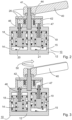
- a preferred embodiment of the valve device 10 is shown in a cross section.
- the two valves 14, 15 are arranged in the housing 12 of the valve device 10, wherein the valve housings of the valves 14, 15 are essentially formed by the housing 12.
- the pistons 18 and 19 are each displaced by a tappet 46 and 47 by the mechanical control 26.
- the mechanical control 26 has a lever 40 with a shaft 41, a cam disk 42 and a torsion spring 44.
- the cam disk 42 is attached to the shaft 41, and when the lever 40 is actuated, either the tappet 46 or the tappet 47 is pressed downwards by the cam disk 42. In this case, a rotary movement of the lever 42 is converted into a translatory movement by the cam disk 42.
- the torsion spring 44 causes a force in the direction of the basic position of the lever 40.
- the cam disk 42 has a surface with a gradient such that when the lever 40 is actuated anti-clockwise, the tappet 46 and thereby the piston 18 are pressed downwards, and when the lever 40 is actuated clockwise, the tappet 47 and thereby the piston 19 are pressed downwards. Actuating the lever 40 anti-clockwise causes a ventilation process and actuating the lever 40 clockwise causes a venting process. If the lever 40 is in the basic position, the set pressure is maintained.
- the lever 26 is turned anti-clockwise, by Fig. 3 indicated by an arrow 50.
- the cam disk 42 thereby presses the tappet 46 and thus the piston 18 downwards.
- the tappet 47 remains unloaded, so that in this embodiment a ventilation process is brought about by the actuation of the lever 26.
- FIG. 4 An embodiment of an electrical control 22 for the valve 14 of the valve device 10 is shown schematically in the Fig. 4
- the electrical control 22 has an electrical control line 50, through which a magnet 52 can be activated and energized.
- a valve 54 is opened, whereby compressed air from a compressed air reservoir, in the Fig. 4 not shown, is fed to the valve 14 via a supply line 56 so that the piston 18 is displaced.
- the supply line 56 is connected to the valve 14 in such a way that when the magnet 52 is activated, compressed air is fed into a cavity 58 above the piston 14 via the valve 54 so that the piston 14 is displaced.
- the electrical control 23 is identical in construction to the electrical control 22, but in the Fig. 4 not shown.
- FIG. 5 is a schematic representation of an embodiment of a pneumatic control 24 for the valve 14.
- the pneumatic control 24 has an external, pneumatic operating device 60 with a button 62, by means of which compressed air from a compressed air reservoir can be supplied to the valve 14 via a compressed air valve 64 and a supply line 66 when the button 62 is operated.
- the supply line 66 is integrated in this embodiment with one end in a central guide 68 of the piston 14, so that when the button 62 is actuated, a central cavity 70 is pressurized via the piston 14, whereby the piston 14 is displaced.
- the pneumatic control 25 is identical in construction to the pneumatic control 22, but in the Fig. 5 not shown.
- valve control for the valve 15, in particular the electrical control and the pneumatic control is designed identically to the valve 14.
- the Figures 1 to 5 The valves shown are 4/2 valves, but the proposed valve control can also be used for many other valves, such as 2/2, 3/2 or 5/2 valves.
- valve control described enables the construction of a valve with a three-way actuated piston. While the mechanical control directly actuates a piston mechanically, the electrical control and the pneumatic control can be operated remotely. For the electrical control and the pneumatic control, two chambers that are sealed against each other and the environment are available for each valve. This prevents mutual influence between the controls. To confirm the piston of a valve, the request from one control option is sufficient. If several control options want to actuate the same piston at the same time, this has no further effect and the control command is still executed.
Landscapes
- Engineering & Computer Science (AREA)
- General Engineering & Computer Science (AREA)
- Mechanical Engineering (AREA)
- Mechanically-Actuated Valves (AREA)
- Multiple-Way Valves (AREA)
Description
- Die Erfindung betrifft eine Ventileinrichtung für ein Fahrzeug, insbesondere ein Niveauregulierungsventil für eine Luftfederungseinrichtung eines Lastkraftfahrzeugs.
- Luftfederungseinrichtungen für Lastkraftfahrzeuge weisen üblicherweise eine Einrichtung zur Niveauregelung des Fahrzeugaufbaus gegenüber dem Fahrwerk bzw. der Fahrbahn auf. Bezüglich solcher Niveauregulierungseinrichtungen wird zwischen drei Prinzipien unterschieden: Es gibt mechanische, elektrische und pneumatisch arbeitende Ansteuerungen.
- Marktübliche Niveauregulierungsventile für eine elektronische Luftfederung bieten lediglich die Möglichkeit, das Niveau manuell durch einen ins Gerät integrierten Hebel oder mittels externen, pneumatisch mit dem Gerät verbundenen Tasten anzupassen. Ein Gerät, das beide Funktionen ineinander vereint, ist heute nicht bekannt. Vorteilhaft wäre ein solches Gerät zum Beispiel für Kühlerfahrzeuge, bei denen eine Bedienung sowohl von außen also auch aus dem Kühlkoffer möglich sein soll.
-
CN 103 253 102 B offenbart eine Ventileinrichtung, die manuell oder durch einen elektrischen Betriebsmechanismus in Positionen "Heben", "Senken" und "Fahren" gebracht werden kann. -
DE 10 2014 108 557 A1 offenbart eine Luftfederungseinrichtung zum Heben und Senken eines Fahrzeugaufbaus von luftgefederten Fahrzeugen mit Niveauregelung. Die Luftfederungseinreichung weist ein Handbetätigungselement zum manuellen Heben und Senken des Fahrzeugabbaus unter Umgehung einer Niveauregelventileinheit auf. Weiterhin kann die Luftfederungseinrichtung über ein von einem Fahrzustand abhängiges pneumatisches Signal angesteuert werden und kann die Luftfederungseinrichtung über ein vom Fahrzustand abhängiges elektrisches Signal angesteuert werden, um jeweils ohne manuellen Eingriff eine Verschiebung des Handbetätigungselements in eine Position "Fahren" einzuleiten. -
EP 2 263 893 A1 offenbart eine Schaltventileinheit zum Be- und Entlüften von Luftfederbälgen zum Heben und Senken eines Aufbaus eines Fahrzeugs. Die Schaltventileinheit ist durch manuelle Betätigung einer Betätigungseinrichtung betätigbar. - Es besteht somit ein Bedarf für eine Ventileinrichtung, die vielseitig bedienbar ist.
- Aufgabe der Erfindung ist es, eine derartige Ventileinrichtung anzugeben.
- Diese Aufgabe wird durch eine Ventileinrichtung gemäß Anspruch 1 gelöst.
- Die abhängigen Ansprüche beinhalten vorteilhafte Weiterbildungen und Verbesserungen der Erfindung entsprechend der nachfolgenden Beschreibung dieser Maßnahmen.
- Die Erfindung betrifft eine Ventileinrichtung, insbesondere für ein Fahrzeug, umfassend: ein Gehäuse mit einem ersten Ventil, wobei das Gehäuse einen Drucklufteinlass, einen Druckluftauslass und einen Entlüftungsauslass umfasst und das Ventil einen Kolben und eine Rückstellfeder umfasst. Nach der erfindungsgemäßen Lösung umfasst die Ventileinrichtung zur Betätigung des Ventils eine mechanische Ansteuerung mit einem manuellen Bedienelement, eine elektrische Ansteuerung, sowie eine pneumatische Ansteuerung.
- In einer vorteilhaften Ausführungsform umfasst die mechanische Ansteuerung einen Taster und einen Stößel oder einen Hebel, eine Welle, eine Kurvenscheibe und einen Stößel.
- In einer weiteren vorteilhaften Ausführungsform umfasst die elektrische Ansteuerung ein Magnetventil zur Steuerung einer Druckluftzufuhr für das Ventil.
- In einer weiteren vorteilhaften Ausführungsform umfasst die pneumatische Ansteuerung eine Druckluftleitung und ein externes pneumatisches Bediengerät mit einem Druckluftventil.
- Die Ventileinrichtung umfasst ein zweites Ventil, wobei die Ventileinrichtung zur Betätigung des zweiten Ventils eine mechanische Ansteuerung mit einem manuellen Bedienelement, eine elektrische Steuerung und eine pneumatische Steuerung umfasst. Die Ventile sind beispielsweise 2/2-, 3/2- oder ein 4/2-Ventile.
- In einer besonders vorteilhaften Ausführungsform sind die elektrische Ansteuerung und die pneumatische Ansteuerung des zweiten Ventils baugleich zu dem ersten Ventil ausgestaltet, und die mechanische Ansteuerung umfasst einen Hebel, eine Welle, eine Kurvenscheibe, sowie einen Stößel für jedes der Ventile. Das erste Ventil ist hierbei insbesondere als ein Belüftungsventil und das zweite Ventil als ein Entlüftungsventil ausgestaltet.
- Das zweite Ventil ist intern über zwei pneumatische Verbindungen derart mit dem ersten Ventil verbunden, dass bei einer Betätigung des ersten Ventils Druckluft vom Drucklufteinlass durch das erste und zweite Ventil zum Druckluftauslass durchgeleitet wird und bei
- Betätigung des zweiten Ventils Druckluft vom Druckluftauslass durch das zweite und erste Ventil zum Entlüftungsauslass durchgeleitet wird.
- Die Ventileinrichtung gemäß der Erfindung ist vorteilhafterweise für ein Fahrzeug, insbesondere ein Lastkraftfahrzeug, sowie Anhängerfahrzeuge mit einer Luftfederungseinrichtung verwendbar.
- Vorteilhafte Ausführungsbeispiele der Erfindung sind in den Zeichnungen dargestellt und werden nachfolgend anhand der Figuren näher erläutert.
- Es zeigen:
- Fig. 1
- eine Ventileinrichtung gemäß der Erfindung;
- Fig. 2
- ein bevorzugtes Ausführungsbeispiel der Ventileinrichtung der
Fig. 1 in einem Querschnitt; - Fig. 3
- das Ausführungsbeispiel der Ventileinrichtung der
Fig. 2 nach einer manuellen Betätigung; - Fig. 4
- ein bevorzugtes Ausführungsbeispiel der Ventileinrichtung der
Fig. 1 mit einer elektrischen Ansteuerung in einem Querschnitt; und - Fig. 5
- ein bevorzugtes Ausführungsbeispiel der Ventileinrichtung der
Fig. 1 mit einer pneumatischen Ansteuerung in einem Querschnitt. - Die vorliegende Beschreibung veranschaulicht die Prinzipien der erfindungsgemäßen Offenbarung. Es versteht sich somit, dass Fachleute in der Lage sein werden, verschiedene Anordnungen zu konzipieren, die zwar hier nicht explizit beschrieben werden, die aber Prinzipien der erfindungsgemäßen Offenbarung verkörpern und in ihrem Umfang ebenfalls geschützt sein sollen.
-
Fig. 1 zeigt schematisch eine Ventileinrichtung 10 mit einem Gehäuse 12, in dem ein erstes Ventil 14 und ein zweites Ventil 15 angeordnet sind, und das einen Drucklufteinlass 1 für eine Druckluftzufuhr, einen Druckluftauslass 2 und einen Entlüftungsauslass 3 aufweist. Das erste Ventil 14 ist insbesondere ein Belüftungsventil und weist einen Anschluss auf, der mit dem Drucklufteinlass 1 verbunden ist, und einen Anschluss, der mit dem Entlüftungsauslass 3 verbunden ist. Das zweite Ventil 15 ist insbesondere ein Entlüftungsventil und weist zwei Anschlüsse auf, die über zwei pneumatische Verbindungen 6, 7 innerhalb der Ventileinrichtung 10 mit zwei Anschlüssen des Ventils 14 verbunden sind, und zwei Anschlüsse, die mit dem Druckluftauslass 2 verbunden sind. Die pneumatischen Verbindungen 6, 7 und die Anschlüsse der Ventile 14, 15 sind insbesondere derart ausgestaltet, dass bei Betätigung des Ventils 14 Druckluft vom Drucklufteinlass 1 durch die Ventile 14, 15 zum Druckluftauslass 2 durchgeleitet wird und bei Betätigung des Ventils 15 Druckluft vom Druckluftluftauslass 2 durch die Ventile 14, 15 zum Entlüftungsauslass 3 durchgeleitet wird. - Die beiden Ventile 14, 15 sind in diesem Ausführungsbeispiel 4/2-Ventile und weisen jeweils einen Kolben 18 bzw. 19 auf, in der
Fig. 1 nur schematisch dargestellt, mit jeweils einer Rückstellfeder 20 bzw. 21, und ein Ventilgehäuse 16 bzw. 17, in dem sich jeweils der Kolben 18, 19 bewegt. Das Ventil 15 kann beispielsweise aber auch als ein 3/2-Ventil mit nur einem Anschluss für den Druckluftluftauslass 2 ausgestaltet sein. - Ventileinrichtungen dieser Art werden üblicherweise in Luftfederungsanlagen von Lastkraftwagen verwendet und sind wohlbekannt. Wird das Ventil 14 betätigt und hierdurch dessen Kolben 18 verschoben, so wird über die Anschlüsse 1 und 2 ein Druck für eine Luftfederung aufgebaut. Wird das Ventil 15 betätigt und dessen Kolben 19 verschoben, so wird über die Anschlüsse 2 und 3 der Druck abgelassen. Wird keines der Ventile 14, 15 betätigt, so wird der Druck an dem Druckluftluftauslass 2 aufrechterhalten.
- Zur Betätigung des Kolbens weist jedes der Ventile 14, 15 nach der Erfindung zur Steuerung einer Druckluftzufuhr und einer Entlüftung sowohl eine elektrische Ansteuerung 22 bzw. 23, eine pneumatische Ansteuerung 24 bzw. 25, sowie eine mechanische Ansteuerung 26, 27 auf. Die elektrische Ansteuerung 22 des Ventils 14 weist hierbei ein Magnetventil 30 mit einem Magneten 28 für das Ventil 14 auf. Die pneumatische Ansteuerung 24 weist ein pneumatisches Ventil 32, das über eine pneumatische Leitung 34 betätigbar ist, auf. Die mechanische Ansteuerung 26, 27 weist ein manuelles, integriertes Bedienelement, beispielsweise mit einem Hebel oder zwei Tastern, auf.
- Das Ventil 15 weist eine elektrische Ansteuerung 23 mit einem Magnetventil 31 auf, das einen Magneten 29 aufweist. Die pneumatische Ansteuerung 25 weist ein pneumatisches Ventil 33 auf, das über eine pneumatische Leitung 35 betätigbar ist. Die pneumatische Leitung 34 ist hierbei mit dem pneumatischen Anschluss 4 verbunden und die pneumatische Leitung 35 ist mit dem pneumatischen Anschluss 5 verbunden. Durch die Betätigung der Ventile 14 bzw. 15 kann beispielsweise ein Fahrzeugaufbau gehoben oder gesenkt werden.
- In dem Ausführungsbeispiel der
Fig. 1 weist das Ventil 14 eine mechanische Ansteuerung 26 mit einem Taster 36 und einem Stößel 38 auf, und das Ventil 15 weist eine mechanische Ansteuerung 27 mit einem Taster 37 und einem Stößel 39 auf. Bei Betätigung des Tasters 36 wird auf bekannte Weise über den Stößel 38 der Kolben 14 nach unten gedrückt und bei Betätigung des Tasters 37 wird über den Stößel 39 der Kolben 15 nach unten gedrückt. - In der
Fig. 2 ist ein bevorzugtes Ausführungsbeispiel der Ventileinrichtung 10 in einem Querschnitt dargestellt. Die beiden Ventile 14, 15 sind in dem Gehäuse 12 der Ventileinrichtung 10 angeordnet, wobei die Ventilgehäuse der Ventile 14, 15 im Wesentlichen durch das Gehäuse 12 gebildet sind. Die Kolben 18, bzw. 19 werden jeweils durch einen Stößel 46 bzw. 47 durch die mechanische Ansteuerung 26 verschoben. Die mechanische Steuerung 26 weist in diesem Ausführungsbeispiel einen Hebel 40 mit einer Welle 41, eine Kurvenscheibe 42 sowie eine Drehfeder 44 auf. Die Kurvenscheibe 42 ist an der Welle 41 befestigt, und bei Betätigung des Hebels 40 wird durch die Kurvenscheibe 42 entweder der Stößel 46 oder der Stößel 47 nach unten gedrückt. Hierbei wird eine Drehbewegung des Hebels 42 durch die Kurvenscheibe 42 in eine translatorische Bewegung umgesetzt. Die Drehfeder 44 bewirkt eine Kraft in Richtung der Grundstellung des Hebels 40. - Die Kurvenscheibe 42 weist eine Fläche mit einer Steigung auf, derart, dass bei Betätigung des Hebels 40 gegen den Uhrzeigersinn der Stößel 46 und hierdurch der Kolben 18 nach unten gedrückt wird und bei Betätigung des Hebels 40 im Uhrzeigersinn der Stößel 47 und hierdurch der Kolben 19 nach unten gedrückt wird. Die Betätigung des Hebels 40 gegen den Uhrzeigersinn bewirkt hierbei einen Belüftungsvorgang und die Betätigung des Hebels 40 im Uhrzeigersinn bewirkt einen Entlüftungsvorgang. Ist der Hebel 40 in der Grundstellung, so wird der eingestellte Druck gehalten.
- In einem Ausführungsbeispiel ist in der
Fig. 3 der Hebel 26 gegen den Uhrzeigersinn gedreht, durch in derFig. 3 durch einen Pfeil 50 angedeutet. Die Kurvenscheibe 42 drückt hierdurch den Stößel 46 und damit den Kolben 18 nach unten. Der Stößel 47 bleibt entlastet, so dass in diesem Ausführungsbeispiel ein Belüftungsvorgang durch die Betätigung des Hebels 26 bewirkt wird. - Die weiteren Bezugszeichen der
Figuren 2 und 3 entsprechen denen derFig. 1 . Die elektrischen Ansteuerungen 22, 23 sowie die pneumatischen Ansteuerungen 24, 25 sind inFig. 2 und Fig. 3 aus Gründen der Übersichtlichkeit nicht dargestellt. - Ein Ausführungsbeispiel für eine elektrische Ansteuerung 22 für das Ventil 14 der Ventileinrichtung 10 ist schematisch in der
Fig. 4 dargestellt. Die elektrische Ansteuerung 22 weist eine elektrische Steuerleitung 50 auf, durch die ein Magnet 52 aktivierbar ist und bestromt werden kann. Bei einer Bestromung des Magneten 52 wird ein Ventil 54 geöffnet, wodurch Druckluft aus einem Druckluftvorratsbehälter, in derFig. 4 nicht dargestellt, über eine Zuleitung 56 dem Ventil 14 zugeführt wird, so dass der Kolben 18 verschoben wird. Die Zuleitung 56 ist hierbei derart an das Ventil 14 angeschlossen, dass bei einer Aktivierung des Magneten 52 über das Ventil 54 Druckluft in einen Hohlraum 58 über dem Kolben 14 zugeführt wird, so dass sich der Kolben 14 verschiebt. Die elektrische Ansteuerung 23 ist baugleich zu der elektrischen Ansteuerung 22, aber in derFig. 4 nicht dargestellt. - In der
Fig. 5 ist schematisch ein Ausführungsbeispiel für eine pneumatische Ansteuerung 24 für das Ventil 14 dargestellt. Die pneumatische Ansteuerung 24 weist ein externes, pneumatisches Bediengerät 60 mit einem Taster 62 auf, durch das bei Bedienung des Tasters 62 über ein Druckluftventil 64 und eine Zuleitung 66 Druckluft aus einem Druckluftvorratsbehälter dem Ventil 14 zugeführt werden kann. Die Zuleitung 66 ist in diesem Ausführungsbeispiel mit einem Ende in eine zentrale Führung 68 des Kolbens 14 integriert, sodass bei Betätigung ist des Tasters 62 ein zentraler Hohlraum 70 über den Kolben 14 unter Druck gesetzt wird, wodurch der Kolben 14 verschoben wird. Die pneumatische Ansteuerung 25 ist baugleich zu der pneumatischen Ansteuerung 22, aber in derFig. 5 nicht dargestellt. - In einem bevorzugten Ausführungsbeispiel ist die Ventilsteuerung für das Ventil 15, insbesondere die elektrische Ansteuerung und die pneumatische Ansteuerung, baugleich zu dem Ventil 14 ausgeführt. Die in den
Figuren 1 bis 5 dargestellten Ventile sind 4/2-Ventile, die vorgeschlagene Ventilsteuerung lässt sich jedoch auch für viele weitere Ventile, wie beispielsweise 2/2-, 3/2- oder 5/2-Ventile, verwenden. - Die beschriebene Ventilsteuerung ermöglicht den Aufbau eines Ventils mit einem dreifach betätigten Kolben. Während hierbei die mechanische Ansteuerung einen Kolben direkt mechanisch betätigt, können die elektrische Ansteuerung und die pneumatische Ansteuerung aus der Ferne bedient werden. Für die elektrische Ansteuerung und für pneumatische Ansteuerung stehen für jedes Ventil zwei gegeneinander und zur Umgebung abgedichtete Kammern zur Verfügung. So wird eine gegenseitige Beeinflussung zwischen den Steuerungen ausgeschlossen. Um den Kolben eines Ventils zu bestätigen, genügt die Anforderung von einer Kontrollmöglichkeit. Wollen mehrere Kontrollmöglichkeiten denselben Kolben gleichzeitig betätigen, so hat dies keinen weiteren Effekt und der Kontrollbefehl wird weiterhin ausgeführt.
-
- 1
- Drucklufteinlass
- 2
- Druckluftauslass
- 3
- Entlüftungsauslass
- 4, 5
- pneumatische Anschlüsse
- 6, 7
- pneumatische Verbindungen
- 10
- Ventileinrichtung
- 12
- Gehäuse
- 14, 15
- Ventile
- 16, 17
- Ventilgehäuse
- 18, 19
- Kolben
- 20, 21
- Rückstellfedern
- 22, 23
- elektrische Ansteuerungen
- 24, 25
- pneumatische Ansteuerungen
- 26, 27
- mechanische Ansteuerungen
- 28, 29
- Magnete
- 30, 31
- Magnetventile
- 32, 33
- pneumatische Ventile
- 34, 35
- pneumatische Leitungen
- 36, 37
- Taster
- 38, 39
- Stößel
- 40
- Hebel
- 41
- Welle
- 42
- Kurvenscheibe
- 44
- Drehfeder
- 46, 47
- Stößel
- 50
- Steuerleitung
- 52
- Magnet
- 54
- Ventil
- 56
- Zuleitung
- 58
- Hohlraum
- 60
- pneumatisches Bediengerät
- 62
- Taster
- 64
- Druckluftventil
- 66
- Zuleitung
- 68
- zentrale Führung
- 70
- Hohlraum
Claims (7)
- Ventileinrichtung (10), insbesondere für ein Fahrzeug, umfassend: ein Gehäuse (12) mit einem ersten Ventil (14), wobei das Gehäuse einen Drucklufteinlass (1), einen Druckluftluftauslass (2) und einen Entlüftungsauslass (3) umfasst und das Ventil (12) einen Kolben (18) und eine Rückstellfeder (20) umfasst, wobei zur Betätigung des Ventils (14) die Ventileinrichtung (10) eine mechanische Ansteuerung (26) mit einem manuellen Bedienelement (40, 41, 42, 44, 46), eine elektrische Ansteuerung (22) und eine pneumatische Ansteuerung (24) umfasst,umfassend ein zweites Ventil (15), wobei die Ventileinrichtung zur Betätigung des zweiten Ventils eine mechanische Ansteuerung (27) mit einem manuellen Bedienelement (40, 41, 42, 44, 47), eine elektrische Ansteuerung (23) und eine pneumatische Ansteuerung (25) umfasst, wobei das erste Ventil (14) als ein Belüftungsventil und das zweite Ventil (15) als ein Entlüftungsventil ausgestaltet sind,dadurch gekennzeichnet, dassdas zweite Ventil (15) intern über zwei pneumatischen Verbindungen (6, 7) derart mit dem ersten Ventil (14) verbunden ist, dass bei einer Betätigung des ersten Ventils (14) Druckluft vom Drucklufteinlass (1) durch das erste und zweite Ventil (14, 15) zum Druckluftluftauslassanschluss (2) durchgeleitet wird und bei Betätigung des zweiten Ventils (15) Druckluft vom Druckluftluftauslassanschluss (2) durch das zweite und erste Ventil (14, 15) zum Entlüftungsauslass (3) durchgeleitet wird.
- Ventileinrichtung (10) nach Anspruch 1, wobei die mechanische Ansteuerung (26) einen Taster (36) und einen Stößel (38) oder einen Hebel (40), eine Welle (41), eine Kurvenscheibe (42), eine Drehfeder (44) und einen Stößel (46) umfasst.
- Ventileinrichtung (10) nach Anspruch 1 oder 2, wobei die elektrische Ansteuerung (22) ein Magnetventil (52, 54) zur Steuerung einer Druckluftzufuhr für das Ventil (14) umfasst.
- Ventileinrichtung (10) nach Anspruch 1, 2 oder 3, wobei die pneumatische Ansteuerung (24) eine Druckluftleitung (66, 68) und ein externes pneumatisches Bediengerät (60) mit einem Druckluftventil (64) umfasst.
- Ventileinrichtung (10) nach einem der vorhergehenden Ansprüche, wobei die Ventile (14, 15) 2/2-, 3/2- oder 4/2-Ventile sind.
- Ventileinrichtung (10) nach einem der vorhergehenden Ansprüche, wobei die elektrische Ansteuerung (23) und die pneumatische Ansteuerung (25) des zweiten Ventils (15) baugleich zu dem ersten Ventil (14) ausgestaltet sind, und die mechanische Ansteuerung (26, 27) der Ventileinrichtung (10) einen Hebel (40), eine Welle (41), eine Kurvenscheibe (42), eine Drehfeder (44), sowie einen Stößel für jedes der Ventile (14, 15) umfasst.
- Fahrzeug, insbesondere Lastkraftfahrzeug oder Anhängerfahrzeug, mit einer Ventileinrichtung (10) nach einem der Ansprüche 1 bis 6.
Applications Claiming Priority (1)
| Application Number | Priority Date | Filing Date | Title |
|---|---|---|---|
| DE102021125123.0A DE102021125123A1 (de) | 2021-09-28 | 2021-09-28 | Ventileinrichtung für ein Fahrzeug |
Publications (2)
| Publication Number | Publication Date |
|---|---|
| EP4155593A1 EP4155593A1 (de) | 2023-03-29 |
| EP4155593B1 true EP4155593B1 (de) | 2025-02-19 |
Family
ID=83283282
Family Applications (1)
| Application Number | Title | Priority Date | Filing Date |
|---|---|---|---|
| EP22195078.5A Active EP4155593B1 (de) | 2021-09-28 | 2022-09-12 | Ventileinrichtung für ein fahrzeug |
Country Status (2)
| Country | Link |
|---|---|
| EP (1) | EP4155593B1 (de) |
| DE (1) | DE102021125123A1 (de) |
Family Cites Families (3)
| Publication number | Priority date | Publication date | Assignee | Title |
|---|---|---|---|---|
| CN101725756A (zh) * | 2008-10-14 | 2010-06-09 | 威伯科有限公司 | 阀系统、带有它的阀装置和用于空气悬架设备的阀装置 |
| EP2263893A1 (de) * | 2009-06-10 | 2010-12-22 | Haldex Brake Products GmbH | Schaltventileinheit zum Be- und Entlüften von Federbälgen eines Fahrzeugs oder Anhängers |
| DE102014108557A1 (de) | 2014-06-18 | 2015-12-24 | Knorr-Bremse Systeme für Nutzfahrzeuge GmbH | Luftfederungseinrichtung zum Heben und Senken eines Fahrzeugaufbaus |
-
2021
- 2021-09-28 DE DE102021125123.0A patent/DE102021125123A1/de active Pending
-
2022
- 2022-09-12 EP EP22195078.5A patent/EP4155593B1/de active Active
Also Published As
| Publication number | Publication date |
|---|---|
| DE102021125123A1 (de) | 2023-03-30 |
| EP4155593A1 (de) | 2023-03-29 |
Similar Documents
| Publication | Publication Date | Title |
|---|---|---|
| EP1687160B1 (de) | Luftfederungseinrichtung für ein fahrzeug | |
| EP1986874B1 (de) | Ventileinrichtung zur manuellen veränderung der niveaulage eines luftgefederten fahrzeuges | |
| EP1687159B1 (de) | Ventileinrichtung für eine luftfederungseinrichtung für ein fahrzeug | |
| DE102007008159B4 (de) | Luftfederungseinrichtung mit elektrisch betätigtem Sperrventil | |
| EP1888389B1 (de) | Parkbremseinrichtung eines fahrzeugs mit elektro-pneumatischer notlöseeinrichtung | |
| DE102007052521A1 (de) | Druckmittelbetätigte Bremseinrichtung eines Zugfahrzeugs mit einem gegenläufige Drücke für Anhängerbremsen erzeugenden Feststellbremsmodul | |
| WO2009039908A1 (de) | Ventileinrichtung für eine luftfederungsanlage | |
| DE102008015249A1 (de) | Druckmittelbetätigte Bremsanlage eines Fahrzeugs mit wenigstens einem bistabilen Schieberventil | |
| EP2540538B1 (de) | Luftfederungsanlage | |
| EP2177381B1 (de) | Ventileinrichtung für eine Luftfederungsanlage | |
| EP2177383B1 (de) | Ventileinrichtung für eine Luftfederungsanlage | |
| EP4155593B1 (de) | Ventileinrichtung für ein fahrzeug | |
| DE3809338C1 (en) | Control valve with relay action for motor vehicles or trailers | |
| DE102013100295B4 (de) | Luftfederanlage für ein Fahrzeug | |
| EP4155592B1 (de) | Ventileinrichtung, sowie fahrzeug mit einer luftfederungseinrichtung | |
| DE19905113B4 (de) | Liftachsventil zum Steuern der Liftachsfunktionen eines Fahrzeugs mit mehreren Hinterachsen | |
| DE4414868C1 (de) | Steueranlage zum willkürlichen Heben und Senken des Fahrzeugaufbaus von luftgefederten Fahrzeugen | |
| DE3920096A1 (de) | Druckluftbremseinrichtung | |
| EP2177382B1 (de) | Ventilanordnung mit einem ersten und einem zweiten Sitzventil sowie Ventileinrichtung mit einer solchen Ventilanordnung | |
| EP4170210B1 (de) | Ventileinrichtung sowie fahrzeug mit einer ventileinrichtung | |
| EP0026504B1 (de) | Absenkeinrichtung einer Führerbremsventilanlage für indirekt wirkende Druckluftbremsen von Schienenfahrzeugen | |
| EP4170211A1 (de) | Ventileinheit, betätigungseinheit, ventileinrichtung, geräteplattform, sowie fahrzeug | |
| EP0292829A2 (de) | Zweikreis-Bremsventil, insbesondere Fussbremsventil für Bremsanlagen von Fahrzeugen | |
| EP2179872A1 (de) | Luftfederungseinrichtung mit elektro-mechanischer Stelleinrichtung zum Rückstellen eines Schaltventils in die Stellung Fahrt |
Legal Events
| Date | Code | Title | Description |
|---|---|---|---|
| PUAI | Public reference made under article 153(3) epc to a published international application that has entered the european phase |
Free format text: ORIGINAL CODE: 0009012 |
|
| STAA | Information on the status of an ep patent application or granted ep patent |
Free format text: STATUS: THE APPLICATION HAS BEEN PUBLISHED |
|
| AK | Designated contracting states |
Kind code of ref document: A1 Designated state(s): AL AT BE BG CH CY CZ DE DK EE ES FI FR GB GR HR HU IE IS IT LI LT LU LV MC MK MT NL NO PL PT RO RS SE SI SK SM TR |
|
| STAA | Information on the status of an ep patent application or granted ep patent |
Free format text: STATUS: REQUEST FOR EXAMINATION WAS MADE |
|
| 17P | Request for examination filed |
Effective date: 20230728 |
|
| RBV | Designated contracting states (corrected) |
Designated state(s): AL AT BE BG CH CY CZ DE DK EE ES FI FR GB GR HR HU IE IS IT LI LT LU LV MC MK MT NL NO PL PT RO RS SE SI SK SM TR |
|
| RIN1 | Information on inventor provided before grant (corrected) |
Inventor name: STENDER, AXEL Inventor name: GERLACH, STEFFEN Inventor name: DIET, FELIX |
|
| GRAP | Despatch of communication of intention to grant a patent |
Free format text: ORIGINAL CODE: EPIDOSNIGR1 |
|
| STAA | Information on the status of an ep patent application or granted ep patent |
Free format text: STATUS: GRANT OF PATENT IS INTENDED |
|
| INTG | Intention to grant announced |
Effective date: 20240829 |
|
| GRAJ | Information related to disapproval of communication of intention to grant by the applicant or resumption of examination proceedings by the epo deleted |
Free format text: ORIGINAL CODE: EPIDOSDIGR1 |
|
| STAA | Information on the status of an ep patent application or granted ep patent |
Free format text: STATUS: REQUEST FOR EXAMINATION WAS MADE |
|
| GRAP | Despatch of communication of intention to grant a patent |
Free format text: ORIGINAL CODE: EPIDOSNIGR1 |
|
| INTC | Intention to grant announced (deleted) | ||
| STAA | Information on the status of an ep patent application or granted ep patent |
Free format text: STATUS: GRANT OF PATENT IS INTENDED |
|
| INTG | Intention to grant announced |
Effective date: 20241128 |
|
| GRAS | Grant fee paid |
Free format text: ORIGINAL CODE: EPIDOSNIGR3 |
|
| GRAA | (expected) grant |
Free format text: ORIGINAL CODE: 0009210 |
|
| STAA | Information on the status of an ep patent application or granted ep patent |
Free format text: STATUS: THE PATENT HAS BEEN GRANTED |
|
| AK | Designated contracting states |
Kind code of ref document: B1 Designated state(s): AL AT BE BG CH CY CZ DE DK EE ES FI FR GB GR HR HU IE IS IT LI LT LU LV MC MK MT NL NO PL PT RO RS SE SI SK SM TR |
|
| REG | Reference to a national code |
Ref country code: GB Ref legal event code: FG4D Free format text: NOT ENGLISH |
|
| REG | Reference to a national code |
Ref country code: CH Ref legal event code: EP |
|
| REG | Reference to a national code |
Ref country code: DE Ref legal event code: R096 Ref document number: 502022002925 Country of ref document: DE |
|
| REG | Reference to a national code |
Ref country code: IE Ref legal event code: FG4D Free format text: LANGUAGE OF EP DOCUMENT: GERMAN |
|
| REG | Reference to a national code |
Ref country code: NL Ref legal event code: MP Effective date: 20250219 |
|
| PG25 | Lapsed in a contracting state [announced via postgrant information from national office to epo] |
Ref country code: RS Free format text: LAPSE BECAUSE OF FAILURE TO SUBMIT A TRANSLATION OF THE DESCRIPTION OR TO PAY THE FEE WITHIN THE PRESCRIBED TIME-LIMIT Effective date: 20250519 |
|
| PG25 | Lapsed in a contracting state [announced via postgrant information from national office to epo] |
Ref country code: FI Free format text: LAPSE BECAUSE OF FAILURE TO SUBMIT A TRANSLATION OF THE DESCRIPTION OR TO PAY THE FEE WITHIN THE PRESCRIBED TIME-LIMIT Effective date: 20250219 |
|
| PG25 | Lapsed in a contracting state [announced via postgrant information from national office to epo] |
Ref country code: PL Free format text: LAPSE BECAUSE OF FAILURE TO SUBMIT A TRANSLATION OF THE DESCRIPTION OR TO PAY THE FEE WITHIN THE PRESCRIBED TIME-LIMIT Effective date: 20250219 |
|
| PG25 | Lapsed in a contracting state [announced via postgrant information from national office to epo] |
Ref country code: ES Free format text: LAPSE BECAUSE OF FAILURE TO SUBMIT A TRANSLATION OF THE DESCRIPTION OR TO PAY THE FEE WITHIN THE PRESCRIBED TIME-LIMIT Effective date: 20250219 |
|
| REG | Reference to a national code |
Ref country code: LT Ref legal event code: MG9D |
|
| PG25 | Lapsed in a contracting state [announced via postgrant information from national office to epo] |
Ref country code: NO Free format text: LAPSE BECAUSE OF FAILURE TO SUBMIT A TRANSLATION OF THE DESCRIPTION OR TO PAY THE FEE WITHIN THE PRESCRIBED TIME-LIMIT Effective date: 20250519 Ref country code: IS Free format text: LAPSE BECAUSE OF FAILURE TO SUBMIT A TRANSLATION OF THE DESCRIPTION OR TO PAY THE FEE WITHIN THE PRESCRIBED TIME-LIMIT Effective date: 20250619 |
|
| PG25 | Lapsed in a contracting state [announced via postgrant information from national office to epo] |
Ref country code: NL Free format text: LAPSE BECAUSE OF FAILURE TO SUBMIT A TRANSLATION OF THE DESCRIPTION OR TO PAY THE FEE WITHIN THE PRESCRIBED TIME-LIMIT Effective date: 20250219 |
|
| PG25 | Lapsed in a contracting state [announced via postgrant information from national office to epo] |
Ref country code: HR Free format text: LAPSE BECAUSE OF FAILURE TO SUBMIT A TRANSLATION OF THE DESCRIPTION OR TO PAY THE FEE WITHIN THE PRESCRIBED TIME-LIMIT Effective date: 20250219 |
|
| PG25 | Lapsed in a contracting state [announced via postgrant information from national office to epo] |
Ref country code: LV Free format text: LAPSE BECAUSE OF FAILURE TO SUBMIT A TRANSLATION OF THE DESCRIPTION OR TO PAY THE FEE WITHIN THE PRESCRIBED TIME-LIMIT Effective date: 20250219 Ref country code: PT Free format text: LAPSE BECAUSE OF FAILURE TO SUBMIT A TRANSLATION OF THE DESCRIPTION OR TO PAY THE FEE WITHIN THE PRESCRIBED TIME-LIMIT Effective date: 20250620 |
|
| PG25 | Lapsed in a contracting state [announced via postgrant information from national office to epo] |
Ref country code: BG Free format text: LAPSE BECAUSE OF FAILURE TO SUBMIT A TRANSLATION OF THE DESCRIPTION OR TO PAY THE FEE WITHIN THE PRESCRIBED TIME-LIMIT Effective date: 20250219 Ref country code: GR Free format text: LAPSE BECAUSE OF FAILURE TO SUBMIT A TRANSLATION OF THE DESCRIPTION OR TO PAY THE FEE WITHIN THE PRESCRIBED TIME-LIMIT Effective date: 20250520 |
|
| PG25 | Lapsed in a contracting state [announced via postgrant information from national office to epo] |
Ref country code: SE Free format text: LAPSE BECAUSE OF FAILURE TO SUBMIT A TRANSLATION OF THE DESCRIPTION OR TO PAY THE FEE WITHIN THE PRESCRIBED TIME-LIMIT Effective date: 20250219 |
|
| PG25 | Lapsed in a contracting state [announced via postgrant information from national office to epo] |
Ref country code: SM Free format text: LAPSE BECAUSE OF FAILURE TO SUBMIT A TRANSLATION OF THE DESCRIPTION OR TO PAY THE FEE WITHIN THE PRESCRIBED TIME-LIMIT Effective date: 20250219 |
|
| PG25 | Lapsed in a contracting state [announced via postgrant information from national office to epo] |
Ref country code: DK Free format text: LAPSE BECAUSE OF FAILURE TO SUBMIT A TRANSLATION OF THE DESCRIPTION OR TO PAY THE FEE WITHIN THE PRESCRIBED TIME-LIMIT Effective date: 20250219 |
|
| PGFP | Annual fee paid to national office [announced via postgrant information from national office to epo] |
Ref country code: DE Payment date: 20250702 Year of fee payment: 4 |
|
| PG25 | Lapsed in a contracting state [announced via postgrant information from national office to epo] |
Ref country code: IT Free format text: LAPSE BECAUSE OF FAILURE TO SUBMIT A TRANSLATION OF THE DESCRIPTION OR TO PAY THE FEE WITHIN THE PRESCRIBED TIME-LIMIT Effective date: 20250219 |
|
| PGFP | Annual fee paid to national office [announced via postgrant information from national office to epo] |
Ref country code: AT Payment date: 20251020 Year of fee payment: 4 |
|
| PG25 | Lapsed in a contracting state [announced via postgrant information from national office to epo] |
Ref country code: EE Free format text: LAPSE BECAUSE OF FAILURE TO SUBMIT A TRANSLATION OF THE DESCRIPTION OR TO PAY THE FEE WITHIN THE PRESCRIBED TIME-LIMIT Effective date: 20250219 Ref country code: CZ Free format text: LAPSE BECAUSE OF FAILURE TO SUBMIT A TRANSLATION OF THE DESCRIPTION OR TO PAY THE FEE WITHIN THE PRESCRIBED TIME-LIMIT Effective date: 20250219 |
|
| PG25 | Lapsed in a contracting state [announced via postgrant information from national office to epo] |
Ref country code: RO Free format text: LAPSE BECAUSE OF FAILURE TO SUBMIT A TRANSLATION OF THE DESCRIPTION OR TO PAY THE FEE WITHIN THE PRESCRIBED TIME-LIMIT Effective date: 20250219 |
|
| PG25 | Lapsed in a contracting state [announced via postgrant information from national office to epo] |
Ref country code: SK Free format text: LAPSE BECAUSE OF FAILURE TO SUBMIT A TRANSLATION OF THE DESCRIPTION OR TO PAY THE FEE WITHIN THE PRESCRIBED TIME-LIMIT Effective date: 20250219 |
|
| REG | Reference to a national code |
Ref country code: DE Ref legal event code: R097 Ref document number: 502022002925 Country of ref document: DE |
|
| PLBE | No opposition filed within time limit |
Free format text: ORIGINAL CODE: 0009261 |
|
| STAA | Information on the status of an ep patent application or granted ep patent |
Free format text: STATUS: NO OPPOSITION FILED WITHIN TIME LIMIT |
|
| 26N | No opposition filed |
Effective date: 20251120 |