EP4155586B1 - Pressure vessel and refrigeration device - Google Patents
Pressure vessel and refrigeration device Download PDFInfo
- Publication number
- EP4155586B1 EP4155586B1 EP21809088.4A EP21809088A EP4155586B1 EP 4155586 B1 EP4155586 B1 EP 4155586B1 EP 21809088 A EP21809088 A EP 21809088A EP 4155586 B1 EP4155586 B1 EP 4155586B1
- Authority
- EP
- European Patent Office
- Prior art keywords
- pipe
- axial direction
- vessel body
- pressure vessel
- pipe axial
- Prior art date
- Legal status (The legal status is an assumption and is not a legal conclusion. Google has not performed a legal analysis and makes no representation as to the accuracy of the status listed.)
- Active
Links
Images


Classifications
-
- F—MECHANICAL ENGINEERING; LIGHTING; HEATING; WEAPONS; BLASTING
- F16—ENGINEERING ELEMENTS AND UNITS; GENERAL MEASURES FOR PRODUCING AND MAINTAINING EFFECTIVE FUNCTIONING OF MACHINES OR INSTALLATIONS; THERMAL INSULATION IN GENERAL
- F16J—PISTONS; CYLINDERS; SEALINGS
- F16J12/00—Pressure vessels in general
-
- F—MECHANICAL ENGINEERING; LIGHTING; HEATING; WEAPONS; BLASTING
- F25—REFRIGERATION OR COOLING; COMBINED HEATING AND REFRIGERATION SYSTEMS; HEAT PUMP SYSTEMS; MANUFACTURE OR STORAGE OF ICE; LIQUEFACTION SOLIDIFICATION OF GASES
- F25B—REFRIGERATION MACHINES, PLANTS OR SYSTEMS; COMBINED HEATING AND REFRIGERATION SYSTEMS; HEAT PUMP SYSTEMS
- F25B41/00—Fluid-circulation arrangements
- F25B41/40—Fluid line arrangements
-
- F—MECHANICAL ENGINEERING; LIGHTING; HEATING; WEAPONS; BLASTING
- F25—REFRIGERATION OR COOLING; COMBINED HEATING AND REFRIGERATION SYSTEMS; HEAT PUMP SYSTEMS; MANUFACTURE OR STORAGE OF ICE; LIQUEFACTION SOLIDIFICATION OF GASES
- F25B—REFRIGERATION MACHINES, PLANTS OR SYSTEMS; COMBINED HEATING AND REFRIGERATION SYSTEMS; HEAT PUMP SYSTEMS
- F25B43/00—Arrangements for separating or purifying gases or liquids; Arrangements for vaporising the residuum of liquid refrigerant, e.g. by heat
- F25B43/006—Accumulators
-
- F—MECHANICAL ENGINEERING; LIGHTING; HEATING; WEAPONS; BLASTING
- F25—REFRIGERATION OR COOLING; COMBINED HEATING AND REFRIGERATION SYSTEMS; HEAT PUMP SYSTEMS; MANUFACTURE OR STORAGE OF ICE; LIQUEFACTION SOLIDIFICATION OF GASES
- F25B—REFRIGERATION MACHINES, PLANTS OR SYSTEMS; COMBINED HEATING AND REFRIGERATION SYSTEMS; HEAT PUMP SYSTEMS
- F25B13/00—Compression machines, plants or systems, with reversible cycle
Definitions
- the present invention relates to a pressure vessel.
- An air conditioner configured to execute refrigeration cycle operation includes a refrigerant circuit having pressure vessels such as a compressor, an accumulator, and a receiver, and a refrigerant pipe connected to each of the pressure vessels.
- Patent Literature 1 discloses adopting a refrigerant pipe made of less expensive stainless steel in place of a refrigerant pipe made of copper exerting excellent processability such as bending and excellent heat conductivity.
- the pressure vessels provided on the refrigerant circuit each include a vessel body, an inlet pipe causing a refrigerant to flow into the vessel body, and an outlet pipe causing the refrigerant to flow out of the vessel body.
- the vessel body is made of iron whereas the inlet pipe and the outlet pipe are made of copper.
- the inlet pipe and the outlet pipe may be made of stainless steel in consideration of cost or the like.
- a pressure vessel and a refrigeration apparatus are also known from CN 103 983 055 A that describes a vapor-liquid separator input and output structure which comprises a tank, an upper end cover, a stainless steel input pipe and a stainless steel output pipe, wherein the upper end cover covers the end part of the tank and is provided with an inlet, an outlet and flanging parts at the inlet and the outlet, the stainless steel input pipe penetrates through the inlet, the stainless steel output pipe penetrates through the outlet, the outer end of the stainless steel input pipe and the outer end of the stainless steel output pipe are respectively provided with a flaring part, a copper insertion pipe is inserted into each flaring part, and the bottom end of each copper insertion pipe, each flaring part and each flanging part are fixed in a welding manner for forming a five-layer structure consisting of a copper insertion pipe, a
- the inlet pipe and/or the outlet pipe includes the first portion made of stainless steel and the second portion made of a material whose main component is copper, and the second portion is connected to the vessel body.
- the second portion can thus be connected to the vessel body in a manner similar to a conventional technique for an inlet pipe and/or an outlet pipe made of copper.
- the first portion has an outer circumferential surface connected with an inner circumferential surface of the second portion
- the second portion has an end surface on the second side in the pipe axial direction, the end surface being disposed flush with an end surface on the second side in the pipe axial direction of the first portion, or projecting toward the second side in the pipe axial direction than the end surface of the first portion.
- the first portion does not project toward the second side in the pipe axial direction than the second portion, for reduction in entire size of the inlet pipe and/or the outlet pipe.
- a different second pipe is connected to an end on the second side in the pipe axial direction of the second portion.
- the vessel body includes a joint tube made of iron, and the second portion is connected to the joint tube.
- the second portion is connected to an end on the first side in the pipe axial direction of the joint tube, and a different third pipe is connected to an end on the second side in the pipe axial direction of the j oint tube.
- the inlet pipe and/or the outlet pipe and the third pipe disposed in the vessel body can be connected to each other via the joint tube.
- the end surface on the second side in the pipe axial direction of the second portion projects toward the second side in the pipe axial direction than the end surface on the second side in the pipe axial direction of the first portion.
- the second portion and the third pipe connected via the joint tube are less likely to form any gap therebetween, inhibiting entry or the like of the refrigerant into the gap.
- the second portion has a portion extending into the vessel body.
- the inner pipe disposed in the vessel body can be constituted by the second portion thus extended, achieving reduction in the number of components of the pipe.
- the end on the second side in the pipe axial direction of the first portion is provided with a minor diameter portion reduced in outer diameter, and the minor diameter portion has an outer circumferential surface connected to the inner circumferential surface of the second portion.
- the minor diameter portion of the first portion is inserted to the second portion and the end of the second portion is made in contact with a portion around a proximal end of the minor diameter portion, for positioning in the pipe axial direction of the first portion and the second portion.
- the first portion has a portion overlapped with the vessel body in a pipe diameter direction.
- the first portion stronger than the second portion is overlapped with the vessel body in the pipe diameter direction, for improvement in connection strength between the vessel body and the inlet pipe and/or the outlet pipe.
- the end on the first side in the pipe axial direction of the first portion is provided with a plated portion made of a material whose main component is copper or a tube made of a material whose main component is copper.
- a refrigerant pipe made of copper can be connected easily to the end of the first portion made of stainless steel, with use of an inexpensive brazing material.
- the present invention provides a refrigeration apparatus including the pressure vessel according to any one of (1) to (10) described above.
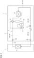
- FIG. 1 is a schematic configuration diagram of a refrigeration apparatus including a pressure vessel according to the first embodiment of the present invention.
- a refrigeration apparatus 1 exemplifies an air conditioner configured to condition indoor temperature and indoor humidity, and includes an outdoor unit 2 disposed outdoors and an indoor unit 3 disposed indoors.
- the outdoor unit 2 and the indoor unit 3 are connected to each other via a refrigerant pipe 10.
- the refrigeration apparatus 1 includes a refrigerant circuit 4 configured to execute vapor compression refrigeration cycle operation.
- the refrigerant circuit 4 includes a plurality of element components and the refrigerant pipe 10 connecting the plurality of element components.
- the refrigerant circuit 4 includes, as the element components, an indoor heat exchanger 11, a compressor 12, a muffler 13, an outdoor heat exchanger 14, an expansion mechanism 15, an accumulator 16, a four-way switching valve (switching mechanism) 17, and the like, which are connected via the refrigerant pipe 10.
- the refrigerant pipe 10 includes a liquid pipe 10L and a gas pipe 10G.
- the liquid pipe 10L and the gas pipe 10G are provided with a liquid shutoff valve 18L and a gas shutoff valve 18G, respectively.
- the indoor heat exchanger 11 is provided in the indoor unit 3 and executes heat exchange between a refrigerant and indoor air.
- Examples of the indoor heat exchanger 11 include a fin-and-tube heat exchanger of a cross-fin type and a heat exchanger of a microchannel type.
- the indoor heat exchanger 11 is provided therearound with an indoor fan (not depicted) configured to send indoor air to the indoor heat exchanger 11 and send conditioned air to indoors.
- the compressor 12, the muffler 13, the outdoor heat exchanger 14, the expansion mechanism 15, the accumulator 16, and the four-way switching valve 17 are provided in the outdoor unit 2.
- the compressor 12 is configured to compress a refrigerant sucked from an inlet pipe and discharge the compressed refrigerant from an outlet pipe. Examples of the compressor 12 include various compressors such as a scroll compressor.
- the muffler 13 inhibits pressure pulsation of the refrigerant discharged from the compressor 12.
- the outlet pipe of the compressor 12 and the four-way switching valve 17 may interpose an oil separator in place of or in addition to the muffler 13.
- the oil separator is configured to separate lubricant from fluid mixture that contains the lubricant and a refrigerant and is discharged from the compressor 12.
- the outdoor heat exchanger 14 executes heat exchange between the refrigerant and outdoor air.
- Examples of the outdoor heat exchanger 14 include a fin-and-tube heat exchanger of a cross-fin type and a heat exchanger of a microchannel type.
- the outdoor heat exchanger 14 is provided therearound with an outdoor fan configured to send outdoor air to the outdoor heat exchanger 14.
- the expansion mechanism 15 is disposed between the outdoor heat exchanger 14 and the indoor heat exchanger 11 on the refrigerant pipe 10 of the refrigerant circuit 4, and expands the incoming refrigerant to be decompressed to have predetermined pressure.
- Examples of the expansion mechanism 15 include an electronic expansion valve having a variable opening degree, and a capillary tube.
- the accumulator 16 is disposed between a suction port of the compressor 12 and the four-way switching valve 17 in the refrigerant circuit 4, and is configured to separate the incoming refrigerant into a gas refrigerant and a liquid refrigerant. The gas refrigerant thus separated by the accumulator 16 is sucked into the compressor 12.
- the four-way switching valve 17 is configured to be switchable between a first state indicated by a solid line and a second state indicated by a broken line in FIG. 1 .
- the four-way switching valve 17 is switched into the first state while the air conditioner 1 executes cooling operation, and the four-way switching valve 17 is switched into the second state while the air conditioner 1 executes heating operation.
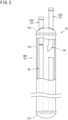
- FIG. 2 is a front view (partially sectional view) of an exemplary pressure vessel according to the first embodiment of the present invention.
- FIG. 3 is a perspective view of another exemplary pressure vessel.
- the pressure vessel depicted in FIG. 2 is the accumulator 16.
- the accumulator 16 includes a vessel body 21, an inlet pipe 22, and an outlet pipe 23.
- the vessel body 21 constitutes a primary part of the accumulator 16 and is configured to contain a refrigerant.
- the vessel body 21 includes a trunk 21a having a cylindrical shape, and two lids 21b and 21c closing both longitudinal ends of the trunk 21a.
- the present specification will also refer to an axial direction including a center in a transverse section of a pipe such as the inlet pipe 22 or the outlet pipe 23, as a "pipe axial direction”.
- a radial direction of a pipe perpendicular to the pipe axial direction will also be called a "pipe diameter direction”.
- An end or an end surface on a first side in the pipe axial direction of the pipe will also be called a "first end” or a “first end surface”
- an end or an end surface on a second side in the pipe axial direction will also be called a "second end” or a "second end surface”.
- Each of the "first end” and the “second end” in the pipe axial direction of the pipe refers to a region positioned at an end in the pipe axial direction of the pipe, such as a region adjacent to the "first end surface” or the “second end surface”, and may not necessarily include the “first end surface” or the “second end surface” in the pipe axial direction.
- the inlet pipe 22 is provided on an upper part of the vessel body 21 (the upper lid 21b).
- the inlet pipe 22 has a first end (upper end) in the pipe axial direction, which projects from the vessel body 21.
- the first end of the inlet pipe 22 is connected to the four-way switching valve 17 (see FIG. 1 ) via the refrigerant pipe 10.
- the inlet pipe 22 has a second end (lower end) in the pipe axial direction, which is disposed in the vessel body 21.
- the outlet pipe 23 is disposed on the upper part of the vessel body 21 (upper lid 21b) and adjacent to the inlet pipe 22.
- the outlet pipe 23 has a first end (upper end) in the pipe axial direction, which projects from the vessel body 21.
- the first end of the outlet pipe 23 is connected to the compressor 12 (see FIG. 1 ) via the refrigerant pipe 10.
- the outlet pipe 23 has a second end (lower end) in the pipe axial direction, which is disposed in the vessel body 21.
- the accumulator 16 includes two inner pipes 24 and 25 disposed in the vessel body 21.
- the inner pipe 24 extends downward from the second end of the inlet pipe 22.
- the inner pipe 25 extends downward from the second end of the outlet pipe 23, is bent upward into a U shape in a lower part of the vessel body 21, and extends into the upper part of the vessel body 21.
- the pressure vessel depicted in FIG. 3 is the compressor 12.
- the compressor 12 includes a vessel body 27, an inlet pipe 28, an outlet pipe 29, and an injection pipe 30.
- the vessel body 27 constitutes a primary part of the compressor 12 and is configured to contain a refrigerant.
- the vessel body 27 accommodates a motor, a compression mechanism, and the like.
- the vessel body 27 includes a trunk 27a having a cylindrical shape, and lids 27b and 27c closing both longitudinal ends of the trunk 27a.
- the inlet pipe 28 is provided on an upper part of the vessel body 27 (the upper lid 27b).
- the inlet pipe 28 has a first end (upper end) in the pipe axial direction, which projects from the vessel body 27.
- the first end of the inlet pipe 28 is connected to the accumulator 16 (see FIG. 1 ) via the refrigerant pipe 10.
- the inlet pipe 28 has a second end in the pipe axial direction, which is disposed in the vessel body 27.
- the outlet pipe 29 is provided halfway (on the trunk 27a) in a vertical direction of the vessel body 27.
- the outlet pipe 29 has a first end in the pipe axial direction, which projects from the vessel body 27.
- the first end of the outlet pipe 29 is connected to the muffler 13 (see FIG. 1 ) via the refrigerant pipe 10.
- the outlet pipe 29 has a second end in the pipe axial direction, which is disposed in the vessel body 27.
- the injection pipe 30 is provided on the upper part of the vessel body 27 (the upper lid 27b).
- the injection pipe 30 causes an intermediate pressure refrigerant to flow from a subcooler or the like (not depicted) into the vessel body 27.
- the injection pipe 30 is accordingly one kind of the inlet pipe 28.
- the injection pipe 30 has a first end in the pipe axial direction, which projects from the vessel body 27.
- the injection pipe 30 has a second end in the pipe axial direction, which is disposed in the vessel body 27.
- the inlet pipes 22 and 28 (including the injection pipe 30) and the outlet pipes 23 and 29 in the pressure vessels such as the accumulator 16 and the compressor 12 are structured as described below.
- the inlet pipes 22, 28, and 30 and the outlet pipes 23 and 29 will be collectively called a "first pipe” denoted by reference sign 50.
- the vessel bodies 21 and 27 will be denoted by reference sign 60 without distinction among the accumulator 16, the compressor 12, and the like.
- FIG. 4 is an enlarged sectional view of a connecting portion between a pipe and the vessel body of the pressure vessel.
- a vessel body 60 is made of iron.
- the vessel body 60 is provided with an opening 61 configured to receive the first pipe 50.
- the opening 61 is constituted by an inner circumferential surface of a sleeve 62 bent toward inside the vessel body 60 to have a cylindrical shape.
- the sleeve 62 may alternatively be bent toward outside the vessel body 60 to have a cylindrical shape.
- the sleeve 62 may exemplarily be formed by burring.
- the first pipe 50 includes a first portion 51 and a second portion 52.
- the first portion 51 is made of stainless steel.
- the first portion 51 is made of SUS304, SUS304L, SUS436L, SUS430, or the like.
- the first portion 51 has a first end 51a in the pipe axial direction, which is disposed outside the vessel body 60.
- the first portion 51 has a second end 51b in the pipe axial direction, at least part of which is disposed in the vessel body 60 and is connected to the second portion 52.
- the second end 51b of the first portion 51 is provided with a minor diameter portion 51c reduced in outer diameter, while a stepped portion 51d is interposed therebetween.
- the first end 51a of the first portion 51 is provided with a major diameter portion 51e increased in outer diameter, while a stepped portion 51f is interposed therebetween.
- the major diameter portion 51e has an inner circumferential surface provided with a plated portion 51g made of a material whose main component is copper.
- a refrigerant pipe 20 made of a material whose main component is copper is brazed with use of a phosphor copper brazing material or the like to the plated portion 51g.
- the second portion 52 is made of copper or copper alloy, which is a material whose main component is copper.
- the second portion 52 has a cylindrical shape.
- the second portion 52 has an inner circumference into which the minor diameter portion 51c of the first portion 51 is inserted.
- the second portion 52 has an inner circumferential surface facing an outer circumferential surface of the minor diameter portion 51c of the first portion 51 in the pipe diameter direction.
- the inner circumferential surface of the second portion 52 and the outer circumferential surface of the minor diameter portion 51c of the first portion 51 are brazed to each other.
- the inner circumferential surface of the second portion 52 and the outer circumferential surface of the minor diameter portion 51c accordingly interpose a brazed portion 53 made of a brazing material.
- the second portion 52 is restricted from moving toward the first side in the pipe axial direction relatively to the first portion 51 to be positioned, by the stepped portion 51d positioned at a proximal end of the minor diameter portion 51c.
- the second portion 52 has a second end surface 52b1 in the pipe axial direction, which is disposed closer to the second side in the pipe axial direction (lower side in FIG. 4 ) than a second end surface 51b1 in the pipe axial direction of the first portion 51.
- the second portion 52 is inserted to the sleeve 62 of the vessel body 60 and is fixed to the sleeve 62.
- the second portion 52 has an outer circumferential surface disposed to face the inner circumferential surface of the sleeve 62 of the vessel body 60 in the pipe diameter direction.
- the outer circumferential surface of the second portion 52 and the inner circumferential surface of the sleeve 62 are brazed to each other.
- the outer circumferential surface of the second portion 52 and the inner circumferential surface of the sleeve 62 accordingly interpose a brazed portion 54 made of a brazing material.
- the second portion 52 and the sleeve 62 are connected to each other by brazing with use of a brass brazing material.
- Typical examples of such brazing include burner brazing.
- the burner brazing is different from “furnace brazing” and is executed manually or with use of a brazing device including a burner.
- a conventional pressure vessel includes inlet and outlet pipes made of copper (hereinafter, also called the "inlet pipe and the like") and brazed with use of the brass brazing material to the vessel body 60 made of iron. If the inlet pipe and the like are entirely made of stainless steel, connection of the inlet pipe and the like to the vessel body 60 made of iron needs a silver brazing material that is more expensive than the brass brazing material.
- the first pipe 50 includes the first portion 51 made of stainless steel and the second portion 52 made of a material whose main component is copper (made of copper or copper alloy), and the second portion 52 is connected to the vessel body 60. Accordingly, similarly to the conventional pressure vessel, the first pipe 50 including the first portion 51 made of stainless steel can be connected to the vessel body 60 by brazing with use of the brass brazing material.
- the second portion 52 has a first end surface 52a1 in the pipe axial direction, which is disposed closer to the first side in the pipe axial direction (upper side in FIG. 4 ) than a first end in the pipe axial direction, of the sleeve 62 of the vessel body 60.
- the second end surface 52b1 in the pipe axial direction of the second portion 52 is disposed closer to the second side in the pipe axial direction (lower side in FIG. 4 ) than a second end surface 62b1 in the pipe axial direction of the sleeve 62 of the vessel body 60.
- the second portion 52 accordingly projects from both ends in the pipe axial direction of the sleeve 62.
- the second end surface 51b1 in the pipe axial direction of the first portion 51 is disposed closer to the second side in the pipe axial direction (lower side in FIG. 4 ) than a second end surface 62b1 in the pipe axial direction of the sleeve 62 of the vessel body 60.
- the minor diameter portion 51c of the first portion 51 is disposed to be overlapped with the sleeve 62 of the vessel body 60 in the pipe diameter direction. Specifically, the minor diameter portion 51c of the first portion 51 is overlapped in the pipe diameter direction with entire length L1 in the pipe axial direction of the sleeve 62 of the vessel body 60.
- the first portion 51 and the second portion 52 of the first pipe 50 are connected by furnace brazing and are placed in a high-temperature environment in a furnace.
- the second portion 52 made of copper may thus have coarsened copper crystal grains to cause strength deterioration.
- the first portion 51 made of stainless steel and the vessel body 60 made of iron are disposed to be overlapped with each other in the pipe diameter direction.
- the second portion 52 is not provided by itself where the vessel body 60 and the first pipe 50 are connected to each other, and the second portion 52 is overlapped with at least one of the vessel body 60 and the first portion 51 in the pipe diameter direction. Strength deterioration of the second portion 52 is accordingly compensated with the vessel body 60 and the first portion 51.
- the second end surface 51b1 of the first portion 51 is disposed closer to the first side in the pipe axial direction than the second end surface 52b1 of the second portion 52.
- the first pipe 50 can thus be reduced in entire length in comparison to another case where the second end surface 51b1 of the first portion 51 is disposed closer to the second side in the pipe axial direction than the second end surface 52b1 of the second portion 52, in other words, a case where the second end 51b of the first portion 51 projects toward the second side in the pipe axial direction than a second end 52b of the second portion 52.
- This enables increase in the number of first pipes 50 simultaneously provided in the furnace for furnace brazing between the first portion 51 and the second portion 52 of each of the first pipes 50, which achieves improvement in production efficiency of the first pipes 50.
- the second end surface 51b1 of the first portion 51 and the second end surface 52b1 of the second portion 52 may alternatively be disposed flush with each other.
- the second portion 52 may alternatively be provided at the second end 51b of the first portion 51 in a state where the second end surface 52b1 is disposed closer to the first side in the pipe axial direction (upper side in FIG. 4 ) than the second end surface 51b1 of the first portion 51, though functional effects described above will not be achieved in this case.
- FIG. 5 is an enlarged sectional view of a connecting portion between a pipe and a vessel body of a pressure vessel according to the second embodiment.
- the first pipe 50 according to the present embodiment is exemplarily applied to the inlet pipe 22 and the inner pipe 24 of the accumulator 16 depicted in FIG. 2 .
- the second portion 52 of the first pipe 50 depicted in FIG. 5 is extended into the vessel body 60 than the second portion 52 of the first pipe 50 depicted in FIG. 4 .
- the first pipe 50 projecting outward from the vessel body 60 also serves as an inner pipe of the vessel body 60.
- the present embodiment can thus achieve reduction in the number of constituent elements of the pressure vessel in comparison to a case where a different inner pipe is connected to the first pipe 50, for reduction in the number of components and cost reduction.
- the remaining configurations of the first pipe 50 are same as those according to the first embodiment.
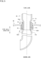
- FIG. 6 is an enlarged sectional view of a connecting portion between a pipe and a vessel body of a pressure vessel according to the third embodiment.
- the first pipe 50 according to the present embodiment is exemplarily applied to the outlet pipe 23 and the inner pipe 25 of the accumulator 16 depicted in FIG. 2 .
- the second end 52b in the pipe axial direction of the second portion 52 depicted in FIG. 6 is connected with a different pipe (second pipe) 55.
- the second pipe 55 has a first end 55a in the pipe axial direction, which is provided with a major diameter portion 55b increased in outer diameter while a stepped portion 55c is interposed therebetween.
- the second end 52b in the pipe axial direction of the second portion 52 is inserted to the major diameter portion 55b of the second pipe 55.
- the outer circumferential surface of the second portion 52 faces an inner circumferential surface of the major diameter portion 55b in the pipe diameter direction.
- the outer circumferential surface of the second portion 52 and the inner circumferential surface of the major diameter portion 55b are brazed to each other.
- the outer circumferential surface of the second portion 52 and the inner circumferential surface of the major diameter portion 55b accordingly interpose a brazed portion 56 made of a brazing material.
- the second pipe 55 is made of iron or the like.
- the second pipe 55 can thus be connected to the second portion 52 made of a material whose main component is copper, by burner brazing with use of the brass brazing material or the like.
- the inner pipe 25 of the vessel body 21 is bent into the U shape. If the inner pipe 25 and the outlet pipe 23 are provided integrally with each other, the inner pipe 25 cannot be substantially attached to the vessel body 21.
- the inner pipe of the vessel body 60 is constituted by the second pipe 55 provided separately from the first pipe 50, so that the first pipe 50 can be attached to the vessel body 60 from outside the vessel body 60 (the upper lid 21b in FIG. 2 ) and the second pipe 55 can be easily attached to the vessel body 60 from inside the vessel body 60 (the upper lid 21b in FIG. 2 ).
- the second pipe 55 may not necessarily be made of iron, and may alternatively be made of a material whose main component is copper. In this case, the second pipe 55 can be connected easily to the second portion 52 by burner brazing or the like.
- the second pipe 55 may still alternatively be made of aluminum, aluminum alloy, or stainless steel. Note that the second pipe 55 made of iron leads to further cost reduction for production of the pressure vessel.
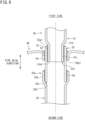
- FIG. 7 is an enlarged sectional view of a connecting portion between a pipe and a vessel body of a pressure vessel according to the fourth embodiment.
- the vessel body 60 of the pressure vessel includes a body 64 and a joint tube 65.
- the body 64 and the joint tube 65 are made of iron.
- the body 64 constitutes a primary part of the vessel body 60 and is configured to contain a refrigerant.
- the body 64 includes a sleeve 64a bent inward.
- the sleeve 64a has an inner circumferential surface constituting an opening 64b.
- the j oint tube 65 is provided to attach the first pipe 50 to the vessel body 60.
- the joint tube 65 has a cylindrical shape.
- the joint tube 65 is inserted to the sleeve 64a.
- the joint tube 65 has an outer circumferential surface facing the inner circumferential surface of the sleeve 64a.
- the j oint tube 65 is attached to the sleeve 64a by welding.
- the j oint tube 65 extends into the body 64 to constitute the inner pipe of the vessel body 60.
- the second portion 52 of the first pipe 50 is connected to the joint tube 65. Specifically, the outer circumferential surface of the second portion 52 is disposed to face an inner circumferential surface of the joint tube 65. The outer circumferential surface of the second portion 52 is brazed to the inner circumferential surface of the joint tube 65 with use of the brass brazing material or the like. The outer circumferential surface of the second portion 52 and the inner circumferential surface of the joint tube 65 accordingly interpose the brazed portion 54.
- the first portion 51 of the first pipe 50 is positioned to be overlapped with the joint tube 65 in the pipe diameter direction.
- the remaining configurations of the first pipe 50 are similar to those according to the first embodiment.
- the body 64 and the joint tube 65 of the vessel body 60 are firmly connected to each other by welding.
- the present embodiment is thus suitably applicable to a pressure vessel required to have high compressive resistance, like a compressor having large capacity (horsepower).
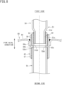
- FIG. 8 is an enlarged sectional view of a connecting portion between a pipe and a vessel body of a pressure vessel according to the fifth embodiment.
- the vessel body 60 includes the body 64 and the joint tube 65.
- the joint tube 65 has a first end in the pipe axial direction, which is connected with the second portion 52 of the first pipe 50.
- the joint tube 65 has a second end in the pipe axial direction, which is connected with a different pipe (third pipe) 70.
- the third pipe 70 is made of a material whose main component is copper (copper or copper alloy).
- the third pipe 70 has an outer circumferential surface facing the inner circumferential surface of the joint tube 65 in the pipe diameter direction.
- the outer circumferential surface of the third pipe 70 and the inner circumferential surface of the joint tube 65 are brazed to each other with use of the brass brazing material or the like.
- the outer circumferential surface of the third pipe 70 and the inner circumferential surface of the joint tube 65 interpose a brazed portion 57.
- the third pipe 70 may not necessarily be made of copper, and may alternatively be made of iron, stainless steel, aluminum, or aluminum alloy.
- the inner circumferential surface of the joint tube 65 is provided with a protrusion 65a projecting radially inward.
- the protrusion 65a is provided continuously along the entire inner circumferential surface of the joint tube 65.
- the protrusion 65a is in contact with the second end surface 52b1 in the pipe axial direction of the second portion 52 of the first pipe 50 inserted to the joint tube 65. This configuration achieves positioning in the pipe axial direction of the first pipe 50 relative to the joint tube 65.
- the protrusion 65a is in contact with a first end surface 70b1 in the pipe axial direction of the third pipe 70 inserted to the joint tube 65. This configuration achieves positioning in the pipe axial direction of the third pipe 70 relative to the joint tube 65.
- the second end surface 52b1 in the pipe axial direction of the second portion 52 of the first pipe 50 is disposed closer to the second side in the pipe axial direction than the second end surface 5 1b 1 in the pipe axial direction of the first portion 51. This disposition achieves reliable contact between the second end surface 52b1 of the second portion 52 and the protrusion 65a. This also prevents any gap between the second portion 52 and the third pipe 70 in the pipe axial direction.
- the second end surface 51b1 of the first portion 51 is disposed closer to the second side in the pipe axial direction than the second end surface 52b1 of the second portion 52, there may be provided a space not including the second portion 52, between the outer circumferential surface of the first portion 51 and the inner circumferential surface of the joint tube 65 in the pipe diameter direction.
- the refrigerant may enter the space to generate unusual sound.
- the pressure vessel according to the present embodiment can avoid such defectiveness.
- the protrusion 65a according to the present embodiment may not necessarily be provided along the entire inner circumferential surface of the joint tube 65, and may alternatively be provided at one circumferential point or at each of a plurality of points circumferentially spaced apart from each other.
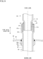
- FIG. 9 is an enlarged sectional view of a connecting portion between a pipe and a vessel body of a pressure vessel according to the sixth embodiment.
- the vessel body 60 includes the body 64 and the joint tube 65.
- the second portion 52 of the first pipe 50 is connected to the joint tube 65.
- the joint tube 65 includes a first portion 66 and a second portion 67.
- the first portion 66 of the joint tube 65 has a cylindrical shape.
- the first portion 66 is inserted to the sleeve 64a of the body 64.
- the first portion 66 is joined to the sleeve 64a by welding.
- the second portion 67 of the joint tube 65 has a cylindrical shape.
- the second portion 67 projects from both ends in the pipe axial direction of the first portion 66 of the joint tube 65.
- the first portion 66 and the second portion 67 of the joint tube 65 are connected to each other by brazing or welding.
- the second portion 67 has a first end in the pipe axial direction, which is provided with a major diameter portion 67a increased in outer diameter while a stepped portion 67b is interposed therebetween.
- the second portion 52 of the first pipe 50 is inserted to the major diameter portion 67a.
- the major diameter portion 67a has an inner circumferential surface, which is connected with the outer circumferential surface of the second portion 52 of the first pipe 50 by brazing or welding.
- the joint tube 65 includes the first portion 66 and the second portion 67, so as to be effective in an exemplary case where the second portion 67 has an outer circumferential surface in a complicated shape inapplicable to a shape of the opening 64b of the body 64.
- the embodiments described above exemplify the accumulator 16 and the compressor 12 as the pressure vessels that are not limited thereto and the examples of which may include the muffler 13 (see FIG. 1 ), the oil separator, and a receiver.
- the receiver is configured to reserve an excessive refrigerant, and is provided on the liquid pipe 10L between the outdoor heat exchanger 14 and the liquid shutoff valve 18L.
Landscapes
- Engineering & Computer Science (AREA)
- General Engineering & Computer Science (AREA)
- Mechanical Engineering (AREA)
- Physics & Mathematics (AREA)
- Thermal Sciences (AREA)
- Chemical & Material Sciences (AREA)
- Analytical Chemistry (AREA)
- Power Engineering (AREA)
- Filling Or Discharging Of Gas Storage Vessels (AREA)
- Pressure Vessels And Lids Thereof (AREA)
- Other Air-Conditioning Systems (AREA)
Description
- The present invention relates to a pressure vessel.
- An air conditioner configured to execute refrigeration cycle operation includes a refrigerant circuit having pressure vessels such as a compressor, an accumulator, and a receiver, and a refrigerant pipe connected to each of the pressure vessels.
Patent Literature 1 discloses adopting a refrigerant pipe made of less expensive stainless steel in place of a refrigerant pipe made of copper exerting excellent processability such as bending and excellent heat conductivity. - The pressure vessels provided on the refrigerant circuit each include a vessel body, an inlet pipe causing a refrigerant to flow into the vessel body, and an outlet pipe causing the refrigerant to flow out of the vessel body. Typically, the vessel body is made of iron whereas the inlet pipe and the outlet pipe are made of copper. Similarly to the refrigerant pipe according to
JP 2010-151327 A - However, the inlet pipe and the outlet pipe made of stainless steel may not be able to be connected with the vessel body made of iron in a manner similar to a conventional method. A pressure vessel and a refrigeration apparatus are also known from
CN 103 983 055 A that describes a vapor-liquid separator input and output structure which comprises a tank, an upper end cover, a stainless steel input pipe and a stainless steel output pipe, wherein the upper end cover covers the end part of the tank and is provided with an inlet, an outlet and flanging parts at the inlet and the outlet, the stainless steel input pipe penetrates through the inlet, the stainless steel output pipe penetrates through the outlet, the outer end of the stainless steel input pipe and the outer end of the stainless steel output pipe are respectively provided with a flaring part, a copper insertion pipe is inserted into each flaring part, and the bottom end of each copper insertion pipe, each flaring part and each flanging part are fixed in a welding manner for forming a five-layer structure consisting of a copper insertion pipe, a first flux layer, a flaring part, a second flux layer and an upper end cover flanging part from inside to outside. Moreover, a pressure vessel and a refrigeration apparatus are also known fromJP H09 112752 A CN 104 588 964 A . - It is an object of the present invention to provide a pressure vessel and a refrigeration apparatus, which allow connection, in a manner similar to the conventional method, between a vessel body and inlet and outlet pipes at least one of which is made of stainless steel.
-
- (1) The present invention provides a pressure vessel according to
claim 1. - According to the above configuration, the inlet pipe and/or the outlet pipe includes the first portion made of stainless steel and the second portion made of a material whose main component is copper, and the second portion is connected to the vessel body. The second portion can thus be connected to the vessel body in a manner similar to a conventional technique for an inlet pipe and/or an outlet pipe made of copper.
- (2) Preferably, the first portion has an outer circumferential surface connected with an inner circumferential surface of the second portion, and
the second portion has an end surface on the second side in the pipe axial direction, the end surface being disposed flush with an end surface on the second side in the pipe axial direction of the first portion, or projecting toward the second side in the pipe axial direction than the end surface of the first portion. - According to this configuration, the first portion does not project toward the second side in the pipe axial direction than the second portion, for reduction in entire size of the inlet pipe and/or the outlet pipe.
- (3) Preferably, a different second pipe is connected to an end on the second side in the pipe axial direction of the second portion.
- (4) Preferably, the vessel body includes a joint tube made of iron, and the second portion is connected to the joint tube.
- (5) Preferably, the second portion is connected to an end on the first side in the pipe axial direction of the joint tube, and
a different third pipe is connected to an end on the second side in the pipe axial direction of the j oint tube. - According to such a configuration, the inlet pipe and/or the outlet pipe and the third pipe disposed in the vessel body can be connected to each other via the joint tube.
- (6) Preferably, the end surface on the second side in the pipe axial direction of the second portion projects toward the second side in the pipe axial direction than the end surface on the second side in the pipe axial direction of the first portion.
- According to this configuration, the second portion and the third pipe connected via the joint tube are less likely to form any gap therebetween, inhibiting entry or the like of the refrigerant into the gap.
- (7) Preferably, the second portion has a portion extending into the vessel body.
- According to such a configuration, the inner pipe disposed in the vessel body can be constituted by the second portion thus extended, achieving reduction in the number of components of the pipe.
- (8) Preferably, the end on the second side in the pipe axial direction of the first portion is provided with a minor diameter portion reduced in outer diameter, and
the minor diameter portion has an outer circumferential surface connected to the inner circumferential surface of the second portion. - According to such a configuration, the minor diameter portion of the first portion is inserted to the second portion and the end of the second portion is made in contact with a portion around a proximal end of the minor diameter portion, for positioning in the pipe axial direction of the first portion and the second portion.
- (9) Preferably, the first portion has a portion overlapped with the vessel body in a pipe diameter direction.
- According to this configuration, the first portion stronger than the second portion is overlapped with the vessel body in the pipe diameter direction, for improvement in connection strength between the vessel body and the inlet pipe and/or the outlet pipe.
- (10) Preferably, the end on the first side in the pipe axial direction of the first portion is provided with a plated portion made of a material whose main component is copper or a tube made of a material whose main component is copper.
- According to this configuration, a refrigerant pipe made of copper can be connected easily to the end of the first portion made of stainless steel, with use of an inexpensive brazing material.
- (11) The present invention provides a refrigeration apparatus including the pressure vessel according to any one of (1) to (10) described above.
-
-
FIG. 1 is a schematic configuration diagram of a refrigeration apparatus including a pressure vessel according to a first embodiment of the present invention. -
FIG. 2 is a front view (partially sectional view) of an exemplary pressure vessel. -
FIG. 3 is a perspective view of another exemplary pressure vessel. -
FIG. 4 is an enlarged sectional view of a connecting portion between a pipe and a vessel body of the pressure vessel. -
FIG. 5 is an enlarged sectional view of a connecting portion between a pipe and a vessel body of a pressure vessel according to a second embodiment. -
FIG. 6 is an enlarged sectional view of a connecting portion between a pipe and a vessel body of a pressure vessel according to a third embodiment. -
FIG. 7 is an enlarged sectional view of a connecting portion between a pipe and a vessel body of a pressure vessel according to a fourth embodiment. -
FIG. 8 is an enlarged sectional view of a connecting portion between a pipe and a vessel body of a pressure vessel according to a fifth embodiment. -
FIG. 9 is an enlarged sectional view of a connecting portion between a pipe and a vessel body of a pressure vessel according to a sixth embodiment. - Embodiments of the present invention will be described in detail hereinafter with reference to the accompanying drawings.
- Description will be made hereinafter to embodiments of the present invention with reference to the drawings.
-
FIG. 1 is a schematic configuration diagram of a refrigeration apparatus including a pressure vessel according to the first embodiment of the present invention. - A
refrigeration apparatus 1 exemplifies an air conditioner configured to condition indoor temperature and indoor humidity, and includes anoutdoor unit 2 disposed outdoors and anindoor unit 3 disposed indoors. Theoutdoor unit 2 and theindoor unit 3 are connected to each other via arefrigerant pipe 10. - The
refrigeration apparatus 1 includes arefrigerant circuit 4 configured to execute vapor compression refrigeration cycle operation. Therefrigerant circuit 4 includes a plurality of element components and therefrigerant pipe 10 connecting the plurality of element components. Therefrigerant circuit 4 includes, as the element components, anindoor heat exchanger 11, acompressor 12, amuffler 13, anoutdoor heat exchanger 14, anexpansion mechanism 15, anaccumulator 16, a four-way switching valve (switching mechanism) 17, and the like, which are connected via therefrigerant pipe 10. Therefrigerant pipe 10 includes aliquid pipe 10L and agas pipe 10G. Theliquid pipe 10L and thegas pipe 10G are provided with aliquid shutoff valve 18L and agas shutoff valve 18G, respectively. - The
indoor heat exchanger 11 is provided in theindoor unit 3 and executes heat exchange between a refrigerant and indoor air. Examples of theindoor heat exchanger 11 include a fin-and-tube heat exchanger of a cross-fin type and a heat exchanger of a microchannel type. Theindoor heat exchanger 11 is provided therearound with an indoor fan (not depicted) configured to send indoor air to theindoor heat exchanger 11 and send conditioned air to indoors. - The
compressor 12, themuffler 13, theoutdoor heat exchanger 14, theexpansion mechanism 15, theaccumulator 16, and the four-way switching valve 17 are provided in theoutdoor unit 2. Thecompressor 12 is configured to compress a refrigerant sucked from an inlet pipe and discharge the compressed refrigerant from an outlet pipe. Examples of thecompressor 12 include various compressors such as a scroll compressor. - The
muffler 13 inhibits pressure pulsation of the refrigerant discharged from thecompressor 12. The outlet pipe of thecompressor 12 and the four-way switching valve 17 may interpose an oil separator in place of or in addition to themuffler 13. The oil separator is configured to separate lubricant from fluid mixture that contains the lubricant and a refrigerant and is discharged from thecompressor 12. - The
outdoor heat exchanger 14 executes heat exchange between the refrigerant and outdoor air. Examples of theoutdoor heat exchanger 14 include a fin-and-tube heat exchanger of a cross-fin type and a heat exchanger of a microchannel type. Theoutdoor heat exchanger 14 is provided therearound with an outdoor fan configured to send outdoor air to theoutdoor heat exchanger 14. - The
expansion mechanism 15 is disposed between theoutdoor heat exchanger 14 and theindoor heat exchanger 11 on therefrigerant pipe 10 of therefrigerant circuit 4, and expands the incoming refrigerant to be decompressed to have predetermined pressure. Examples of theexpansion mechanism 15 include an electronic expansion valve having a variable opening degree, and a capillary tube. - The
accumulator 16 is disposed between a suction port of thecompressor 12 and the four-way switching valve 17 in therefrigerant circuit 4, and is configured to separate the incoming refrigerant into a gas refrigerant and a liquid refrigerant. The gas refrigerant thus separated by theaccumulator 16 is sucked into thecompressor 12. - The four-
way switching valve 17 is configured to be switchable between a first state indicated by a solid line and a second state indicated by a broken line inFIG. 1 . The four-way switching valve 17 is switched into the first state while theair conditioner 1 executes cooling operation, and the four-way switching valve 17 is switched into the second state while theair conditioner 1 executes heating operation. -
FIG. 2 is a front view (partially sectional view) of an exemplary pressure vessel according to the first embodiment of the present invention.FIG. 3 is a perspective view of another exemplary pressure vessel. - The pressure vessel depicted in
FIG. 2 is theaccumulator 16. Theaccumulator 16 includes avessel body 21, aninlet pipe 22, and anoutlet pipe 23. Thevessel body 21 constitutes a primary part of theaccumulator 16 and is configured to contain a refrigerant. Thevessel body 21 includes atrunk 21a having a cylindrical shape, and twolids trunk 21a. - The present specification will also refer to an axial direction including a center in a transverse section of a pipe such as the
inlet pipe 22 or theoutlet pipe 23, as a "pipe axial direction". A radial direction of a pipe perpendicular to the pipe axial direction will also be called a "pipe diameter direction". An end or an end surface on a first side in the pipe axial direction of the pipe will also be called a "first end" or a "first end surface", and an end or an end surface on a second side in the pipe axial direction will also be called a "second end" or a "second end surface". Each of the "first end" and the "second end" in the pipe axial direction of the pipe refers to a region positioned at an end in the pipe axial direction of the pipe, such as a region adjacent to the "first end surface" or the "second end surface", and may not necessarily include the "first end surface" or the "second end surface" in the pipe axial direction. - The
inlet pipe 22 is provided on an upper part of the vessel body 21 (theupper lid 21b). Theinlet pipe 22 has a first end (upper end) in the pipe axial direction, which projects from thevessel body 21. The first end of theinlet pipe 22 is connected to the four-way switching valve 17 (seeFIG. 1 ) via therefrigerant pipe 10. Theinlet pipe 22 has a second end (lower end) in the pipe axial direction, which is disposed in thevessel body 21. - The
outlet pipe 23 is disposed on the upper part of the vessel body 21 (upper lid 21b) and adjacent to theinlet pipe 22. Theoutlet pipe 23 has a first end (upper end) in the pipe axial direction, which projects from thevessel body 21. The first end of theoutlet pipe 23 is connected to the compressor 12 (seeFIG. 1 ) via therefrigerant pipe 10. Theoutlet pipe 23 has a second end (lower end) in the pipe axial direction, which is disposed in thevessel body 21. - The
accumulator 16 includes twoinner pipes vessel body 21. Theinner pipe 24 extends downward from the second end of theinlet pipe 22. Theinner pipe 25 extends downward from the second end of theoutlet pipe 23, is bent upward into a U shape in a lower part of thevessel body 21, and extends into the upper part of thevessel body 21. - The pressure vessel depicted in
FIG. 3 is thecompressor 12. Thecompressor 12 includes avessel body 27, an inlet pipe 28, anoutlet pipe 29, and an injection pipe 30. Thevessel body 27 constitutes a primary part of thecompressor 12 and is configured to contain a refrigerant. Thevessel body 27 accommodates a motor, a compression mechanism, and the like. Thevessel body 27 includes atrunk 27a having a cylindrical shape, andlids trunk 27a. - The inlet pipe 28 is provided on an upper part of the vessel body 27 (the
upper lid 27b). The inlet pipe 28 has a first end (upper end) in the pipe axial direction, which projects from thevessel body 27. The first end of the inlet pipe 28 is connected to the accumulator 16 (seeFIG. 1 ) via therefrigerant pipe 10. The inlet pipe 28 has a second end in the pipe axial direction, which is disposed in thevessel body 27. - The
outlet pipe 29 is provided halfway (on thetrunk 27a) in a vertical direction of thevessel body 27. Theoutlet pipe 29 has a first end in the pipe axial direction, which projects from thevessel body 27. The first end of theoutlet pipe 29 is connected to the muffler 13 (seeFIG. 1 ) via therefrigerant pipe 10. Theoutlet pipe 29 has a second end in the pipe axial direction, which is disposed in thevessel body 27. - The injection pipe 30 is provided on the upper part of the vessel body 27 (the
upper lid 27b). The injection pipe 30 causes an intermediate pressure refrigerant to flow from a subcooler or the like (not depicted) into thevessel body 27. The injection pipe 30 is accordingly one kind of the inlet pipe 28. The injection pipe 30 has a first end in the pipe axial direction, which projects from thevessel body 27. The injection pipe 30 has a second end in the pipe axial direction, which is disposed in thevessel body 27. - The
inlet pipes 22 and 28 (including the injection pipe 30) and theoutlet pipes accumulator 16 and thecompressor 12 are structured as described below. In the following description, theinlet pipes 22, 28, and 30 and theoutlet pipes reference sign 50. Thevessel bodies reference sign 60 without distinction among theaccumulator 16, thecompressor 12, and the like. -
FIG. 4 is an enlarged sectional view of a connecting portion between a pipe and the vessel body of the pressure vessel. - A
vessel body 60 is made of iron. Thevessel body 60 is provided with anopening 61 configured to receive thefirst pipe 50. Theopening 61 is constituted by an inner circumferential surface of asleeve 62 bent toward inside thevessel body 60 to have a cylindrical shape. Thesleeve 62 may alternatively be bent toward outside thevessel body 60 to have a cylindrical shape. Thesleeve 62 may exemplarily be formed by burring. - The
first pipe 50 includes afirst portion 51 and asecond portion 52. Thefirst portion 51 is made of stainless steel. Thefirst portion 51 is made of SUS304, SUS304L, SUS436L, SUS430, or the like. Thefirst portion 51 has afirst end 51a in the pipe axial direction, which is disposed outside thevessel body 60. Thefirst portion 51 has asecond end 51b in the pipe axial direction, at least part of which is disposed in thevessel body 60 and is connected to thesecond portion 52. - The
second end 51b of thefirst portion 51 is provided with aminor diameter portion 51c reduced in outer diameter, while a steppedportion 51d is interposed therebetween. Thefirst end 51a of thefirst portion 51 is provided with amajor diameter portion 51e increased in outer diameter, while a steppedportion 51f is interposed therebetween. Themajor diameter portion 51e has an inner circumferential surface provided with a platedportion 51g made of a material whose main component is copper. Arefrigerant pipe 20 made of a material whose main component is copper is brazed with use of a phosphor copper brazing material or the like to the platedportion 51g. - The
second portion 52 is made of copper or copper alloy, which is a material whose main component is copper. Thesecond portion 52 has a cylindrical shape. Thesecond portion 52 has an inner circumference into which theminor diameter portion 51c of thefirst portion 51 is inserted. Thesecond portion 52 has an inner circumferential surface facing an outer circumferential surface of theminor diameter portion 51c of thefirst portion 51 in the pipe diameter direction. The inner circumferential surface of thesecond portion 52 and the outer circumferential surface of theminor diameter portion 51c of thefirst portion 51 are brazed to each other. The inner circumferential surface of thesecond portion 52 and the outer circumferential surface of theminor diameter portion 51c accordingly interpose a brazedportion 53 made of a brazing material. - The
second portion 52 is restricted from moving toward the first side in the pipe axial direction relatively to thefirst portion 51 to be positioned, by the steppedportion 51d positioned at a proximal end of theminor diameter portion 51c. Thesecond portion 52 has a second end surface 52b1 in the pipe axial direction, which is disposed closer to the second side in the pipe axial direction (lower side inFIG. 4 ) than a second end surface 51b1 in the pipe axial direction of thefirst portion 51. - The
second portion 52 is inserted to thesleeve 62 of thevessel body 60 and is fixed to thesleeve 62. Specifically, thesecond portion 52 has an outer circumferential surface disposed to face the inner circumferential surface of thesleeve 62 of thevessel body 60 in the pipe diameter direction. The outer circumferential surface of thesecond portion 52 and the inner circumferential surface of thesleeve 62 are brazed to each other. The outer circumferential surface of thesecond portion 52 and the inner circumferential surface of thesleeve 62 accordingly interpose a brazedportion 54 made of a brazing material. - The
second portion 52 and thesleeve 62 are connected to each other by brazing with use of a brass brazing material. Typical examples of such brazing include burner brazing. The burner brazing is different from "furnace brazing" and is executed manually or with use of a brazing device including a burner. - A conventional pressure vessel includes inlet and outlet pipes made of copper (hereinafter, also called the "inlet pipe and the like") and brazed with use of the brass brazing material to the
vessel body 60 made of iron. If the inlet pipe and the like are entirely made of stainless steel, connection of the inlet pipe and the like to thevessel body 60 made of iron needs a silver brazing material that is more expensive than the brass brazing material. According to the present embodiment, thefirst pipe 50 includes thefirst portion 51 made of stainless steel and thesecond portion 52 made of a material whose main component is copper (made of copper or copper alloy), and thesecond portion 52 is connected to thevessel body 60. Accordingly, similarly to the conventional pressure vessel, thefirst pipe 50 including thefirst portion 51 made of stainless steel can be connected to thevessel body 60 by brazing with use of the brass brazing material. - The
second portion 52 has a first end surface 52a1 in the pipe axial direction, which is disposed closer to the first side in the pipe axial direction (upper side inFIG. 4 ) than a first end in the pipe axial direction, of thesleeve 62 of thevessel body 60. The second end surface 52b1 in the pipe axial direction of thesecond portion 52 is disposed closer to the second side in the pipe axial direction (lower side inFIG. 4 ) than a second end surface 62b1 in the pipe axial direction of thesleeve 62 of thevessel body 60. Thesecond portion 52 accordingly projects from both ends in the pipe axial direction of thesleeve 62. - The second end surface 51b1 in the pipe axial direction of the
first portion 51 is disposed closer to the second side in the pipe axial direction (lower side inFIG. 4 ) than a second end surface 62b1 in the pipe axial direction of thesleeve 62 of thevessel body 60. Theminor diameter portion 51c of thefirst portion 51 is disposed to be overlapped with thesleeve 62 of thevessel body 60 in the pipe diameter direction. Specifically, theminor diameter portion 51c of thefirst portion 51 is overlapped in the pipe diameter direction with entire length L1 in the pipe axial direction of thesleeve 62 of thevessel body 60. - The
first portion 51 and thesecond portion 52 of thefirst pipe 50 are connected by furnace brazing and are placed in a high-temperature environment in a furnace. Thesecond portion 52 made of copper may thus have coarsened copper crystal grains to cause strength deterioration. According to the present embodiment, thefirst portion 51 made of stainless steel and thevessel body 60 made of iron are disposed to be overlapped with each other in the pipe diameter direction. Thesecond portion 52 is not provided by itself where thevessel body 60 and thefirst pipe 50 are connected to each other, and thesecond portion 52 is overlapped with at least one of thevessel body 60 and thefirst portion 51 in the pipe diameter direction. Strength deterioration of thesecond portion 52 is accordingly compensated with thevessel body 60 and thefirst portion 51. - The second end surface 51b1 of the
first portion 51 is disposed closer to the first side in the pipe axial direction than the second end surface 52b1 of thesecond portion 52. Thefirst pipe 50 can thus be reduced in entire length in comparison to another case where the second end surface 51b1 of thefirst portion 51 is disposed closer to the second side in the pipe axial direction than the second end surface 52b1 of thesecond portion 52, in other words, a case where thesecond end 51b of thefirst portion 51 projects toward the second side in the pipe axial direction than asecond end 52b of thesecond portion 52. This enables increase in the number offirst pipes 50 simultaneously provided in the furnace for furnace brazing between thefirst portion 51 and thesecond portion 52 of each of thefirst pipes 50, which achieves improvement in production efficiency of thefirst pipes 50. The second end surface 51b1 of thefirst portion 51 and the second end surface 52b1 of thesecond portion 52 may alternatively be disposed flush with each other. - The
second portion 52 may alternatively be provided at thesecond end 51b of thefirst portion 51 in a state where the second end surface 52b1 is disposed closer to the first side in the pipe axial direction (upper side inFIG. 4 ) than the second end surface 51b1 of thefirst portion 51, though functional effects described above will not be achieved in this case. -
FIG. 5 is an enlarged sectional view of a connecting portion between a pipe and a vessel body of a pressure vessel according to the second embodiment. - The
first pipe 50 according to the present embodiment is exemplarily applied to theinlet pipe 22 and theinner pipe 24 of theaccumulator 16 depicted inFIG. 2 . Thesecond portion 52 of thefirst pipe 50 depicted inFIG. 5 is extended into thevessel body 60 than thesecond portion 52 of thefirst pipe 50 depicted inFIG. 4 . In other words, thefirst pipe 50 projecting outward from thevessel body 60 also serves as an inner pipe of thevessel body 60. The present embodiment can thus achieve reduction in the number of constituent elements of the pressure vessel in comparison to a case where a different inner pipe is connected to thefirst pipe 50, for reduction in the number of components and cost reduction. The remaining configurations of thefirst pipe 50 are same as those according to the first embodiment. -
FIG. 6 is an enlarged sectional view of a connecting portion between a pipe and a vessel body of a pressure vessel according to the third embodiment. - The
first pipe 50 according to the present embodiment is exemplarily applied to theoutlet pipe 23 and theinner pipe 25 of theaccumulator 16 depicted inFIG. 2 . Thesecond end 52b in the pipe axial direction of thesecond portion 52 depicted inFIG. 6 is connected with a different pipe (second pipe) 55. Thesecond pipe 55 has afirst end 55a in the pipe axial direction, which is provided with amajor diameter portion 55b increased in outer diameter while a steppedportion 55c is interposed therebetween. Thesecond end 52b in the pipe axial direction of thesecond portion 52 is inserted to themajor diameter portion 55b of thesecond pipe 55. The outer circumferential surface of thesecond portion 52 faces an inner circumferential surface of themajor diameter portion 55b in the pipe diameter direction. The outer circumferential surface of thesecond portion 52 and the inner circumferential surface of themajor diameter portion 55b are brazed to each other. The outer circumferential surface of thesecond portion 52 and the inner circumferential surface of themajor diameter portion 55b accordingly interpose a brazedportion 56 made of a brazing material. - The
second pipe 55 is made of iron or the like. Thesecond pipe 55 can thus be connected to thesecond portion 52 made of a material whose main component is copper, by burner brazing with use of the brass brazing material or the like. As depicted inFIG. 2 , theinner pipe 25 of thevessel body 21 is bent into the U shape. If theinner pipe 25 and theoutlet pipe 23 are provided integrally with each other, theinner pipe 25 cannot be substantially attached to thevessel body 21. According to the present embodiment as depicted inFIG. 6 , the inner pipe of thevessel body 60 is constituted by thesecond pipe 55 provided separately from thefirst pipe 50, so that thefirst pipe 50 can be attached to thevessel body 60 from outside the vessel body 60 (theupper lid 21b inFIG. 2 ) and thesecond pipe 55 can be easily attached to thevessel body 60 from inside the vessel body 60 (theupper lid 21b inFIG. 2 ). - The
second pipe 55 may not necessarily be made of iron, and may alternatively be made of a material whose main component is copper. In this case, thesecond pipe 55 can be connected easily to thesecond portion 52 by burner brazing or the like. Thesecond pipe 55 may still alternatively be made of aluminum, aluminum alloy, or stainless steel. Note that thesecond pipe 55 made of iron leads to further cost reduction for production of the pressure vessel. -
FIG. 7 is an enlarged sectional view of a connecting portion between a pipe and a vessel body of a pressure vessel according to the fourth embodiment. - The
vessel body 60 of the pressure vessel according to the present embodiment includes abody 64 and ajoint tube 65. Thebody 64 and thejoint tube 65 are made of iron. Thebody 64 constitutes a primary part of thevessel body 60 and is configured to contain a refrigerant. Thebody 64 includes asleeve 64a bent inward. Thesleeve 64a has an inner circumferential surface constituting anopening 64b. - The j oint
tube 65 is provided to attach thefirst pipe 50 to thevessel body 60. Thejoint tube 65 has a cylindrical shape. Thejoint tube 65 is inserted to thesleeve 64a. Thejoint tube 65 has an outer circumferential surface facing the inner circumferential surface of thesleeve 64a. The j ointtube 65 is attached to thesleeve 64a by welding. The j ointtube 65 extends into thebody 64 to constitute the inner pipe of thevessel body 60. - The
second portion 52 of thefirst pipe 50 is connected to thejoint tube 65. Specifically, the outer circumferential surface of thesecond portion 52 is disposed to face an inner circumferential surface of thejoint tube 65. The outer circumferential surface of thesecond portion 52 is brazed to the inner circumferential surface of thejoint tube 65 with use of the brass brazing material or the like. The outer circumferential surface of thesecond portion 52 and the inner circumferential surface of thejoint tube 65 accordingly interpose the brazedportion 54. Thefirst portion 51 of thefirst pipe 50 is positioned to be overlapped with thejoint tube 65 in the pipe diameter direction. The remaining configurations of thefirst pipe 50 are similar to those according to the first embodiment. - According to the present embodiment, the
body 64 and thejoint tube 65 of thevessel body 60 are firmly connected to each other by welding. The present embodiment is thus suitably applicable to a pressure vessel required to have high compressive resistance, like a compressor having large capacity (horsepower). -
FIG. 8 is an enlarged sectional view of a connecting portion between a pipe and a vessel body of a pressure vessel according to the fifth embodiment. - As in the fourth embodiment, the
vessel body 60 according to the present embodiment includes thebody 64 and thejoint tube 65. Thejoint tube 65 has a first end in the pipe axial direction, which is connected with thesecond portion 52 of thefirst pipe 50. Thejoint tube 65 has a second end in the pipe axial direction, which is connected with a different pipe (third pipe) 70. - The
third pipe 70 is made of a material whose main component is copper (copper or copper alloy). Thethird pipe 70 has an outer circumferential surface facing the inner circumferential surface of thejoint tube 65 in the pipe diameter direction. The outer circumferential surface of thethird pipe 70 and the inner circumferential surface of thejoint tube 65 are brazed to each other with use of the brass brazing material or the like. The outer circumferential surface of thethird pipe 70 and the inner circumferential surface of thejoint tube 65 interpose a brazedportion 57. Thethird pipe 70 may not necessarily be made of copper, and may alternatively be made of iron, stainless steel, aluminum, or aluminum alloy. - The inner circumferential surface of the
joint tube 65 is provided with aprotrusion 65a projecting radially inward. Theprotrusion 65a is provided continuously along the entire inner circumferential surface of thejoint tube 65. Theprotrusion 65a is in contact with the second end surface 52b1 in the pipe axial direction of thesecond portion 52 of thefirst pipe 50 inserted to thejoint tube 65. This configuration achieves positioning in the pipe axial direction of thefirst pipe 50 relative to thejoint tube 65. - The
protrusion 65a is in contact with a first end surface 70b1 in the pipe axial direction of thethird pipe 70 inserted to thejoint tube 65. This configuration achieves positioning in the pipe axial direction of thethird pipe 70 relative to thejoint tube 65. - The second end surface 52b1 in the pipe axial direction of the
second portion 52 of thefirst pipe 50 is disposed closer to the second side in the pipe axial direction than the second end surface 51b 1 in the pipe axial direction of thefirst portion 51. This disposition achieves reliable contact between the second end surface 52b1 of thesecond portion 52 and theprotrusion 65a. This also prevents any gap between thesecond portion 52 and thethird pipe 70 in the pipe axial direction. If the second end surface 51b1 of thefirst portion 51 is disposed closer to the second side in the pipe axial direction than the second end surface 52b1 of thesecond portion 52, there may be provided a space not including thesecond portion 52, between the outer circumferential surface of thefirst portion 51 and the inner circumferential surface of thejoint tube 65 in the pipe diameter direction. In such a case, the refrigerant may enter the space to generate unusual sound. The pressure vessel according to the present embodiment can avoid such defectiveness. - The
protrusion 65a according to the present embodiment may not necessarily be provided along the entire inner circumferential surface of thejoint tube 65, and may alternatively be provided at one circumferential point or at each of a plurality of points circumferentially spaced apart from each other. -
FIG. 9 is an enlarged sectional view of a connecting portion between a pipe and a vessel body of a pressure vessel according to the sixth embodiment. - As in the fourth embodiment, the
vessel body 60 according to the present embodiment includes thebody 64 and thejoint tube 65. Thesecond portion 52 of thefirst pipe 50 is connected to thejoint tube 65. Thejoint tube 65 includes afirst portion 66 and asecond portion 67. Thefirst portion 66 of thejoint tube 65 has a cylindrical shape. Thefirst portion 66 is inserted to thesleeve 64a of thebody 64. Thefirst portion 66 is joined to thesleeve 64a by welding. - The
second portion 67 of thejoint tube 65 has a cylindrical shape. Thesecond portion 67 projects from both ends in the pipe axial direction of thefirst portion 66 of thejoint tube 65. Thefirst portion 66 and thesecond portion 67 of thejoint tube 65 are connected to each other by brazing or welding. Thesecond portion 67 has a first end in the pipe axial direction, which is provided with amajor diameter portion 67a increased in outer diameter while a steppedportion 67b is interposed therebetween. Thesecond portion 52 of thefirst pipe 50 is inserted to themajor diameter portion 67a. Themajor diameter portion 67a has an inner circumferential surface, which is connected with the outer circumferential surface of thesecond portion 52 of thefirst pipe 50 by brazing or welding. - The
joint tube 65 according to the present embodiment includes thefirst portion 66 and thesecond portion 67, so as to be effective in an exemplary case where thesecond portion 67 has an outer circumferential surface in a complicated shape inapplicable to a shape of theopening 64b of thebody 64. - The embodiments described above exemplify the
accumulator 16 and thecompressor 12 as the pressure vessels that are not limited thereto and the examples of which may include the muffler 13 (seeFIG. 1 ), the oil separator, and a receiver. The receiver is configured to reserve an excessive refrigerant, and is provided on theliquid pipe 10L between theoutdoor heat exchanger 14 and theliquid shutoff valve 18L. -
- (1) As depicted in
FIG. 2 andFIG. 3 , the pressure vessel according to each of the above embodiments includes thevessel body inlet pipe 22 or 28 causing the refrigerant to flow into thevessel body outlet pipe vessel body FIG. 4 , thefirst pipe 50 serving as at least one of theinlet pipe 22 or 28 and theoutlet pipe first portion 51 made of stainless steel, thesecond portion 52 made of a material whose main component is copper, and the brazedportion 53 connecting thefirst portion 51 and thesecond portion 52. Thefirst end 51a of thefirst portion 51 in the pipe axial direction of thefirst pipe 50 is disposed outside thevessel body 60. Thesecond end 51b of thefirst portion 51 in the pipe axial direction of thefirst pipe 50 is connected to thesecond portion 52. Thesecond portion 52 is connected to thevessel body 60.
In the above configuration, the first pipe 50 (theinlet pipe 22 or 28 and/or theoutlet pipe 23 or 29) includes thefirst portion 51 made of stainless steel and thesecond portion 52 made of a material whose main component is copper, and thesecond portion 52 is connected to thevessel body 60. Thesecond portion 52 can thus be connected to thevessel body 60 in a manner similar to the conventional technique for thefirst pipe 50 made of copper. Thefirst pipe 50 mostly made of inexpensive stainless steel can accordingly be connected easily to thevessel body 60 as in the conventional technique. - (2) In the
first pipe 50 according to each of the above embodiments, the outer circumferential surface of thefirst portion 51 and the inner circumferential surface of thesecond portion 52 are connected to each other, the second end surface 52b1 in the pipe axial direction of thesecond portion 52 is disposed flush with the second end surface 51b1 in the pipe axial direction of thefirst portion 51 or projects toward the second side in the pipe axial direction than the second end surface 51b1 of thefirst portion 51. In this case, thefirst portion 51 does not project toward the second side in the pipe axial direction than thesecond portion 52, which leads to reduction in entire size of thefirst pipe 50. When thefirst portion 51 and thesecond portion 52 are furnace brazed to each other, a larger number offirst pipes 50 can be brazed simultaneously for improvement in production efficiency. - (3) According to the third embodiment (see
FIG. 6 ), the differentsecond pipe 55 is connected to thesecond end 52b in the pipe axial direction of thesecond portion 52 of thefirst pipe 50. Thesecond pipe 55, which may be bent into a U shape or the like, can accordingly be disposed easily in thevessel body 60. - (4) The
vessel body 60 according to each of the fourth to sixth embodiments (seeFIG. 7 to FIG. 9 ) includes thejoint tube 65 made of iron and connected with thesecond portion 52. With thevessel body 60 including thejoint tube 65 made of iron, a piping portion (the joint tube 65) can be connected firmly to the primary part (the body 64) of thevessel body 60, for higher compressive resistance and easy connection with thefirst pipe 50. - (5) In the fifth embodiment (see
FIG. 8 ), thesecond portion 52 is connected to the first end in the pipe axial direction of thejoint tube 65, and the differentthird pipe 70 is connected to the second end in the pipe axial direction of thejoint tube 65. Thefirst pipe 50 and thethird pipe 70 disposed in thevessel body 60 can thus be connected to each other via thejoint tube 65. - (6) In the fifth embodiment (see
FIG. 8 ), the second end surface 52b1 in the pipe axial direction of thesecond portion 52 of thefirst pipe 50 projects toward the second side in the pipe axial direction than the second end surface 51b1 in the pipe axial direction of thefirst portion 51 of thefirst pipe 50. Thesecond portion 52 and thethird pipe 70 connected via thejoint tube 65 are less likely to form any gap therebetween, inhibiting entry or the like of the refrigerant into the gap. - (7) In the second embodiment (see
FIG. 5 ), thesecond portion 52 of thefirst pipe 50 has a portion extending into thevessel body 60. Accordingly, the inner pipe disposed in thevessel body 60 can be constituted by thesecond portion 52 thus extended, achieving reduction in the number of components of thefirst pipe 50 in comparison to the case where the inner pipe is constituted by a pipe provided separately from thefirst pipe 50. - (8) In the
first portion 51 of thefirst pipe 50 according to each of the above embodiments, the second end in the pipe axial direction is provided with theminor diameter portion 51c reduced in outer diameter, and the outer circumferential surface of theminor diameter portion 51c is connected to the inner circumferential surface of thesecond portion 52 of thefirst pipe 50. Accordingly, theminor diameter portion 51c of thefirst portion 51 is inserted to thesecond portion 52 and the proximal end of theminor diameter portion 51c is made in contact with the end of thesecond portion 52, for positioning in the pipe axial direction between thefirst portion 51 and thesecond portion 52. - (9) The
first portion 51 of thefirst pipe 50 according to each of the above embodiments has a portion overlapped with thevessel body 60 in the pipe diameter direction. When thefirst portion 51 of thefirst pipe 50 is overlapped with the vessel body 60 (thesleeve 62 or the joint tube 65) in the pipe diameter direction, thesecond portion 52 is not provided by itself, for improvement in connection strength between thevessel body 60 and thefirst pipe 50. - (10) In each of the above embodiments, the first end in the pipe axial direction of the
first portion 51 of thefirst pipe 50 is provided with a plated portion made of a material whose main component is copper or a tube made of a material whose main component is copper. A refrigerant pipe made of copper can thus be connected easily to the end of thefirst portion 51 made of stainless steel, with use of an inexpensive brazing material. -
- 1
- refrigeration apparatus
- 4
- refrigerant circuit
- 21
- vessel body
- 22
- inlet pipe
- 23
- outlet pipe
- 27
- vessel body
- 28
- inlet pipe
- 29
- outlet pipe
- 30
- injection pipe
- 50
- first pipe
- 51
- first portion
- 51a
- first end
- 51b
- second end
- 51b1
- second end surface
- 51c
- minor diameter portion
- 52
- second portion
- 52b
- second end
- 52b1
- second end surface
- 53
- brazed portion
- 55
- second pipe
- 60
- vessel body
- 65
- joint tube
- 70
- third pipe
Claims (11)
- A pressure vessel providable on a refrigerant circuit (4),the pressure vessel comprising a vessel body (60) made of iron, an inlet pipe causing a refrigerant to flow into the vessel body (60), and an outlet pipe causing the refrigerant to flow out of the vessel body (60), whereina pipe (50) corresponding to at least one of the inlet pipe and the outlet pipe includes a first portion (51) made of stainless steel, a second portion (52) made of a material whose main component is copper, and a brazed portion (53) connecting the first portion (51) and the second portion (52),the first portion (51) has an end (51a) on a first side in a pipe axial direction of the pipe (50), the end (51a) being disposed outside the vessel body (60),the first portion (51) has an end (51b) on a second side in the pipe axial direction, the end (51b) being connected to the second portion (52), andthe second portion (52) is connected to the vessel body (60).
- The pressure vessel according to claim 1, whereinthe first portion (51) has an outer circumferential surface connected with an inner circumferential surface of the second portion (52), andthe second portion (52) has an end surface (52b1) on the second side in the pipe axial direction, the end surface (52b1) being disposed flush with an end surface (51b1) on the second side in the pipe axial direction of the first portion (51), or projecting toward the second side in the pipe axial direction than the end surface (51b1) of the first portion (51).
- The pressure vessel according to claim 1 or 2, wherein a different second pipe (55) is connected to an end (52b) on the second side in the pipe axial direction of the second portion (52).
- The pressure vessel according to any one of claims 1 to 3, whereinthe vessel body (60) includes a joint tube (65) made of iron, andthe second portion (52) is connected to the joint tube (65).
- The pressure vessel according to claim 4, whereinthe second portion (52) is connected to an end on the first side in the pipe axial direction of the joint tube (65), anda different third pipe (70) is connected to an end on the second side in the pipe axial direction of the joint tube (65).
- The pressure vessel according to claim 5, wherein the end surface (52b1) on the second side in the pipe axial direction of the second portion (52) projects toward the second side in the pipe axial direction than the end surface (51b1) on the second side in the pipe axial direction of the first portion (51).
- The pressure vessel according to any one of claims 1 to 6, wherein the second portion (52) has a portion extending into the vessel body (60).
- The pressure vessel according to any one of claims 1 to 7, whereinthe end (51b) on the second side in the pipe axial direction of the first portion (51) is provided with a minor diameter portion (5 1c) reduced in outer diameter, andthe minor diameter portion (5 1c) has an outer circumferential surface connected to the inner circumferential surface of the second portion (52).
- The pressure vessel according to any one of claims 1 to 8, wherein the first portion (51) has a portion overlapped with the vessel body (60) in a pipe diameter direction.
- The pressure vessel according to any one of claims 1 to 9, wherein the end (5 1a) on the first side in the pipe axial direction of the first portion (51) is provided with a plated portion (51g) made of a material whose main component is copper or a tube made of a material whose main component is copper.
- A refrigeration apparatus comprising the pressure vessel according to any one of claims 1 to 10.
Applications Claiming Priority (2)
| Application Number | Priority Date | Filing Date | Title |
|---|---|---|---|
| JP2020088945A JP6879408B1 (en) | 2020-05-21 | 2020-05-21 | Pressure vessel and refrigeration equipment |
| PCT/JP2021/001971 WO2021234999A1 (en) | 2020-05-21 | 2021-01-21 | Pressure vessel and refrigeration device |
Publications (3)
| Publication Number | Publication Date |
|---|---|
| EP4155586A1 EP4155586A1 (en) | 2023-03-29 |
| EP4155586A4 EP4155586A4 (en) | 2023-12-20 |
| EP4155586B1 true EP4155586B1 (en) | 2025-02-26 |
Family
ID=76083808
Family Applications (1)
| Application Number | Title | Priority Date | Filing Date |
|---|---|---|---|
| EP21809088.4A Active EP4155586B1 (en) | 2020-05-21 | 2021-01-21 | Pressure vessel and refrigeration device |
Country Status (6)
| Country | Link |
|---|---|
| US (2) | US20230082318A1 (en) |
| EP (1) | EP4155586B1 (en) |
| JP (1) | JP6879408B1 (en) |
| CN (1) | CN115667819A (en) |
| ES (1) | ES3016137T3 (en) |
| WO (1) | WO2021234999A1 (en) |
Families Citing this family (1)
| Publication number | Priority date | Publication date | Assignee | Title |
|---|---|---|---|---|
| JP7618621B2 (en) * | 2022-07-28 | 2025-01-21 | 株式会社鷺宮製作所 | Refrigerant equipment, equipment piping connection structure, valve device, and refrigeration cycle system |
Citations (17)
| Publication number | Priority date | Publication date | Assignee | Title |
|---|---|---|---|---|
| JPS5913181A (en) | 1982-07-12 | 1984-01-23 | 三櫻工業株式会社 | Method of connecting piping |
| WO1991006763A1 (en) | 1989-10-31 | 1991-05-16 | Matsushita Electric Industrial Co., Ltd. | Scroll compressor |
| JPH09144660A (en) | 1995-11-24 | 1997-06-03 | Sanyo Electric Co Ltd | Compressor |
| US6254365B1 (en) | 1999-05-26 | 2001-07-03 | Funai Electric Co., Ltd. | Compressor |
| KR200270457Y1 (en) | 2001-12-28 | 2002-04-04 | 주식회사 은성산업 | A accumulator of cooling equipment |
| KR20030074232A (en) | 2002-03-08 | 2003-09-19 | 스미토모 긴조쿠 고교 가부시키가이샤 | An Austenitic Stainless Steel Tube Excellent in Steam Oxidation Resistance and a Manufacturing Method Thereof |
| CN1626995A (en) | 2003-12-12 | 2005-06-15 | 乐金电子(天津)电器有限公司 | Coupling unit for gas liquid separator in revolving compressor |
| CN201062581Y (en) | 2007-07-20 | 2008-05-21 | 西安庆安制冷设备股份有限公司 | Connecting device for rotor type compressor sealed cylinder and lower part of liquid storage barrel |
| JP2010151327A (en) | 2007-03-28 | 2010-07-08 | Toshiba Carrier Corp | Refrigeration cycle apparatus |
| US20100247366A1 (en) | 2009-03-25 | 2010-09-30 | Hitachi Appliances, Inc. | Screw compressor |
| CN202732357U (en) | 2012-08-29 | 2013-02-13 | 李济健 | Refrigeration compressor discharge pipe connection structure |
| CN102962633A (en) | 2012-11-30 | 2013-03-13 | 东莞市金瑞五金制品有限公司 | Assembling technology of liquid storage device and compressor |
| CN103983055A (en) | 2014-05-19 | 2014-08-13 | 浙江景加源机械有限公司 | Vapor-liquid separator input and output structure and manufacturing process thereof |
| CN104588964A (en) | 2014-12-29 | 2015-05-06 | 温爱春 | Dissimilar metal tube material and preparation method and application thereof |
| CN204321422U (en) | 2014-12-10 | 2015-05-13 | 斯培淦 | Novel welding structure body |
| US20160312923A1 (en) | 2015-04-24 | 2016-10-27 | Zhuji Sibeida Machinery Co., Ltd. | Novel copper and steel composite pipe, manufacturing method, application and welded structure body |
| EP3312525A1 (en) | 2016-10-20 | 2018-04-25 | LG Electronics Inc. | Air conditioner |
Family Cites Families (20)
| Publication number | Priority date | Publication date | Assignee | Title |
|---|---|---|---|---|
| US1810091A (en) * | 1928-09-05 | 1931-06-16 | Youngstown Sheet And Tube Co | Joint for iron and steel pipes and tubes |
| US3465422A (en) * | 1966-08-30 | 1969-09-09 | Carrier Corp | Brazing method employing fused glass matrix preform |
| JPS6064740A (en) * | 1984-07-30 | 1985-04-13 | Hitachi Ltd | Combined parts of iron parts and copper pipe parts |
| JPS61164967U (en) * | 1985-04-02 | 1986-10-13 | ||
| JPH0722623Y2 (en) * | 1991-06-12 | 1995-05-24 | 日本軽金属株式会社 | Heat exchanger |
| JPH09112752A (en) * | 1995-10-16 | 1997-05-02 | Daikin Ind Ltd | Piping structure of fluid inlet / outlet container |
| JP2004108741A (en) * | 2002-09-20 | 2004-04-08 | Daikin Ind Ltd | Heat exchanger and method of manufacturing the same |
| JP4351436B2 (en) * | 2002-11-19 | 2009-10-28 | 利和 奥野 | ACCUMULATOR MANUFACTURING METHOD FOR COOLER COMPRESSOR AND ITS PRODUCT |
| CN200965378Y (en) * | 2006-10-13 | 2007-10-24 | 青岛开拓隆海制冷配件有限公司 | A storage tank for Freon refrigerating system |
| CN102159899B (en) * | 2008-09-17 | 2013-09-04 | 大金工业株式会社 | Outdoor unit of air conditioner |
| WO2010090288A1 (en) * | 2009-02-06 | 2010-08-12 | 東芝キヤリア株式会社 | Refrigeration cycle container and refrigeration cycle device |
| JP2011208831A (en) * | 2010-03-29 | 2011-10-20 | Panasonic Corp | Accumulator assembly and method of assembling the same |
| CN103032640B (en) * | 2012-12-31 | 2015-03-18 | 东莞市金瑞五金制品有限公司 | Compressor exhaust pipe and manufacturing method and application of compressor exhaust pipe |
| CN203405040U (en) * | 2013-07-25 | 2014-01-22 | 青岛开拓隆海制冷配件有限公司 | Internally-connected pipeline of reservoir |
| CN107314168B (en) * | 2013-10-10 | 2022-02-22 | 新昌县四通机电有限公司 | Pipe fitting connecting structure and stainless steel pipe fitting connecting structure |
| KR101591291B1 (en) * | 2014-05-20 | 2016-02-03 | 오텍캐리어 주식회사 | Capillary Assembly for Micro Channel Heat Exchanger Having Heterostructure |
| JP6627246B2 (en) * | 2015-04-08 | 2020-01-08 | アイシン精機株式会社 | Pressure vessels for air conditioners |
| KR101704753B1 (en) * | 2016-06-29 | 2017-02-22 | (주)엠에스코리아 | Closing member and closing method of stainless steel piping for refrigerant |
| KR102141900B1 (en) * | 2017-01-23 | 2020-08-07 | 엘지전자 주식회사 | Air conditioner system |
| KR102247418B1 (en) * | 2018-12-19 | 2021-05-03 | 엘지전자 주식회사 | Stainless tube having copper alloy, air conditioner including the same and a method for manufacturing the same |
-
2020
- 2020-05-21 JP JP2020088945A patent/JP6879408B1/en active Active
-
2021
- 2021-01-21 ES ES21809088T patent/ES3016137T3/en active Active
- 2021-01-21 EP EP21809088.4A patent/EP4155586B1/en active Active
- 2021-01-21 WO PCT/JP2021/001971 patent/WO2021234999A1/en not_active Ceased
- 2021-01-21 CN CN202180036382.1A patent/CN115667819A/en active Pending
-
2022
- 2022-11-18 US US17/989,958 patent/US20230082318A1/en not_active Abandoned
-
2024
- 2024-12-19 US US18/987,512 patent/US20250116440A1/en active Pending
Patent Citations (17)
| Publication number | Priority date | Publication date | Assignee | Title |
|---|---|---|---|---|
| JPS5913181A (en) | 1982-07-12 | 1984-01-23 | 三櫻工業株式会社 | Method of connecting piping |
| WO1991006763A1 (en) | 1989-10-31 | 1991-05-16 | Matsushita Electric Industrial Co., Ltd. | Scroll compressor |
| JPH09144660A (en) | 1995-11-24 | 1997-06-03 | Sanyo Electric Co Ltd | Compressor |
| US6254365B1 (en) | 1999-05-26 | 2001-07-03 | Funai Electric Co., Ltd. | Compressor |
| KR200270457Y1 (en) | 2001-12-28 | 2002-04-04 | 주식회사 은성산업 | A accumulator of cooling equipment |
| KR20030074232A (en) | 2002-03-08 | 2003-09-19 | 스미토모 긴조쿠 고교 가부시키가이샤 | An Austenitic Stainless Steel Tube Excellent in Steam Oxidation Resistance and a Manufacturing Method Thereof |
| CN1626995A (en) | 2003-12-12 | 2005-06-15 | 乐金电子(天津)电器有限公司 | Coupling unit for gas liquid separator in revolving compressor |
| JP2010151327A (en) | 2007-03-28 | 2010-07-08 | Toshiba Carrier Corp | Refrigeration cycle apparatus |
| CN201062581Y (en) | 2007-07-20 | 2008-05-21 | 西安庆安制冷设备股份有限公司 | Connecting device for rotor type compressor sealed cylinder and lower part of liquid storage barrel |
| US20100247366A1 (en) | 2009-03-25 | 2010-09-30 | Hitachi Appliances, Inc. | Screw compressor |
| CN202732357U (en) | 2012-08-29 | 2013-02-13 | 李济健 | Refrigeration compressor discharge pipe connection structure |
| CN102962633A (en) | 2012-11-30 | 2013-03-13 | 东莞市金瑞五金制品有限公司 | Assembling technology of liquid storage device and compressor |
| CN103983055A (en) | 2014-05-19 | 2014-08-13 | 浙江景加源机械有限公司 | Vapor-liquid separator input and output structure and manufacturing process thereof |
| CN204321422U (en) | 2014-12-10 | 2015-05-13 | 斯培淦 | Novel welding structure body |
| CN104588964A (en) | 2014-12-29 | 2015-05-06 | 温爱春 | Dissimilar metal tube material and preparation method and application thereof |
| US20160312923A1 (en) | 2015-04-24 | 2016-10-27 | Zhuji Sibeida Machinery Co., Ltd. | Novel copper and steel composite pipe, manufacturing method, application and welded structure body |
| EP3312525A1 (en) | 2016-10-20 | 2018-04-25 | LG Electronics Inc. | Air conditioner |
Non-Patent Citations (3)
| Title |
|---|
| D12, Retrieved from the Internet <URL:https://www.youtube.com/watch?v=RUIZx4q6QIE&t=7s> |
| D20 - HUA GUANG PRODUCT CATALOG |
| TONY GIAMPAOLO: "Compressor Handbook: Principles and Practice", 16 August 2010, THE FAIRMONT PRESS, INC. / CRC PRESS, ISBN: 978-1-4398-1571-7, pages: 1 - 376 |
Also Published As
| Publication number | Publication date |
|---|---|
| US20250116440A1 (en) | 2025-04-10 |
| US20230082318A1 (en) | 2023-03-16 |
| WO2021234999A1 (en) | 2021-11-25 |
| EP4155586A1 (en) | 2023-03-29 |
| JP2021183851A (en) | 2021-12-02 |
| ES3016137T3 (en) | 2025-05-08 |
| CN115667819A (en) | 2023-01-31 |
| EP4155586A4 (en) | 2023-12-20 |
| JP6879408B1 (en) | 2021-06-02 |
Similar Documents
| Publication | Publication Date | Title |
|---|---|---|
| AU2020323253B2 (en) | Refrigeration apparatus, and refrigerant piping of refrigeration apparatus | |
| US12049966B2 (en) | Refrigerant pipe and refrigeration apparatus | |
| JP2023041799A (en) | Refrigerating equipment and refrigerant piping of the refrigerating equipment | |
| EP4098389B1 (en) | Refrigerant pipe | |
| CN100420505C (en) | Built-in duct filter and air conditioner including the built-in duct filter | |
| US20250116440A1 (en) | Pressure vessel and refrigeration apparatus | |
| US4611473A (en) | Refrigeration system with integral check valve | |
| CN118882243A (en) | Valve assembly, air conditioner outdoor unit and air conditioner | |
| JP7049310B2 (en) | Refrigeration equipment | |
| CN114641658A (en) | Plate-type refrigerant pipe and refrigeration device | |
| AU2006252008B2 (en) | Heat exchanger | |
| CN114174739B (en) | Refrigerant piping and refrigerating apparatus | |
| US12104832B2 (en) | Refrigeration apparatus with stainless steel four-way switching valve and stainless steel pipes connected thereto | |
| CN114630996A (en) | Plate-type refrigerant piping and refrigeration equipment | |
| KR100803774B1 (en) | Installation piping of air conditioner | |
| JP2009162305A (en) | Flexible hose | |
| WO2020137109A1 (en) | Refrigerant piping and refrigeration device | |
| KR20160005446A (en) | Combination structure of suction pipe and capillary tube and evaporator for refrigerating cycle and combination method thereof | |
| JP7554960B1 (en) | Air conditioner indoor unit | |
| CN1016893B (en) | The refrigeration system of being furnished with integral check valve |
Legal Events
| Date | Code | Title | Description |
|---|---|---|---|
| STAA | Information on the status of an ep patent application or granted ep patent |
Free format text: STATUS: THE INTERNATIONAL PUBLICATION HAS BEEN MADE |
|
| PUAI | Public reference made under article 153(3) epc to a published international application that has entered the european phase |
Free format text: ORIGINAL CODE: 0009012 |
|
| STAA | Information on the status of an ep patent application or granted ep patent |
Free format text: STATUS: REQUEST FOR EXAMINATION WAS MADE |
|
| 17P | Request for examination filed |
Effective date: 20221123 |
|
| AK | Designated contracting states |
Kind code of ref document: A1 Designated state(s): AL AT BE BG CH CY CZ DE DK EE ES FI FR GB GR HR HU IE IS IT LI LT LU LV MC MK MT NL NO PL PT RO RS SE SI SK SM TR |
|
| P01 | Opt-out of the competence of the unified patent court (upc) registered |
Effective date: 20230525 |
|
| DAV | Request for validation of the european patent (deleted) | ||
| DAX | Request for extension of the european patent (deleted) | ||
| A4 | Supplementary search report drawn up and despatched |
Effective date: 20231120 |
|
| RIC1 | Information provided on ipc code assigned before grant |
Ipc: F25B 41/40 20210101ALI20231114BHEP Ipc: F25B 13/00 20060101ALI20231114BHEP Ipc: F25B 43/00 20060101ALI20231114BHEP Ipc: F16J 12/00 20060101AFI20231114BHEP |
|
| RIC1 | Information provided on ipc code assigned before grant |
Ipc: F25B 41/40 20210101ALI20240904BHEP Ipc: F25B 13/00 20060101ALI20240904BHEP Ipc: F25B 43/00 20060101ALI20240904BHEP Ipc: F16J 12/00 20060101AFI20240904BHEP |
|
| GRAP | Despatch of communication of intention to grant a patent |
Free format text: ORIGINAL CODE: EPIDOSNIGR1 |
|
| STAA | Information on the status of an ep patent application or granted ep patent |
Free format text: STATUS: GRANT OF PATENT IS INTENDED |
|
| INTG | Intention to grant announced |
Effective date: 20241024 |
|
| GRAS | Grant fee paid |
Free format text: ORIGINAL CODE: EPIDOSNIGR3 |
|
| GRAA | (expected) grant |
Free format text: ORIGINAL CODE: 0009210 |
|
| STAA | Information on the status of an ep patent application or granted ep patent |
Free format text: STATUS: THE PATENT HAS BEEN GRANTED |
|
| AK | Designated contracting states |
Kind code of ref document: B1 Designated state(s): AL AT BE BG CH CY CZ DE DK EE ES FI FR GB GR HR HU IE IS IT LI LT LU LV MC MK MT NL NO PL PT RO RS SE SI SK SM TR |
|
| REG | Reference to a national code |
Ref country code: GB Ref legal event code: FG4D |
|
| REG | Reference to a national code |
Ref country code: CH Ref legal event code: EP |
|
| REG | Reference to a national code |
Ref country code: DE Ref legal event code: R096 Ref document number: 602021026872 Country of ref document: DE |
|
| REG | Reference to a national code |
Ref country code: IE Ref legal event code: FG4D |
|
| REG | Reference to a national code |
Ref country code: ES Ref legal event code: FG2A Ref document number: 3016137 Country of ref document: ES Kind code of ref document: T3 Effective date: 20250508 |
|
| REG | Reference to a national code |
Ref country code: NL Ref legal event code: MP Effective date: 20250226 |
|
| PG25 | Lapsed in a contracting state [announced via postgrant information from national office to epo] |
Ref country code: RS Free format text: LAPSE BECAUSE OF FAILURE TO SUBMIT A TRANSLATION OF THE DESCRIPTION OR TO PAY THE FEE WITHIN THE PRESCRIBED TIME-LIMIT Effective date: 20250526 |
|
| PG25 | Lapsed in a contracting state [announced via postgrant information from national office to epo] |
Ref country code: FI Free format text: LAPSE BECAUSE OF FAILURE TO SUBMIT A TRANSLATION OF THE DESCRIPTION OR TO PAY THE FEE WITHIN THE PRESCRIBED TIME-LIMIT Effective date: 20250226 |
|
| PG25 | Lapsed in a contracting state [announced via postgrant information from national office to epo] |
Ref country code: PL Free format text: LAPSE BECAUSE OF FAILURE TO SUBMIT A TRANSLATION OF THE DESCRIPTION OR TO PAY THE FEE WITHIN THE PRESCRIBED TIME-LIMIT Effective date: 20250226 |
|
| REG | Reference to a national code |
Ref country code: LT Ref legal event code: MG9D |
|
| PG25 | Lapsed in a contracting state [announced via postgrant information from national office to epo] |
Ref country code: NO Free format text: LAPSE BECAUSE OF FAILURE TO SUBMIT A TRANSLATION OF THE DESCRIPTION OR TO PAY THE FEE WITHIN THE PRESCRIBED TIME-LIMIT Effective date: 20250526 Ref country code: IS Free format text: LAPSE BECAUSE OF FAILURE TO SUBMIT A TRANSLATION OF THE DESCRIPTION OR TO PAY THE FEE WITHIN THE PRESCRIBED TIME-LIMIT Effective date: 20250626 |
|
| PG25 | Lapsed in a contracting state [announced via postgrant information from national office to epo] |
Ref country code: NL Free format text: LAPSE BECAUSE OF FAILURE TO SUBMIT A TRANSLATION OF THE DESCRIPTION OR TO PAY THE FEE WITHIN THE PRESCRIBED TIME-LIMIT Effective date: 20250226 |
|
| PG25 | Lapsed in a contracting state [announced via postgrant information from national office to epo] |
Ref country code: HR Free format text: LAPSE BECAUSE OF FAILURE TO SUBMIT A TRANSLATION OF THE DESCRIPTION OR TO PAY THE FEE WITHIN THE PRESCRIBED TIME-LIMIT Effective date: 20250226 |
|
| PG25 | Lapsed in a contracting state [announced via postgrant information from national office to epo] |
Ref country code: LV Free format text: LAPSE BECAUSE OF FAILURE TO SUBMIT A TRANSLATION OF THE DESCRIPTION OR TO PAY THE FEE WITHIN THE PRESCRIBED TIME-LIMIT Effective date: 20250226 Ref country code: PT Free format text: LAPSE BECAUSE OF FAILURE TO SUBMIT A TRANSLATION OF THE DESCRIPTION OR TO PAY THE FEE WITHIN THE PRESCRIBED TIME-LIMIT Effective date: 20250626 |
|
| PG25 | Lapsed in a contracting state [announced via postgrant information from national office to epo] |
Ref country code: BG Free format text: LAPSE BECAUSE OF FAILURE TO SUBMIT A TRANSLATION OF THE DESCRIPTION OR TO PAY THE FEE WITHIN THE PRESCRIBED TIME-LIMIT Effective date: 20250226 Ref country code: GR Free format text: LAPSE BECAUSE OF FAILURE TO SUBMIT A TRANSLATION OF THE DESCRIPTION OR TO PAY THE FEE WITHIN THE PRESCRIBED TIME-LIMIT Effective date: 20250527 |
|
| REG | Reference to a national code |
Ref country code: AT Ref legal event code: MK05 Ref document number: 1770907 Country of ref document: AT Kind code of ref document: T Effective date: 20250226 |
|
| PG25 | Lapsed in a contracting state [announced via postgrant information from national office to epo] |
Ref country code: SE Free format text: LAPSE BECAUSE OF FAILURE TO SUBMIT A TRANSLATION OF THE DESCRIPTION OR TO PAY THE FEE WITHIN THE PRESCRIBED TIME-LIMIT Effective date: 20250226 |
|
| PG25 | Lapsed in a contracting state [announced via postgrant information from national office to epo] |
Ref country code: SM Free format text: LAPSE BECAUSE OF FAILURE TO SUBMIT A TRANSLATION OF THE DESCRIPTION OR TO PAY THE FEE WITHIN THE PRESCRIBED TIME-LIMIT Effective date: 20250226 |
|
| PG25 | Lapsed in a contracting state [announced via postgrant information from national office to epo] |
Ref country code: DK Free format text: LAPSE BECAUSE OF FAILURE TO SUBMIT A TRANSLATION OF THE DESCRIPTION OR TO PAY THE FEE WITHIN THE PRESCRIBED TIME-LIMIT Effective date: 20250226 |
|
| PG25 | Lapsed in a contracting state [announced via postgrant information from national office to epo] |
Ref country code: AT Free format text: LAPSE BECAUSE OF FAILURE TO SUBMIT A TRANSLATION OF THE DESCRIPTION OR TO PAY THE FEE WITHIN THE PRESCRIBED TIME-LIMIT Effective date: 20250226 |
|
| PG25 | Lapsed in a contracting state [announced via postgrant information from national office to epo] |
Ref country code: EE Free format text: LAPSE BECAUSE OF FAILURE TO SUBMIT A TRANSLATION OF THE DESCRIPTION OR TO PAY THE FEE WITHIN THE PRESCRIBED TIME-LIMIT Effective date: 20250226 Ref country code: CZ Free format text: LAPSE BECAUSE OF FAILURE TO SUBMIT A TRANSLATION OF THE DESCRIPTION OR TO PAY THE FEE WITHIN THE PRESCRIBED TIME-LIMIT Effective date: 20250226 |
|
| PG25 | Lapsed in a contracting state [announced via postgrant information from national office to epo] |
Ref country code: RO Free format text: LAPSE BECAUSE OF FAILURE TO SUBMIT A TRANSLATION OF THE DESCRIPTION OR TO PAY THE FEE WITHIN THE PRESCRIBED TIME-LIMIT Effective date: 20250226 |
|
| PG25 | Lapsed in a contracting state [announced via postgrant information from national office to epo] |
Ref country code: SK Free format text: LAPSE BECAUSE OF FAILURE TO SUBMIT A TRANSLATION OF THE DESCRIPTION OR TO PAY THE FEE WITHIN THE PRESCRIBED TIME-LIMIT Effective date: 20250226 |
|
| REG | Reference to a national code |
Ref country code: DE Ref legal event code: R026 Ref document number: 602021026872 Country of ref document: DE |
|
| PLBI | Opposition filed |
Free format text: ORIGINAL CODE: 0009260 |
|
| PLAX | Notice of opposition and request to file observation + time limit sent |
Free format text: ORIGINAL CODE: EPIDOSNOBS2 |
|
| 26 | Opposition filed |
Opponent name: MAUCHER JENKINS Effective date: 20251125 |