EP4155469A1 - Armaturengehäuse für eine sanitärarmatur und sanitärarmatur mit einem solchen armaturengehäuse - Google Patents
Armaturengehäuse für eine sanitärarmatur und sanitärarmatur mit einem solchen armaturengehäuse Download PDFInfo
- Publication number
- EP4155469A1 EP4155469A1 EP22194375.6A EP22194375A EP4155469A1 EP 4155469 A1 EP4155469 A1 EP 4155469A1 EP 22194375 A EP22194375 A EP 22194375A EP 4155469 A1 EP4155469 A1 EP 4155469A1
- Authority
- EP
- European Patent Office
- Prior art keywords
- water inlet
- connection nipple
- hot water
- fitting
- cold water
- Prior art date
- Legal status (The legal status is an assumption and is not a legal conclusion. Google has not performed a legal analysis and makes no representation as to the accuracy of the status listed.)
- Withdrawn
Links
Images

Classifications
-
- E—FIXED CONSTRUCTIONS
- E03—WATER SUPPLY; SEWERAGE
- E03C—DOMESTIC PLUMBING INSTALLATIONS FOR FRESH WATER OR WASTE WATER; SINKS
- E03C1/00—Domestic plumbing installations for fresh water or waste water; Sinks
- E03C1/02—Plumbing installations for fresh water
- E03C1/021—Devices for positioning or connecting of water supply lines
-
- E—FIXED CONSTRUCTIONS
- E03—WATER SUPPLY; SEWERAGE
- E03C—DOMESTIC PLUMBING INSTALLATIONS FOR FRESH WATER OR WASTE WATER; SINKS
- E03C1/00—Domestic plumbing installations for fresh water or waste water; Sinks
- E03C1/02—Plumbing installations for fresh water
- E03C1/04—Water-basin installations specially adapted to wash-basins or baths
- E03C1/042—Arrangements on taps for wash-basins or baths for connecting to the wall
-
- E—FIXED CONSTRUCTIONS
- E03—WATER SUPPLY; SEWERAGE
- E03C—DOMESTIC PLUMBING INSTALLATIONS FOR FRESH WATER OR WASTE WATER; SINKS
- E03C1/00—Domestic plumbing installations for fresh water or waste water; Sinks
- E03C1/02—Plumbing installations for fresh water
- E03C2001/028—Alignment aids for plumbing installations
Definitions
- the present invention relates to a fitting housing for a sanitary fitting and a sanitary fitting with a fitting housing.
- mixed water with a desired mixed water temperature can be provided with the sanitary fitting, for example at washbasins, kitchen sinks, showers and/or bathtubs.
- Sanitary fittings can be designed, for example, in the manner of so-called surface-mounted sanitary fittings that can be mounted on a building wall and must be connected to a cold water supply line for cold water and a hot water supply line for hot water.
- a distance between a cold water inlet and hot water inlet of the sanitary fitting must correspond to a line distance between the cold water supply line and hot water supply line, with which the cold water supply line and hot water supply line protrude from the building wall.
- the cable spacing can vary in different countries due to different standards. For example, the cable spacing can be 150 mm (millimetres) in Germany, 153 mm in Switzerland or 160 mm in Sweden.
- the cold water inlet and the hot water inlet can be drilled into the fitting housing at the required distance or implemented using multi-part S-connections.
- this is not readily possible with fitting housings that have a non-water-carrying outer housing with internal water ducts made of plastic.
- suitable distances between the cold water inlet and the hot water inlet must be realized by means of different outer housings, rear walls and/or plastic water ducts of different lengths. This is associated with high manufacturing costs.
- the object of the invention is therefore to at least partially solve the problems described with reference to the prior art and in particular to specify a fitting housing that can be easily adapted to different line distances between a cold water supply line and Hot water supply line is adjustable.
- a sanitary fitting is also to be specified whose fitting housing can be easily adapted to different line distances between a cold water supply line and a hot water supply line.
- the sanitary fitting serves in particular to provide mixed water as required at a washbasin, a sink, a shower and/or a bathtub.
- the sanitary fitting can have a mixing valve, for example in the form of a mixing cartridge or thermostatic mixing cartridge, through which cold water with a cold water temperature and hot water with a hot water temperature can be mixed to form mixed water with a desired mixed water temperature.
- the hot water temperature is in particular a maximum of 90° C., preferably 25° C. to 90° C., particularly preferably 55° C. to 65° C. and/or the cold water temperature is in particular a maximum of 25° C. (Celsius), preferably 1° C 25°C, more preferably 5°C to 20°C.
- the mixing valve is arranged in particular in a fitting housing of the sanitary fitting, with which the sanitary fitting can be fastened to a support, such as a wall.
- the mixing valve can be actuatable with the aid of at least one actuating element, for example to set the mixed water temperature and/or a discharge quantity of the mixed water.
- the at least one actuating element can be designed, for example, in the manner of an actuating lever or rotary element, in particular a rotatable and/or pivotable actuating lever. Furthermore, the at least one actuating element can be attached to the fitting housing.
- the fitting housing can have an outlet, for example a rigid or pivotable outlet, with an outlet opening through which the mixed water can be discharged.
- the fitting housing can be designed as an outer housing and/or have an internal assembly space.
- the assembly space can have an assembly opening via which, for example, at least one internal water duct and/or the mixing valve can be mounted in the assembly space.
- the at least one internal water channel can be tubular, for example, and/or consist at least partially of plastic.
- the assembly opening can be formed in particular on a rear side of the fitting housing and/or can be closed with a (detachable) cover.
- the fitting housing or the outer housing can be made at least partially of plastic or metal, such as brass, brass alloy or zinc alloy.
- the fitting housing or the outer housing can be designed in the manner of a zinc die-cast housing. The cold water, hot water and/or mixed water can be routed within the fitting housing, in particular without contact with the fitting housing.
- the fitting housing has a cold water inlet for the cold water and a hot water inlet for the hot water.
- the cold water inlet and/or hot water inlet can each be in the form of an opening, bore and/or receptacle in the fitting housing be trained.
- the cold water inlet and/or the hot water inlet can be formed on the back of the fitting housing and/or can extend from the back into the fitting housing.
- the cold water inlet and/or the hot water inlet can extend along a (straight) longitudinal axis and/or at least partially (orthogonal to the longitudinal axis) have a round cross section.
- the cold water inlet and/or the hot water inlet can have a receiving diameter of 10 mm to 50 mm [millimeters] and/or a receiving length of 5 mm to 50 mm.
- the cold water inlet and the hot water inlet can be configured identically and/or mirror-symmetrically to one another.
- the longitudinal axis can in particular be a central axis of the cold water inlet and/or hot water inlet.
- the cold water inlet and hot water inlet can be arranged parallel to one another and/or have a (first) distance from one another, which can be (essentially) 150 mm [millimeters], for example. The distance is measured in particular between the longitudinal axes of the cold water inlet and the hot water inlet.
- the at least one water supply can lead from the cold water inlet and/or hot water inlet to the mixing valve.
- the fitting housing has at least one connection nipple that is plugged into the cold water inlet and/or the hot water inlet.
- a "connecting nipple” can be understood in particular as a (short) pipe connection piece.
- a connection nipple can be plugged into the hot water inlet and the cold water inlet.
- the connection nipple of the hot water inlet and the connection nipple of the cold water inlet can be of identical design.
- connection nipple can be moved into and out of the cold water inlet and/or the hot water inlet by a (linear) movement along the longitudinal axis of the cold water inlet and/or the hot water inlet .
- plugged in can be understood in particular to mean that the at least one connection nipple is not screwed into the cold water inlet and/or the hot water inlet. So at least one can Connection nipples are arranged without rotating about the longitudinal axis in the cold water inlet and / or hot water inlet.
- the at least one connection nipple can be at least partially tubular and/or at least partially made of plastic or metal, such as brass.
- the at least one connection nipple can extend from an inlet of the at least one connection nipple to an outlet of the at least one connection nipple.
- the inlet and outlet can be formed on the longitudinal ends of the at least one connection nipple.
- the inlet can be designed in the manner of an inlet side of the connection nipple and/or have an inlet opening.
- the drain can be designed in the manner of a drain side of the connection nipple and/or have a drain opening.
- the at least one connection nipple can be inserted into the cold water inlet and/or the hot water inlet, in particular with the outlet or with its outlet opening, so that the outlet or the outlet opening is connected to the at least one water supply in particular in a liquid-conducting manner.
- the inlet or the inlet opening of the at least one connection nipple can in particular protrude from the fitting housing.
- the cold water supply line and/or the hot water supply line can be connected to the inlet or the inlet opening of the at least one connection nipple, so that the cold water and/or the hot water can flow through the at least one connection nipple into the fitting housing.
- the at least one connection nipple can have a (first) thread, in particular an external thread.
- the thread can in particular be a 3 ⁇ 4 inch thread.
- the at least one connection nipple can be at least partially S-shaped.
- the distance is measured in particular between a first longitudinal axis of the first inlet and a second longitudinal axis of the second inlet.
- the distance can be adjusted, for example, to 130 mm to 170 mm [millimeters], preferably 140 to 160 mm.
- the cold water inlet and/or the hot water inlet can have a (second) thread, in particular an internal thread, via which a straight (screwable) connection nipple can be fastened in the cold water inlet and/or hot water inlet.
- a straight or smooth connection nipple can be arranged in the cold water inlet and hot water inlet in particular if the distance between the cold water inlet and the hot water inlet corresponds to the line distance between the cold water supply line and the hot water supply line.
- the fitting housing has at least one anti-twist device, which can be used to prevent the at least one connection nipple from rotating in the cold water inlet or hot water inlet.
- the fitting housing can have an anti-twist device for each connecting nipple.
- the fitting housing can have a first anti-rotation device for the first connection nipple of the hot water inlet and a second anti-rotation device for the second connection nipple of the cold water inlet.
- the at least one anti-rotation lock can be activated and deactivated, for example, with the at least one connection nipple not rotating in the cold water inlet and/or hot water inlet in an activated state of the at least one anti-rotation lock and the at least one connection nipple in the cold water inlet in a deactivated state of the at least one anti-rotation lock and / or hot water supply is rotatable.
- the fitting housing can in particular have at least one adjusting element, for example in the manner of a lever or rotary element.
- the at least one anti-rotation device can have at least one clamping element, by means of which the at least one connection nipple in the Cold water inlet and / or hot water inlet can be clamped.
- the at least one clamping element can be pressed onto a peripheral surface of the at least one connection nipple, for example.
- the at least one connection nipple can have an inlet and an outlet, which are formed eccentrically to one another. This can mean in particular that the inlet and the outlet are not concentric to one another and/or the inlet opening and the outlet opening are not concentric to one another.
- the cold water and/or hot water can flow into the at least one connection nipple in particular via the inlet or the inlet opening and/or flow out of the at least one connection nipple via the outlet or the outlet opening in particular.
- An inlet longitudinal axis of an inlet of the at least one connection nipple can run at a (second) distance from an outlet longitudinal axis of an outlet of the at least one connection nipple. Furthermore, the longitudinal axis of the inlet can in particular run parallel to the longitudinal axis of the outlet.
- the longitudinal axis of the inlet can in particular be a center axis of the inlet or the inlet opening and/or the longitudinal axis of the outlet can be a center axis of the outlet or the outlet opening.
- the (second) distance between the longitudinal axis of the inlet and the longitudinal axis of the outlet can be, for example, 1 mm to 10 mm [millimeters], preferably 1.5 mm or 5 mm.
- the distance between the first inlet of the first connection nipple of the hot water inlet and the second inlet of the second connection nipple of the cold water inlet can be adjusted to 153 mm if the (first) distance between the hot water inlet and the cold water inlet is 150 mm amounts to. If the (second) distance is 5 mm, the distance between the first inlet of the first connection nipple of the hot water inlet and the second inlet of the second connection nipple of the cold water inlet can be adjusted to 160 mm if the (first) distance between the hot water inlet and the cold water inlet is 150 mm.
- connection nipples with an appropriately adapted (second) The distance between the longitudinal axis of the inlet and the longitudinal axis of the outlet can be inserted or arranged in the hot water inlet and the cold water inlet.
- the at least one anti-rotation device can be designed as a positive connection between the at least one connection nipple and the cold water inlet and/or between the at least one connection nipple and the hot water inlet.
- the form-fitting connection can be formed in particular by an interlocking of connection partners of the at least one connection nipple and the cold water inlet and/or by an interlocking of connection partners of the at least one connection nipple and the hot water inlet. Due to the positive connection, the at least one connection nipple cannot be rotated either clockwise or counterclockwise in the cold water inlet and/or hot water inlet.
- the form-fitting connection can be designed, for example, in the manner of a shaft-hub connection, teeth and/or splines. Furthermore, the form-fitting connection can take place, for example, with the aid of a feather key.
- the positive connection can be designed in such a way that the at least one connection nipple can be inserted (only) in a single orientation into the cold water inlet and/or the hot water inlet.
- the at least one anti-rotation device can include at least one cutout formed in the fitting housing.
- the recess is formed in particular in the cold water inlet and/or hot water inlet and/or extends from the cold water inlet and/or hot water inlet into the fitting housing.
- the at least one recess can be designed in the manner of a groove or pocket.
- the groove or pocket can in particular be milled into the fitting housing.
- At least one blocking contour can be formed in the cold water inlet and/or hot water inlet through the at least one recess.
- a first blocking contour and a second blocking contour can be formed through the at least one recess in the cold water inlet and/or hot water inlet, which face each other in particular in a circumferential direction of the cold water inlet and/or hot water inlet.
- the first locking contour and the second locking contour can in the circumferential direction, for example, with a (first) angle of 10 ° to 180°, preferably 70° to 110°, offset from one another.
- the at least one blocking contour can be designed in the manner of a surface, in particular a rectangular and/or flat surface.
- the at least one blocking contour or the surface can also extend parallel to the longitudinal axis and/or in a radial direction (orthogonal to the longitudinal axis).
- the at least one locking contour can have, for example (parallel to the longitudinal axis) a locking contour length of 2 mm to 30 mm, preferably 5 mm to 20 mm, and/or (orthogonal to the longitudinal axis and/or in the radial direction) a locking contour width of 1 mm to 10 mm [millimeters], preferably 1 mm to 5 mm.
- the at least one connection nipple After the at least one connection nipple has been inserted into the cold water inlet and/or the hot water inlet, the at least one connection nipple can engage in the at least one recess, so that the at least one connection nipple cannot be rotated in the cold water inlet and/or hot water inlet.
- the at least one recess can extend at least partially parallel to a longitudinal axis of the cold water inlet and/or hot water inlet.
- the at least one anti-rotation device can include a positive-locking structure formed on the at least one connection nipple.
- the form-fitting contour can be designed, for example, in the manner of a cam, tooth, nose and/or pin.
- the at least one connecting nipple can be designed in one piece with the form-fitting contour.
- a third blocking contour and fourth blocking contour can be formed on the form-fitting contour.
- the third blocking contour and fourth blocking contour can in particular lie opposite one another in the circumferential direction.
- the third blocking contour and the fourth blocking contour can be offset from one another in the circumferential direction, for example by a (second) angle that (substantially) corresponds to the (first) angle at which the first blocking contour and the second blocking contour are offset from one another in the circumferential direction are.
- the (second) angle can be, for example, 10° to 180°, preferably 70° to 110°.
- the positive-locking structure (orthogonal to the longitudinal axis or orthogonal to the longitudinal axis of discharge) can have a ring-segment-shaped cross section.
- the Form-fitting structure engages in particular in the recess when the at least one connection nipple is plugged into the cold water inlet and/or hot water inlet.
- the third blocking contour can rest on the first blocking contour and the fourth blocking contour on the first blocking contour, so that the at least one connection nipple cannot be rotated in the cold water inlet and/or hot water inlet.
- the positive-locking structure can be formed on a longitudinal end of the at least one connection nipple.
- the positive-locking structure is formed on the longitudinal end of the at least one connection nipple, on which the drain or the drain opening is located.
- the fitting housing can have at least one axial lock for the at least one connection nipple.
- the axial securing means that the at least one connection nipple can be secured in particular in the cold water inlet and/or hot water inlet, so that the at least one connection nipple cannot be pulled out of the cold water inlet and/or hot water inlet.
- the fitting housing has a first axial lock for the first connection nipple and a second axial lock for the second connection nipple.
- the at least one axial lock can comprise a closing element, with which a loosening of the at least one connection nipple from the cold water inlet and/or hot water inlet can be prevented.
- the closing element can be designed, for example, in the manner of a threaded pin, plug-in screw, grooved pin or rivet.
- the closing element can, for example, be plugged into the fitting housing or screwed into a threaded hole in the fitting housing.
- the closing element can engage, for example, in a fastening groove of the at least one connection nipple, in particular orthogonally to the longitudinal axis or tangentially.
- the fastening groove can, for example, extend at least partially in the circumferential direction along an outer circumferential surface of the at least one connection nipple.
- the mounting groove extends in the Circumferential direction not completely over the outer peripheral surface of the at least one connection nipple.
- the fastening groove can be designed, for example, in the manner of an eccentric rotational cutout. A notch effect can be reduced as a result.
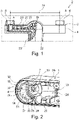
- the 1 shows a sanitary fitting 2 in a plan view, the sanitary fitting 2 in FIG 1 is shown only partially and in a partial section.
- the sanitary fitting 2 has a fitting housing 1 with a (in the 1 not visible) cold water inlet 3 for cold water and a hot water inlet 4 for hot water.
- the hot water inlet 4 is designed in the manner of a receptacle for a first connection nipple 5 and the cold water inlet 3 in the manner of a receptacle for a second connection nipple 6 .
- the first connection nipple 5 is inserted into the hot water inlet 4 and the second connection nipple 6 is inserted into the cold water inlet 3 .
- the first connection nipple 5 and the second connection nipple 6 each have an inlet 8 which is spaced apart from one another by a distance 24 .
- a hot water supply line can be connected to the first connection nipple 5 and a cold water supply line, not shown here, can be connected to the second connection nipple 6 .
- the first connection nipple 5 and the second connection nipple 6 are each connected to a water supply 20 arranged in the fitting housing 1, via which the hot water and the cold water can be fed separately from one another and without contact to the fitting housing 1 to a mixing valve 19 of the sanitary fitting 2.
- the hot water and cold water can be mixed to form a mixed water with a desired mixed water temperature by means of the mixing valve 19 .
- the mixing valve 19 can be actuated with the aid of an actuating element 22 so that the mixed water temperature and a discharge quantity of the mixed water through the sanitary fitting 2 can be adjusted with the actuating element 22 are.
- the actuating element 22 is designed here in the manner of an actuating lever.
- the mixed water can be routed from the mixing valve 19 via a mixed water duct (not visible here) within the fitting housing 1 and without contact to the fitting housing 1 to an outlet opening (not visible here) of an outlet 23 of the fitting housing 1 .
- the 2 shows the valve body 1 in the 1 Sanitary fitting 2 shown in the area of the hot water inlet 4.
- the fitting housing 1 has on a rear side 26 a mounting opening 25 through a in the 1 cover 27 shown can be closed.
- the cover 27 is in the 2 not shown, so that an installation space 28 formed in the fitting housing 1 is visible.
- the hot water inlet 4 is designed in the manner of a bore or cylindrical and extends from the back 26 or the installation opening 25 of the fitting housing 1 along a longitudinal axis 14 into the fitting housing 1 or the installation space 28 of the fitting housing 1.
- the hot water inlet 4 points parallel to the longitudinal axis 14 has a receiving length 29 and orthogonal to the longitudinal axis 14 has a receiving diameter 30 .
- a first internal thread 32 is also formed on an inner peripheral surface 31 of the hot water inlet 4 .
- In the hot water inlet 4 are a ring segment-shaped recess 13, a first locking contour 33 and in the 2 formed non-visible second blocking contour.
- the first blocking contour 33 and the second blocking contour lie opposite one another in a circumferential direction 34 of the hot water inlet 4 .
- the first blocking contour 33 and the second blocking contour are offset from one another at an angle 35 about the longitudinal axis 14 .
- the first blocking contour 33 and the second blocking contour have a blocking contour length 36 parallel to the longitudinal axis 34 and a blocking contour width 38 in a radial direction 37 or orthogonal to the longitudinal axis 14 .
- the first locking contour 33 is a rotation of the 1 shown first connection nipple 5 counterclockwise about the longitudinal axis 14 and by the second blocking contour a rotation of the first connection nipple 5 clockwise about the longitudinal axis 14 can be prevented.
- the recess 13, the first locking contour 33 and the second locking contour are therefore part of an anti-twist device 7 for the first connection nipple 5.
- the in the 1 shown cold water inlet 3 of the fitting housing 1 is mirror symmetrical to that in the 1 shown hot water inlet 4 formed and has a corresponding anti-twist device 7 for the second connection nipple 6.
- the remarks on that in the 2 shown hot water inlet 4 and the anti-rotation device 7 are thus corresponding to the in the 1 shown cold water inlet 3 of the fitting housing 1 transferrable.
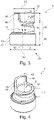
- the 3 shows a first embodiment of in the 1 shown first connection nipple 5 in a perspective view, wherein the in the 1 shown second connection nipple 6 can be identical to the first connection nipple 5 shown here.
- the first connection nipple 5 has a first tubular section 40 and a second tubular section 41 .
- the inlet 8 is formed on a first longitudinal end 39 of the first tubular section 40 and an outlet 9 of the first connection nipple 5 on a second longitudinal end 16 of the second tubular section 41, so that the first connection nipple 5 runs from the inlet 8 to the outlet 9 from which hot water (or cold water) can flow.
- An inflow longitudinal axis 10 of the inflow 8 or the first tubular section 40 runs parallel and at a distance 11 to an outflow longitudinal axis 12 of the outflow 9 or the second tubular section 41.
- the inflow 8 and the outflow 9 are therefore formed eccentrically to one another. That in the 1
- the distance 24 shown can be adjusted by inserting a first connection nipple 5 and a second connection nipple 6 with a suitable eccentricity of their inlet 8 and outlet 9 into the cold water inlet 3 and hot water inlet 4 .
- the first tubular section 40 has a first outside diameter 42 and the second tubular section 41 has a second outside diameter 43 .
- the second outer diameter 43 corresponds in particular (essentially) to that in FIG 2
- a first outer peripheral surface 44 of the first tubular section 40 is formed with a first external thread 45 which may have a diameter of 3/4 inch.
- the hot water supply line for the hot water can be fastened to the first external thread 45 .
- a second outer peripheral surface 46 of the second tubular portion 41 is unthreaded.
- a positive-locking structure 15 is formed on the second longitudinal end 16 or on an end face 47 of the second tubular section 41 .
- the form-fitting structure 15 is designed in the manner of a cam and extends from the second longitudinal end 16 or the end face 47 parallel to the longitudinal axis 12 of the outlet.
- a fastening groove 21 is formed coaxially to the longitudinal inflow axis 10 on the second outer peripheral surface 46 , so that the fastening groove 21 does not extend completely around the second outer peripheral surface 46 or the longitudinal outflow axis 12 .
- the fastening groove 21 is interrupted or not formed, in particular, at least in the area of the positive-locking structure 15 .
- the 4 shows the first variant of the first connection nipple 5 in a perspective view.
- the outlet 9, the end face 47, the second tubular section 41 and the form-fitting structure 15 extend coaxially to the longitudinal axis 12 of the outlet 2 shown first blocking contour 33 corresponding third blocking contour 48 and a fourth blocking contour 49 corresponding to the second blocking contour.
- the figure 5 shows the valve body 1 in the area of the hot water inlet 4, after the in the Figures 3 and 4 shown first embodiment variant of the first connecting nipple 5 with its second tubular section 41 was inserted parallel to the longitudinal axis 14 of the hot water inlet 4 in the first hot water inlet 4 of the fitting housing 1.
- the in the Figures 3 and 4 The form-fitting structure 15 shown of the first connection nipple 5 engages with the arrangement of the first connection nipple 5 in the hot water inlet 4 in the in the 2 Recess 13 shown in the anti-rotation device 7, so that the third locking contour 48 on the also in the 2 shown first locking contour 33 and the fourth locking contour 49 abut the second locking contour.
- the first connection nipple 5 in the hot water inlet 4 can neither be rotated clockwise nor counterclockwise about the longitudinal axis 14 .
- the fitting housing 1 has an axial lock 17 .
- the axial lock 17 includes a locking element 18, which is in a (in the figure 5 covered) threaded bore 50 of the fitting housing 1 is screwed, so that the closing element 18 (tangentially) engages in the fastening groove 21 of the first connecting nipple 5 .
- the first connection nipple 5 is secured in an axial direction 51 (parallel to the longitudinal axis 14), so that the first connection nipple 5 cannot become detached from the hot water inlet 4.
- the 6 shows the closing element 18 in a perspective view.
- the closing element 18 is designed in the manner of a threaded pin.
- the 7 shows a second embodiment of a first connection nipple 5 in a perspective view, wherein the in the 1 shown second connection nipple 6 can be identical to the first connection nipple 5 shown here.
- the inlet 8 and the outlet 9 are coaxial with one another.
- the second embodiment of the first connection nipple 5 is therefore straight.
- the second embodiment of the first connection nipple 5 (and second connection nipple 6) can be used when in the 1 distance 24 shown should correspond to a distance between the cold water inlet 3 and hot water inlet 4, for example 150 mm.
- the second embodiment of the first connection nipple 5 also has a second external thread 52, with which the first connection nipple 5 in the 2 shown first internal thread 32 of the hot water inlet 4 can be screwed.
- the 8 shows a union nut 53 in a perspective view.
- the union nut 53 is in the 7 shown second embodiment of the first connection nipple 5 (or a correspondingly designed second connection nipple 6) attachable before the first connection nipple 5 to the in the 1 shown fitting housing 1 was attached.
- the union nut 53 can be fastened to a peripheral collar 54 of the first connection nipple 5 .
- the union nut 53 has a second internal thread 55 which can have a diameter of 3/4 inch.
- the fitting housing can be easily adapted to different line distances between a cold water supply line and a hot water supply line.
Landscapes
- Health & Medical Sciences (AREA)
- Life Sciences & Earth Sciences (AREA)
- Engineering & Computer Science (AREA)
- Hydrology & Water Resources (AREA)
- Public Health (AREA)
- Water Supply & Treatment (AREA)
- Multiple-Way Valves (AREA)
- Domestic Plumbing Installations (AREA)
Abstract
Description
- Die vorliegende Erfindung betrifft ein Armaturengehäuse für eine Sanitärarmatur und eine Sanitärarmatur mit einem Armaturengehäuse. Mit der Sanitärarmatur ist insbesondere Mischwasser mit einer gewünschten Mischwassertemperatur beispielsweise an Waschbecken, Spülbecken, Duschen und/oder Badewannen bereitstellbar.
- Sanitärarmaturen können beispielsweise nach Art von sogenannten Aufputzsanitärarmaturen ausgebildet sein, die an eine Gebäudewand montierbar sind und dabei an eine Kaltwasserzuführleitung für Kaltwasser und Warmwasserzuführleitung für Warmwasser angeschlossen werden müssen. Hierzu muss ein Abstand zwischen einem Kaltwasserzulauf und Warmwasserzulauf der Sanitärarmatur einem Leitungsabstand zwischen der Kaltwasserzuführleitung und Warmwasserzuführleitung entsprechen, mit dem die Kaltwasserzuführleitung und Warmwasserzuführleitung aus der Gebäudewand ragen. Der Leitungsabstand kann in unterschiedlichen Ländern aufgrund unterschiedlicher Normungen variieren. So kann der Leitungsabstand beispielsweise in Deutschland 150 mm (Millimeter), in der Schweiz 153 mm oder in Schweden 160 mm betragen. Bei einem Armaturengehäuse aus Messingguss können der Kaltwasserzulauf und der Warmwasserzulauf im erforderlichen Abstand in das Armaturengehäuse gebohrt oder durch mehrteilige S-Anschlüsse realisiert werden. Dies ist bei Armaturengehäusen, die ein nicht wasserführendes Außengehäuse mit innenliegenden Wasserführungen aus Kunststoff aufweisen, jedoch nicht ohne weiteres möglich. Bei solchen Armaturengehäusen müssen geeignete Abstände zwischen dem Kaltwasserzulauf und Warmwasserzulauf durch unterschiedliche Außengehäuse, Rückwände und/oder unterschiedlich lang ausgeführte Wasserführungen aus Kunststoff realisiert werden. Dies ist mit einem hohen Fertigungsaufwand verbunden.
- Aufgabe der Erfindung ist es daher, die mit Bezug auf den Stand der Technik geschilderten Probleme zumindest teilweise zu lösen und insbesondere ein Armaturengehäuse anzugeben, das leicht an unterschiedliche Leitungsabstände zwischen einer Kaltwasserzuführleitung und Warmwasserzuführleitung anpassbar ist. Zudem soll auch eine Sanitärarmatur angegeben werden, deren Armaturengehäuse leicht an unterschiedliche Leitungsabstände zwischen einer Kaltwasserzuführleitung und Warmwasserzuführleitung anpassbar ist.
- Diese Aufgaben werden gelöst mit einem Armaturengehäuse und einer Sanitärarmatur gemäß den Merkmalen der unabhängigen Patentansprüche. Weitere vorteilhafte Ausgestaltungen der Erfindung sind in den abhängigen Patentansprüchen angegeben. Es ist darauf hinzuweisen, dass die in den abhängigen Patentansprüchen einzeln aufgeführten Merkmale in beliebiger technologisch sinnvoller Weise miteinander kombiniert werden können und weitere Ausgestaltungen der Erfindung definieren. Darüber hinaus werden die in den Patentansprüchen angegebenen Merkmale in der Beschreibung näher präzisiert und erläutert, wobei weitere bevorzugte Ausgestaltungen der Erfindung dargestellt werden.
- Hierzu trägt ein Armaturengehäuse für eine Sanitärarmatur bei, das zumindest Folgendes aufweist:
- einen Kaltwasserzulauf und einen Warmwasserzulauf;
- zumindest einen Anschlussnippel, der in den Kaltwasserzulauf oder den Warmwasserzulauf eingesteckt ist; und
- zumindest eine Verdrehsicherung, durch die ein Drehen des zumindest einen Anschlussnippels in dem Kaltwasserzulauf oder Warmwasserzulauf verhinderbar ist.
- Die Sanitärarmatur dient insbesondere der bedarfsgerechten Bereitstellung von Mischwasser an einem Waschbecken, einem Spülbecken, einer Dusche und/oder einer Badewanne. Hierzu kann die Sanitärarmatur ein Mischventil, beispielsweise nach Art einer Mischkartusche oder Thermostatmischkartusche, aufweisen, durch das Kaltwasser mit einer Kaltwassertemperatur und Warmwasser mit einer Warmwassertemperatur zu Mischwasser mit einer gewünschten Mischwassertemperatur mischbar sind. Die Warmwassertemperatur beträgt insbesondere maximal 90 °C, bevorzugt 25 °C bis 90 °C, besonders bevorzugt 55 °C bis 65 °C und/oder die Kaltwassertemperatur insbesondere maximal 25 °C (Celsius), bevorzugt 1 °C bis 25 °C, besonders bevorzugt 5 °C bis 20 °C. Das Mischventil ist insbesondere in einem Armaturengehäuse der Sanitärarmatur angeordnet, mit dem die Sanitärarmatur an einem Träger, wie zum Beispiel einer Wand, befestigbar ist.
- Das Mischventil kann, beispielsweise zur Einstellung der Mischwassertemperatur und/oder einer Abgabemenge des Mischwassers, mithilfe zumindest eines Betätigungselements betätigbar sein. Das zumindest eine Betätigungselement kann beispielsweise nach Art eines, insbesondere drehbaren und/oder schwenkbaren, Betätigungshebels oder Drehelements ausgebildet sein. Weiterhin kann das zumindest eine Betätigungselement an dem Armaturengehäuse befestigt sein.
- Das Armaturengehäuse kann einen, beispielsweise starren oder schwenkbaren, Auslauf mit einer Auslauföffnung aufweisen, über die das Mischwasser abgebbar ist. Weiterhin kann das Armaturengehäuse als Außengehäuse ausgebildet sein und/oder einen innenliegenden Montageraum aufweisen. Der Montageraum kann eine Montageöffnung aufweisen, über die beispielsweise zumindest eine innenliegende Wasserführung und/oder das Mischventil in dem Montageraum montierbar sind. Die zumindest eine innenliegende Wasserführung kann beispielsweise rohrförmig ausgebildet sein und/oder zumindest teilweise aus Kunststoff bestehen. Die Montageöffnung kann insbesondere an einer Rückseite des Armaturengehäuses ausgebildet und/oder mit einem (lösbaren) Deckel verschlossen sein. Das Armaturengehäuse bzw. das Außengehäuse können zumindest teilweise aus Kunststoff oder Metall, wie zum Beispiel Messing, Messinglegierung oder Zinklegierung, bestehen. Beispielsweise kann das Armaturengehäuse bzw. das Außengehäuse nach Art eines Zinkdruckgussgehäuses ausgebildet sein. Das Kaltwasser, Warmwasser und/oder Mischwasser sind innerhalb des Armaturengehäuses insbesondere ohne Kontakt zu dem Armaturengehäuse führbar.
- Das Armaturengehäuse weist einen Kaltwasserzulauf für das Kaltwasser und einen Warmwasserzulauf für das Warmwasser auf. Der Kaltwasserzulauf und/oder Warmwasserzulauf können jeweils nach Art einer Öffnung, Bohrung und/oder Aufnahme in dem Armaturengehäuse ausgebildet sein. Weiterhin können der Kaltwasserzulauf und/oder der Warmwasserzulauf an der Rückseite des Armaturengehäuses ausgebildet sein und/oder sich von der Rückseite in das Armaturengehäuse erstrecken. Zudem können der Kaltwasserzulauf und/oder der Warmwasserzulauf sich entlang einer (geraden) Längsachse erstrecken und/oder zumindest teilweise (orthogonal zu der Längsachse) einen runden Querschnitt aufweisen. Beispielsweise können der Kaltwasserzulauf und/oder der Warmwasserzulauf einen Aufnahmedurchmesser von 10 mm bis 50 mm [Millimeter] und/oder eine Aufnahmelänge von 5 mm bis 50 mm aufweisen. Der Kaltwasserzulauf und der Warmwasserzulauf können identisch und/oder spiegelsymmetrisch zueinander ausgebildet sein. Bei der Längsachse kann es sich insbesondere um eine Zentrumsachse des Kaltwasserzulaufs und/oder Warmwasserzulaufs handeln. Der Kaltwasserzulauf und Warmwasserzulauf können parallel zueinander angeordnet sein und/oder einen (ersten) Abstand zueinander aufweisen, der beispielsweise (im Wesentlichen) 150 mm [Millimeter] betragen kann. Der Abstand bemisst sich insbesondere zwischen den Längsachsen des Kaltwasserzulaufs und Warmwasserzulaufs. Von dem Kaltwasserzulauf und/oder Warmwasserzulauf kann die zumindest eine Wasserführung zu dem Mischventil führen.
- Das Armaturengehäuse weist zumindest einen Anschlussnippel auf, der in den Kaltwasserzulauf und/oder den Warmwasserzulauf eingesteckt ist. Unter einem "Anschlussnippel" kann insbesondere ein (kurzes) Rohrverbindungsstück verstanden werden. Insbesondere können in den Warmwasserzulauf und den Kaltwasserzulauf jeweils ein Anschlussnippel eingesteckt sein. Der Anschlussnippel des Warmwasserzulaufs und der Anschlussnippel des Kaltwasserzulaufs können identisch ausgebildet sein. Unter "eingesteckt" kann insbesondere verstanden werden, dass der zumindest eine Anschlussnippel in den Kaltwasserzulauf und/oder den Warmwasserzulauf durch eine (lineare) Bewegung entlang der Längsachse des Kaltwasserzulaufs und/oder des Warmwasserzulaufs in den Kaltwasserzulauf und/oder den Warmwasserzulauf hineinbewegbar und herausbewegbar ist. Weiterhin kann unter "eingesteckt" insbesondere verstanden werden, dass der zumindest eine Anschlussnippel nicht in den Kaltwasserzulauf und/oder den Warmwasserzulauf geschraubt ist. Somit kann der zumindest eine Anschlussnippel ohne Drehen um die Längsachse in dem Kaltwasserzulauf und/oder Warmwasserzulauf angeordnet werden. Der zumindest eine Anschlussnippel kann zumindest teilweise rohrförmig ausgebildet sein und/oder zumindest teilweise aus Kunststoff oder Metall, wie zum Beispiel Messing, bestehen.
- Der zumindest eine Anschlussnippel kann sich von einem Zulauf des zumindest einen Anschlussnippels zu einem Ablauf des zumindest einen Anschlussnippels erstrecken. Der Zulauf und der Ablauf können an längsseitigen Enden des zumindest einen Anschlussnippels ausgebildet sein. Weiterhin kann der Zulauf nach Art einer Zulaufseite des Anschlussnippels ausgebildet und/oder eine Zulauföffnung aufweisen. Zudem kann der Ablauf nach Art einer Ablaufseite des Anschlussnippels ausgebildet und/oder eine Ablauföffnung aufweisen. Der zumindest eine Anschlussnippel ist insbesondere mit dem Ablauf bzw. mit seiner Ablauföffnung in den Kaltwasserzulauf und/oder den Warmwasserzulauf einsteckbar, sodass der Ablauf bzw. die Ablauföffnung insbesondere flüssigkeitsleitend mit der zumindest einen Wasserführung verbunden ist. Der Zulauf bzw. die Zulauföffnung des zumindest einen Anschlussnippels können insbesondere aus dem Armaturengehäuse herausragen. Die Kaltwasserzuführleitung und/oder die Warmwasserzuführleitung sind an den Zulauf bzw. die Zulauföffnung des zumindest einen Anschlussnippels anschließbar, sodass das Kaltwasser und/oder das Warmwasser durch den zumindest einen Anschlussnippel in das Armaturengehäuse strömen kann.
- Der zumindest eine Anschlussnippel kann ein (erstes) Gewinde, insbesondere Außengewinde, aufweisen. Bei dem Gewinde kann es sich insbesondere um ein ¾-Zoll-Gewinde handeln. Weiterhin kann der zumindest eine Anschlussnippel zumindest teilweise S-förmig ausgebildet sein. Durch ein Drehen des zumindest einen Anschlussnippels in dem Kaltwasserzulauf und/oder Warmwasserzulauf ist dadurch eine Position des Zulaufs bzw. der Zulauföffnung des zumindest einen Anschlussnippels relativ zu dem Armaturengehäuse einstellbar. Zudem ist hierdurch ein Abstandsmaß zwischen einem ersten Zulauf eines ersten Anschlussnippels des Warmwasserzulaufs und einem zweiten Zulauf eines zweiten Anschlussnippels des Kaltwasserzulaufs änderbar, sodass das Abstandsmaß insbesondere an einen Leitungsabstand zwischen der Warmwasserzuführleitung und Kaltwasserzuführleitung anpassbar ist. Das Abstandsmaß bemisst sich insbesondere zwischen einer ersten Zulauflängsachse des ersten Zulaufs und einer zweiten Zulauflängsachse des zweiten Zulaufs. Das Abstandsmaß kann beispielsweise auf 130 mm bis 170 mm [Millimeter], bevorzugt 140 bis 160 mm einstellbar sein. Optional kann der Kaltwasserzulauf und/oder der Warmwasserzulauf ein (zweites) Gewinde, insbesondere Innengewinde, aufweisen, über das ein gerader (schraubbarer) Anschlussnippel in dem Kaltwasserzulauf und/oder Warmwasserzulauf befestigbar ist. Ein gerader bzw. glatter Anschlussnippel kann in dem Kaltwasserzulauf und Warmwasserzulauf insbesondere angeordnet werden, wenn der Abstand zwischen dem Kaltwasserzulauf und dem Warmwasserzulauf dem Leitungsabstand zwischen der Kaltwasserzuführleitung und der Warmwasserzuführleitung entspricht.
- Das Armaturengehäuse weist zumindest eine Verdrehsicherung auf, durch die ein Drehen des zumindest einen Anschlussnippels in dem Kaltwasserzulauf oder Warmwasserzulauf verhinderbar ist. Insbesondere kann das Armaturengehäuse für jeden Anschlussnippel eine Verdrehsicherung aufweisen. Beispielsweise kann das Armaturengehäuse eine erste Verdrehsicherung für den ersten Anschlussnippel des Warmwasserzulaufs und eine zweite Verdrehsicherung für den zweiten Anschlussnippel des Kaltwasserzulaufs aufweisen. Zudem kann die zumindest eine Verdrehsicherung beispielsweise aktivierbar und deaktivierbar sein, wobei in einem aktivierten Zustand der zumindest einen Verdrehsicherung der zumindest eine Anschlussnippel in dem Kaltwasserzulauf und/oder Warmwasserzulauf nicht drehbar und in einem deaktivierten Zustand der zumindest einen Verdrehsicherung der zumindest eine Anschlussnippel in dem Kaltwasserzulauf und/oder Warmwasserzulauf drehbar ist. Zum Aktivieren und/oder Deaktivieren der zumindest einen Verdrehsicherung kann das Armaturengehäuse insbesondere zumindest ein Stellelement, beispielsweise nach Art eines Hebels oder Drehelements, aufweisen. Weiterhin kann die zumindest eine Verdrehsicherung zumindest ein Klemmelement aufweisen, mittels dem der zumindest eine Anschlussnippel in dem Kaltwasserzulauf und/oder Warmwasserzulauf festklemmbar ist. Das zumindest eine Klemmelement kann beispielsweise auf eine Umfangsfläche des zumindest einen Anschlussnippels pressbar sein.
- Der zumindest eine Anschlussnippel kann einen Zulauf und einen Ablauf aufweisen, die exzentrisch zueinander ausgebildet sind. Dies kann insbesondere bedeuten, dass der Zulauf und der Ablauf nicht konzentrisch zueinander und/oder die Zulauföffnung und die Ablauföffnung nicht konzentrisch zueinander ausgebildet sind. Über den Zulauf bzw. die Zulauföffnung kann das Kaltwasser und/oder Warmwasser insbesondere in den zumindest einen Anschlussnippel einströmen und/oder über den Ablauf bzw. die Ablauföffnung insbesondere aus dem zumindest einen Anschlussnippel ausströmen.
- Eine Zulauflängsachse eines Zulaufs des zumindest einen Anschlussnippels kann mit einem (zweiten) Abstand zu einer Ablauflängsachse eines Ablaufs des zumindest einen Anschlussnippels verlaufen. Weiterhin kann die Zulauflängsachse insbesondere parallel zu der Ablauflängsachse verlaufen. Bei der Zulauflängsachse kann es sich insbesondere um eine Zentrumsachse des Zulaufs bzw. der Zulauföffnung und/oder bei der Ablauflängsachse um eine Zentrumsachse des Ablaufs bzw. der Ablauföffnung handeln. Der (zweite) Abstand zwischen der Zulauflängsachse und der Ablauflängsachse kann beispielsweise 1 mm bis 10 mm [Millimeter], bevorzugt 1,5 mm oder 5 mm, betragen. Beträgt der (zweite) Abstand 1,5 mm, ist das Abstandsmaß zwischen dem ersten Zulauf des ersten Anschlussnippels des Warmwasserzulaufs und dem zweiten Zulauf des zweiten Anschlussnippels des Kaltwasserzulaufs auf 153 mm einstellbar, wenn der (erste) Abstand zwischen dem Warmwasserzulauf und Kaltwasserzulauf 150 mm beträgt. Beträgt der (zweite) Abstand 5 mm, ist das Abstandsmaß zwischen dem ersten Zulauf des ersten Anschlussnippels des Warmwasserzulaufs und dem zweiten Zulauf des zweiten Anschlussnippels des Kaltwasserzulaufs auf 160 mm einstellbar, wenn der (erste) Abstand zwischen dem Warmwasserzulauf und Kaltwasserzulauf 150 mm beträgt. Je nach gewünschtem bzw. erforderlichem Abstandsmaß zwischen dem ersten Zulauf und zweiten Zulauf, können Anschlussnippel mit entsprechend angepasstem (zweiten) Abstand zwischen der Zulauflängsachse und der Ablauflängsachse in den Warmwasserzulauf und Kaltwasserzulauf eingesteckt bzw. angeordnet werden.
- Die zumindest eine Verdrehsicherung kann als formschlüssige Verbindung zwischen dem zumindest einen Anschlussnippel und dem Kaltwasserzulauf und/oder zwischen dem zumindest einen Anschlussnippel und dem Warmwasserzulauf ausgebildet sein. Die formschlüssige Verbindung kann insbesondere durch ein Ineinandergreifen von Verbindungspartnern des zumindest einen Anschlussnippels und des Kaltwasserzulaufs und/oder durch ein Ineinandergreifen von Verbindungspartnern des zumindest einen Anschlussnippels und des Warmwasserzulaufs gebildet sein. Durch die formschlüssige Verbindung ist der zumindest eine Anschlussnippel insbesondere weder im Uhrzeigersinn noch gegen den Uhrzeigersinn in dem Kaltwasserzulauf und/oder Warmwasserzulauf drehbar. Die formschlüssige Verbindung kann beispielsweise nach Art einer Welle-Nabe-Verbindung, Verzahnung und/oder Steckverzahnung ausgebildet sein. Weiterhin kann die formschlüssige Verbindung beispielsweise mithilfe einer Passfeder erfolgen. Beispielsweise kann die formschlüssige Verbindung derart ausgebildet sein, dass der zumindest eine Anschlussnippel (nur) in einer einzigen Orientierung in den Kaltwasserzulauf und/oder den Warmwasserzulauf einsteckbar ist.
- Die zumindest eine Verdrehsicherung kann zumindest eine in dem Armaturengehäuse ausgebildete Aussparung umfassen. Die Aussparung ist insbesondere in dem Kaltwasserzulauf und/oder Warmwasserzulauf ausgebildet und/oder erstreckt sich von dem Kaltwasserzulauf und/oder Warmwasserzulauf in das Armaturengehäuse. Beispielsweise kann die zumindest eine Aussparung nach Art einer Nut oder Tasche ausgebildet sein. Die Nut oder Tasche können insbesondere in das Armaturengehäuse gefräst sein. Durch die zumindest eine Aussparung kann in dem Kaltwasserzulauf und/oder Warmwasserzulauf zumindest eine Sperrkontur ausgebildet sein. Beispielsweise kann durch die zumindest eine Aussparung in dem Kaltwasserzulauf und/oder Warmwasserzulauf eine erste Sperrkontur und zweite Sperrkontur ausgebildet sein, die sich insbesondere in einer Umfangsrichtung des Kaltwasserzulaufs und/oder Warmwasserzulaufs gegenüberliegen. Die erste Sperrkontur und die zweite Sperrkontur können in der Umfangsrichtung beispielsweise mit einem (ersten) Winkel von 10° bis 180°, bevorzugt 70° bis 110°, versetzt zueinander ausgebildet sein. Zudem kann die zumindest eine Sperrkontur nach Art einer, insbesondere rechteckigen und/oder flachen, Fläche ausgebildet sein. Die zumindest eine Sperrkontur bzw. die Fläche können sich zudem parallel zu der Längsachse und/oder in eine radiale Richtung (orthogonal zu der Längsachse) erstrecken. Weiterhin kann die zumindest eine Sperrkontur beispielsweise (parallel zu der Längsachse) eine Sperrkonturlänge von 2 mm bis 30 mm, bevorzugt 5 mm bis 20 mm, und/oder (orthogonal zu der Längsachse und/oder in die radiale Richtung) eine Sperrkonturbreite von 1 mm bis 10 mm [Millimeter], bevorzugt 1 mm bis 5 mm, aufweisen.
- Nach dem Einstecken des zumindest einen Anschlussnippels in den Kaltwasserzulauf und/oder den Warmwasserzulauf kann der zumindest eine Anschlussnippel in die zumindest eine Aussparung eingreifen, sodass der zumindest eine Anschlussnippel in dem Kaltwasserzulauf und/oder Warmwasserzulauf nicht drehbar ist.
- Die zumindest eine Aussparung kann sich zumindest teilweise parallel zu einer Längsachse des Kaltwasserzulaufs und/oder Warmwasserzulaufs erstrecken.
- Die zumindest eine Verdrehsicherung kann eine an dem zumindest einen Anschlussnippel ausgebildete Formschlussstruktur umfassen. Die Formschlusskontur kann beispielsweise nach Art eines Nockens, Zahns, Nase und/oder Zapfens ausgebildet sein. Der zumindest eine Anschlussnippel kann einstückig mit der Formschlusskontur ausgebildet sein. An der Formschlusskontur kann beispielsweise eine dritte Sperrkontur und vierte Sperrkontur ausgebildet sein. Die dritte Sperrkontur und vierte Sperrkontur können sich insbesondere in der Umfangsrichtung gegenüberliegen. Zudem können die dritte Sperrkontur und die vierte Sperrkontur in der Umfangsrichtung beispielsweise mit einem (zweiten) Winkel versetzt zueinander ausgebildet sein, der (im Wesentlichen) dem (ersten) Winkel entspricht, mit dem die erste Sperrkontur und zweite Sperrkontur in der Umfangsrichtung versetzt zueinander ausgebildet sind. Der (zweiten) Winkel kann beispielsweise 10° bis 180°, bevorzugt 70° bis 110°, betragen. Darüber hinaus kann die Formschlussstruktur (orthogonal zu der Längsachse bzw. orthogonal zu der Ablauflängsachse) einen ringsegmentförmigen Querschnitt aufweisen. Die Formschlussstruktur greift insbesondere in die Aussparung ein, wenn der zumindest eine Anschlussnippel in dem Kaltwasserzulauf und/oder Warmwasserzulauf eingesteckt ist. Hierdurch kann die dritte Sperrkontur an der erste Sperrkontur und die vierte Sperrkontur an der ersten Sperrkontur anliegen, sodass der zumindest eine Anschlussnippel in dem Kaltwasserzulauf und/oder Warmwasserzulauf nicht drehbar ist.
- Die Formschlussstruktur kann an einem längsseitigen Ende des zumindest einen Anschlussnippels ausgebildet sein. Insbesondere ist die Formschlussstruktur an dem längsseitigen Ende des zumindest einen Anschlussnippels ausgebildet, an dem sich der Ablauf bzw. die Ablauföffnung befindet.
- Das Armaturengehäuse kann zumindest eine Axialsicherung für den zumindest einen Anschlussnippel aufweisen. Durch die Axialsicherung ist der zumindest eine Anschlussnippel insbesondere in dem Kaltwasserzulauf und/oder Warmwasserzulauf sicherbar, sodass der zumindest eine Anschlussnippel nicht aus dem Kaltwasserzulauf und/oder Warmwasserzulauf herausziehbar ist. Insbesondere weist das Armaturengehäuse eine erste Axialsicherung für den ersten Anschlussnippel und eine zweite Axialsicherung für den zweiten Anschlussnippel auf.
- Die zumindest eine Axialsicherung kann ein Schließelement umfassen, mit dem ein Lösen des zumindest einen Anschlussnippels aus dem Kaltwasserzulauf und/oder Warmwasserzulauf verhinderbar ist. Das Schließelement kann beispielsweise nach Art eines Gewindestifts, Steckschraube, Kerbstifts oder Niets ausgebildet sein. Weiterhin kann das Schließelement beispielsweise in das Armaturengehäuse eingesteckt oder in eine Gewindebohrung des Armaturengehäuses eingeschraubt sein. Zudem kann das Schließelement beispielsweise in eine Befestigungsnut des zumindest einen Anschlussnippels, insbesondere orthogonal zu der Längsachse oder tangential, eingreifen. Die Befestigungsnut kann sich beispielsweise zumindest teilweise in der Umfangsrichtung entlang einer äußeren Umfangsfläche des zumindest einen Anschlussnippels erstrecken. Vorzugsweise erstreckt sich die Befestigungsnut in der Umfangsrichtung nicht vollständig über die äußere Umfangsfläche des zumindest einen Anschlussnippels. Hierzu kann die Befestigungsnut beispielsweise nach Art eines exzentrischen Rotationsausschnitts ausgebildet sein. Hierdurch ist eine Kerbwirkung reduzierbar.
- Einem weiteren Aspekt folgend wird auch eine Sanitärarmatur vorgeschlagen, die zumindest Folgendes aufweist:
- ein hier vorgeschlagenes Armaturengehäuse; und
- ein Mischventil zum Mischen von Kaltwasser und Warmwasser.
- Für weitere Einzelheiten zu der Sanitärarmatur wird vollumfänglich auf die Beschreibung des Armaturengehäuses verwiesen.
- Die Erfindung sowie das technische Umfeld werden nachfolgend anhand der Figuren näher erläutert. Es ist darauf hinzuweisen, dass die Figuren besonders bevorzugte Ausführungsvarianten der Erfindung zeigen, diese jedoch nicht darauf beschränkt ist. Dabei sind gleiche Bauteile in den Figuren mit denselben Bezugszeichen versehen. Es zeigen beispielhaft und schematisch:
- Fig. 1:
- eine Sanitärarmatur mit einem Armaturengehäuse in einer Draufsicht;
- Fig. 2:
- das Armaturengehäuse im Bereich eines Warmwasserzulaufs in einer perspektivischen Darstellung;
- Fig. 3:
- ein erste Ausführungsvariante eines ersten Anschlussnippels des Armaturengehäuses in einer Seitenansicht;
- Fig. 4:
- die erste Ausführungsvariante des ersten Anschlussnippels des Armaturengehäuses in einer perspektivischen Darstellung;
- Fig. 5:
- das Armaturengehäuse im Bereich des Warmwasserzulaufs mit der ersten Ausführungsvariante des Anschlussnippels in einer perspektivischen Darstellung;
- Fig. 6:
- ein Schließelement des Armaturengehäuses in einer perspektivischen Darstellung;
- Fig. 7:
- eine zweite Ausführungsvariante eines ersten oder zweiten Anschlussnippels des Armaturengehäuses in einer perspektivischen Darstellung; und
- Fig. 8:
- eine Überwurfmutter für die zweite Ausführungsvariante des ersten oder zweiten Anschlussnippels.
- Die
Fig. 1 zeigt eine Sanitärarmatur 2 in einer Draufsicht, wobei die Sanitärarmatur 2 in derFig. 1 nur teilweise sowie in einem Teilschnitt dargestellt ist. Die Sanitärarmatur 2 weist ein Armaturengehäuse 1 mit einem (in derFig. 1 nicht sichtbaren) Kaltwasserzulauf 3 für Kaltwasser und einem Warmwasserzulauf 4 für Warmwasser auf. Der Warmwasserzulauf 4 ist nach Art einer Aufnahme für einen ersten Anschlussnippel 5 und der Kaltwasserzulauf 3 nach Art einer Aufnahme für einen zweiten Anschlussnippel 6 ausgebildet. In den Warmwasserzulauf 4 ist der erster Anschlussnippel 5 und in den Kaltwasserzulauf 3 der zweiter Anschlussnippel 6 eingesteckt. Der erste Anschlussnippel 5 und der zweite Anschlussnippel 6 weisen jeweils einen Zulauf 8 auf, die mit einem Abstandsmaß 24 voneinander beabstandet sind. An den ersten Anschlussnippel 5 ist eine hier nicht gezeigte Warmwasserzuführleitung und an den zweiten Anschlussnippel 6 eine hier nicht gezeigte Kaltwasserzuführleitung anschließbar. Der erste Anschlussnippel 5 und der zweite Anschlussnippel 6 sind jeweils mit einer in dem Armaturengehäuse 1 angeordneten Wasserführung 20 verbunden, über die das Warmwasser und das Kaltwasser getrennt voneinander und ohne Kontakt zu dem Armaturengehäuse 1 einem Mischventil 19 der Sanitärarmatur 2 zuführbar sind. Mittels dem Mischventil 19 sind das Warmwasser und Kaltwasser zu einem Mischwasser mit einer gewünschten Mischwassertemperatur mischbar. Das Mischventil 19 ist mithilfe eines Betätigungselements 22 betätigbar, sodass mit dem Betätigungselement 22 die Mischwassertemperatur und eine Abgabemenge des Mischwassers durch die Sanitärarmatur 2 einstellbar sind. Das Betätigungselement 22 ist hier nach Art eines Betätigungshebels ausgebildet. Das Mischwasser ist von dem Mischventil 19 über eine hier nicht sichtbare Mischwasserführung innerhalb des Armaturengehäuses 1 und ohne Kontakt zu dem Armaturengehäuse 1 zu einer hier nicht sichtbaren Auslauföffnung eines Auslaufs 23 des Armaturengehäuses 1 führbar. - Die
Fig. 2 zeigt das Armaturengehäuse 1 der in derFig. 1 gezeigten Sanitärarmatur 2 im Bereich des Warmwasserzulaufs 4. Das Armaturengehäuse 1 weist an einer Rückseite 26 eine Montageöffnung 25 auf, die durch einen in derFig. 1 gezeigten Deckel 27 verschließbar ist. Der Deckel 27 ist in derFig. 2 nicht dargestellt, sodass ein in dem Armaturengehäuse 1 ausgebildeter Montageraum 28 sichtbar ist. Zudem ist das Armaturengehäuse 1 in derFig. 2 ohne den in derFig. 1 gezeigten ersten Anschlussnippel 5 und ohne die Wasserführung 20 dargestellt, sodass der Warmwasserzulauf 4 sichtbar ist. Der Warmwasserzulauf 4 ist nach Art einer Bohrung bzw. zylinderförmig ausgebildet und erstreckt sich von der Rückseite 26 bzw. der Montageöffnung 25 des Armaturengehäuses 1 entlang einer Längsachse 14 in das Armaturengehäuse 1 bzw. den Montageraum 28 des Armaturengehäuses 1. Der Warmwasserzulauf 4 weist parallel zu der Längsachse 14 eine Aufnahmelänge 29 und orthogonal zu der Längsachse 14 einen Aufnahmedurchmesser 30 auf. An einer inneren Umfangsfläche 31 des Warmwasserzulaufs 4 ist zudem ein erstes Innengewinde 32 ausgebildet. In dem Warmwasserzulauf 4 sind durch eine ringsegmentförmige Aussparung 13 eine erste Sperrkontur 33 und eine in derFig. 2 nicht sichtbare zweite Sperrkontur ausgebildet. Die erste Sperrkontur 33 und die zweite Sperrkontur liegen sich in einer Umfangsrichtung 34 des Warmwasserzulaufs 4 gegenüber. Weiterhin sind die erste Sperrkontur 33 und die zweite Sperrkontur mit einem Winkel 35 um die Längsachse 14 versetzt zueinander angeordnet. Die erste Sperrkontur 33 und die zweite Sperrkontur weisen parallel zu der Längsachse 34 eine Sperrkonturlänge 36 und in einer radialen Richtung 37 bzw. orthogonal zu der Längsachse 14 eine Sperrkonturbreite 38 auf. Durch die erste Sperrkontur 33 ist eine Drehung des in derFig. 1 gezeigten ersten Anschlussnippels 5 gegen den Uhrzeigersinn um die Längsachse 14 und durch die zweite Sperrkontur eine Drehung des ersten Anschlussnippels 5 im Uhrzeigersinn um die Längsachse 14 verhinderbar. Die Aussparung 13, die erste Sperrkontur 33 und die zweite Sperrkontur sind daher Teil einer Verdrehsicherung 7 für den ersten Anschlussnippel 5. Der in derFig. 1 gezeigte Kaltwasserzulauf 3 des Armaturengehäuses 1 ist spiegelsymmetrisch zu dem in derFig. 1 gezeigten Warmwasserzulauf 4 ausgebildet und weist eine entsprechende Verdrehsicherung 7 für den zweiten Anschlussnippel 6 auf. Die Ausführungen zu dem in derFig. 2 gezeigten Warmwasserzulauf 4 und der Verdrehsicherung 7 sind somit entsprechend auf den in derFig. 1 gezeigten Kaltwasserzulauf 3 des Armaturengehäuses 1 übertragbar. - Die
Fig. 3 zeigt eine erste Ausführungsvariante des in derFig. 1 gezeigten ersten Anschlussnippels 5 in einer perspektivischen Darstellung, wobei der in derFig. 1 gezeigte zweite Anschlussnippel 6 identisch zu dem hier gezeigten ersten Anschlussnippel 5 ausgebildet sein kann. Der erste Anschlussnippel 5 weist einen ersten rohrförmigen Abschnitt 40 und einen zweiten rohrförmigen Abschnitt 41 auf. Der Zulauf 8 ist an einem ersten längsseitigen Ende 39 des ersten rohrförmigen Abschnitts 40 und ein Ablauf 9 des ersten Anschlussnippels 5 an einem zweiten längsseitigen Ende 16 des zweiten rohrförmigen Abschnitts 41 ausgebildet, sodass der erste Anschlussnippel 5 von dem Zulauf 8 bis zu dem Ablauf 9 von dem Warmwasser (bzw. Kaltwasser) durchströmbar ist. Eine Zulauflängsachse 10 des Zulaufs 8 bzw. des ersten rohrförmigen Abschnitts 40 verläuft parallel und mit einem Abstand 11 zu einer Ablauflängsachse 12 des Ablaufs 9 bzw. des zweiten rohrförmigen Abschnitts 41. Der Zulauf 8 und der Ablauf 9 sind daher exzentrisch zueinander ausgebildet. Das in derFig. 1 gezeigte Abstandsmaß 24 ist anpassbar, indem ein erster Anschlussnippel 5 und zweiter Anschlussnippel 6 mit geeigneter Exzentrizität ihres Zulaufs 8 und Ablaufs 9 in den Kaltwasserzulauf 3 und Warmwasserzulauf 4 gesteckt werden. Weiterhin weist der erste rohrförmige Abschnitt 40 einen ersten Außendurchmesser 42 und der zweite rohrförmige Abschnitt 41 einen zweiten Außendurchmesser 43 auf. Der zweite Außendurchmesser 43 entspricht insbesondere (im Wesentlichen) dem in derFig. 2 gezeigten Aufnahmedurchmesser 30. An einer ersten äußeren Umfangsfläche 44 des ersten rohrförmigen Abschnitts 40 ist ein erstes Außengewinde 45 ausgebildet, das einen Durchmesser von ¾-Zoll aufweisen kann. An dem ersten Außengewinde 45 ist die Warmwasserzuführleitung für das Warmwasser befestigbar. Eine zweite äußere Umfangsfläche 46 des zweiten rohrförmigen Abschnitts 41 weist kein Gewinde auf. - An dem zweiten längsseitigen Ende 16 bzw. an einer Stirnseite 47 des zweiten rohrförmigen Abschnitts 41 ist eine Formschlussstruktur 15 ausgebildet. Die Formschlussstruktur 15 ist nach Art eines Nockens ausgebildet und erstreckt sich von dem zweiten längsseitigen Ende 16 bzw. der Stirnseite 47 parallel zu der Ablauflängsachse 12. Zudem weist die Formschlussstruktur 15 orthogonal zu der Ablauflängsachse 12 einen ringsegmentförmigen Querschnitt auf.
- An der zweiten äußeren Umfangsfläche 46 ist eine Befestigungsnut 21 koaxial zu der Zulauflängsachse 10 ausgebildet, sodass sich die Befestigungsnut 21 nicht vollständig um die zweite äußere Umfangsfläche 46 bzw. die Ablauflängsachse 12 erstreckt. Die Befestigungsnut 21 ist insbesondere zumindest im Bereich der Formschlussstruktur 15 unterbrochen bzw. nicht ausgebildet.
- Die
Fig. 4 zeigt die erste Ausführungsvariante des ersten Anschlussnippels 5 in einer perspektivischen Darstellung. Der Ablauf 9, die Stirnseite 47, der zweite rohrförmige Abschnitt 41 sowie die Formschlussstruktur 15 erstrecken sich koaxial zu der Ablauflängsachse 12. Die Formschlussstruktur 15 weist eine zur in derFig. 2 gezeigten ersten Sperrkontur 33 korrespondierende dritte Sperrkontur 48 und eine zur zweiten Sperrkontur korrespondierende vierte Sperrkontur 49 auf. - Die
Fig. 5 zeigt das Armaturengehäuse 1 im Bereich des Warmwasserzulaufs 4, nachdem die in derFig. 3 und 4 gezeigte erste Ausführungsvariante des ersten Anschlussnippels 5 mit ihrem zweiten rohrförmigen Abschnitt 41 parallel zu der Längsachse 14 des Warmwasserzulaufs 4 in den ersten Warmwasserzulauf 4 des Armaturengehäuses 1 gesteckt wurde. Hierdurch wurde der in denFig. 3 und 4 gezeigte Ablauf 9 des ersten Anschlussnippels 5 bzw. der zweite rohrförmige Abschnitt 41 des ersten Anschlussnippels 5 auf die Wasserführung 20 gesteckt, sodass der erste Anschlussnippel 5 flüssigkeitsleitend mit der Wasserführung 20 verbunden ist. Die in denFig. 3 und 4 gezeigte Formschlussstruktur 15 des ersten Anschlussnippels 5 greift nach der Anordnung des ersten Anschlussnippels 5 in dem Warmwasserzulauf 4 in die in derFig. 2 gezeigte Aussparung 13 der Verdrehsicherung 7, sodass die dritte Sperrkontur 48 an der ebenfalls in derFig. 2 gezeigten ersten Sperrkontur 33 und die vierte Sperrkontur 49 an der zweiten Sperrkontur anliegen. Hierdurch ist der erste Anschlussnippel 5 in dem Warmwasserzulauf 4 weder im Uhrzeigersinn noch gegen den Uhrzeigersinn um die Längsachse 14 drehbar. - Weiterhin weist das Armaturengehäuse 1 eine Axialsicherung 17 auf. Die Axialsicherung 17 umfasst ein Schließelement 18, das in eine (in der
Fig. 5 verdeckte) Gewindebohrung 50 des Armaturengehäuses 1 geschraubt ist, sodass das Schließelement 18 (tangential) in die Befestigungsnut 21 des ersten Anschlussnippels 5 eingreift. Hierdurch ist der erste Anschlussnippel 5 in einer axialen Richtung 51 (parallel zu der Längsachse 14) gesichert, sodass sich der erste Anschlussnippel 5 nicht aus dem Warmwasserzulauf 4 lösen kann. - Die
Fig. 6 zeigt das Schließelement 18 in einer perspektivischen Darstellung. Das Schließelement 18 ist nach Art eines Gewindestifts ausgebildet. - Die
Fig. 7 zeigt eine zweite Ausführungsvariante eines ersten Anschlussnippels 5 in einer perspektivischen Darstellung, wobei der in derFig. 1 gezeigte zweite Anschlussnippel 6 identisch zu dem hier gezeigten ersten Anschlussnippel 5 ausgebildet sein kann. Bei der zweiten Ausführungsvariante des ersten Anschlussnippels 5 sind der Zulauf 8 und der Ablauf 9 koaxial zueinander ausgebildet. Die zweite Ausführungsvariante des ersten Anschlussnippels 5 ist daher gerade ausgebildet. Hierdurch kann die zweite Ausführungsvariante des ersten Anschlussnippels 5 (und zweiten Anschlussnippel 6) verwendet werden, wenn das in derFig. 1 gezeigte Abstandsmaß 24 einem Abstand zwischen dem Kaltwasserzulauf 3 und Warmwasserzulauf 4, beispielsweise 150 mm, entsprechen soll. Die zweite Ausführungsvariante des ersten Anschlussnippels 5 weist zudem ein zweites Außengewinde 52 auf, mit dem der erste Anschlussnippel 5 in das in derFig. 2 gezeigte erste Innengewinde 32 des Warmwasserzulaufs 4 schraubbar ist. - Die
Fig. 8 zeigt eine Überwurfmutter 53 in einer perspektivischen Darstellung. Die Überwurfmutter 53 ist auf die in derFig. 7 gezeigte zweite Ausführungsvariante des ersten Anschlussnippels 5 (bzw. einen entsprechend ausgebildeten zweiten Anschlussnippel 6) aufsteckbar, bevor der erste Anschlussnippel 5 an den in derFig. 1 gezeigten Armaturengehäuse 1 befestigt wurde. Hierdurch ist die Überwurfmutter 53 an einem umlaufenden Kragen 54 des ersten Anschlussnippels 5 befestigbar. Die Überwurfmutter 53 weist ein zweites Innengewinde 55 auf, das einen Durchmesser von ¾-Zoll aufweisen kann. - Durch die vorliegende Erfindung ist das Armaturengehäuse leicht an unterschiedliche Leitungsabstände zwischen einer Kaltwasserzuführleitung und Warmwasserzuführleitung anpassbar.
-
- 1
- Armaturengehäuse
- 2
- Sanitärarmatur
- 3
- Kaltwasserzulauf
- 4
- Warmwasserzulauf
- 5
- erste Anschlussnippel
- 6
- zweiter Anschlussnippel
- 7
- Verdrehsicherung
- 8
- Zulauf
- 9
- Ablauf
- 10
- Zulauflängsachse
- 11
- Abstand
- 12
- Ablauflängsachse
- 13
- Aussparung
- 14
- Längsachse
- 15
- Formschlussstruktur
- 16
- zweites längsseitiges Ende
- 17
- Axialsicherung
- 18
- Schließelement
- 19
- Mischventil
- 20
- Wasserführung
- 21
- Befestigungsnut
- 22
- Betätigungselement
- 23
- Auslauf
- 24
- Abstandsmaß
- 25
- Montageöffnung
- 26
- Rückseite
- 27
- Deckel
- 28
- Montageraum
- 29
- Aufnahmelänge
- 30
- Aufnahmedurchmesser
- 31
- innere Umfangsfläche
- 32
- erstes Innengewinde
- 33
- erste Sperrkontur
- 34
- Umfangsrichtung
- 35
- Winkel
- 36
- Sperrkonturlänge
- 37
- radiale Richtung
- 38
- Sperrkonturbreite
- 39
- erstes längsseitiges Ende
- 40
- erster rohrförmiger Abschnitt
- 41
- zweiter rohrförmiger Abschnitt
- 42
- erster Außendurchmesser
- 43
- zweiter Außendurchmesser
- 44
- erste äußere Umfangsfläche
- 45
- erstes Außengewinde
- 46
- zweite äußere Umfangsfläche
- 47
- Stirnseite
- 48
- dritte Sperrkontur
- 49
- vierte Sperrkontur
- 50
- Gewindebohrung
- 51
- axiale Richtung
- 52
- zweites Außengewinde
- 53
- Überwurfmutter
- 54
- Kragen
- 55
- zweites Innengewinde
Claims (11)
- Armaturengehäuse (1) für eine Sanitärarmatur (2), zumindest aufweisend:- einen Kaltwasserzulauf (3) und einen Warmwasserzulauf (4);- zumindest einen Anschlussnippel (5, 6), der in den Kaltwasserzulauf (3) oder den Warmwasserzulauf (4) eingesteckt ist; und- zumindest eine Verdrehsicherung (7), durch die ein Drehen des zumindest einen Anschlussnippels (5, 6) in dem Kaltwasserzulauf (3) oder Warmwasserzulauf (4) verhinderbar ist.
- Armaturengehäuse (1) nach Patentanspruch 1, wobei der zumindest eine Anschlussnippel (5, 6) einen Zulauf (8) und einen Ablauf (9) aufweist, die exzentrisch zueinander ausgebildet sind.
- Armaturengehäuse (1) nach einem der vorhergehenden Patentansprüche, wobei eine Zulauflängsachse (10) eines Zulaufs (8) des zumindest einen Anschlussnippels (5, 6) mit einem Abstand (11) zu einer Ablaufachse (12) eines Ablaufs (9) des zumindest einen Anschlussnippels (5, 6) verläuft.
- Armaturengehäuse (1) nach einem der vorhergehenden Patentansprüche, wobei die zumindest eine Verdrehsicherung (7) als formschlüssige Verbindung zwischen dem zumindest einen Anschlussnippel (5, 6) und dem Kaltwasserzulauf (3) oder zwischen dem zumindest einen Anschlussnippel (5, 6) und dem Warmwasserzulauf (4) ausgebildet ist.
- Armaturengehäuse (1) nach einem der vorhergehenden Patentansprüche, wobei die zumindest eine Verdrehsicherung (7) zumindest eine in dem Armaturengehäuse (1) ausgebildete Aussparung (13) umfasst.
- Armaturengehäuse (1) nach Patentanspruch 5, wobei sich die zumindest eine Aussparung (13) zumindest teilweise parallel zu einer Längsachse (14) des Kaltwasserzulaufs (3) oder Warmwasserzulaufs (4) erstreckt.
- Armaturengehäuse (1) nach einem der vorhergehenden Patentansprüche, wobei die zumindest eine Verdrehsicherung (7) eine an dem zumindest einen Anschlussnippel (5, 6) ausgebildete Formschlussstruktur (15) umfasst.
- Armaturengehäuse (1) nach Patentanspruch 7, wobei die Formschlussstruktur (15) an einem längsseitigen Ende (16) des zumindest einen Anschlussnippels (5, 6) ausgebildet ist.
- Armaturengehäuse (1) nach einem der vorhergehenden Patentansprüche, aufweisend zumindest eine Axialsicherung (17) für den zumindest einen Anschlussnippel (5, 6).
- Armaturengehäuse (1) nach Patentanspruch 9, wobei die zumindest eine Axialsicherung (17) ein Schließelement (18) umfasst, mit dem ein Lösen des zumindest einen Anschlussnippels (5, 6) aus dem Kaltwasserzulauf (3) oder Warmwasserzulauf (4) verhinderbar ist.
- Sanitärarmatur (2), zumindest aufweisend:- ein Armaturengehäuse (1) nach einem der vorhergehenden Patentansprüche; und- ein Mischventil (19) zum Mischen von Kaltwasser und Warmwasser.
Applications Claiming Priority (1)
| Application Number | Priority Date | Filing Date | Title |
|---|---|---|---|
| DE102021124647.4A DE102021124647A1 (de) | 2021-09-23 | 2021-09-23 | Armaturengehäuse für eine Sanitärarmatur und Sanitärarmatur mit einem solchen Armaturengehäuse |
Publications (1)
| Publication Number | Publication Date |
|---|---|
| EP4155469A1 true EP4155469A1 (de) | 2023-03-29 |
Family
ID=83232673
Family Applications (1)
| Application Number | Title | Priority Date | Filing Date |
|---|---|---|---|
| EP22194375.6A Withdrawn EP4155469A1 (de) | 2021-09-23 | 2022-09-07 | Armaturengehäuse für eine sanitärarmatur und sanitärarmatur mit einem solchen armaturengehäuse |
Country Status (2)
| Country | Link |
|---|---|
| EP (1) | EP4155469A1 (de) |
| DE (1) | DE102021124647A1 (de) |
Citations (3)
| Publication number | Priority date | Publication date | Assignee | Title |
|---|---|---|---|---|
| DE2314853A1 (de) * | 1973-03-24 | 1974-10-03 | Grohe Armaturen Friedrich | Mischbatterie |
| DE102004037051A1 (de) * | 2004-07-29 | 2006-03-23 | Grohe Water Technology Ag & Co. Kg | Mischbatterie mit Standanschluss |
| DE102013020652A1 (de) * | 2013-12-16 | 2015-06-18 | Grohe Ag | Sanitärarmatur mit Anschlussadapter |
-
2021
- 2021-09-23 DE DE102021124647.4A patent/DE102021124647A1/de active Pending
-
2022
- 2022-09-07 EP EP22194375.6A patent/EP4155469A1/de not_active Withdrawn
Patent Citations (3)
| Publication number | Priority date | Publication date | Assignee | Title |
|---|---|---|---|---|
| DE2314853A1 (de) * | 1973-03-24 | 1974-10-03 | Grohe Armaturen Friedrich | Mischbatterie |
| DE102004037051A1 (de) * | 2004-07-29 | 2006-03-23 | Grohe Water Technology Ag & Co. Kg | Mischbatterie mit Standanschluss |
| DE102013020652A1 (de) * | 2013-12-16 | 2015-06-18 | Grohe Ag | Sanitärarmatur mit Anschlussadapter |
Also Published As
| Publication number | Publication date |
|---|---|
| DE102021124647A1 (de) | 2023-03-23 |
Similar Documents
| Publication | Publication Date | Title |
|---|---|---|
| DE102013205250B9 (de) | Rohranschlussadapter und Sanitärarmatur | |
| EP3133215A1 (de) | Armatur mit schnellbefestigungsvorrichtung | |
| EP0309397B1 (de) | Sanitäre Wasseranschlussanordnung | |
| DE4421387B4 (de) | Einlochmischbatterie | |
| EP0942104A2 (de) | Wasserarmatur | |
| EP2778298A2 (de) | Sanitärarmaturen-Anschlusssystem | |
| DE102021124647A1 (de) | Armaturengehäuse für eine Sanitärarmatur und Sanitärarmatur mit einem solchen Armaturengehäuse | |
| EP1103749A2 (de) | Wasserarmatur | |
| EP3061877B1 (de) | Sanitärarmatur mit einer mit einer klammer befestigten schlauchverbindung | |
| WO2021170423A1 (de) | Vorrichtung zur verbindung eines flüssigkeitsschlauchs an einem ventil | |
| EP4159937B1 (de) | Vorrichtung zur befestigung einer sanitärarmatur | |
| EP3613908A1 (de) | Umstellventil für eine sanitärarmatur mit einer vorgespannten spindel, unterputzeinbaukörper mit einem solchen umstellventil und verfahren zur montage eines unterputzeinbaukörpers | |
| EP4301939A1 (de) | Mutter zur befestigung einer sanitärarmatur an einem träger | |
| WO2005061806A1 (de) | Einbauvorrichtung für sanitärarmaturen | |
| EP2687640B1 (de) | Sanitäre Wand-Mischarmatur | |
| EP0855635B1 (de) | Sanitärarmatur | |
| DE102020100811A1 (de) | Sanitärarmatur mit einer bewegbar in einer Flüssigkeitsführung angeordneten Flüssigkeitsleitung | |
| EP3947836A1 (de) | Sanitärarmatur mit einer steckereinheit | |
| DE102020100812A1 (de) | Sanitärarmatur mit zumindest einer durch ein in einem Einsatz integriertes Sicherungselement gesicherten Zuführleitung | |
| WO2021185470A1 (de) | Sanitärarmatur mit zumindest einer durch einen sockelschaft gesicherten zuführleitung | |
| DE102024109037A1 (de) | Adapter zum Verbinden einer Sanitärarmatur mit einem S-Anschluss, Sanitärinstallation mit einem solchen Adapter, Verwendung eines Adapters sowie Verfahren zur Befestigung einer Sanitärarmatur | |
| DE102024109041A1 (de) | Drucktastenventil für eine Sanitärarmatur | |
| EP1441079B1 (de) | Sanitärarmatur zum Unterputzeinbau für Wannen-und/oder Duschbäder | |
| DE2324023C3 (de) | UnterputzanschluBstück für Sanitärarmaturen | |
| DE8505620U1 (de) | Anschlusseinrichtung für Armaturen |
Legal Events
| Date | Code | Title | Description |
|---|---|---|---|
| PUAI | Public reference made under article 153(3) epc to a published international application that has entered the european phase |
Free format text: ORIGINAL CODE: 0009012 |
|
| STAA | Information on the status of an ep patent application or granted ep patent |
Free format text: STATUS: THE APPLICATION HAS BEEN PUBLISHED |
|
| AK | Designated contracting states |
Kind code of ref document: A1 Designated state(s): AL AT BE BG CH CY CZ DE DK EE ES FI FR GB GR HR HU IE IS IT LI LT LU LV MC MK MT NL NO PL PT RO RS SE SI SK SM TR |
|
| STAA | Information on the status of an ep patent application or granted ep patent |
Free format text: STATUS: REQUEST FOR EXAMINATION WAS MADE |
|
| 17P | Request for examination filed |
Effective date: 20230921 |
|
| RBV | Designated contracting states (corrected) |
Designated state(s): AL AT BE BG CH CY CZ DE DK EE ES FI FR GB GR HR HU IE IS IT LI LT LU LV MC MK MT NL NO PL PT RO RS SE SI SK SM TR |
|
| GRAP | Despatch of communication of intention to grant a patent |
Free format text: ORIGINAL CODE: EPIDOSNIGR1 |
|
| STAA | Information on the status of an ep patent application or granted ep patent |
Free format text: STATUS: GRANT OF PATENT IS INTENDED |
|
| RIC1 | Information provided on ipc code assigned before grant |
Ipc: E03C 1/042 20060101ALI20250410BHEP Ipc: E03C 1/02 20060101AFI20250410BHEP |
|
| INTG | Intention to grant announced |
Effective date: 20250507 |
|
| STAA | Information on the status of an ep patent application or granted ep patent |
Free format text: STATUS: THE APPLICATION IS DEEMED TO BE WITHDRAWN |
|
| 18D | Application deemed to be withdrawn |
Effective date: 20250909 |