EP4155108A1 - Fuel inlet structure of vehicle - Google Patents
Fuel inlet structure of vehicle Download PDFInfo
- Publication number
- EP4155108A1 EP4155108A1 EP22189489.2A EP22189489A EP4155108A1 EP 4155108 A1 EP4155108 A1 EP 4155108A1 EP 22189489 A EP22189489 A EP 22189489A EP 4155108 A1 EP4155108 A1 EP 4155108A1
- Authority
- EP
- European Patent Office
- Prior art keywords
- seal portion
- water
- vehicle
- seal
- vehicle body
- Prior art date
- Legal status (The legal status is an assumption and is not a legal conclusion. Google has not performed a legal analysis and makes no representation as to the accuracy of the status listed.)
- Granted
Links
Images


Classifications
-
- B—PERFORMING OPERATIONS; TRANSPORTING
- B60—VEHICLES IN GENERAL
- B60K—ARRANGEMENT OR MOUNTING OF PROPULSION UNITS OR OF TRANSMISSIONS IN VEHICLES; ARRANGEMENT OR MOUNTING OF PLURAL DIVERSE PRIME-MOVERS IN VEHICLES; AUXILIARY DRIVES FOR VEHICLES; INSTRUMENTATION OR DASHBOARDS FOR VEHICLES; ARRANGEMENTS IN CONNECTION WITH COOLING, AIR INTAKE, GAS EXHAUST OR FUEL SUPPLY OF PROPULSION UNITS IN VEHICLES
- B60K15/00—Arrangement in connection with fuel supply of combustion engines or other fuel consuming energy converters, e.g. fuel cells; Mounting or construction of fuel tanks
- B60K15/03—Fuel tanks
- B60K15/04—Tank inlets
- B60K15/05—Inlet covers
-
- B—PERFORMING OPERATIONS; TRANSPORTING
- B60—VEHICLES IN GENERAL
- B60K—ARRANGEMENT OR MOUNTING OF PROPULSION UNITS OR OF TRANSMISSIONS IN VEHICLES; ARRANGEMENT OR MOUNTING OF PLURAL DIVERSE PRIME-MOVERS IN VEHICLES; AUXILIARY DRIVES FOR VEHICLES; INSTRUMENTATION OR DASHBOARDS FOR VEHICLES; ARRANGEMENTS IN CONNECTION WITH COOLING, AIR INTAKE, GAS EXHAUST OR FUEL SUPPLY OF PROPULSION UNITS IN VEHICLES
- B60K15/00—Arrangement in connection with fuel supply of combustion engines or other fuel consuming energy converters, e.g. fuel cells; Mounting or construction of fuel tanks
- B60K15/03—Fuel tanks
- B60K2015/03328—Arrangements or special measures related to fuel tanks or fuel handling
- B60K2015/03447—Arrangements or special measures related to fuel tanks or fuel handling for improving the sealing
-
- B—PERFORMING OPERATIONS; TRANSPORTING
- B60—VEHICLES IN GENERAL
- B60K—ARRANGEMENT OR MOUNTING OF PROPULSION UNITS OR OF TRANSMISSIONS IN VEHICLES; ARRANGEMENT OR MOUNTING OF PLURAL DIVERSE PRIME-MOVERS IN VEHICLES; AUXILIARY DRIVES FOR VEHICLES; INSTRUMENTATION OR DASHBOARDS FOR VEHICLES; ARRANGEMENTS IN CONNECTION WITH COOLING, AIR INTAKE, GAS EXHAUST OR FUEL SUPPLY OF PROPULSION UNITS IN VEHICLES
- B60K15/00—Arrangement in connection with fuel supply of combustion engines or other fuel consuming energy converters, e.g. fuel cells; Mounting or construction of fuel tanks
- B60K15/03—Fuel tanks
- B60K15/04—Tank inlets
- B60K15/05—Inlet covers
- B60K2015/0515—Arrangements for closing or opening of inlet cover
- B60K2015/053—Arrangements for closing or opening of inlet cover with hinged connection to the vehicle body
-
- B—PERFORMING OPERATIONS; TRANSPORTING
- B60—VEHICLES IN GENERAL
- B60K—ARRANGEMENT OR MOUNTING OF PROPULSION UNITS OR OF TRANSMISSIONS IN VEHICLES; ARRANGEMENT OR MOUNTING OF PLURAL DIVERSE PRIME-MOVERS IN VEHICLES; AUXILIARY DRIVES FOR VEHICLES; INSTRUMENTATION OR DASHBOARDS FOR VEHICLES; ARRANGEMENTS IN CONNECTION WITH COOLING, AIR INTAKE, GAS EXHAUST OR FUEL SUPPLY OF PROPULSION UNITS IN VEHICLES
- B60K15/00—Arrangement in connection with fuel supply of combustion engines or other fuel consuming energy converters, e.g. fuel cells; Mounting or construction of fuel tanks
- B60K15/03—Fuel tanks
- B60K15/04—Tank inlets
- B60K15/05—Inlet covers
- B60K2015/0553—Details concerning the inlet box or bowl in the vehicle car body panel
Definitions
- the present disclosure relates to a fuel inlet structure of a vehicle.
- a structure is known (for example, see Fig. 5 in Japanese Patent Application Laid-Open ( JP-A) No. 2020-138618 ) in which a seal portion is provided in a vicinity of a box aperture of an inlet box.
- the seal portion forms a seal between a flange portion of the inlet box and a vehicle body panel.
- the seal portion is a double seal structure in which an inner seal portion and an outer seal portion are both in contact with the vehicle body panel.
- a drain portion is usually formed in a portion of an outer seal portion, for draining water that ingresses to between the outer seal portion and an inner seal portion.
- the high-pressure water may deform the inner seal portion and ingress into a vehicle cabin.
- an object of the present disclosure is to provide a fuel inlet structure of a vehicle that may prevent or suppress ingression of water into a cabin even when a drain portion is formed in a portion of an outer seal portion.
- a fuel inlet structure of a vehicle includes: a vehicle body panel, a mounting aperture for inlet box mounting penetrating through the vehicle body panel; an inlet box attached to the vehicle body panel, the inlet box including: a box portion, the box portion being formed in a box shape and disposed such that a box opening thereof is oriented toward a cabin outer side, a penetrating hole being formed in a floor wall portion of the box portion, and a flange portion, the flange portion extending from a whole circumference of a peripheral edge of the box opening and being disposed along a peripheral edge portion of the mounting aperture of the vehicle body panel; and a seal portion, the seal portion being provided at a distal end side of the flange portion and disposed at the cabin outer side of the vehicle body panel, the seal portion forming a seal between the flange portion and the vehicle body panel along the whole circumference of the flange portion.
- the seal portion includes: an inner seal portion provided in correspondence with the whole circumference of the flange portion, the inner seal portion being in contact with a region at a peripheral edge side of the mounting aperture of the vehicle body panel along the whole circumference of the flange portion; an outer seal portion provided in correspondence with the whole circumference of the flange portion, the outer seal portion being in contact with the vehicle body panel in a region further from the peripheral edge of the mounting aperture than the inner seal portion, and a drain portion for drainage being formed penetrating through a portion of a region of the outer seal portion that is disposed at a vehicle lower side relative to the inner seal portion; and a water catching portion, the water catching portion, in a portion of the whole circumference of the seal portion that is a lower portion in the vehicle vertical direction, projecting from a region between a proximal end portion of the inner seal portion and a proximal end portion of the outer seal portion to a region encompassing an area between the drain portion and the inner seal portion, the water-catching portion being configured to
- the seal portion disposed at the vehicle outer side of the vehicle body panel is provided at the distal end side of the flange portion of the inlet box.
- This seal portion forms a seal between the flange portion of the inlet box and the vehicle body panel along the whole circumference.
- the inner seal portion of the seal portion is provided in correspondence with the whole circumference of the flange portion of the inlet box, and is in contact with the region at the peripheral edge side of the mounting aperture of the vehicle body panel along the whole circumference.
- the outer seal portion of the seal portion is provided in correspondence with the whole circumference of the flange portion of the inlet box, and is in contact with the vehicle body panel in the region that is further from the peripheral edge of the mounting aperture than the inner seal portion is. Therefore, direct impact against the inner seal portion by high-pressure water, for example, during car washing may be prevented by the outer seal portion. Thus, a risk of water ingressing into the cabin from between the inner seal portion and the outer seal portion may be reduced.
- the drain portion for drainage is formed penetrating through a portion of the region of the outer seal portion that is disposed at the vehicle lower side relative to the inner seal portion. Therefore, water that enters to between the outer seal portion and the inner seal portion may drain through the drain portion.
- the water-catching portion of the seal portion projects from the region between the proximal end portion of the inner seal portion and the proximal end portion of the outer seal portion to the region encompassing the area between the drain portion and the inner seal portion. The water-catching portion stops water that has passed through the drain portion from the vehicle outer side.
- the structure of the first aspect further includes a seal connecting portion, the seal connecting portion connecting the proximal end portion of the inner seal portion with the proximal end portion of the outer seal portion, wherein the water-catching portion projects integrally from the seal connecting portion.
- a fuel inlet structure of a vehicle in the structure of the first aspect or the second aspect, from a proximal end side of the water-catching portion toward the vehicle lower side, the water-catching portion is angled to a cabin inner side thereof, a distal end side of the water-catching portion is curved to an opposite side from a side thereof at which the inner seal portion is disposed, and the distal end side of the water-catching portion presses against the vehicle body panel.
- the structure of any one of the first to third aspects further includes plural engaging portions, the plural engaging portions being provided at an outer periphery side of a periphery wall portion of the box portion, the engaging portions engaging at the mounting aperture of the vehicle body panel, and engagement of the plural engaging portions at the mounting aperture of the vehicle body panel attaching the inlet box to the vehicle body panel.
- the separation distance between the outer seal portion and the inner seal portion is reduced along the whole circumference, then when high-pressure water passes through the drain portion and ingresses to between the outer seal portion and the inner seal portion during, for example, car washing, an amount of water that is initially retained is reduced, which is disadvantageous for suppressing ingression of water to the cabin inner side.
- the water-catching portion is provided in the present disclosure, high-pressure water passing through the drain portion and directly impacting against the inner seal portion during car washing may be prevented by the water-catching portion. Thus, ingression of water to the cabin inner side may be suppressed.
- an excellent effect is provided in that ingression of water into a cabin may be prevented or suppressed even when a drain portion is formed in a portion of an outer seal portion.
- FIG. 1 A fuel inlet structure of a vehicle according to an exemplary embodiment of the present disclosure is described using Fig. 1 to Fig. 6 .
- An arrow FR that is shown as appropriate in these drawings indicates a vehicle front side
- an arrow UP indicates a vehicle upper side
- an arrow OUT indicates a vehicle width direction outer side.
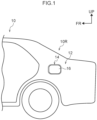
- Fig. 1 shows a simplified side view of a rear portion 10R of a car 10, which serves as a vehicle in which the fuel inlet structure for a vehicle according to the present exemplary embodiment is employed.
- the car 10 includes a side outer panel 12 that serves as a vehicle body panel.
- the side outer panel 12 structures an outer side portion of the vehicle body.
- a fuel inlet portion 14 is provided at a portion of the side outer panel 12.
- a lid 16 is provided, to be capable of opening and closing, at the vehicle width direction outer side of the fuel inlet portion 14.
- Fig. 2 shows an exploded perspective view of a state in which an inlet box with seal 20 is disassembled from the side outer panel 12 at the fuel inlet portion 14.
- the side outer panel 12 at the fuel inlet portion 14 is provided with a recess portion 12B that is recessed by a step from a general surface 12A of the fuel inlet portion 14, which faces to the vehicle width direction outer side.
- the recess portion 12B includes a step portion 12B1 and a floor wall portion 12B2.
- a mounting aperture 12H for inlet box mounting is formed penetrating through the floor wall portion 12B2.
- Fig. 3 shows the inlet box with seal 20 in a perspective view seen from a different direction from Fig. 2 .
- the inlet box with seal 20 includes an inlet box 22, which is fabricated of resin, and a seal portion 30, which is fabricated of rubber.
- the inlet box 22 is provided with a box portion 24 that is formed in a box shape and is disposed such that a box opening 24A is oriented to a cabin outer side.
- the box portion 24 includes a periphery wall portion 24B, which contains the box opening 24A, and a floor wall portion 24C, which is formed continuously from end portions at the cabin inner side of the periphery wall portion 24B.
- a penetrating hole 24H is formed in the floor wall portion 24C.
- a filler pipe which is not shown in the drawings, is disposed at the penetrating hole 24H. The filler pipe is connected to a fuel tank, which is not shown in the drawings.
- the inlet box 22 is further provided with a flange portion 26, which extends from the whole circumference of a peripheral edge of the box opening 24A.
- the flange portion 26 is arranged along a peripheral edge portion of the mounting aperture 12H of the side outer panel 12 shown in Fig. 2 .
- a plural number (for example, four) of engaging portions 28A are provided at the outer periphery side of the periphery wall portion 24B of the box portion 24.
- Each engaging portion 28A is a component that may be understood as an engaging pawl.
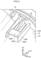
- Fig. 4 is a perspective view in which one of the engaging portions 28A provided at the inlet box 22 is magnified and seen in a view from a different direction from Fig. 3 .
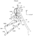
- Fig. 5 is a magnified sectional diagram showing the engaging portion 28A and surrounding portions thereof in a state in which the inlet box 22 is attached to the side outer panel 12, in a section cut at a section position corresponding to line 5-5 in Fig. 3 .
- the engaging portion 28A is cantilevered from a base portion 28B that is formed integrally at an outer face side of the periphery wall portion 24B.
- the base portion 28B is provided with a pair of side wall portions 28B1 and a connecting wall portion 28B2.
- the side wall portions 28B1 protrude from the outer face of the periphery wall portion 24B.
- the connecting wall portion 28B2 connects portions of protrusion direction distal end portions of the pair of side wall portions 28B1 with one another.
- the pair of side wall portions 28B1 extend in a direction orthogonal to an inner face of the flange portion 26, and are formed to be, for example, integrally continuous with the flange portion 26.
- the connecting wall portion 28B2 is specified to be at a position separated from the flange portion 26.
- the engaging portion 28A extends in the direction orthogonal to the inner face of the flange portion 26 and is formed to be integrally continuous with the connecting wall portion 28B2.
- the engaging portion 28A is provided with a base plate portion 28A1 and a protrusion portion 28A2.
- the base plate portion 28A1 is disposed so as to oppose the outer face of the periphery wall portion 24B.
- the protrusion portion 28A2 protrudes to the opposite side of the base plate portion 28A1 from the side thereof at which the periphery wall portion 24B is disposed.
- the protrusion portion 28A2 is provided at a width direction central portion of the base plate portion 28A1 (a central portion in a short side direction intersecting the direction of extension of the base plate portion 28A1).
- a protrusion amount of the protrusion portion 28A2 steadily increases toward the side of the protrusion portion 28A2 at which the flange portion 26 is disposed.
- an inner face 28AX of a region at the protrusion distal end side of the protrusion portion 28A2 faces to the side thereof at which the flange portion 26 is disposed.
- the inner face 28AX is angled a little to the opposite side from the side thereof at which the flange portion 26 is disposed.
- the engaging portion 28A is resiliently deformable, and a free end side thereof is displaceable up and down.
- the box portion 24 of the inlet box 22 is inserted into the mounting aperture 12H of the side outer panel 12 from the vehicle outer side and, while a protrusion distal end 28AT of each protrusion portion 28A2 is displaced up or down, the box portion 24 is inserted to the vehicle inner side beyond the mounting aperture 12H of the side outer panel 12.
- the engaging portions 28A are engaged at the mounting aperture 12H of the side outer panel 12.
- the inlet box 22 is attached to the side outer panel 12 by the plural engaging portions 28A engaging at the mounting aperture 12H of the side outer panel 12.
- the seal portion 30 to be disposed at the vehicle outer side of the side outer panel 12 is provided at the distal end side of the flange portion 26 of the inlet box 22.
- the seal portion 30 is molded integrally with the inlet box 22 (by two-shot molding), and forms a seal between the flange portion 26 of the inlet box 22 and the side outer panel 12 along the whole circumference.
- the seal portion 30 is a double seal structure provided with an inner seal portion 32 and an outer seal portion 34.
- the inner seal portion 32 and the outer seal portion 34 are both provided in correspondence with the whole circumference of the flange portion 26.
- the inner seal portion 32 is in contact with a region at the peripheral edge side of the mounting aperture 12H of the side outer panel 12 along the whole circumference. As shown in Fig. 5 , from a proximal end portion 32A of the inner seal portion 32 toward the side of the recess portion 12B of the side outer panel 12 at which the floor wall portion 12B2 is formed, the inner seal portion 32 is angled to the opposite side from the side thereof at which the mounting aperture 12H is formed. At the distal end side of the inner seal portion 32, the inner seal portion 32 is curved to the opposite side from the side at which the mounting aperture 12H is formed, and the inner seal portion 32 presses against the floor wall portion 12B2 of the recess portion 12B of the side outer panel 12.
- the outer seal portion 34 is in contact with the side outer panel 12 in a region further from the peripheral edge of the mounting aperture 12H than the inner seal portion 32 is. From a proximal end portion 34A of the outer seal portion 34 toward the side at which the step portion 12B1 of the side outer panel 12 is formed, the outer seal portion 34 is angled slightly to the opposite side from the side thereof at which the floor wall portion 12B2 is formed. At the distal end side of the outer seal portion 34, the outer seal portion 34 is curved to the opposite side from the side at which the floor wall portion 12B2 is formed, and the outer seal portion 34 presses against the step portion 12B1 of the side outer panel 12.
- a drain portion 34H for drainage is formed penetrating through a portion of a region of the outer seal portion 34 that is disposed at the vehicle lower side relative to the inner seal portion 32.
- a formation position of the drain portion 34H in the vehicle front-and-rear direction is in, for example, a region encompassing a vehicle front-and-rear direction central position of the outer seal portion 34.
- the drain portion 34H is open to the vehicle lower side and is formed as a substantially semicircular notch portion in an elevation view.
- Fig. 6 is a magnified sectional diagram showing the drain portion 34H and surrounding portions thereof in the state in which the inlet box 22 is attached to the side outer panel 12, in a section cut at a section position corresponding to line 6-6 in Fig. 3 .
- the seal portion 30 is provided with a seal connecting portion 36 that integrally connects the proximal end portion 32A of the inner seal portion 32 with the proximal end portion 34A of the outer seal portion 34.
- a water-catching portion 38 is provided in a portion of the whole circumference of the seal portion 30 that is a lower portion 30A in the vehicle vertical direction. As shown in Fig. 6 , the water-catching portion 38 projects from the seal connecting portion 36, which is a region between the proximal end portion 32A of the inner seal portion 32 and the proximal end portion 34A of the outer seal portion 34, to a region encompassing an area between the drain portion 34H and the inner seal portion 32. As seen from an elevation view side of the inlet box 22 shown in Fig. 3 , the water-catching portion 38 is disposed in a range encompassing a range in a left-and-right direction that corresponds to the drain portion 34H.
- the water-catching portion 38 is capable of stopping water that passes through the drain portion 34H from the vehicle outer side.
- the range in which the water-catching portion 38 is disposed in the left-and-right direction is, more specifically, a range constituted by a range corresponding to the drain portion 34H and predetermined ranges continuing from both sides thereof (the ranges of two side regions 38S depicted by dotted lines in Fig. 3 , which are ranges with widths several times a width of the drain portion 34H).
- the water-catching portion 38 is formed as a plate-shaped portion that integrally projects from the seal connecting portion 36. From a proximal end side of the water-catching portion 38 toward the vehicle lower side, the water-catching portion 38 is angled to the cabin inner side thereof. At the distal end side thereof, the water-catching portion 38 is curved to the opposite side from the side thereof at which the inner seal portion 32 is disposed, and presses against the side outer panel 12. That is, the water-catching portion 38 according to the present exemplary embodiment may be understood as a component that serves as a middle seal portion forming a seal with a different region from the inner seal portion 32 and the outer seal portion 34.
- the inner seal portion 32, outer seal portion 34 and water-catching portion 38 shown in Fig. 5 and Fig. 6 are pressed against the side outer panel 12 by the engagement illustrated in Fig. 5 of the engaging portions 28A at the mounting aperture 12H of the side outer panel 12.
- shapes of the inner seal portion 32, outer seal portion 34 and water-catching portion 38 if the same were not pressing against the side outer panel 12 are illustrated by two-dot chain lines.
- the seal portion 30 that is disposed at the vehicle outer side of the side outer panel 12 is provided at the distal end side of the flange portion 26 of the inlet box 22.
- the seal portion 30 forms seals between the flange portion 26 of the inlet box 22 and the side outer panel 12 along the whole circumference.
- the inner seal portion 32 of the seal portion 30 is provided in correspondence with the whole circumference of the flange portion 26 of the inlet box 22, and is in contact with the region at the peripheral edge side of the mounting aperture 12H of the side outer panel 12 along the whole circumference.
- the outer seal portion 34 of the seal portion 30 is provided in correspondence with the whole circumference of the flange portion 26 of the inlet box 22, and is in contact with the side outer panel 12 in the region that is further from the peripheral edge of the mounting aperture 12H than the inner seal portion 32. Therefore, direct impact against the inner seal portion 32 by high-pressure water, for example, during car washing may be prevented by the outer seal portion 34. Thus, a risk of water ingressing into the cabin between the inner seal portion 32 and the side outer panel 12 may be reduced.
- the drain portion 34H for drainage is formed penetrating through the portion of the region of the outer seal portion 34 that is disposed at the vehicle lower side relative to the inner seal portion 32. Therefore, water that enters to between the outer seal portion 34 and the inner seal portion 32 may drain through the drain portion 34H.
- the water-catching portion 38 is provided at the seal portion 30 in the portion of the whole circumference of the seal portion 30 that is the lower portion 30A in the vehicle vertical direction. As shown in Fig. 6 , the water-catching portion 38 projects from the region between the proximal end portion 32A of the inner seal portion 32 and the proximal end portion 34A of the outer seal portion 34 to the region encompassing the area between the drain portion 34H and the inner seal portion 32. The water-catching portion 38 stops water that passes through the drain portion 34H from the vehicle outer side.
- the range in which the water-catching portion 38 is disposed in the left-and-right direction when seen from the elevation view side of the inlet box 22 is constituted by the range corresponding to the drain portion 34H and the predetermined ranges continuing from both sides of that range (which are ranges with widths several times the width of the drain portion 34H). Therefore, watertightness is at a very high level. Conversely, because the water-catching portion 38 is specified in a limited range of the lower portion 30A of the seal portion 30 in the length direction, excellent drainage through the drain portion 34H may be achieved.
- the proximal end portion 32A of the inner seal portion 32 and the proximal end portion 34A of the outer seal portion 34 are integrally connected by the seal connecting portion 36, and the water-catching portion 38 projects integrally from the seal connecting portion 36. Therefore, formation of a gap between the proximal end side of the water-catching portion 38 and the seal connecting portion 36 may be prevented. Thus, ingression of water as a result of this kind of gap may be prevented.
- the water-catching portion 38 is angled to the cabin inner side thereof.
- the water-catching portion 38 is curved to the opposite side from the side thereof at which the inner seal portion 32 is formed, and the distal end side presses against the side outer panel 12. Therefore, surface pressure of a region at which the water-catching portion 38 is in contact with the side outer panel 12 may be raised, while abutting of the water-catching portion 38 against the inner seal portion 32 is avoided. Therefore, functioning of the inner seal portion 32 may be excellently maintained even while ingression of water between contact portions of the water-catching portion 38 and the side outer panel 12 is suppressed effectively.
- the plural engaging portions 28A that engage at the mounting aperture 12H of the side outer panel 12 are provided at the outer periphery side of the periphery wall portion 24B of the box portion 24 of the inlet box 22.
- the inlet box 22 is attached to the side outer panel 12 by the plural engaging portions 28A engaging at the mounting aperture 12H of the side outer panel 12.
- ingression of water into the cabin may be prevented or suppressed even though the drain portion 34H is formed in a portion of the outer seal portion 34.
- the seal portion 30 is formed integrally with the inlet box 22.
- a seal portion may be formed as a separate body from an inlet box 22 and tightly fitted to the distal end side of a flange portion 26 of the inlet box 22.
- the water-catching portion 38 projects integrally from the seal connecting portion 36.
- a water-catching portion may be formed as a separate body from one or both of an inner seal portion 32 and an outer seal portion 34, and may be engaged with the one or both of the same.
- a structure may be employed in which a distal end portion of a water-catching portion abuts against a vehicle body panel (the side outer panel 12) without being curved.
- a structure may be employed in which a distal end portion of a water-catching portion is slightly apart from a vehicle body panel (the side outer panel 12).
- a structure may be employed in which a flange portion of an inlet box is attached to a vehicle body panel (the side outer panel 12) by fastenings.
Landscapes
- Engineering & Computer Science (AREA)
- Life Sciences & Earth Sciences (AREA)
- Sustainable Development (AREA)
- Sustainable Energy (AREA)
- Chemical & Material Sciences (AREA)
- Combustion & Propulsion (AREA)
- Transportation (AREA)
- Mechanical Engineering (AREA)
- Body Structure For Vehicles (AREA)
- Cooling, Air Intake And Gas Exhaust, And Fuel Tank Arrangements In Propulsion Units (AREA)
- Seal Device For Vehicle (AREA)
Abstract
Description
- The present disclosure relates to a fuel inlet structure of a vehicle.
- A structure is known (for example, see
Fig. 5 in Japanese Patent Application Laid-Open (JP-A) No. 2020-138618 - Although not explicitly stated in
JP-A No. 2020-138618 - However, with this structure, if high-pressure water enters directly through the drain portion, for example, during car washing, the high-pressure water may deform the inner seal portion and ingress into a vehicle cabin.
- In consideration of the circumstances described above, an object of the present disclosure is to provide a fuel inlet structure of a vehicle that may prevent or suppress ingression of water into a cabin even when a drain portion is formed in a portion of an outer seal portion.
- A fuel inlet structure of a vehicle according to a first aspect of the present disclosure includes: a vehicle body panel, a mounting aperture for inlet box mounting penetrating through the vehicle body panel; an inlet box attached to the vehicle body panel, the inlet box including: a box portion, the box portion being formed in a box shape and disposed such that a box opening thereof is oriented toward a cabin outer side, a penetrating hole being formed in a floor wall portion of the box portion, and a flange portion, the flange portion extending from a whole circumference of a peripheral edge of the box opening and being disposed along a peripheral edge portion of the mounting aperture of the vehicle body panel; and a seal portion, the seal portion being provided at a distal end side of the flange portion and disposed at the cabin outer side of the vehicle body panel, the seal portion forming a seal between the flange portion and the vehicle body panel along the whole circumference of the flange portion. The seal portion includes: an inner seal portion provided in correspondence with the whole circumference of the flange portion, the inner seal portion being in contact with a region at a peripheral edge side of the mounting aperture of the vehicle body panel along the whole circumference of the flange portion; an outer seal portion provided in correspondence with the whole circumference of the flange portion, the outer seal portion being in contact with the vehicle body panel in a region further from the peripheral edge of the mounting aperture than the inner seal portion, and a drain portion for drainage being formed penetrating through a portion of a region of the outer seal portion that is disposed at a vehicle lower side relative to the inner seal portion; and a water catching portion, the water catching portion, in a portion of the whole circumference of the seal portion that is a lower portion in the vehicle vertical direction, projecting from a region between a proximal end portion of the inner seal portion and a proximal end portion of the outer seal portion to a region encompassing an area between the drain portion and the inner seal portion, the water-catching portion being configured to stop water that passes through the drain portion from a vehicle outer side.
- According to the structure described above, the seal portion disposed at the vehicle outer side of the vehicle body panel is provided at the distal end side of the flange portion of the inlet box. This seal portion forms a seal between the flange portion of the inlet box and the vehicle body panel along the whole circumference. The inner seal portion of the seal portion is provided in correspondence with the whole circumference of the flange portion of the inlet box, and is in contact with the region at the peripheral edge side of the mounting aperture of the vehicle body panel along the whole circumference. The outer seal portion of the seal portion is provided in correspondence with the whole circumference of the flange portion of the inlet box, and is in contact with the vehicle body panel in the region that is further from the peripheral edge of the mounting aperture than the inner seal portion is. Therefore, direct impact against the inner seal portion by high-pressure water, for example, during car washing may be prevented by the outer seal portion. Thus, a risk of water ingressing into the cabin from between the inner seal portion and the outer seal portion may be reduced.
- The drain portion for drainage is formed penetrating through a portion of the region of the outer seal portion that is disposed at the vehicle lower side relative to the inner seal portion. Therefore, water that enters to between the outer seal portion and the inner seal portion may drain through the drain portion. In the portion of the whole circumference of the seal portion that is a lower portion in the vehicle vertical direction, the water-catching portion of the seal portion projects from the region between the proximal end portion of the inner seal portion and the proximal end portion of the outer seal portion to the region encompassing the area between the drain portion and the inner seal portion. The water-catching portion stops water that has passed through the drain portion from the vehicle outer side. Therefore, direct impact against the inner seal portion by high-pressure water that passes through the drain portion, for example, during car washing may be prevented by the water-catching portion. Thus, the risk of water ingressing into the cabin between the inner seal portion and the vehicle body panel may be further reduced.
- In a fuel inlet structure of a vehicle according to a second aspect of the present disclosure, the structure of the first aspect further includes a seal connecting portion, the seal connecting portion connecting the proximal end portion of the inner seal portion with the proximal end portion of the outer seal portion, wherein the water-catching portion projects integrally from the seal connecting portion.
- According to the structure described above, formation of a gap between the proximal end side of the water-catching portion and the seal connecting portion may be prevented. Thus, ingression of water as a result of this kind of gap may be prevented.
- In a fuel inlet structure of a vehicle according to a third aspect of the present disclosure, in the structure of the first aspect or the second aspect, from a proximal end side of the water-catching portion toward the vehicle lower side, the water-catching portion is angled to a cabin inner side thereof, a distal end side of the water-catching portion is curved to an opposite side from a side thereof at which the inner seal portion is disposed, and the distal end side of the water-catching portion presses against the vehicle body panel.
- According to the structure described above, surface pressure of a region at which the water-catching portion is in contact with the vehicle body panel may be raised, while abutting of the water-catching portion against the inner seal portion is avoided. Therefore, functioning of the inner seal portion may be excellently maintained even while ingression of water between contact portions of the water-catching portion and the vehicle body panel is suppressed effectively.
- In a fuel inlet structure of a vehicle according to a fourth aspect of the present disclosure, the structure of any one of the first to third aspects further includes plural engaging portions, the plural engaging portions being provided at an outer periphery side of a periphery wall portion of the box portion, the engaging portions engaging at the mounting aperture of the vehicle body panel, and engagement of the plural engaging portions at the mounting aperture of the vehicle body panel attaching the inlet box to the vehicle body panel.
- According to the structure described above, there is no need to form fastening holes penetrating through the flange portion of the inlet box and portions of the vehicle body panel surrounding the mounting aperture. Therefore, there is no need to specify that positions of the inner seal portion in an elevation view of the inlet box are at the opposite side of the fastening holes from positions of the outer seal portion, sandwiching the fastening holes. Thus, a separation distance between the outer seal portion and the inner seal portion may be reduced along the whole circumference. If the separation distance between the outer seal portion and the inner seal portion is reduced along the whole circumference, then when high-pressure water passes through the drain portion and ingresses to between the outer seal portion and the inner seal portion during, for example, car washing, an amount of water that is initially retained is reduced, which is disadvantageous for suppressing ingression of water to the cabin inner side. However, because the water-catching portion is provided in the present disclosure, high-pressure water passing through the drain portion and directly impacting against the inner seal portion during car washing may be prevented by the water-catching portion. Thus, ingression of water to the cabin inner side may be suppressed.
- As described above, according to the fuel inlet structure of a vehicle of the present disclosure, an excellent effect is provided in that ingression of water into a cabin may be prevented or suppressed even when a drain portion is formed in a portion of an outer seal portion.
- Exemplary embodiments of the present disclosure will be described in detail based on the following figures, wherein:
-
Fig. 1 is a simplified side view showing a rear portion of a car at which a fuel inlet structure of a vehicle according to an exemplary embodiment of the present disclosure is employed; -
Fig. 2 is an exploded perspective view showing a state in which an inlet box with seal is disassembled from a side outer panel ofFig. 1 ; -
Fig. 3 is a perspective view showing the inlet box with seal ofFig. 2 in a view seen from a different direction fromFig. 2 ; -
Fig. 4 is a perspective view showing an engaging portion provided at the inlet box ofFig. 3 , magnified in a view seen from a different direction fromFig. 3 ; -
Fig. 5 is a magnified sectional diagram showing the engaging portion and surrounding portions thereof in a state in which the inlet box is attached to the side outer panel, in a section cut at a section position corresponding to line 5-5 inFig. 3 ; and -
Fig. 6 is a magnified sectional diagram showing a drain portion and surrounding portions thereof in the state in which the inlet box is attached to the side outer panel, in a section cut at a section position corresponding to line 6-6 inFig. 3 . - A fuel inlet structure of a vehicle according to an exemplary embodiment of the present disclosure is described using
Fig. 1 to Fig. 6 . An arrow FR that is shown as appropriate in these drawings indicates a vehicle front side, an arrow UP indicates a vehicle upper side, and an arrow OUT indicates a vehicle width direction outer side. -
Fig. 1 shows a simplified side view of arear portion 10R of acar 10, which serves as a vehicle in which the fuel inlet structure for a vehicle according to the present exemplary embodiment is employed. As shown inFig. 1 , thecar 10 includes a sideouter panel 12 that serves as a vehicle body panel. The sideouter panel 12 structures an outer side portion of the vehicle body. Afuel inlet portion 14 is provided at a portion of the sideouter panel 12. Alid 16 is provided, to be capable of opening and closing, at the vehicle width direction outer side of thefuel inlet portion 14. -
Fig. 2 shows an exploded perspective view of a state in which an inlet box withseal 20 is disassembled from the sideouter panel 12 at thefuel inlet portion 14. As shown inFig. 2 , the sideouter panel 12 at thefuel inlet portion 14 is provided with arecess portion 12B that is recessed by a step from ageneral surface 12A of thefuel inlet portion 14, which faces to the vehicle width direction outer side. Therecess portion 12B includes a step portion 12B1 and a floor wall portion 12B2. Amounting aperture 12H for inlet box mounting is formed penetrating through the floor wall portion 12B2. -
Fig. 3 shows the inlet box withseal 20 in a perspective view seen from a different direction fromFig. 2 . As illustrated inFig. 2 andFig. 3 , the inlet box withseal 20 includes aninlet box 22, which is fabricated of resin, and aseal portion 30, which is fabricated of rubber. - The
inlet box 22 is provided with abox portion 24 that is formed in a box shape and is disposed such that a box opening 24A is oriented to a cabin outer side. Thebox portion 24 includes aperiphery wall portion 24B, which contains the box opening 24A, and afloor wall portion 24C, which is formed continuously from end portions at the cabin inner side of theperiphery wall portion 24B. A penetratinghole 24H is formed in thefloor wall portion 24C. A filler pipe, which is not shown in the drawings, is disposed at the penetratinghole 24H. The filler pipe is connected to a fuel tank, which is not shown in the drawings. Theinlet box 22 is further provided with aflange portion 26, which extends from the whole circumference of a peripheral edge of thebox opening 24A. Theflange portion 26 is arranged along a peripheral edge portion of the mountingaperture 12H of the sideouter panel 12 shown inFig. 2 . - As shown in
Fig. 3 , a plural number (for example, four) of engagingportions 28A are provided at the outer periphery side of theperiphery wall portion 24B of thebox portion 24. Each engagingportion 28A is a component that may be understood as an engaging pawl.Fig. 4 is a perspective view in which one of the engagingportions 28A provided at theinlet box 22 is magnified and seen in a view from a different direction fromFig. 3 .Fig. 5 is a magnified sectional diagram showing the engagingportion 28A and surrounding portions thereof in a state in which theinlet box 22 is attached to the sideouter panel 12, in a section cut at a section position corresponding to line 5-5 inFig. 3 . - As shown in
Fig. 4 andFig. 5 , the engagingportion 28A is cantilevered from abase portion 28B that is formed integrally at an outer face side of theperiphery wall portion 24B. As shown inFig. 4 , thebase portion 28B is provided with a pair of side wall portions 28B1 and a connecting wall portion 28B2. The side wall portions 28B1 protrude from the outer face of theperiphery wall portion 24B. The connecting wall portion 28B2 connects portions of protrusion direction distal end portions of the pair of side wall portions 28B1 with one another. The pair of side wall portions 28B1 extend in a direction orthogonal to an inner face of theflange portion 26, and are formed to be, for example, integrally continuous with theflange portion 26. The connecting wall portion 28B2 is specified to be at a position separated from theflange portion 26. - The engaging
portion 28A extends in the direction orthogonal to the inner face of theflange portion 26 and is formed to be integrally continuous with the connecting wall portion 28B2. The engagingportion 28A is provided with a base plate portion 28A1 and a protrusion portion 28A2. The base plate portion 28A1 is disposed so as to oppose the outer face of theperiphery wall portion 24B. The protrusion portion 28A2 protrudes to the opposite side of the base plate portion 28A1 from the side thereof at which theperiphery wall portion 24B is disposed. The protrusion portion 28A2 is provided at a width direction central portion of the base plate portion 28A1 (a central portion in a short side direction intersecting the direction of extension of the base plate portion 28A1). A protrusion amount of the protrusion portion 28A2 steadily increases toward the side of the protrusion portion 28A2 at which theflange portion 26 is disposed. As shown inFig. 5 , an inner face 28AX of a region at the protrusion distal end side of the protrusion portion 28A2 faces to the side thereof at which theflange portion 26 is disposed. In the direction in which the protrusion portion 28A2 protrudes from the base plate portion 28A1, the inner face 28AX is angled a little to the opposite side from the side thereof at which theflange portion 26 is disposed. - The engaging
portion 28A is resiliently deformable, and a free end side thereof is displaceable up and down. Thebox portion 24 of theinlet box 22 is inserted into the mountingaperture 12H of the sideouter panel 12 from the vehicle outer side and, while a protrusion distal end 28AT of each protrusion portion 28A2 is displaced up or down, thebox portion 24 is inserted to the vehicle inner side beyond the mountingaperture 12H of the sideouter panel 12. Hence, the engagingportions 28A are engaged at the mountingaperture 12H of the sideouter panel 12. In the present exemplary embodiment, theinlet box 22 is attached to the sideouter panel 12 by the pluralengaging portions 28A engaging at the mountingaperture 12H of the sideouter panel 12. - The
seal portion 30 to be disposed at the vehicle outer side of the sideouter panel 12 is provided at the distal end side of theflange portion 26 of theinlet box 22. Theseal portion 30 is molded integrally with the inlet box 22 (by two-shot molding), and forms a seal between theflange portion 26 of theinlet box 22 and the sideouter panel 12 along the whole circumference. As illustrated inFig. 3 andFig. 5 , theseal portion 30 is a double seal structure provided with aninner seal portion 32 and anouter seal portion 34. Theinner seal portion 32 and theouter seal portion 34 are both provided in correspondence with the whole circumference of theflange portion 26. - The
inner seal portion 32 is in contact with a region at the peripheral edge side of the mountingaperture 12H of the sideouter panel 12 along the whole circumference. As shown inFig. 5 , from aproximal end portion 32A of theinner seal portion 32 toward the side of therecess portion 12B of the sideouter panel 12 at which the floor wall portion 12B2 is formed, theinner seal portion 32 is angled to the opposite side from the side thereof at which the mountingaperture 12H is formed. At the distal end side of theinner seal portion 32, theinner seal portion 32 is curved to the opposite side from the side at which the mountingaperture 12H is formed, and theinner seal portion 32 presses against the floor wall portion 12B2 of therecess portion 12B of the sideouter panel 12. - The
outer seal portion 34 is in contact with the sideouter panel 12 in a region further from the peripheral edge of the mountingaperture 12H than theinner seal portion 32 is. From aproximal end portion 34A of theouter seal portion 34 toward the side at which the step portion 12B1 of the sideouter panel 12 is formed, theouter seal portion 34 is angled slightly to the opposite side from the side thereof at which the floor wall portion 12B2 is formed. At the distal end side of theouter seal portion 34, theouter seal portion 34 is curved to the opposite side from the side at which the floor wall portion 12B2 is formed, and theouter seal portion 34 presses against the step portion 12B1 of the sideouter panel 12. - As shown in
Fig. 3 , adrain portion 34H for drainage is formed penetrating through a portion of a region of theouter seal portion 34 that is disposed at the vehicle lower side relative to theinner seal portion 32. A formation position of thedrain portion 34H in the vehicle front-and-rear direction is in, for example, a region encompassing a vehicle front-and-rear direction central position of theouter seal portion 34. Thedrain portion 34H is open to the vehicle lower side and is formed as a substantially semicircular notch portion in an elevation view. -
Fig. 6 is a magnified sectional diagram showing thedrain portion 34H and surrounding portions thereof in the state in which theinlet box 22 is attached to the sideouter panel 12, in a section cut at a section position corresponding to line 6-6 inFig. 3 . As shown inFig. 5 andFig. 6 , theseal portion 30 is provided with aseal connecting portion 36 that integrally connects theproximal end portion 32A of theinner seal portion 32 with theproximal end portion 34A of theouter seal portion 34. - As shown in
Fig. 3 , a water-catchingportion 38 is provided in a portion of the whole circumference of theseal portion 30 that is alower portion 30A in the vehicle vertical direction. As shown inFig. 6 , the water-catchingportion 38 projects from theseal connecting portion 36, which is a region between theproximal end portion 32A of theinner seal portion 32 and theproximal end portion 34A of theouter seal portion 34, to a region encompassing an area between thedrain portion 34H and theinner seal portion 32. As seen from an elevation view side of theinlet box 22 shown inFig. 3 , the water-catchingportion 38 is disposed in a range encompassing a range in a left-and-right direction that corresponds to thedrain portion 34H. Thus, the water-catchingportion 38 is capable of stopping water that passes through thedrain portion 34H from the vehicle outer side. When theinlet box 22 is viewed from the elevation view side, the range in which the water-catchingportion 38 is disposed in the left-and-right direction is, more specifically, a range constituted by a range corresponding to thedrain portion 34H and predetermined ranges continuing from both sides thereof (the ranges of twoside regions 38S depicted by dotted lines inFig. 3 , which are ranges with widths several times a width of thedrain portion 34H). - As shown in
Fig. 6 , the water-catchingportion 38 is formed as a plate-shaped portion that integrally projects from theseal connecting portion 36. From a proximal end side of the water-catchingportion 38 toward the vehicle lower side, the water-catchingportion 38 is angled to the cabin inner side thereof. At the distal end side thereof, the water-catchingportion 38 is curved to the opposite side from the side thereof at which theinner seal portion 32 is disposed, and presses against the sideouter panel 12. That is, the water-catchingportion 38 according to the present exemplary embodiment may be understood as a component that serves as a middle seal portion forming a seal with a different region from theinner seal portion 32 and theouter seal portion 34. - The
inner seal portion 32,outer seal portion 34 and water-catchingportion 38 shown inFig. 5 andFig. 6 are pressed against the sideouter panel 12 by the engagement illustrated inFig. 5 of the engagingportions 28A at the mountingaperture 12H of the sideouter panel 12. InFig. 5 andFig. 6 , shapes of theinner seal portion 32,outer seal portion 34 and water-catchingportion 38 if the same were not pressing against the sideouter panel 12 are illustrated by two-dot chain lines. - Now, operation and effects of the above exemplary embodiment are described.
- As shown in
Fig. 5 andFig. 6 , theseal portion 30 that is disposed at the vehicle outer side of the sideouter panel 12 is provided at the distal end side of theflange portion 26 of theinlet box 22. Theseal portion 30 forms seals between theflange portion 26 of theinlet box 22 and the sideouter panel 12 along the whole circumference. Theinner seal portion 32 of theseal portion 30 is provided in correspondence with the whole circumference of theflange portion 26 of theinlet box 22, and is in contact with the region at the peripheral edge side of the mountingaperture 12H of the sideouter panel 12 along the whole circumference. Theouter seal portion 34 of theseal portion 30 is provided in correspondence with the whole circumference of theflange portion 26 of theinlet box 22, and is in contact with the sideouter panel 12 in the region that is further from the peripheral edge of the mountingaperture 12H than theinner seal portion 32. Therefore, direct impact against theinner seal portion 32 by high-pressure water, for example, during car washing may be prevented by theouter seal portion 34. Thus, a risk of water ingressing into the cabin between theinner seal portion 32 and the sideouter panel 12 may be reduced. - As shown in
Fig. 3 andFig. 6 , thedrain portion 34H for drainage is formed penetrating through the portion of the region of theouter seal portion 34 that is disposed at the vehicle lower side relative to theinner seal portion 32. Therefore, water that enters to between theouter seal portion 34 and theinner seal portion 32 may drain through thedrain portion 34H. - The water-catching
portion 38 is provided at theseal portion 30 in the portion of the whole circumference of theseal portion 30 that is thelower portion 30A in the vehicle vertical direction. As shown inFig. 6 , the water-catchingportion 38 projects from the region between theproximal end portion 32A of theinner seal portion 32 and theproximal end portion 34A of theouter seal portion 34 to the region encompassing the area between thedrain portion 34H and theinner seal portion 32. The water-catchingportion 38 stops water that passes through thedrain portion 34H from the vehicle outer side. Therefore, direct impact against theinner seal portion 32 by high-pressure water passing through thedrain portion 34H during car washing may be prevented by the water-catchingportion 38, and the risk of water ingressing into the cabin between theinner seal portion 32 and the sideouter panel 12 may be further reduced. Thus, watertightness is excellently assured. - In the present exemplary embodiment, as shown in
Fig. 3 , the range in which the water-catchingportion 38 is disposed in the left-and-right direction when seen from the elevation view side of theinlet box 22 is constituted by the range corresponding to thedrain portion 34H and the predetermined ranges continuing from both sides of that range (which are ranges with widths several times the width of thedrain portion 34H). Therefore, watertightness is at a very high level. Conversely, because the water-catchingportion 38 is specified in a limited range of thelower portion 30A of theseal portion 30 in the length direction, excellent drainage through thedrain portion 34H may be achieved. - In the present exemplary embodiment, as shown in
Fig. 6 , theproximal end portion 32A of theinner seal portion 32 and theproximal end portion 34A of theouter seal portion 34 are integrally connected by theseal connecting portion 36, and the water-catchingportion 38 projects integrally from theseal connecting portion 36. Therefore, formation of a gap between the proximal end side of the water-catchingportion 38 and theseal connecting portion 36 may be prevented. Thus, ingression of water as a result of this kind of gap may be prevented. - In the present exemplary embodiment, from the proximal end side of the water-catching
portion 38 toward the vehicle lower side, the water-catchingportion 38 is angled to the cabin inner side thereof. At the distal end side thereof, the water-catchingportion 38 is curved to the opposite side from the side thereof at which theinner seal portion 32 is formed, and the distal end side presses against the sideouter panel 12. Therefore, surface pressure of a region at which the water-catchingportion 38 is in contact with the sideouter panel 12 may be raised, while abutting of the water-catchingportion 38 against theinner seal portion 32 is avoided. Therefore, functioning of theinner seal portion 32 may be excellently maintained even while ingression of water between contact portions of the water-catchingportion 38 and the sideouter panel 12 is suppressed effectively. - In the present exemplary embodiment, as shown in
Fig. 3 andFig. 5 , theplural engaging portions 28A that engage at the mountingaperture 12H of the sideouter panel 12 are provided at the outer periphery side of theperiphery wall portion 24B of thebox portion 24 of theinlet box 22. Theinlet box 22 is attached to the sideouter panel 12 by the pluralengaging portions 28A engaging at the mountingaperture 12H of the sideouter panel 12. With this structure, there is no need to form fastening holes penetrating through theflange portion 26 of theinlet box 22 and portions of the sideouter panel 12 surrounding the mountingaperture 12H. Therefore, there is no need to take account of fastening holes when specifying positions of theinner seal portion 32, and a separation distance between theouter seal portion 34 and theinner seal portion 32 may be reduced along the whole circumference. - If the separation distance between the
outer seal portion 34 and theinner seal portion 32 is reduced along the whole circumference, then when high-pressure water passes through thedrain portion 34H shown inFig. 3 andFig. 6 and ingresses to between theouter seal portion 34 and theinner seal portion 32 during, for example, car washing, an amount of water that is initially retained is reduced. This is disadvantageous for suppressing ingression of water to the cabin inner side. However, because the water-catchingportion 38 is provided in the present exemplary embodiment, high-pressure water passing through thedrain portion 34H and directly impacting against theinner seal portion 32 during car washing may be prevented by the water-catchingportion 38. Thus, ingression of water to the cabin inner side may be suppressed. - According to the fuel inlet structure of a vehicle of according to the present exemplary embodiment as described above, ingression of water into the cabin may be prevented or suppressed even though the
drain portion 34H is formed in a portion of theouter seal portion 34. - In the exemplary embodiment described above, the
seal portion 30 is formed integrally with theinlet box 22. However, as a variant example of the exemplary embodiment described above, a seal portion may be formed as a separate body from aninlet box 22 and tightly fitted to the distal end side of aflange portion 26 of theinlet box 22. - In the exemplary embodiment described above, the water-catching
portion 38 projects integrally from theseal connecting portion 36. However, as a variant example of the exemplary embodiment described above, for example, a water-catching portion may be formed as a separate body from one or both of aninner seal portion 32 and anouter seal portion 34, and may be engaged with the one or both of the same. - As a variant example of the exemplary embodiment described above, a structure may be employed in which a distal end portion of a water-catching portion abuts against a vehicle body panel (the side outer panel 12) without being curved. As an alternative variant example, a structure may be employed in which a distal end portion of a water-catching portion is slightly apart from a vehicle body panel (the side outer panel 12).
- As another variant example of the exemplary embodiment described above, a structure may be employed in which a flange portion of an inlet box is attached to a vehicle body panel (the side outer panel 12) by fastenings.
- The exemplary embodiment described above and numerous variant examples mentioned above may be embodied in suitable combinations.
- Above, examples of the present disclosure have been described. The present disclosure is not limited by these descriptions and it will be clear that numerous modifications outside of these descriptions may be embodied within a technical scope not deviating from the gist of the disclosure.
Claims (4)
- A fuel inlet structure of a vehicle, the fuel inlet structure comprising:a vehicle body panel (12), a mounting aperture (12H) for inlet box mounting penetrating through the vehicle body panel;an inlet box (22) attached to the vehicle body panel, the inlet box including:a box portion (24), the box portion being formed in a box shape and disposed such that a box opening (24A) thereof is oriented toward a cabin outer side, a penetrating hole (24H) being formed in a floor wall portion (24C) of the box portion (24), anda flange portion (26), the flange portion extending from a whole circumference of a peripheral edge of the box opening (24A) and being disposed along a peripheral edge portion of the mounting aperture (12H) of the vehicle body panel; anda seal portion (30), the seal portion being provided at a distal end side of the flange portion (26) and disposed at the cabin outer side of the vehicle body panel, the seal portion forming a seal between the flange portion (26) and the vehicle body panel (12) along the whole circumference of the flange portion,wherein the seal portion (30) includes:an inner seal portion (32) provided in correspondence with the whole circumference of the flange portion (26), the inner seal portion being in contact with a region at a peripheral edge side of the mounting aperture (12H) of the vehicle body panel along the whole circumference of the flange portion;an outer seal portion (34) provided in correspondence with the whole circumference of the flange portion (26), the outer seal portion being in contact with the vehicle body panel (12) in a region further from the peripheral edge of the mounting aperture (12H) than the inner seal portion (32), and a drain portion (34H) for drainage being formed penetrating through a portion of a region of the outer seal portion (34) that is disposed at a vehicle lower side relative to the inner seal portion (32); anda water catching portion (38), the water catching portion, in a portion of the whole circumference of the seal portion (30) that is a lower portion in the vehicle vertical direction, projecting from a region between a proximal end portion (32A) of the inner seal portion (32) and a proximal end portion (34A) of the outer seal portion (34) to a region encompassing an area between the drain portion (34H) and the inner seal portion (32), the water-catching portion (38) being configured to stop water that passes through the drain portion from a vehicle outer side.
- The fuel inlet structure of a vehicle according to claim 1, further comprising a seal connecting portion (36), the seal connecting portion connecting the proximal end portion (32A) of the inner seal portion (32) with the proximal end portion (34A) of the outer seal portion (34),
wherein the water-catching portion (38) projects integrally from the seal connecting portion (36). - The fuel inlet structure of a vehicle according to claim 1 or claim 2, wherein:from a proximal end side of the water-catching portion (38) toward the vehicle lower side, the water-catching portion (38) is angled to a cabin inner side thereof,a distal end side of the water-catching portion (38) is curved to an opposite side from a side thereof at which the inner seal portion (32) is disposed, andthe distal end side of the water-catching portion (38) presses against the vehicle body panel (12).
- The fuel inlet structure of a vehicle according to any one of claims 1-3, further comprising a plurality of engaging portions (28A), the plurality of engaging portions being provided at an outer periphery side of a periphery wall portion (24B) of the box portion (24), the engaging portions (28A) engaging at the mounting aperture (12H) of the vehicle body panel (12), and engagement of the plurality of engaging portions (28A) at the mounting aperture of the vehicle body panel attaching the inlet box (22) to the vehicle body panel.
Applications Claiming Priority (1)
| Application Number | Priority Date | Filing Date | Title |
|---|---|---|---|
| JP2021145615A JP7563343B2 (en) | 2021-09-07 | 2021-09-07 | Vehicle fuel inlet structure |
Publications (2)
| Publication Number | Publication Date |
|---|---|
| EP4155108A1 true EP4155108A1 (en) | 2023-03-29 |
| EP4155108B1 EP4155108B1 (en) | 2024-04-03 |
Family
ID=83192027
Family Applications (1)
| Application Number | Title | Priority Date | Filing Date |
|---|---|---|---|
| EP22189489.2A Active EP4155108B1 (en) | 2021-09-07 | 2022-08-09 | Fuel inlet structure of vehicle |
Country Status (3)
| Country | Link |
|---|---|
| US (1) | US11919385B2 (en) |
| EP (1) | EP4155108B1 (en) |
| JP (1) | JP7563343B2 (en) |
Citations (4)
| Publication number | Priority date | Publication date | Assignee | Title |
|---|---|---|---|---|
| EP2581250A1 (en) * | 2011-05-16 | 2013-04-17 | Toyota Shatai Kabushiki Kaisha | Structure for mounting vehicle inlet box |
| US20140084550A1 (en) * | 2012-09-27 | 2014-03-27 | Toyoda Gosei Co., Ltd. | Sealing structure of fuel inlet box |
| JP2019123465A (en) * | 2018-01-19 | 2019-07-25 | 株式会社Fts | Seal structure of oil supply port box |
| JP2020138618A (en) | 2019-02-27 | 2020-09-03 | トヨタ自動車株式会社 | Vehicle fuel filling port structure |
Family Cites Families (9)
| Publication number | Priority date | Publication date | Assignee | Title |
|---|---|---|---|---|
| JPS5496933U (en) * | 1977-12-20 | 1979-07-09 | ||
| JP2007084043A (en) * | 2005-08-26 | 2007-04-05 | Toyoda Gosei Co Ltd | Covering member |
| JP4731298B2 (en) * | 2005-12-01 | 2011-07-20 | 日野自動車株式会社 | Fuel lid structure |
| US8215333B2 (en) * | 2009-06-16 | 2012-07-10 | Honda Motor Co., Ltd. | Fuel filler assembly |
| EP2628622B1 (en) * | 2010-10-14 | 2016-07-13 | Honda Motor Co., Ltd. | Structure for fuel filler tube opening |
| DE102015221869A1 (en) * | 2015-11-06 | 2017-05-11 | Bayerische Motoren Werke Aktiengesellschaft | motor vehicle |
| JP2018192925A (en) * | 2017-05-18 | 2018-12-06 | ダイキョーニシカワ株式会社 | Fuel case assembly |
| US11541746B2 (en) * | 2018-08-24 | 2023-01-03 | Illinois Tool Works Inc. | Oiling or charging port assembly |
| JP7095755B2 (en) * | 2019-01-17 | 2022-07-05 | 三菱自動車工業株式会社 | vehicle |
-
2021
- 2021-09-07 JP JP2021145615A patent/JP7563343B2/en active Active
-
2022
- 2022-08-09 EP EP22189489.2A patent/EP4155108B1/en active Active
- 2022-08-29 US US17/897,631 patent/US11919385B2/en active Active
Patent Citations (4)
| Publication number | Priority date | Publication date | Assignee | Title |
|---|---|---|---|---|
| EP2581250A1 (en) * | 2011-05-16 | 2013-04-17 | Toyota Shatai Kabushiki Kaisha | Structure for mounting vehicle inlet box |
| US20140084550A1 (en) * | 2012-09-27 | 2014-03-27 | Toyoda Gosei Co., Ltd. | Sealing structure of fuel inlet box |
| JP2019123465A (en) * | 2018-01-19 | 2019-07-25 | 株式会社Fts | Seal structure of oil supply port box |
| JP2020138618A (en) | 2019-02-27 | 2020-09-03 | トヨタ自動車株式会社 | Vehicle fuel filling port structure |
Also Published As
| Publication number | Publication date |
|---|---|
| US11919385B2 (en) | 2024-03-05 |
| JP2023038741A (en) | 2023-03-17 |
| EP4155108B1 (en) | 2024-04-03 |
| JP7563343B2 (en) | 2024-10-08 |
| US20230070591A1 (en) | 2023-03-09 |
Similar Documents
| Publication | Publication Date | Title |
|---|---|---|
| JP5796799B2 (en) | Waterproof connector | |
| US20070271853A1 (en) | Glass run mounting structure | |
| US7862273B2 (en) | Part mounting mechanism | |
| US9190818B2 (en) | Electrical connection box | |
| US6430878B2 (en) | Glass guide | |
| CN215705589U (en) | Glass guide groove of frameless vehicle door | |
| EP1852287B1 (en) | Parting seal for vehicle door | |
| EP4155108A1 (en) | Fuel inlet structure of vehicle | |
| CN105083387A (en) | Cowl cover device | |
| JP7336066B2 (en) | Grommet unit | |
| CN102039936B (en) | Drain plug | |
| JP3967342B2 (en) | Window assembly | |
| KR100899829B1 (en) | Rubber for the door | |
| CN119840396B (en) | External water-cutting components, door waterproofing systems and vehicles | |
| JP5119915B2 (en) | Vehicle cowl grill structure | |
| JP7667004B2 (en) | Water drainage material | |
| JP2018193000A (en) | Vehicle body front part structure | |
| US20250162404A1 (en) | Vehicle lid device | |
| JP7790946B2 (en) | Inlet box | |
| CN218519521U (en) | Partition seal and seal structure of the partition | |
| CN121162129A (en) | Lock catch waterproof cover, lock catch assembly and vehicle | |
| JP2009154834A5 (en) | ||
| CN121005055A (en) | The rear structure of the vehicle and the vehicle | |
| JP2007203767A (en) | Draining structure of vehicle door glass run | |
| CN118876684A (en) | Sealing structure of automobile door |
Legal Events
| Date | Code | Title | Description |
|---|---|---|---|
| PUAI | Public reference made under article 153(3) epc to a published international application that has entered the european phase |
Free format text: ORIGINAL CODE: 0009012 |
|
| STAA | Information on the status of an ep patent application or granted ep patent |
Free format text: STATUS: REQUEST FOR EXAMINATION WAS MADE |
|
| 17P | Request for examination filed |
Effective date: 20220809 |
|
| AK | Designated contracting states |
Kind code of ref document: A1 Designated state(s): AL AT BE BG CH CY CZ DE DK EE ES FI FR GB GR HR HU IE IS IT LI LT LU LV MC MK MT NL NO PL PT RO RS SE SI SK SM TR |
|
| RIC1 | Information provided on ipc code assigned before grant |
Ipc: B60K 15/05 20060101ALI20231013BHEP Ipc: B60K 15/04 20060101AFI20231013BHEP |
|
| GRAP | Despatch of communication of intention to grant a patent |
Free format text: ORIGINAL CODE: EPIDOSNIGR1 |
|
| STAA | Information on the status of an ep patent application or granted ep patent |
Free format text: STATUS: GRANT OF PATENT IS INTENDED |
|
| INTG | Intention to grant announced |
Effective date: 20231204 |
|
| GRAS | Grant fee paid |
Free format text: ORIGINAL CODE: EPIDOSNIGR3 |
|
| GRAA | (expected) grant |
Free format text: ORIGINAL CODE: 0009210 |
|
| STAA | Information on the status of an ep patent application or granted ep patent |
Free format text: STATUS: THE PATENT HAS BEEN GRANTED |
|
| AK | Designated contracting states |
Kind code of ref document: B1 Designated state(s): AL AT BE BG CH CY CZ DE DK EE ES FI FR GB GR HR HU IE IS IT LI LT LU LV MC MK MT NL NO PL PT RO RS SE SI SK SM TR |
|
| REG | Reference to a national code |
Ref country code: CH Ref legal event code: EP |
|
| REG | Reference to a national code |
Ref country code: IE Ref legal event code: FG4D |
|
| REG | Reference to a national code |
Ref country code: DE Ref legal event code: R096 Ref document number: 602022002678 Country of ref document: DE |
|
| P01 | Opt-out of the competence of the unified patent court (upc) registered |
Effective date: 20240419 |
|
| REG | Reference to a national code |
Ref country code: LT Ref legal event code: MG9D |
|
| REG | Reference to a national code |
Ref country code: NL Ref legal event code: MP Effective date: 20240403 |
|
| REG | Reference to a national code |
Ref country code: AT Ref legal event code: MK05 Ref document number: 1671908 Country of ref document: AT Kind code of ref document: T Effective date: 20240403 |
|
| PG25 | Lapsed in a contracting state [announced via postgrant information from national office to epo] |
Ref country code: NL Free format text: LAPSE BECAUSE OF FAILURE TO SUBMIT A TRANSLATION OF THE DESCRIPTION OR TO PAY THE FEE WITHIN THE PRESCRIBED TIME-LIMIT Effective date: 20240403 |
|
| PG25 | Lapsed in a contracting state [announced via postgrant information from national office to epo] |
Ref country code: NL Free format text: LAPSE BECAUSE OF FAILURE TO SUBMIT A TRANSLATION OF THE DESCRIPTION OR TO PAY THE FEE WITHIN THE PRESCRIBED TIME-LIMIT Effective date: 20240403 |
|
| PG25 | Lapsed in a contracting state [announced via postgrant information from national office to epo] |
Ref country code: IS Free format text: LAPSE BECAUSE OF FAILURE TO SUBMIT A TRANSLATION OF THE DESCRIPTION OR TO PAY THE FEE WITHIN THE PRESCRIBED TIME-LIMIT Effective date: 20240803 |
|
| PG25 | Lapsed in a contracting state [announced via postgrant information from national office to epo] |
Ref country code: BG Free format text: LAPSE BECAUSE OF FAILURE TO SUBMIT A TRANSLATION OF THE DESCRIPTION OR TO PAY THE FEE WITHIN THE PRESCRIBED TIME-LIMIT Effective date: 20240403 |
|
| PG25 | Lapsed in a contracting state [announced via postgrant information from national office to epo] |
Ref country code: HR Free format text: LAPSE BECAUSE OF FAILURE TO SUBMIT A TRANSLATION OF THE DESCRIPTION OR TO PAY THE FEE WITHIN THE PRESCRIBED TIME-LIMIT Effective date: 20240403 Ref country code: FI Free format text: LAPSE BECAUSE OF FAILURE TO SUBMIT A TRANSLATION OF THE DESCRIPTION OR TO PAY THE FEE WITHIN THE PRESCRIBED TIME-LIMIT Effective date: 20240403 |
|
| PG25 | Lapsed in a contracting state [announced via postgrant information from national office to epo] |
Ref country code: GR Free format text: LAPSE BECAUSE OF FAILURE TO SUBMIT A TRANSLATION OF THE DESCRIPTION OR TO PAY THE FEE WITHIN THE PRESCRIBED TIME-LIMIT Effective date: 20240704 |
|
| PG25 | Lapsed in a contracting state [announced via postgrant information from national office to epo] |
Ref country code: PT Free format text: LAPSE BECAUSE OF FAILURE TO SUBMIT A TRANSLATION OF THE DESCRIPTION OR TO PAY THE FEE WITHIN THE PRESCRIBED TIME-LIMIT Effective date: 20240805 |
|
| PG25 | Lapsed in a contracting state [announced via postgrant information from national office to epo] |
Ref country code: ES Free format text: LAPSE BECAUSE OF FAILURE TO SUBMIT A TRANSLATION OF THE DESCRIPTION OR TO PAY THE FEE WITHIN THE PRESCRIBED TIME-LIMIT Effective date: 20240403 |
|
| PG25 | Lapsed in a contracting state [announced via postgrant information from national office to epo] |
Ref country code: CZ Free format text: LAPSE BECAUSE OF FAILURE TO SUBMIT A TRANSLATION OF THE DESCRIPTION OR TO PAY THE FEE WITHIN THE PRESCRIBED TIME-LIMIT Effective date: 20240403 |
|
| PG25 | Lapsed in a contracting state [announced via postgrant information from national office to epo] |
Ref country code: AT Free format text: LAPSE BECAUSE OF FAILURE TO SUBMIT A TRANSLATION OF THE DESCRIPTION OR TO PAY THE FEE WITHIN THE PRESCRIBED TIME-LIMIT Effective date: 20240403 |
|
| PG25 | Lapsed in a contracting state [announced via postgrant information from national office to epo] |
Ref country code: PL Free format text: LAPSE BECAUSE OF FAILURE TO SUBMIT A TRANSLATION OF THE DESCRIPTION OR TO PAY THE FEE WITHIN THE PRESCRIBED TIME-LIMIT Effective date: 20240403 |
|
| PG25 | Lapsed in a contracting state [announced via postgrant information from national office to epo] |
Ref country code: LV Free format text: LAPSE BECAUSE OF FAILURE TO SUBMIT A TRANSLATION OF THE DESCRIPTION OR TO PAY THE FEE WITHIN THE PRESCRIBED TIME-LIMIT Effective date: 20240403 |
|
| PG25 | Lapsed in a contracting state [announced via postgrant information from national office to epo] |
Ref country code: PT Free format text: LAPSE BECAUSE OF FAILURE TO SUBMIT A TRANSLATION OF THE DESCRIPTION OR TO PAY THE FEE WITHIN THE PRESCRIBED TIME-LIMIT Effective date: 20240805 Ref country code: PL Free format text: LAPSE BECAUSE OF FAILURE TO SUBMIT A TRANSLATION OF THE DESCRIPTION OR TO PAY THE FEE WITHIN THE PRESCRIBED TIME-LIMIT Effective date: 20240403 Ref country code: NO Free format text: LAPSE BECAUSE OF FAILURE TO SUBMIT A TRANSLATION OF THE DESCRIPTION OR TO PAY THE FEE WITHIN THE PRESCRIBED TIME-LIMIT Effective date: 20240703 Ref country code: LV Free format text: LAPSE BECAUSE OF FAILURE TO SUBMIT A TRANSLATION OF THE DESCRIPTION OR TO PAY THE FEE WITHIN THE PRESCRIBED TIME-LIMIT Effective date: 20240403 Ref country code: IS Free format text: LAPSE BECAUSE OF FAILURE TO SUBMIT A TRANSLATION OF THE DESCRIPTION OR TO PAY THE FEE WITHIN THE PRESCRIBED TIME-LIMIT Effective date: 20240803 Ref country code: HR Free format text: LAPSE BECAUSE OF FAILURE TO SUBMIT A TRANSLATION OF THE DESCRIPTION OR TO PAY THE FEE WITHIN THE PRESCRIBED TIME-LIMIT Effective date: 20240403 Ref country code: GR Free format text: LAPSE BECAUSE OF FAILURE TO SUBMIT A TRANSLATION OF THE DESCRIPTION OR TO PAY THE FEE WITHIN THE PRESCRIBED TIME-LIMIT Effective date: 20240704 Ref country code: FI Free format text: LAPSE BECAUSE OF FAILURE TO SUBMIT A TRANSLATION OF THE DESCRIPTION OR TO PAY THE FEE WITHIN THE PRESCRIBED TIME-LIMIT Effective date: 20240403 Ref country code: ES Free format text: LAPSE BECAUSE OF FAILURE TO SUBMIT A TRANSLATION OF THE DESCRIPTION OR TO PAY THE FEE WITHIN THE PRESCRIBED TIME-LIMIT Effective date: 20240403 Ref country code: CZ Free format text: LAPSE BECAUSE OF FAILURE TO SUBMIT A TRANSLATION OF THE DESCRIPTION OR TO PAY THE FEE WITHIN THE PRESCRIBED TIME-LIMIT Effective date: 20240403 Ref country code: BG Free format text: LAPSE BECAUSE OF FAILURE TO SUBMIT A TRANSLATION OF THE DESCRIPTION OR TO PAY THE FEE WITHIN THE PRESCRIBED TIME-LIMIT Effective date: 20240403 Ref country code: AT Free format text: LAPSE BECAUSE OF FAILURE TO SUBMIT A TRANSLATION OF THE DESCRIPTION OR TO PAY THE FEE WITHIN THE PRESCRIBED TIME-LIMIT Effective date: 20240403 Ref country code: RS Free format text: LAPSE BECAUSE OF FAILURE TO SUBMIT A TRANSLATION OF THE DESCRIPTION OR TO PAY THE FEE WITHIN THE PRESCRIBED TIME-LIMIT Effective date: 20240703 |
|
| REG | Reference to a national code |
Ref country code: DE Ref legal event code: R084 Ref document number: 602022002678 Country of ref document: DE |
|
| REG | Reference to a national code |
Ref country code: DE Ref legal event code: R097 Ref document number: 602022002678 Country of ref document: DE |
|
| PG25 | Lapsed in a contracting state [announced via postgrant information from national office to epo] |
Ref country code: DK Free format text: LAPSE BECAUSE OF FAILURE TO SUBMIT A TRANSLATION OF THE DESCRIPTION OR TO PAY THE FEE WITHIN THE PRESCRIBED TIME-LIMIT Effective date: 20240403 |
|
| PG25 | Lapsed in a contracting state [announced via postgrant information from national office to epo] |
Ref country code: EE Free format text: LAPSE BECAUSE OF FAILURE TO SUBMIT A TRANSLATION OF THE DESCRIPTION OR TO PAY THE FEE WITHIN THE PRESCRIBED TIME-LIMIT Effective date: 20240403 |
|
| PG25 | Lapsed in a contracting state [announced via postgrant information from national office to epo] |
Ref country code: SK Free format text: LAPSE BECAUSE OF FAILURE TO SUBMIT A TRANSLATION OF THE DESCRIPTION OR TO PAY THE FEE WITHIN THE PRESCRIBED TIME-LIMIT Effective date: 20240403 Ref country code: RO Free format text: LAPSE BECAUSE OF FAILURE TO SUBMIT A TRANSLATION OF THE DESCRIPTION OR TO PAY THE FEE WITHIN THE PRESCRIBED TIME-LIMIT Effective date: 20240403 |
|
| PG25 | Lapsed in a contracting state [announced via postgrant information from national office to epo] |
Ref country code: SM Free format text: LAPSE BECAUSE OF FAILURE TO SUBMIT A TRANSLATION OF THE DESCRIPTION OR TO PAY THE FEE WITHIN THE PRESCRIBED TIME-LIMIT Effective date: 20240403 |
|
| PG25 | Lapsed in a contracting state [announced via postgrant information from national office to epo] |
Ref country code: SM Free format text: LAPSE BECAUSE OF FAILURE TO SUBMIT A TRANSLATION OF THE DESCRIPTION OR TO PAY THE FEE WITHIN THE PRESCRIBED TIME-LIMIT Effective date: 20240403 Ref country code: SK Free format text: LAPSE BECAUSE OF FAILURE TO SUBMIT A TRANSLATION OF THE DESCRIPTION OR TO PAY THE FEE WITHIN THE PRESCRIBED TIME-LIMIT Effective date: 20240403 Ref country code: RO Free format text: LAPSE BECAUSE OF FAILURE TO SUBMIT A TRANSLATION OF THE DESCRIPTION OR TO PAY THE FEE WITHIN THE PRESCRIBED TIME-LIMIT Effective date: 20240403 Ref country code: EE Free format text: LAPSE BECAUSE OF FAILURE TO SUBMIT A TRANSLATION OF THE DESCRIPTION OR TO PAY THE FEE WITHIN THE PRESCRIBED TIME-LIMIT Effective date: 20240403 Ref country code: DK Free format text: LAPSE BECAUSE OF FAILURE TO SUBMIT A TRANSLATION OF THE DESCRIPTION OR TO PAY THE FEE WITHIN THE PRESCRIBED TIME-LIMIT Effective date: 20240403 |
|
| PLBE | No opposition filed within time limit |
Free format text: ORIGINAL CODE: 0009261 |
|
| STAA | Information on the status of an ep patent application or granted ep patent |
Free format text: STATUS: NO OPPOSITION FILED WITHIN TIME LIMIT |
|
| 26N | No opposition filed |
Effective date: 20250106 |
|
| PG25 | Lapsed in a contracting state [announced via postgrant information from national office to epo] |
Ref country code: LU Free format text: LAPSE BECAUSE OF NON-PAYMENT OF DUE FEES Effective date: 20240809 |
|
| PG25 | Lapsed in a contracting state [announced via postgrant information from national office to epo] |
Ref country code: MC Free format text: LAPSE BECAUSE OF FAILURE TO SUBMIT A TRANSLATION OF THE DESCRIPTION OR TO PAY THE FEE WITHIN THE PRESCRIBED TIME-LIMIT Effective date: 20240403 Ref country code: SI Free format text: LAPSE BECAUSE OF FAILURE TO SUBMIT A TRANSLATION OF THE DESCRIPTION OR TO PAY THE FEE WITHIN THE PRESCRIBED TIME-LIMIT Effective date: 20240403 |
|
| REG | Reference to a national code |
Ref country code: BE Ref legal event code: MM Effective date: 20240831 |
|
| PG25 | Lapsed in a contracting state [announced via postgrant information from national office to epo] |
Ref country code: BE Free format text: LAPSE BECAUSE OF NON-PAYMENT OF DUE FEES Effective date: 20240831 |
|
| PGFP | Annual fee paid to national office [announced via postgrant information from national office to epo] |
Ref country code: FR Payment date: 20250610 Year of fee payment: 4 |
|
| PG25 | Lapsed in a contracting state [announced via postgrant information from national office to epo] |
Ref country code: IE Free format text: LAPSE BECAUSE OF NON-PAYMENT OF DUE FEES Effective date: 20240809 |
|
| PG25 | Lapsed in a contracting state [announced via postgrant information from national office to epo] |
Ref country code: SE Free format text: LAPSE BECAUSE OF FAILURE TO SUBMIT A TRANSLATION OF THE DESCRIPTION OR TO PAY THE FEE WITHIN THE PRESCRIBED TIME-LIMIT Effective date: 20240403 |
|
| PGFP | Annual fee paid to national office [announced via postgrant information from national office to epo] |
Ref country code: DE Payment date: 20250618 Year of fee payment: 4 |
|
| PG25 | Lapsed in a contracting state [announced via postgrant information from national office to epo] |
Ref country code: CY Free format text: LAPSE BECAUSE OF FAILURE TO SUBMIT A TRANSLATION OF THE DESCRIPTION OR TO PAY THE FEE WITHIN THE PRESCRIBED TIME-LIMIT; INVALID AB INITIO Effective date: 20220809 Ref country code: IT Free format text: LAPSE BECAUSE OF FAILURE TO SUBMIT A TRANSLATION OF THE DESCRIPTION OR TO PAY THE FEE WITHIN THE PRESCRIBED TIME-LIMIT Effective date: 20240403 |
|
| PG25 | Lapsed in a contracting state [announced via postgrant information from national office to epo] |
Ref country code: HU Free format text: LAPSE BECAUSE OF FAILURE TO SUBMIT A TRANSLATION OF THE DESCRIPTION OR TO PAY THE FEE WITHIN THE PRESCRIBED TIME-LIMIT; INVALID AB INITIO Effective date: 20220809 |
|
| REG | Reference to a national code |
Ref country code: CH Ref legal event code: H13 Free format text: ST27 STATUS EVENT CODE: U-0-0-H10-H13 (AS PROVIDED BY THE NATIONAL OFFICE) Effective date: 20260324 |
|
| PG25 | Lapsed in a contracting state [announced via postgrant information from national office to epo] |
Ref country code: CH Free format text: LAPSE BECAUSE OF NON-PAYMENT OF DUE FEES Effective date: 20250831 |