EP4155028A1 - Screw tightening defect determination device - Google Patents
Screw tightening defect determination device Download PDFInfo
- Publication number
- EP4155028A1 EP4155028A1 EP21808738.5A EP21808738A EP4155028A1 EP 4155028 A1 EP4155028 A1 EP 4155028A1 EP 21808738 A EP21808738 A EP 21808738A EP 4155028 A1 EP4155028 A1 EP 4155028A1
- Authority
- EP
- European Patent Office
- Prior art keywords
- screw tightening
- predetermined
- learning
- data sequence
- threshold
- Prior art date
- Legal status (The legal status is an assumption and is not a legal conclusion. Google has not performed a legal analysis and makes no representation as to the accuracy of the status listed.)
- Withdrawn
Links
Images

Classifications
-
- B—PERFORMING OPERATIONS; TRANSPORTING
- B25—HAND TOOLS; PORTABLE POWER-DRIVEN TOOLS; MANIPULATORS
- B25B—TOOLS OR BENCH DEVICES NOT OTHERWISE PROVIDED FOR, FOR FASTENING, CONNECTING, DISENGAGING, OR HOLDING
- B25B23/00—Details of, or accessories for, spanners, wrenches, screwdrivers
- B25B23/14—Arrangement of torque limiters or torque indicators in wrenches or screwdrivers
- B25B23/147—Arrangement of torque limiters or torque indicators in wrenches or screwdrivers specially adapted for electrically operated wrenches or screwdrivers
-
- B—PERFORMING OPERATIONS; TRANSPORTING
- B23—MACHINE TOOLS; METAL-WORKING NOT OTHERWISE PROVIDED FOR
- B23P—METAL-WORKING NOT OTHERWISE PROVIDED FOR; COMBINED OPERATIONS; UNIVERSAL MACHINE TOOLS
- B23P19/00—Machines for simply fitting together or separating metal parts or objects, or metal and non-metal parts, whether or not involving some deformation; Tools or devices therefor so far as not provided for in other classes
- B23P19/04—Machines for simply fitting together or separating metal parts or objects, or metal and non-metal parts, whether or not involving some deformation; Tools or devices therefor so far as not provided for in other classes for assembling or disassembling parts
- B23P19/06—Screw or nut setting or loosening machines
-
- B—PERFORMING OPERATIONS; TRANSPORTING
- B23—MACHINE TOOLS; METAL-WORKING NOT OTHERWISE PROVIDED FOR
- B23P—METAL-WORKING NOT OTHERWISE PROVIDED FOR; COMBINED OPERATIONS; UNIVERSAL MACHINE TOOLS
- B23P19/00—Machines for simply fitting together or separating metal parts or objects, or metal and non-metal parts, whether or not involving some deformation; Tools or devices therefor so far as not provided for in other classes
- B23P19/04—Machines for simply fitting together or separating metal parts or objects, or metal and non-metal parts, whether or not involving some deformation; Tools or devices therefor so far as not provided for in other classes for assembling or disassembling parts
- B23P19/06—Screw or nut setting or loosening machines
- B23P19/065—Arrangements for torque limiters or torque indicators in screw or nut setting machines
- B23P19/066—Arrangements for torque limiters or torque indicators in screw or nut setting machines by electrical means
-
- G—PHYSICS
- G05—CONTROLLING; REGULATING
- G05B—CONTROL OR REGULATING SYSTEMS IN GENERAL; FUNCTIONAL ELEMENTS OF SUCH SYSTEMS; MONITORING OR TESTING ARRANGEMENTS FOR SUCH SYSTEMS OR ELEMENTS
- G05B19/00—Program-control systems
- G05B19/02—Program-control systems electric
- G05B19/04—Program control other than numerical control, i.e. in sequence controllers or logic controllers
- G05B19/05—Programmable logic controllers, e.g. simulating logic interconnections of signals according to ladder diagrams or function charts
-
- G—PHYSICS
- G05—CONTROLLING; REGULATING
- G05B—CONTROL OR REGULATING SYSTEMS IN GENERAL; FUNCTIONAL ELEMENTS OF SUCH SYSTEMS; MONITORING OR TESTING ARRANGEMENTS FOR SUCH SYSTEMS OR ELEMENTS
- G05B2219/00—Program-control systems
- G05B2219/20—Pc systems
- G05B2219/23—Pc programming
- G05B2219/23359—Screw like form of record carrier
Definitions
- the invention relates to a screw tightening defect determination device.
- Patent Literature 1 discloses a screw tightening state detection device of an electric rotary tool, including a cylindrical casing accommodating a spring elastically supporting a steel ball engaged with an internal gear of a deceleration mechanism in a clutch mechanism, provided with a torque adjustment mechanism having an externally operable adjustment screw performing elastic adjustment of the spring inside the cylindrical casing, and provided with a torque detection element on an outer surface of the cylindrical casing.
- the screw tightening state detection device of the electric rotary tool recited in Patent Literature 1 is capable of determining whether the screw tightening state is favorable or defective by converting a detection value of the output signal detected by the torque detection element at the time of a screw tightening process, for example, into a torque value based on the detection value.
- Patent Literature 1 Japanese Laid-open No. 2016-147317
- Patent Document 1 is a diagrammatic representation of Patent Document 1
- An objective of an aspect of the invention is to realize a screw tightening defect determination device capable of determining whether a screw tightening defect occurs even in the case where a tapping screw is used in a soft material.
- an aspect of the invention provides a screw tightening defect determination device, which, among data points sampling, at a predetermined cycle, a rotary torque of a motor that generates a rotary movement of a driver for tightening a screw and around an axis, generates a normalized torque data sequence that is an amount of change with respect to the rotary torque at an initial data point of a data sequence for the data sequence, the data sequence being a data sequence of the rotary torque formed by data points of a predetermined number and ending with a data point at which the rotary torque is equal to or greater than a predetermined first threshold, and determines whether a defect occurs in screw tightening based on the normalized torque data sequence.
- the screw tightening defect determination device determines whether a defect occurs in screw tightening can be determined even in the case where a tapping screw is used in a soft material.
- FIG. 1 is a block diagram schematically illustrating a screw tightening system 1 according to an embodiment.
- the screw tightening system 1 includes a programmable logic controller 10 (screw tightening defect determination device), a coupler 20, a rotary servo 30 (first motor), and a reciprocal servo 40 (second motor).
- the screw tightening system 1 performs a screw tightening operation through a rotary movement of a driver 51 (see FIG. 3 ), which will be described afterwards, around an axis and a reciprocal movement of the driver 51 toward an axial direction.
- the PLC 10 exerts control on the screw tightening operation and determines whether a defect occurs in the screw tightening operation.
- the defect in the screw tightening operation means bottoming.
- Bottoming means the screw reaches the bottom of the screw hole before screw tightening is completed because the screw is longer than the screw hole or the workpiece is not properly formed.
- the rotary servo 30 is a motor that generates a rotary movement of the driver 51 around the axis.
- the rotary servo 30 outputs its own rotary velocity (deg./s), rotary amount (deg.), and rotary torque (proportion (%) with respect to a rated torque) to the coupler 20.
- the rotary servo 30 outputs data points sampling its own rotary velocity, rotary amount, and rotary torque at a predetermined cycle to the coupler 20.
- the reciprocal servo 40 is a motor generating a reciprocal movement in the axial direction of the driver 51.
- the rotary servo 40 outputs the movement velocity (mm/s), movement position (mm), and movement torque (proportion (%) with respect to a rated torque) of the driver 51 due to its own rotation to the coupler 20.
- the coupler 20 is connected to the PLC 10, the rotary servo 30, and the reciprocal servo 40. Specifically, the coupler 20 transmits a control signal received from the PLC 10 to the rotary servo 30 and the reciprocal servo 40. In addition, the coupler 20 transmits the data points sampling the rotary velocity, the rotary amount, and the rotary torque of the rotary servo 30 at a predetermined cycle that are received from the rotary servo 30 to the PLC 10. In addition, the coupler 20 transmits the movement velocity, the movement position, and the movement torque of the driver 51 due to the rotation of the reciprocal servo 40 that are received from the reciprocal servo 40 to the PLC 10.
- the rotary velocity, the rotary amount, and the rotary torque of the rotary servo 30 and the movement velocity, the movement position, and the movement torque of the driver 51 due to the rotation of the reciprocal servo 40 arranged in the data sequence of the rotary torque are generally referred to as parameters.
- FIG. 2 is a block diagram illustrating a configuration of the PLC 10.
- the PLC 10 controls the operation of the screw tightening system 1.
- the PLC 10 includes a controller 11, a communication unit 12, and a determination unit 13.
- the controller 11 outputs a control signal for controlling the rotary servo 30 and the reciprocal servo 40 to the communication unit 12.
- the communication unit 12 transmits the control signal input from the controller 11 to the coupler 20.
- the control signal is transmitted to the rotary servo 30 and the reciprocal servo 40 via the coupler 20, and controls the rotary servo 30 and the reciprocal servo 40.
- the controller 11 synchronizes and controls the rotary servo 30 and the reciprocal servo 40.
- the controller 11 feeds the parameters of the rotary servo 30 and the reciprocal servo 40 back to the control of the rotary servo 30 and the reciprocal servo 40.
- the communication unit 12 receives the parameters from the rotary servo 30 and the reciprocal servo 40 via the coupler 20.
- the control unit 11 and the determination unit 13 acquire the parameters as necessary from the coupler 20 via the communication unit 12.
- the determination unit 13 determines whether a screw tightening defect occurs. The content of the determination made by the determination unit 13 will be described in the following.
- the screw tightening system 1 includes a notification device not shown herein.
- the determination unit 13 In the case of determining that a screw tightening defect occurs, the determination unit 13 outputs the determination result through the notification device.
- the notification device is a speaker which outputs a sound indicating the determination result or a display displaying an image indicating the determination result, for example.
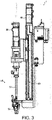
- FIG. 3 is a view illustrating an example of the appearance of the screw tightening system 1 according to the embodiment.
- the screw tightening system 1 includes the rotary servo 30, the reciprocal servo 40, a driver unit 50, and a strut 60.
- the screw tightening system 1 also includes the PLC 10 and the coupler 20 as described above.
- the driver unit 50 is a unit for tightening a screw.
- the driver unit 50 includes the driver 51 and a screw holder 52.
- the driver 51 executes a screw tightening operation through the rotary movement around the axis as well as the reciprocal movement in the axial direction.
- the movement direction of the driver 51 during the screw tightening process is referred to as "below/lower direction”.
- the rotary servo 30 is arranged above the driver 51 and generates the rotary movement of the driver 51 around the axis.
- the screw holder 52 holds a screw, which is provided below the driver 51 and is a target of screw tightening by the driver 51.
- the strut 60 supports the driver unit 50 to be movable in the upper-lower direction.
- the reciprocal servo 40 is provided at the upper part of the strut 60, and is connected to the driver unit 50 via a ball screw (not shown). The rotary movement of the reciprocal servo 40 is converted into a linear movement in the upper-lower direction by the ball screw. As a result, the driver unit 50 moves reciprocally in the upper-lower direction.
- the tightening operation by the screw tightening system 1 is as follows. Firstly, the screw holder 52 in the state of holding the screw is the target on which screw tightening is performed, and the screw holder 52 lowers the screw to a place where screw tightening is performed on the workpiece (not shown) formed by resin.
- the workpiece is not limited to resin, as long as it is formed by a soft material.
- the driver 51 presses against the screw while rotating the screw toward the place where screw tightening is performed until the screw is temporarily seated.
- being temporarily seated refers to a state in which the bearing surface of the screw is in contact with the workpiece.
- the screw tightening system 1 further performs final tightening by pressing while rotating the screw from the state in which the screw is temporarily seated.
- the final tightening is performed until the rotary torque of the rotary servo 30 reaches a predetermined final tightening completion value.
- the screw tightening system 1 stops pressing the screw and keeps the rotary torque in a state of being equal to or greater than the final tightening completion value for 100 ms.
- the screw tightening system 1 sets the rotary torque of the rotary servo 30 to be 0% or less and releases the screw. Moreover, the screw tightening system 1 completes the screw tightening operation by moving the driver 51 upward and restoring the driver 51 to the original position.
- the rotary torque and the holding time above merely serve as an example, and may differ in accordance with the type of the screw and the type of the tightening/tightened object.
- the determination unit 13 acquires the data points of the rotary torque from the coupler 20 via the communication unit 12. Then, among the acquired data points, the determination unit 13 generates a normalized torque data sequence for a rotary torque data sequence formed by data points of a predetermined number and ending with a data point at which the rotary torque is equal to or greater than a predetermined first threshold.
- the normalized torque data sequence refers to the amounts of change of the rotary torque in the respective data points with respect to the rotary torque at the initial data point of the rotary torque data sequence.
- the first threshold is a predetermined value for the rotary torque of the rotary servo 30 at the time when the temporary tightening of the screw tightening system 1 ends and the final tightening starts.
- the determination unit 13 acquires a second threshold from a storage device not shown herein.
- the second threshold refers to a predetermined threshold for determining that a screw tightening defect occurs and for the normalized torque value at the data point of a predetermined position among the normalized torque data sequence.
- the determination unit 13 determines that a screw tightening defect occurs in the case where the normalized torque at the data point of the predetermined position, among the normalized torque data sequence, is equal to or greater than a predetermined second threshold. Accordingly, the determination unit 13 can determine that a screw tightening defect occurs by determining that the normalized torque at the data point of the predetermined position, among the normalized torque data sequence, is equal to or greater than the second threshold.
- the determination unit 13 may also acquire a third threshold from the storage device not shown herein.
- the third threshold refers to a predetermined threshold for determining that a screw tightening defect occurs and for a total of normalized torques at the data points of a predetermined range among the normalized torque data sequence.
- the determination unit 13 determines that a screw tightening defect occurs in the case where the total of the normalized torques at the data points of the predetermined range, among the normalized torque data sequence, is equal to or greater than the third threshold. Accordingly, the determination unit 13 can determine that a screw tightening defect occurs by determining that the total of the normalized torques at the data points of the predetermined range, among the normalized torque data sequence, is equal to or greater than the third threshold.
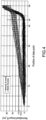
- FIG. 4 is a diagram illustrating a normalized torque data sequence according to the embodiment.
- the horizontal axis of FIG. 4 indicates the data point (sampling time), and the vertical axis thereof indicates the value of the normalized torque.
- Th2 in the vertical axis of FIG. 4 indicates the second threshold.
- the number of data points included in the normalized torque data sequence is set as 51, and the predetermined position is set at the 43 th position from the beginning of the data sequence. Therefore, in the case where the normalized torque at the 43 th data point is equal to or greater than Th2, the determination unit 13 determines that a screw tightening defect occurs.
- FIG. 4 the number of data points included in the normalized torque data sequence is set as 51, and the predetermined position is set at the 43 th position from the beginning of the data sequence. Therefore, in the case where the normalized torque at the 43 th data point is equal to or greater than Th2, the determination unit 13 determines that a screw tightening defect occurs.
- FIG. 4 the number of data points
- the data of the 50 screws where screw tightening is normal is shown in black, and the data of the 32 screws where screw tightening is abnormal is shown in gray.
- the normalized torques at the 43 th data points meet Th2.
- the normalized torques at the 43 th data points are all equal to or greater than Th2. Therefore, according to the above determination, the defects in screw tightening can be properly determined. It is noted that, for non-normalized torques (raw data) before the beginning point is matched, since the torque variation of each workpiece is large, it is not possible to separate a normal one from an abnormal one by using a single threshold.
- the specific value of the second threshold is properly set to a value able to determine normal and defective screw tightening.
- the number of the data points included in the normalized torque data sequence is set as appropriate without being limited to 51.
- the predetermined position is properly set at a position able to determine normal and defective screw tightening by using the second threshold without being limited to the 43 th position.
- the determination unit 13 makes a determination by using the third threshold, the same applies to the specific value of the third threshold as well as the specific range of the data points for calculating the total of the normalized torques.
- the screw tightening system 1 performs screw tightening with respect to the workpiece in a state of not having a female thread at the place where screw tightening is performed (tapping (self-tapping)).
- screw tightening with respect to the workpiece in the state (tapped) in which the female screw is provided in advance at the place where screw tightening is performed.
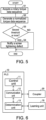
- FIG. 5 is a flowchart illustrating an example of a screw tightening defect determination process according to the embodiment. The determination on the occurrence of a defect in the screw tightening operation by the determination unit 13 is described with reference to FIG. 5 .
- the determination unit 13 acquires the rotary torque data sequence from the coupler 20 via the communication unit 12 (S1). Then, the determination unit 13 generates the normalized torque data sequence (S2). Then, the determination unit 13 acquires the second threshold from the storage device, and determines whether the normalized torque at the data point of the predetermined position, among the normalized torque data sequence, is equal to or greater than the second threshold (S3). In the case where the normalized torque is equal to or greater than the second threshold (YES in S3), the determination unit 13 outputs a notification signal indicating that the screw tightening is defective to the notification device (S4). In the case where the normalized torque is not equal to or greater than the second threshold (NO in S3), the determination unit 13 ends the process without executing Step S4.
- the determination unit 13 may also acquire the third threshold from the storage device in Step S3 and determines whether the total of the normalized torques at the data points of the predetermined range, among the normalized torque data sequence, is equal to or greater than the third threshold.
- the screw tightening system includes a learning unit 70 (learning device) in addition to the configuration of the screw tightening system 1.
- the learning unit 70 is configured to be able to perform machine learning, and is, for example, a personal computer, a smart phone, a portable information terminal, or a server.
- FIG. 6 is a block diagram illustrating a configuration of the PLC 10 and the learning device according to a modified example of the embodiment. As shown in FIG. 6 , in the modified example, the learning unit 70 is connected to the determination unit 13.
- the learning unit 70 makes a decision through learning one or more of the predetermined number, the predetermined position, and the second threshold in the PLC 10 based on learning data including the normalized torque data sequence and the determination result of being normal or defective for the normalized torque data sequence.
- the learning unit 70 may also make a decision through learning one or more of the predetermined number, the predetermined range, and the third threshold in the PLC 10 based on learning data including the normalized torque data sequence and the determination result of being normal or defective for the normalized torque data sequence.
- the learning unit 70 of the embodiment makes a decision through learning all of the predetermined number, the predetermined position, and the second threshold in the PLC 10 based on learning data including the normalized torque data sequence and the determination result of being normal or defective for the normalized torque data sequence.
- learning means machine learning and supervised learning.
- algorithm of supervised learning neural networks, isolation forests, or support vector machines are used, for example.
- the learning unit 70 may also calculate an abnormality score by using a probability density function and a kernelized stochastic model.
- the probability density function may be a normal distribution, for example.
- the invention is not limited thereto.
- the learning unit 70 outputs the predetermined number, the predetermined position, or the second threshold that is determined to the determination unit 13 provided in the PLC 10. Accordingly, based on the predetermined number, the predetermined position, or the second threshold that is determined, the determination unit 13 can determine that a screw tightening defect occurs. However, the learning unit 70 may also output the predetermined number, the predetermined range, or the third threshold that is determined to the determination unit 13 provided in the PLC 10. The learning unit 70 of the embodiment outputs the predetermined number, the predetermined position, and the second threshold that are determined to the determination unit 13 provided in the PLC 10. Accordingly, based on the determined predetermined number, predetermined position, and second threshold that are learned by the learning unit 70, the determination unit 13 can determine that a screw tightening defect occurs. In the case where the learning unit 70 does not determine, through learning, one or more of the predetermined number, the predetermined position, and the second threshold, values that are not determined may also be stored in advance in the storage device.
- the learning unit 70 updates, through learning, one or more of the predetermined number, the predetermined position, and the second threshold based on the normalized torque data sequence in the screw tightening and the result of determination made by the determination unit. Accordingly, based on the predetermined number, the predetermined position, or the second threshold that is updated, the determination unit 13 can determine that a screw tightening defect occurs.
- the learning unit 70 may also update, through learning, one or more of the predetermined number, the predetermined range, and the third threshold based on the normalized torque data sequence in the screw tightening and the result of determination made by the determination unit.
- the learning unit 70 in the embodiment updates, through learning, all of the predetermined number, the predetermined position, and the second threshold based on the normalized torque data sequence in screw tightening and the result of determination by the determination unit. Accordingly, based on the predetermined number, the predetermined position, and the second threshold that are updated, the determination unit 13 can determine that a screw tightening defect occurs.
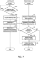
- FIG. 7 is a flowchart illustrating an example of a screw tightening defect determination process according to a modified example. The determination on the occurrence of a defect in the screw tightening operation by the determination unit 13 and the learning unit 70 is described with reference to FIG. 7 .
- the determination unit 13 performs the processes from S1 to S5. Since the processes performed by the determination unit 13 from S1 to S4 are the same as the above, the description thereof will be omitted.
- the determination unit 13 outputs the data of the determination result to the learning unit 70 (S5). Specifically, the determination unit 13 outputs the learning data including the normalized torque data sequence and the determination result of being normal or defective for the normalized torque data sequence to the learning unit 70. Then, the determination unit 13 ends the process of determining the occurrence of a defect.
- the learning unit 70 determines that the learning start condition is satisfied (S11).
- the learning start condition includes, for example:
- the learning unit 70 determines that the learning start condition is satisfied.
- the learning start condition is not limited to the above. In addition, it may suffice if one or more of these conditions do not serve as the learning start condition.
- the learning unit 70 repeats Step S11 until the learning start condition is satisfied.
- the learning unit 70 acquires the learning data (S12).
- the learning data is teacher data stored in the storage device.
- the learning data is the learning data stored into the storage device from the determination unit 13 in Step S5. Then, the learning unit 70 determines, through learning, the predetermined number in the PLC 10 based on the learning data, and outputs the predetermined number to the determination unit 13 (S13).
- the determination unit 13 determines, through learning, the predetermined position and the second threshold in the PLC 10 based on the learning data, and outputs the predetermined position and the second threshold to the determination unit 13 (S14). Then, the learning unit 70 ends the learning process.
- the determination unit 13 may also determine, through learning, the predetermined range and the third threshold in the PLC 10 based on the learning data in S 14, and output the predetermined range and the third threshold to the determination unit 13.
- the control block (in particular, the determination unit 13) of the PLC 10 and the learning unit 70 may be realized by logic circuits (hardware) formed in integrated circuits (IC chips), and may also be realized as software.
- the PLC 10 includes a computer for executing commands of a program that is the software for realizing the respective functions.
- the computer for example, includes one or more processors, and includes a computer-readable recording medium storing the program.
- the processor reads the program from the recording medium and executing the program. Accordingly, the objective of the invention is achieved.
- a central processing unit (CPU), for example, can be used as the processor.
- the recording medium a "non-transitory tangible medium", such as a read only memory (ROM), a tape, a disc, a card, a semiconductor memory, a programmable logic circuit can be used.
- a random access memory (RAM) for expanding the program may be further provided.
- the program may also be supplied to the computer via any transmission medium (a communication network, broadcasting waves, etc.) able to transmit the program.
- the program may also be realized in the form of data signals embodied through electronic transmission and embedded in carrier waves.
- an aspect of the invention provides a screw tightening defect determination device which, among data points sampling, at a predetermined cycle, a rotary torque of a motor that generates a rotary movement of a driver for tightening a screw and around an axis, generates a normalized torque data sequence that is an amount of change with respect to the rotary torque at an initial data point of a data sequence for the data sequence, the data sequence being a data sequence of the rotary torque formed by data points of a predetermined number and ending with a data point at which the rotary torque is equal to or greater than a predetermined first threshold, and determines whether a defect occurs in screw tightening based on the normalized torque data sequence.
- the normalized torque data sequence is compared with, for example, a torque data sequence at the time of abnormality, and whether a defect occurs in screw tightening can be determined. Therefore, in the case where a tapping screw is used in a soft material, for example, even if the torque value changes for each workpiece, whether a defect occurs in screw tightening can be determined.
- the determination unit determines that a defect occurs in the screw tightening.
- the occurrence of a screw tightening defect can be determined by determining that the normalized torque at the data point of the predetermined position, among the normalized torque data sequence, is equal to or greater than the second threshold.
- an aspect of the invention provides a learning device determining, through learning, one or more of the predetermined number, the predetermined position, and the predetermined second threshold in the screw tightening defect determination device based on learning data including the normalized torque data sequence and a result of determination of being normal or defective for the normalized torque data sequence, and outputting the predetermined number, the predetermined position, or the predetermined second threshold that is determined to the screw tightening defect determination device.
- the occurrence of a screw tightening defect can be properly determined.
- the learning device may also be that, in a case where there is a predetermined number of times of determination by the determination unit, a predetermined lapsed period, or an instruction from outside, the learning device updates, through learning, one or more of the predetermined number, the predetermined position, and the predetermined second threshold based on the normalized torque data sequence in the screw tightening and the result of determination made by the determination unit.
- the occurrence of a screw tightening defect can be properly determined.
- the determination unit determines that a defect occurs in the screw tightening.
- the occurrence of a screw tightening defect can be determined by determining that the total of the normalized torques at the data points of the predetermined range, among the normalized torque data sequence, is equal to or greater than the third threshold.
- an aspect of the invention provides a learning device determining, through learning, one or more of the predetermined number, the predetermined range, and the predetermined third threshold in the screw tightening defect determination device based on learning data including the normalized torque data sequence and a result of determination of being normal or defective for the normalized torque data sequence, and outputting the predetermined number, the predetermined range, or the predetermined third threshold that is determined to the screw tightening defect determination device.
- the occurrence of a screw tightening defect can be properly determined.
- the learning device may also be that, in a case where there is a predetermined number of times of determination by the determination unit, a predetermined lapsed period, or an instruction from outside, the learning device updates, through learning, one or more of the predetermined number, the predetermined range, and the predetermined third threshold based on the normalized torque data sequence in the screw tightening and the result of determination made by the determination unit.
- the occurrence of a screw tightening defect can be properly determined.
Landscapes
- Engineering & Computer Science (AREA)
- Mechanical Engineering (AREA)
- Physics & Mathematics (AREA)
- General Physics & Mathematics (AREA)
- Automation & Control Theory (AREA)
- Details Of Spanners, Wrenches, And Screw Drivers And Accessories (AREA)
- Testing Of Devices, Machine Parts, Or Other Structures Thereof (AREA)
Abstract
Description
- The invention relates to a screw tightening defect determination device.
-
Patent Literature 1 discloses a screw tightening state detection device of an electric rotary tool, including a cylindrical casing accommodating a spring elastically supporting a steel ball engaged with an internal gear of a deceleration mechanism in a clutch mechanism, provided with a torque adjustment mechanism having an externally operable adjustment screw performing elastic adjustment of the spring inside the cylindrical casing, and provided with a torque detection element on an outer surface of the cylindrical casing. - The screw tightening state detection device of the electric rotary tool recited in
Patent Literature 1 is capable of determining whether the screw tightening state is favorable or defective by converting a detection value of the output signal detected by the torque detection element at the time of a screw tightening process, for example, into a torque value based on the detection value. - [Patent Literature 1]
Japanese Laid-open No. 2016-147317 - However, for example, in the case where a tapping screw is used with respect to a soft material (workpiece), such as resin, due to an incorrect screw length or defective formation of the workpiece, a phenomenon may occur that the tip of the tapping screw advances over the bottom part of the workpiece during temporary tightening, which is a process performed until the bearing surface of the tapping screw contacts the workpiece. In such case, the torque value required until final tightening, which is a process after the bearing surface of the tapping screw contacts the workpiece from the temporary screwing of the tapping screw, for example, is different. However, the torque value varies for each workpiece. Therefore, it is difficult to determine whether the tapping screw normally arrives at the bottom by simply performing determination on whether the screw tightening state is favorable or defective based solely on the torque value in the screw tightening state detection device of the electric rotary tool described in
- An objective of an aspect of the invention is to realize a screw tightening defect determination device capable of determining whether a screw tightening defect occurs even in the case where a tapping screw is used in a soft material.
- In order to solve the above issue, an aspect of the invention provides a screw tightening defect determination device, which, among data points sampling, at a predetermined cycle, a rotary torque of a motor that generates a rotary movement of a driver for tightening a screw and around an axis, generates a normalized torque data sequence that is an amount of change with respect to the rotary torque at an initial data point of a data sequence for the data sequence, the data sequence being a data sequence of the rotary torque formed by data points of a predetermined number and ending with a data point at which the rotary torque is equal to or greater than a predetermined first threshold, and determines whether a defect occurs in screw tightening based on the normalized torque data sequence.
- According to the screw tightening defect determination device according to an aspect of the invention, whether a defect occurs in screw tightening can be determined even in the case where a tapping screw is used in a soft material.
-
-
FIG. 1 is a block diagram schematically illustrating a screw tightening system according to an embodiment. -
FIG. 2 is a block diagram illustrating a configuration of a PLC according to the embodiment. -
FIG. 3 is a view illustrating an example of the appearance of the screw tightening system according to the embodiment. -
FIG. 4 is a diagram illustrating a normalized torque data sequence according to the embodiment. -
FIG. 5 is a flowchart illustrating an example of a screw tightening defect determination process according to the embodiment. -
FIG. 6 is a block diagram illustrating a configuration of a PLC and a learning device according to a modified example of the embodiment. -
FIG. 7 is a flowchart illustrating an example of a screw tightening defect determination process according to a modified example of the embodiment. - In the following, an embodiment (referred to as "the embodiment" in the following) according to an aspect of the invention is described based on the drawings.
-
FIG. 1 is a block diagram schematically illustrating ascrew tightening system 1 according to an embodiment. As shown inFIG. 1 , thescrew tightening system 1 includes a programmable logic controller 10 (screw tightening defect determination device), acoupler 20, a rotary servo 30 (first motor), and a reciprocal servo 40 (second motor). Thescrew tightening system 1 performs a screw tightening operation through a rotary movement of a driver 51 (seeFIG. 3 ), which will be described afterwards, around an axis and a reciprocal movement of thedriver 51 toward an axial direction. At this time, thePLC 10 exerts control on the screw tightening operation and determines whether a defect occurs in the screw tightening operation. - In the specification, the defect in the screw tightening operation means bottoming. Bottoming means the screw reaches the bottom of the screw hole before screw tightening is completed because the screw is longer than the screw hole or the workpiece is not properly formed.
- The
rotary servo 30 is a motor that generates a rotary movement of thedriver 51 around the axis. In addition, therotary servo 30 outputs its own rotary velocity (deg./s), rotary amount (deg.), and rotary torque (proportion (%) with respect to a rated torque) to thecoupler 20. Specifically, therotary servo 30 outputs data points sampling its own rotary velocity, rotary amount, and rotary torque at a predetermined cycle to thecoupler 20. - The
reciprocal servo 40 is a motor generating a reciprocal movement in the axial direction of thedriver 51. In addition, therotary servo 40 outputs the movement velocity (mm/s), movement position (mm), and movement torque (proportion (%) with respect to a rated torque) of thedriver 51 due to its own rotation to thecoupler 20. - The
coupler 20 is connected to thePLC 10, therotary servo 30, and thereciprocal servo 40. Specifically, thecoupler 20 transmits a control signal received from thePLC 10 to therotary servo 30 and thereciprocal servo 40. In addition, thecoupler 20 transmits the data points sampling the rotary velocity, the rotary amount, and the rotary torque of therotary servo 30 at a predetermined cycle that are received from therotary servo 30 to thePLC 10. In addition, thecoupler 20 transmits the movement velocity, the movement position, and the movement torque of thedriver 51 due to the rotation of thereciprocal servo 40 that are received from thereciprocal servo 40 to thePLC 10. - In the following description, the rotary velocity, the rotary amount, and the rotary torque of the
rotary servo 30 and the movement velocity, the movement position, and the movement torque of thedriver 51 due to the rotation of thereciprocal servo 40 arranged in the data sequence of the rotary torque are generally referred to as parameters. -
FIG. 2 is a block diagram illustrating a configuration of thePLC 10. ThePLC 10 controls the operation of thescrew tightening system 1. As shown inFIG. 2 , thePLC 10 includes acontroller 11, acommunication unit 12, and adetermination unit 13. - The
controller 11 outputs a control signal for controlling therotary servo 30 and thereciprocal servo 40 to thecommunication unit 12. Thecommunication unit 12 transmits the control signal input from thecontroller 11 to thecoupler 20. The control signal is transmitted to therotary servo 30 and thereciprocal servo 40 via thecoupler 20, and controls therotary servo 30 and thereciprocal servo 40. Thecontroller 11 synchronizes and controls therotary servo 30 and thereciprocal servo 40. In addition, thecontroller 11 feeds the parameters of therotary servo 30 and thereciprocal servo 40 back to the control of therotary servo 30 and thereciprocal servo 40. - The
communication unit 12 receives the parameters from therotary servo 30 and thereciprocal servo 40 via thecoupler 20. Thecontrol unit 11 and thedetermination unit 13 acquire the parameters as necessary from thecoupler 20 via thecommunication unit 12. - The
determination unit 13 determines whether a screw tightening defect occurs. The content of the determination made by thedetermination unit 13 will be described in the following. - In addition, the
screw tightening system 1 includes a notification device not shown herein. In the case of determining that a screw tightening defect occurs, thedetermination unit 13 outputs the determination result through the notification device. The notification device is a speaker which outputs a sound indicating the determination result or a display displaying an image indicating the determination result, for example. -
FIG. 3 is a view illustrating an example of the appearance of thescrew tightening system 1 according to the embodiment. As shown inFIG. 3 , thescrew tightening system 1 includes therotary servo 30, thereciprocal servo 40, adriver unit 50, and astrut 60. In addition, while not shown inFIG. 3 , thescrew tightening system 1 also includes thePLC 10 and thecoupler 20 as described above. - The
driver unit 50 is a unit for tightening a screw. Thedriver unit 50 includes thedriver 51 and ascrew holder 52. Thedriver 51 executes a screw tightening operation through the rotary movement around the axis as well as the reciprocal movement in the axial direction. In the following, in the axial direction of thedriver 51, the movement direction of thedriver 51 during the screw tightening process is referred to as "below/lower direction". - The
rotary servo 30 is arranged above thedriver 51 and generates the rotary movement of thedriver 51 around the axis. In addition, thescrew holder 52 holds a screw, which is provided below thedriver 51 and is a target of screw tightening by thedriver 51. - The
strut 60 supports thedriver unit 50 to be movable in the upper-lower direction. Thereciprocal servo 40 is provided at the upper part of thestrut 60, and is connected to thedriver unit 50 via a ball screw (not shown). The rotary movement of thereciprocal servo 40 is converted into a linear movement in the upper-lower direction by the ball screw. As a result, thedriver unit 50 moves reciprocally in the upper-lower direction. - The tightening operation by the
screw tightening system 1 is as follows. Firstly, thescrew holder 52 in the state of holding the screw is the target on which screw tightening is performed, and thescrew holder 52 lowers the screw to a place where screw tightening is performed on the workpiece (not shown) formed by resin. However, the workpiece is not limited to resin, as long as it is formed by a soft material. Then, thedriver 51 presses against the screw while rotating the screw toward the place where screw tightening is performed until the screw is temporarily seated. Here, being temporarily seated refers to a state in which the bearing surface of the screw is in contact with the workpiece. - The
screw tightening system 1 further performs final tightening by pressing while rotating the screw from the state in which the screw is temporarily seated. In the embodiment, the final tightening is performed until the rotary torque of therotary servo 30 reaches a predetermined final tightening completion value. When the rotary torque reaches the final tightening completion value, thescrew tightening system 1 stops pressing the screw and keeps the rotary torque in a state of being equal to or greater than the final tightening completion value for 100 ms. - Then, the
screw tightening system 1 sets the rotary torque of therotary servo 30 to be 0% or less and releases the screw. Moreover, thescrew tightening system 1 completes the screw tightening operation by moving thedriver 51 upward and restoring thedriver 51 to the original position. However, the rotary torque and the holding time above merely serve as an example, and may differ in accordance with the type of the screw and the type of the tightening/tightened object. - Specifically, the
determination unit 13 acquires the data points of the rotary torque from thecoupler 20 via thecommunication unit 12. Then, among the acquired data points, thedetermination unit 13 generates a normalized torque data sequence for a rotary torque data sequence formed by data points of a predetermined number and ending with a data point at which the rotary torque is equal to or greater than a predetermined first threshold. Here, the normalized torque data sequence refers to the amounts of change of the rotary torque in the respective data points with respect to the rotary torque at the initial data point of the rotary torque data sequence. In addition, the first threshold is a predetermined value for the rotary torque of therotary servo 30 at the time when the temporary tightening of thescrew tightening system 1 ends and the final tightening starts. - The
determination unit 13 acquires a second threshold from a storage device not shown herein. Here, the second threshold refers to a predetermined threshold for determining that a screw tightening defect occurs and for the normalized torque value at the data point of a predetermined position among the normalized torque data sequence. - The
determination unit 13 determines that a screw tightening defect occurs in the case where the normalized torque at the data point of the predetermined position, among the normalized torque data sequence, is equal to or greater than a predetermined second threshold. Accordingly, thedetermination unit 13 can determine that a screw tightening defect occurs by determining that the normalized torque at the data point of the predetermined position, among the normalized torque data sequence, is equal to or greater than the second threshold. - It is noted that the
determination unit 13 may also acquire a third threshold from the storage device not shown herein. Here, the third threshold refers to a predetermined threshold for determining that a screw tightening defect occurs and for a total of normalized torques at the data points of a predetermined range among the normalized torque data sequence. - In this case, the
determination unit 13 determines that a screw tightening defect occurs in the case where the total of the normalized torques at the data points of the predetermined range, among the normalized torque data sequence, is equal to or greater than the third threshold. Accordingly, thedetermination unit 13 can determine that a screw tightening defect occurs by determining that the total of the normalized torques at the data points of the predetermined range, among the normalized torque data sequence, is equal to or greater than the third threshold. -
FIG. 4 is a diagram illustrating a normalized torque data sequence according to the embodiment. The horizontal axis ofFIG. 4 indicates the data point (sampling time), and the vertical axis thereof indicates the value of the normalized torque. Th2 in the vertical axis ofFIG. 4 indicates the second threshold. In the example shown inFIG. 4 , the number of data points included in the normalized torque data sequence is set as 51, and the predetermined position is set at the 43th position from the beginning of the data sequence. Therefore, in the case where the normalized torque at the 43th data point is equal to or greater than Th2, thedetermination unit 13 determines that a screw tightening defect occurs. InFIG. 4 , the data of the 50 screws where screw tightening is normal is shown in black, and the data of the 32 screws where screw tightening is abnormal is shown in gray. In the data of the screws that are normal, neither of the normalized torques at the 43th data points meets Th2. Meanwhile, in the data of the screws that are abnormal, since the torque increases because the screws advance over the bottom of the screw holes, the normalized torques at the 43th data points are all equal to or greater than Th2. Therefore, according to the above determination, the defects in screw tightening can be properly determined. It is noted that, for non-normalized torques (raw data) before the beginning point is matched, since the torque variation of each workpiece is large, it is not possible to separate a normal one from an abnormal one by using a single threshold. - It suffices that the specific value of the second threshold is properly set to a value able to determine normal and defective screw tightening. In addition, it suffices that the number of the data points included in the normalized torque data sequence is set as appropriate without being limited to 51. In addition, it suffices that the predetermined position is properly set at a position able to determine normal and defective screw tightening by using the second threshold without being limited to the 43th position. In addition, in the case where the
determination unit 13 makes a determination by using the third threshold, the same applies to the specific value of the third threshold as well as the specific range of the data points for calculating the total of the normalized torques. - It is noted that, in the above example of the screw tightening operation, the
screw tightening system 1 performs screw tightening with respect to the workpiece in a state of not having a female thread at the place where screw tightening is performed (tapping (self-tapping)). However, it is possible to perform screw tightening with respect to the workpiece in the state (tapped) in which the female screw is provided in advance at the place where screw tightening is performed. -
FIG. 5 is a flowchart illustrating an example of a screw tightening defect determination process according to the embodiment. The determination on the occurrence of a defect in the screw tightening operation by thedetermination unit 13 is described with reference toFIG. 5 . - As shown in
FIG. 5 , thedetermination unit 13 acquires the rotary torque data sequence from thecoupler 20 via the communication unit 12 (S1). Then, thedetermination unit 13 generates the normalized torque data sequence (S2). Then, thedetermination unit 13 acquires the second threshold from the storage device, and determines whether the normalized torque at the data point of the predetermined position, among the normalized torque data sequence, is equal to or greater than the second threshold (S3). In the case where the normalized torque is equal to or greater than the second threshold (YES in S3), thedetermination unit 13 outputs a notification signal indicating that the screw tightening is defective to the notification device (S4). In the case where the normalized torque is not equal to or greater than the second threshold (NO in S3), thedetermination unit 13 ends the process without executing Step S4. - It is noted that the
determination unit 13 may also acquire the third threshold from the storage device in Step S3 and determines whether the total of the normalized torques at the data points of the predetermined range, among the normalized torque data sequence, is equal to or greater than the third threshold. - Although the configuration of the embodiment of the invention has been described in detail, the foregoing description is merely an illustrative example in all aspects. It goes without saying that various modifications and variations can be made without departing from the scope of the invention. For example, it is possible to make changes as follows. In the following, the same reference symbols are used for components same as the above embodiment, and the appropriate descriptions for points same as the above embodiment are omitted. It is possible to properly combine the modified examples as follows.
- The screw tightening system according to the modified example includes a learning unit 70 (learning device) in addition to the configuration of the
screw tightening system 1. Thelearning unit 70 is configured to be able to perform machine learning, and is, for example, a personal computer, a smart phone, a portable information terminal, or a server. -
FIG. 6 is a block diagram illustrating a configuration of thePLC 10 and the learning device according to a modified example of the embodiment. As shown inFIG. 6 , in the modified example, thelearning unit 70 is connected to thedetermination unit 13. - The
learning unit 70 makes a decision through learning one or more of the predetermined number, the predetermined position, and the second threshold in thePLC 10 based on learning data including the normalized torque data sequence and the determination result of being normal or defective for the normalized torque data sequence. However, thelearning unit 70 may also make a decision through learning one or more of the predetermined number, the predetermined range, and the third threshold in thePLC 10 based on learning data including the normalized torque data sequence and the determination result of being normal or defective for the normalized torque data sequence. Thelearning unit 70 of the embodiment makes a decision through learning all of the predetermined number, the predetermined position, and the second threshold in thePLC 10 based on learning data including the normalized torque data sequence and the determination result of being normal or defective for the normalized torque data sequence. - Here, learning means machine learning and supervised learning. As the algorithm of supervised learning, neural networks, isolation forests, or support vector machines are used, for example. In addition, the
learning unit 70 may also calculate an abnormality score by using a probability density function and a kernelized stochastic model. The probability density function may be a normal distribution, for example. However, the invention is not limited thereto. - The
learning unit 70 outputs the predetermined number, the predetermined position, or the second threshold that is determined to thedetermination unit 13 provided in thePLC 10. Accordingly, based on the predetermined number, the predetermined position, or the second threshold that is determined, thedetermination unit 13 can determine that a screw tightening defect occurs. However, thelearning unit 70 may also output the predetermined number, the predetermined range, or the third threshold that is determined to thedetermination unit 13 provided in thePLC 10. Thelearning unit 70 of the embodiment outputs the predetermined number, the predetermined position, and the second threshold that are determined to thedetermination unit 13 provided in thePLC 10. Accordingly, based on the determined predetermined number, predetermined position, and second threshold that are learned by thelearning unit 70, thedetermination unit 13 can determine that a screw tightening defect occurs. In the case where thelearning unit 70 does not determine, through learning, one or more of the predetermined number, the predetermined position, and the second threshold, values that are not determined may also be stored in advance in the storage device. - In the case where there is a predetermined number of times of determination by the
determination unit 13, a predetermined lapsed period, or an instruction from the outside, thelearning unit 70 updates, through learning, one or more of the predetermined number, the predetermined position, and the second threshold based on the normalized torque data sequence in the screw tightening and the result of determination made by the determination unit. Accordingly, based on the predetermined number, the predetermined position, or the second threshold that is updated, thedetermination unit 13 can determine that a screw tightening defect occurs. However, in the case where there is a determination on the predetermined number of times of determination by thedetermination unit 13, a predetermined lapsed period, or an instruction from the outside, thelearning unit 70 may also update, through learning, one or more of the predetermined number, the predetermined range, and the third threshold based on the normalized torque data sequence in the screw tightening and the result of determination made by the determination unit. In the case where a learning start condition is satisfied, thelearning unit 70 in the embodiment updates, through learning, all of the predetermined number, the predetermined position, and the second threshold based on the normalized torque data sequence in screw tightening and the result of determination by the determination unit. Accordingly, based on the predetermined number, the predetermined position, and the second threshold that are updated, thedetermination unit 13 can determine that a screw tightening defect occurs. -
FIG. 7 is a flowchart illustrating an example of a screw tightening defect determination process according to a modified example. The determination on the occurrence of a defect in the screw tightening operation by thedetermination unit 13 and thelearning unit 70 is described with reference toFIG. 7 . As shown inFIG. 7 , thedetermination unit 13 performs the processes from S1 to S5. Since the processes performed by thedetermination unit 13 from S1 to S4 are the same as the above, the description thereof will be omitted. In the case where the normalized torque is not equal to or greater than the second threshold (NO in S3), or after a notification signal indicating that the screw tightening is defective is output to the notification device (S4), thedetermination unit 13 outputs the data of the determination result to the learning unit 70 (S5). Specifically, thedetermination unit 13 outputs the learning data including the normalized torque data sequence and the determination result of being normal or defective for the normalized torque data sequence to thelearning unit 70. Then, thedetermination unit 13 ends the process of determining the occurrence of a defect. - The
learning unit 70 determines that the learning start condition is satisfied (S11). The learning start condition includes, for example: - (i) immediately after the process of the
learning unit 70 starts; - (ii) the
determination unit 13 performs determination for a predetermined number of times; - (iii) a predetermined period has passed since the last time when the learning start condition is satisfied; and
- (iv) receiving a learning start instruction from the outside.
- In the case where any of these conditions is satisfied, the
learning unit 70 determines that the learning start condition is satisfied. However, the learning start condition is not limited to the above. In addition, it may suffice if one or more of these conditions do not serve as the learning start condition. - In the case where the learning start condition is not satisfied ("NO" in S11), the
learning unit 70 repeats Step S11 until the learning start condition is satisfied. In the case where the learning start condition is satisfied ("YES" in S11), thelearning unit 70 acquires the learning data (S12). In the case immediately after the process of thelearning unit 70 starts, the learning data is teacher data stored in the storage device. In other cases, the learning data is the learning data stored into the storage device from thedetermination unit 13 in Step S5. Then, thelearning unit 70 determines, through learning, the predetermined number in thePLC 10 based on the learning data, and outputs the predetermined number to the determination unit 13 (S13). Then, thedetermination unit 13 determines, through learning, the predetermined position and the second threshold in thePLC 10 based on the learning data, and outputs the predetermined position and the second threshold to the determination unit 13 (S14). Then, thelearning unit 70 ends the learning process. - In the case where the
determination unit 13 makes a determination by using the third threshold as the reference in S3, thedetermination unit 13 may also determine, through learning, the predetermined range and the third threshold in thePLC 10 based on the learning data inS 14, and output the predetermined range and the third threshold to thedetermination unit 13. - The control block (in particular, the determination unit 13) of the
PLC 10 and thelearning unit 70 may be realized by logic circuits (hardware) formed in integrated circuits (IC chips), and may also be realized as software. - In the latter case, the
PLC 10 includes a computer for executing commands of a program that is the software for realizing the respective functions. The computer, for example, includes one or more processors, and includes a computer-readable recording medium storing the program. Moreover, in the computer, the processor reads the program from the recording medium and executing the program. Accordingly, the objective of the invention is achieved. A central processing unit (CPU), for example, can be used as the processor. As the recording medium, a "non-transitory tangible medium", such as a read only memory (ROM), a tape, a disc, a card, a semiconductor memory, a programmable logic circuit can be used. In addition, a random access memory (RAM) for expanding the program may be further provided. In addition, the program may also be supplied to the computer via any transmission medium (a communication network, broadcasting waves, etc.) able to transmit the program. In an aspect of the invention, the program may also be realized in the form of data signals embodied through electronic transmission and embedded in carrier waves. - In order to solve the above issue, an aspect of the invention provides a screw tightening defect determination device which, among data points sampling, at a predetermined cycle, a rotary torque of a motor that generates a rotary movement of a driver for tightening a screw and around an axis, generates a normalized torque data sequence that is an amount of change with respect to the rotary torque at an initial data point of a data sequence for the data sequence, the data sequence being a data sequence of the rotary torque formed by data points of a predetermined number and ending with a data point at which the rotary torque is equal to or greater than a predetermined first threshold, and determines whether a defect occurs in screw tightening based on the normalized torque data sequence.
- According to the above configuration, the normalized torque data sequence is compared with, for example, a torque data sequence at the time of abnormality, and whether a defect occurs in screw tightening can be determined. Therefore, in the case where a tapping screw is used in a soft material, for example, even if the torque value changes for each workpiece, whether a defect occurs in screw tightening can be determined.
- In addition, in the screw tightening defect determination device according to an aspect of the invention, it may also be that, in a case where a normalized torque in a data point of a predetermined position, among the normalized torque data sequence, is equal to or greater than a predetermined second threshold, the determination unit determines that a defect occurs in the screw tightening.
- According to the configuration, the occurrence of a screw tightening defect can be determined by determining that the normalized torque at the data point of the predetermined position, among the normalized torque data sequence, is equal to or greater than the second threshold.
- In addition, an aspect of the invention provides a learning device determining, through learning, one or more of the predetermined number, the predetermined position, and the predetermined second threshold in the screw tightening defect determination device based on learning data including the normalized torque data sequence and a result of determination of being normal or defective for the normalized torque data sequence, and outputting the predetermined number, the predetermined position, or the predetermined second threshold that is determined to the screw tightening defect determination device.
- According to the configuration, based on the predetermined number, the predetermined position, or the second threshold that is determined through learning, the occurrence of a screw tightening defect can be properly determined.
- Regarding the learning device according to an aspect of the invention, it may also be that, in a case where there is a predetermined number of times of determination by the determination unit, a predetermined lapsed period, or an instruction from outside, the learning device updates, through learning, one or more of the predetermined number, the predetermined position, and the predetermined second threshold based on the normalized torque data sequence in the screw tightening and the result of determination made by the determination unit.
- According to the configuration, based on the predetermined number, the predetermined position, or the second threshold that is updated, the occurrence of a screw tightening defect can be properly determined.
- In addition, in the screw tightening defect determination device according to an aspect of the invention, it may also be that, in a case where a total of normalized torques in data points of a predetermined range, among the normalized torque data sequence, is equal to or greater than a predetermined third threshold, the determination unit determines that a defect occurs in the screw tightening.
- According to the configuration, the occurrence of a screw tightening defect can be determined by determining that the total of the normalized torques at the data points of the predetermined range, among the normalized torque data sequence, is equal to or greater than the third threshold.
- In addition, an aspect of the invention provides a learning device determining, through learning, one or more of the predetermined number, the predetermined range, and the predetermined third threshold in the screw tightening defect determination device based on learning data including the normalized torque data sequence and a result of determination of being normal or defective for the normalized torque data sequence, and outputting the predetermined number, the predetermined range, or the predetermined third threshold that is determined to the screw tightening defect determination device.
- According to the configuration, based on the predetermined number, the predetermined range, or the third threshold that is determined through learning, the occurrence of a screw tightening defect can be properly determined.
- Regarding the learning device according to an aspect of the invention, it may also be that, in a case where there is a predetermined number of times of determination by the determination unit, a predetermined lapsed period, or an instruction from outside, the learning device updates, through learning, one or more of the predetermined number, the predetermined range, and the predetermined third threshold based on the normalized torque data sequence in the screw tightening and the result of determination made by the determination unit.
- According to the configuration, based on the predetermined number, the predetermined range, or the third threshold that is updated, the occurrence of a screw tightening defect can be properly determined.
- The invention is not limited to the above-described embodiments, and various modifications are possible within the scope indicated in the claims. Embodiments obtained by appropriately combining technical means disclosed in different embodiments are also included in the technical scope of the invention.
-
- 1: Screw tightening system;
- 10: PLC (screw tightening defect determination device);
- 30: Rotary servo (first motor);
- 40: Reciprocal servo (second motor);
- 51: Driver;
- 70: Learning unit (learning device).
Claims (7)
- A screw tightening defect determination device, comprising: a determination unit which, among data points sampling, at a predetermined cycle, a rotary torque of a motor that generates a rotary movement of a driver for tightening a screw and around an axis, generates a normalized torque data sequence that is an amount of change with respect to the rotary torque at an initial data point of a data sequence for the data sequence, the data sequence being a data sequence of the rotary torque formed by data points of a predetermined number and ending with a data point at which the rotary torque is equal to or greater than a predetermined first threshold, and
the determination unit determines whether a defect occurs in screw tightening based on the normalized torque data sequence. - The screw tightening defect determination device as claimed in claim 1, wherein in a case where a normalized torque in a data point of a predetermined position, among the normalized torque data sequence, is equal to or greater than a predetermined second threshold, the determination unit determines that a defect occurs in the screw tightening.
- A learning device, determining, through learning, one or more of the predetermined number, the predetermined position, and the predetermined second threshold in the screw tightening defect determination device as claimed in claim 2 based on learning data comprising the normalized torque data sequence and a result of determination of being normal or defective for the normalized torque data sequence; and
outputting the predetermined number, the predetermined position, or the predetermined second threshold that is determined to the screw tightening defect determination device. - The learning device as claimed in claim 3, wherein in a case where there is a predetermined number of times of determination by the determination unit, a predetermined lapsed period, or an instruction from outside, the learning device updates, through learning, one or more of the predetermined number, the predetermined position, and the predetermined second threshold based on the normalized torque data sequence in the screw tightening and the result of determination made by the determination unit.
- The screw tightening defect determination device as claimed in claim 1, wherein in a case where a total of normalized torques in data points of a predetermined range, among the normalized torque data sequence, is equal to or greater than a predetermined third threshold, the determination unit determines that a defect occurs in the screw tightening.
- A learning device, determining, through learning, one or more of the predetermined number, the predetermined range, and the predetermined third threshold in the screw tightening defect determination device as claimed in claim 5 based on learning data comprising the normalized torque data sequence and a result of determination of being normal or defective for the normalized torque data sequence; and
outputting the predetermined number, the predetermined range, or the predetermined third threshold that is determined to the screw tightening defect determination device. - The learning device as claimed in claim 6, wherein in a case where there is a predetermined number of times of determination by the determination unit, a predetermined lapsed period, or an instruction from outside, the learning device updates, through learning, one or more of the predetermined number, the predetermined range, and the predetermined third threshold based on the normalized torque data sequence in the screw tightening and the result of determination made by the determination unit.
Applications Claiming Priority (2)
| Application Number | Priority Date | Filing Date | Title |
|---|---|---|---|
| JP2020088129A JP7600542B2 (en) | 2020-05-20 | 2020-05-20 | Screw tightening defect detection device |
| PCT/JP2021/007993 WO2021235041A1 (en) | 2020-05-20 | 2021-03-02 | Screw tightening defect determination device |
Publications (2)
| Publication Number | Publication Date |
|---|---|
| EP4155028A1 true EP4155028A1 (en) | 2023-03-29 |
| EP4155028A4 EP4155028A4 (en) | 2025-01-08 |
Family
ID=78605889
Family Applications (1)
| Application Number | Title | Priority Date | Filing Date |
|---|---|---|---|
| EP21808738.5A Withdrawn EP4155028A4 (en) | 2020-05-20 | 2021-03-02 | SCREWING DEFECT DETERMINATION DEVICE |
Country Status (5)
| Country | Link |
|---|---|
| US (1) | US12220777B2 (en) |
| EP (1) | EP4155028A4 (en) |
| JP (1) | JP7600542B2 (en) |
| CN (1) | CN115397620B (en) |
| WO (1) | WO2021235041A1 (en) |
Cited By (1)
| Publication number | Priority date | Publication date | Assignee | Title |
|---|---|---|---|---|
| SE2330201A1 (en) * | 2023-05-04 | 2024-11-05 | Atlas Copco Ind Technique Ab | Method and device for enabling ml estimation of tightening class utilizing normalization |
Families Citing this family (1)
| Publication number | Priority date | Publication date | Assignee | Title |
|---|---|---|---|---|
| SE546511C2 (en) * | 2022-12-09 | 2024-11-19 | Atlas Copco Ind Technique Ab | Configuration of tightening tool |
Family Cites Families (16)
| Publication number | Priority date | Publication date | Assignee | Title |
|---|---|---|---|---|
| JPS6150777A (en) * | 1984-08-14 | 1986-03-13 | 株式会社小松製作所 | Bolt tightening device |
| JPS61182781A (en) * | 1985-02-05 | 1986-08-15 | 株式会社小松製作所 | Method of deciding abnormality of state of tightening of bolt |
| JP2666896B2 (en) * | 1987-07-14 | 1997-10-22 | 株式会社ユタニ | Control and monitoring device for tightening tools |
| US5549169A (en) | 1993-01-13 | 1996-08-27 | Nippondenso Co., Ltd. | Screw tightening apparatus |
| JP2005095942A (en) * | 2003-09-25 | 2005-04-14 | Toyota Motor Corp | Laser welding quality inspection method and apparatus |
| EP2159006A4 (en) * | 2007-06-18 | 2012-05-23 | Tohnichi Mfg Co Ltd | Torque tool device |
| JP4961418B2 (en) | 2008-12-26 | 2012-06-27 | オムロン株式会社 | Electric tool |
| JP2012200807A (en) | 2011-03-24 | 2012-10-22 | Denso Wave Inc | Parameter automatically adjusting device of screw fastening robot |
| JP5337853B2 (en) * | 2011-09-12 | 2013-11-06 | 株式会社日立製作所 | Power plant diagnostic device and power plant diagnostic method |
| WO2015045871A1 (en) * | 2013-09-25 | 2015-04-02 | 戸津勝行 | Method and system for controlling and managing automatic screw-tightening |
| JP6038396B2 (en) * | 2014-09-16 | 2016-12-07 | 株式会社 エニイワイヤ | Electric driver management system |
| JP6528232B2 (en) | 2015-02-10 | 2019-06-12 | 勝行 戸津 | Device for detecting screwed state of electric rotary tool, method for adjusting torque thereof, and method for controlling screwed screw using the same |
| JP2017030088A (en) | 2015-07-31 | 2017-02-09 | ファナック株式会社 | Machine learning device, screw fastening system and control device therefor |
| DE102017219477A1 (en) | 2017-11-02 | 2019-05-02 | Bayerische Motoren Werke Aktiengesellschaft | Assembly of a screw connection |
| CN110146213A (en) * | 2018-06-01 | 2019-08-20 | 华晨宝马汽车有限公司 | For detecting the method and apparatus and storage medium for tightening quality of tightening tool |
| JP2020001147A (en) | 2018-07-02 | 2020-01-09 | オムロン株式会社 | Electric power tool and control method for the same, and control program |
-
2020
- 2020-05-20 JP JP2020088129A patent/JP7600542B2/en active Active
-
2021
- 2021-03-02 EP EP21808738.5A patent/EP4155028A4/en not_active Withdrawn
- 2021-03-02 CN CN202180027740.2A patent/CN115397620B/en active Active
- 2021-03-02 US US17/919,284 patent/US12220777B2/en active Active
- 2021-03-02 WO PCT/JP2021/007993 patent/WO2021235041A1/en not_active Ceased
Cited By (2)
| Publication number | Priority date | Publication date | Assignee | Title |
|---|---|---|---|---|
| SE2330201A1 (en) * | 2023-05-04 | 2024-11-05 | Atlas Copco Ind Technique Ab | Method and device for enabling ml estimation of tightening class utilizing normalization |
| SE546906C2 (en) * | 2023-05-04 | 2025-03-04 | Atlas Copco Ind Technique Ab | Method and device for enabling ml estimation of tightening class utilizing normalization |
Also Published As
| Publication number | Publication date |
|---|---|
| CN115397620A (en) | 2022-11-25 |
| WO2021235041A1 (en) | 2021-11-25 |
| CN115397620B (en) | 2024-11-22 |
| US20230182241A1 (en) | 2023-06-15 |
| US12220777B2 (en) | 2025-02-11 |
| JP2021181145A (en) | 2021-11-25 |
| EP4155028A4 (en) | 2025-01-08 |
| JP7600542B2 (en) | 2024-12-17 |
Similar Documents
| Publication | Publication Date | Title |
|---|---|---|
| US12220777B2 (en) | Screw tightening defect determination device and learning device | |
| EP3432463B1 (en) | Motor control system, motor control device, program and recording medium | |
| CN108223415B (en) | Method for adjusting rotating speed of fan and docking station | |
| US20090100201A1 (en) | Optimizing the Responsiveness and Throughput of a System Performing Packetized Data Transfers | |
| CN113924207B (en) | Abnormality detection device, abnormality detection method, and storage medium | |
| CN110825208B (en) | Method, device and equipment for adjusting parameters of digital currency mining machine and storage medium | |
| US10890888B2 (en) | Control apparatus, control program, control system, and control method | |
| WO2018216258A1 (en) | Processing device, processing method, and program | |
| CN111596640B (en) | Electronic device and control method thereof | |
| US20170284201A1 (en) | Malfunction diagnosis apparatus for gear motor | |
| US8250499B2 (en) | Integrated circuit with on-board power utilization information | |
| US20210072326A1 (en) | Electronic device and method for detecting connection state of connection interface | |
| US20130253668A1 (en) | Positioning apparatus and plc system using same | |
| US11512949B2 (en) | Screw length determination system, screw-tightening system and storage medium | |
| US6999833B2 (en) | Computer system for realtime and non-realtime programs | |
| CN109933418B (en) | Timestamp synchronization method, electronic equipment and heterogeneous equipment | |
| CN112781641A (en) | Wireless calibration device and method for sensor | |
| WO2020100529A1 (en) | Information processing device and control method for information processing device | |
| US12032346B2 (en) | Control system and control device | |
| CN111614216B (en) | A linear motor calibration method and calibration device | |
| CN115562946A (en) | Fine adjustment method and system for dynamic environment detection | |
| EP3875213A1 (en) | Screw length determination system, screw-tightening system and program | |
| CA2923938A1 (en) | A method and system for high-speed power source transfer (hs-pst) | |
| US11115143B2 (en) | Electronic apparatus with data transceiving mechanism and data transceiving method | |
| CN116700190B (en) | A method, apparatus, device, and medium for calculating the switching time of a DCS system. |
Legal Events
| Date | Code | Title | Description |
|---|---|---|---|
| STAA | Information on the status of an ep patent application or granted ep patent |
Free format text: STATUS: THE INTERNATIONAL PUBLICATION HAS BEEN MADE |
|
| PUAI | Public reference made under article 153(3) epc to a published international application that has entered the european phase |
Free format text: ORIGINAL CODE: 0009012 |
|
| STAA | Information on the status of an ep patent application or granted ep patent |
Free format text: STATUS: REQUEST FOR EXAMINATION WAS MADE |
|
| 17P | Request for examination filed |
Effective date: 20221007 |
|
| AK | Designated contracting states |
Kind code of ref document: A1 Designated state(s): AL AT BE BG CH CY CZ DE DK EE ES FI FR GB GR HR HU IE IS IT LI LT LU LV MC MK MT NL NO PL PT RO RS SE SI SK SM TR |
|
| DAV | Request for validation of the european patent (deleted) | ||
| DAX | Request for extension of the european patent (deleted) | ||
| RIC1 | Information provided on ipc code assigned before grant |
Ipc: B25B 23/147 20060101ALI20240822BHEP Ipc: B23P 19/06 20060101ALI20240822BHEP Ipc: B25B 23/14 20060101AFI20240822BHEP |
|
| A4 | Supplementary search report drawn up and despatched |
Effective date: 20241209 |
|
| RIC1 | Information provided on ipc code assigned before grant |
Ipc: B25B 23/147 20060101ALI20241203BHEP Ipc: B23P 19/06 20060101ALI20241203BHEP Ipc: B25B 23/14 20060101AFI20241203BHEP |
|
| STAA | Information on the status of an ep patent application or granted ep patent |
Free format text: STATUS: THE APPLICATION HAS BEEN WITHDRAWN |
|
| 18W | Application withdrawn |
Effective date: 20250729 |