EP4155002A1 - Determination method for tension pattern and roll-up method for steel sheet - Google Patents
Determination method for tension pattern and roll-up method for steel sheet Download PDFInfo
- Publication number
- EP4155002A1 EP4155002A1 EP21808193.3A EP21808193A EP4155002A1 EP 4155002 A1 EP4155002 A1 EP 4155002A1 EP 21808193 A EP21808193 A EP 21808193A EP 4155002 A1 EP4155002 A1 EP 4155002A1
- Authority
- EP
- European Patent Office
- Prior art keywords
- coil
- steel sheet
- tension
- coiling
- elastic modulus
- Prior art date
- Legal status (The legal status is an assumption and is not a legal conclusion. Google has not performed a legal analysis and makes no representation as to the accuracy of the status listed.)
- Granted
Links
Images



Classifications
-
- B—PERFORMING OPERATIONS; TRANSPORTING
- B21—MECHANICAL METAL-WORKING WITHOUT ESSENTIALLY REMOVING MATERIAL; PUNCHING METAL
- B21C—MANUFACTURE OF METAL SHEETS, WIRE, RODS, TUBES, PROFILES OR LIKE SEMI-MANUFACTURED PRODUCTS OTHERWISE THAN BY ROLLING; AUXILIARY OPERATIONS USED IN CONNECTION WITH METAL-WORKING WITHOUT ESSENTIALLY REMOVING MATERIAL
- B21C47/00—Winding-up, coiling or winding-off metal wire, metal band or other flexible metal material characterised by features relevant to metal processing only
- B21C47/02—Winding-up or coiling
- B21C47/10—Winding-up or coiling by means of a moving guide
- B21C47/14—Winding-up or coiling by means of a moving guide by means of a rotating guide, e.g. laying the material around a stationary reel or drum
- B21C47/146—Controlling or influencing the laying pattern of the coils
-
- C—CHEMISTRY; METALLURGY
- C21—METALLURGY OF IRON
- C21D—MODIFYING THE PHYSICAL STRUCTURE OF FERROUS METALS; GENERAL DEVICES FOR HEAT TREATMENT OF FERROUS OR NON-FERROUS METALS OR ALLOYS; MAKING METAL MALLEABLE, e.g. BY DECARBURISATION OR TEMPERING
- C21D9/00—Heat treatment, e.g. annealing, hardening, quenching or tempering, adapted for particular articles; Furnaces therefor
- C21D9/46—Heat treatment, e.g. annealing, hardening, quenching or tempering, adapted for particular articles; Furnaces therefor for sheet metals
-
- B—PERFORMING OPERATIONS; TRANSPORTING
- B21—MECHANICAL METAL-WORKING WITHOUT ESSENTIALLY REMOVING MATERIAL; PUNCHING METAL
- B21C—MANUFACTURE OF METAL SHEETS, WIRE, RODS, TUBES, PROFILES OR LIKE SEMI-MANUFACTURED PRODUCTS OTHERWISE THAN BY ROLLING; AUXILIARY OPERATIONS USED IN CONNECTION WITH METAL-WORKING WITHOUT ESSENTIALLY REMOVING MATERIAL
- B21C47/00—Winding-up, coiling or winding-off metal wire, metal band or other flexible metal material characterised by features relevant to metal processing only
- B21C47/003—Regulation of tension or speed; Braking
-
- B—PERFORMING OPERATIONS; TRANSPORTING
- B21—MECHANICAL METAL-WORKING WITHOUT ESSENTIALLY REMOVING MATERIAL; PUNCHING METAL
- B21C—MANUFACTURE OF METAL SHEETS, WIRE, RODS, TUBES, PROFILES OR LIKE SEMI-MANUFACTURED PRODUCTS OTHERWISE THAN BY ROLLING; AUXILIARY OPERATIONS USED IN CONNECTION WITH METAL-WORKING WITHOUT ESSENTIALLY REMOVING MATERIAL
- B21C47/00—Winding-up, coiling or winding-off metal wire, metal band or other flexible metal material characterised by features relevant to metal processing only
- B21C47/02—Winding-up or coiling
- B21C47/04—Winding-up or coiling on or in reels or drums, without using a moving guide
-
- B—PERFORMING OPERATIONS; TRANSPORTING
- B21—MECHANICAL METAL-WORKING WITHOUT ESSENTIALLY REMOVING MATERIAL; PUNCHING METAL
- B21C—MANUFACTURE OF METAL SHEETS, WIRE, RODS, TUBES, PROFILES OR LIKE SEMI-MANUFACTURED PRODUCTS OTHERWISE THAN BY ROLLING; AUXILIARY OPERATIONS USED IN CONNECTION WITH METAL-WORKING WITHOUT ESSENTIALLY REMOVING MATERIAL
- B21C47/00—Winding-up, coiling or winding-off metal wire, metal band or other flexible metal material characterised by features relevant to metal processing only
- B21C47/02—Winding-up or coiling
- B21C47/04—Winding-up or coiling on or in reels or drums, without using a moving guide
- B21C47/045—Winding-up or coiling on or in reels or drums, without using a moving guide in rotating drums
-
- B—PERFORMING OPERATIONS; TRANSPORTING
- B21—MECHANICAL METAL-WORKING WITHOUT ESSENTIALLY REMOVING MATERIAL; PUNCHING METAL
- B21C—MANUFACTURE OF METAL SHEETS, WIRE, RODS, TUBES, PROFILES OR LIKE SEMI-MANUFACTURED PRODUCTS OTHERWISE THAN BY ROLLING; AUXILIARY OPERATIONS USED IN CONNECTION WITH METAL-WORKING WITHOUT ESSENTIALLY REMOVING MATERIAL
- B21C47/00—Winding-up, coiling or winding-off metal wire, metal band or other flexible metal material characterised by features relevant to metal processing only
- B21C47/34—Feeding or guiding devices not specially adapted to a particular type of apparatus
- B21C47/345—Feeding or guiding devices not specially adapted to a particular type of apparatus for monitoring the tension or advance of the material
-
- B—PERFORMING OPERATIONS; TRANSPORTING
- B21—MECHANICAL METAL-WORKING WITHOUT ESSENTIALLY REMOVING MATERIAL; PUNCHING METAL
- B21C—MANUFACTURE OF METAL SHEETS, WIRE, RODS, TUBES, PROFILES OR LIKE SEMI-MANUFACTURED PRODUCTS OTHERWISE THAN BY ROLLING; AUXILIARY OPERATIONS USED IN CONNECTION WITH METAL-WORKING WITHOUT ESSENTIALLY REMOVING MATERIAL
- B21C51/00—Measuring, gauging, indicating, counting, or marking devices specially adapted for use in the production or manipulation of material in accordance with subclasses B21B - B21F
-
- B—PERFORMING OPERATIONS; TRANSPORTING
- B65—CONVEYING; PACKING; STORING; HANDLING THIN OR FILAMENTARY MATERIAL
- B65H—HANDLING THIN OR FILAMENTARY MATERIAL, e.g. SHEETS, WEBS, CABLES
- B65H18/00—Winding webs
- B65H18/28—Wound package of webs
-
- B—PERFORMING OPERATIONS; TRANSPORTING
- B65—CONVEYING; PACKING; STORING; HANDLING THIN OR FILAMENTARY MATERIAL
- B65H—HANDLING THIN OR FILAMENTARY MATERIAL, e.g. SHEETS, WEBS, CABLES
- B65H23/00—Registering, tensioning, smoothing or guiding webs
- B65H23/04—Registering, tensioning, smoothing or guiding webs longitudinally
- B65H23/18—Registering, tensioning, smoothing or guiding webs longitudinally by controlling or regulating the web-advancing mechanism, e.g. mechanism acting on the running web
- B65H23/195—Registering, tensioning, smoothing or guiding webs longitudinally by controlling or regulating the web-advancing mechanism, e.g. mechanism acting on the running web in winding mechanisms or in connection with winding operations
-
- C—CHEMISTRY; METALLURGY
- C21—METALLURGY OF IRON
- C21D—MODIFYING THE PHYSICAL STRUCTURE OF FERROUS METALS; GENERAL DEVICES FOR HEAT TREATMENT OF FERROUS OR NON-FERROUS METALS OR ALLOYS; MAKING METAL MALLEABLE, e.g. BY DECARBURISATION OR TEMPERING
- C21D8/00—Modifying the physical properties of ferrous metals or ferrous alloys by deformation combined with, or followed by, heat treatment
- C21D8/02—Modifying the physical properties of ferrous metals or ferrous alloys by deformation combined with, or followed by, heat treatment during manufacturing of plates or strips
- C21D8/0221—Modifying the physical properties of ferrous metals or ferrous alloys by deformation combined with, or followed by, heat treatment during manufacturing of plates or strips characterised by the working steps
- C21D8/0242—Flattening; Dressing; Flexing
-
- B—PERFORMING OPERATIONS; TRANSPORTING
- B65—CONVEYING; PACKING; STORING; HANDLING THIN OR FILAMENTARY MATERIAL
- B65H—HANDLING THIN OR FILAMENTARY MATERIAL, e.g. SHEETS, WEBS, CABLES
- B65H2515/00—Physical entities not provided for in groups B65H2511/00 or B65H2513/00
- B65H2515/30—Forces; Stresses
- B65H2515/31—Tensile forces
- B65H2515/314—Tension profile, i.e. distribution of tension, e.g. across the material feeding direction or along diameter of web roll
-
- B—PERFORMING OPERATIONS; TRANSPORTING
- B65—CONVEYING; PACKING; STORING; HANDLING THIN OR FILAMENTARY MATERIAL
- B65H—HANDLING THIN OR FILAMENTARY MATERIAL, e.g. SHEETS, WEBS, CABLES
- B65H2701/00—Handled material; Storage means
- B65H2701/10—Handled articles or webs
- B65H2701/17—Nature of material
- B65H2701/173—Metal
Definitions
- Examples of the coating layer on the steel sheet surface include a hot-dip galvanizing or an electrogalvanized plating of a coated or plated steel sheet, a polyethylene terephthalate (PET) or polypropylene (PP) coating of a laminate steel sheet, an annealing separator applied after decarburization annealing of a grain-oriented electrical steel sheet and mainly containing magnesium oxide (MgO), and an insulating coating applied after final annealing of a non-oriented electrical steel sheet.
- PET polyethylene terephthalate
- PP polypropylene
Landscapes
- Engineering & Computer Science (AREA)
- Mechanical Engineering (AREA)
- Chemical & Material Sciences (AREA)
- Physics & Mathematics (AREA)
- Thermal Sciences (AREA)
- Crystallography & Structural Chemistry (AREA)
- Materials Engineering (AREA)
- Metallurgy (AREA)
- Organic Chemistry (AREA)
- Winding, Rewinding, Material Storage Devices (AREA)
Abstract
Description
- The present disclosure relates to a method of determining a tension pattern and a method of coiling a steel sheet.
- When shipping a steel sheet such as a cold-rolled steel sheet as a product or conveying the steel sheet to the next process, the steel sheet is usually conveyed in coil form. The steel sheet is coiled while applying appropriate tension to the steel sheet on a mandrel of a tension reel in a production line. The coiled steel sheet is removed from the mandrel and conveyed.
- Troubles that can occur in the steel sheet coiled in coil form include kinking in which the innermost winding portion (innermost diameter portion) of the coil buckles and protrudes inward in the radial direction, and collapsing in which, in the case where the coil is in a down end state in which its cylindrical surface as the side surface stands vertically with respect to the ground, the coil deforms by gravity. If such kinking or collapsing occurs, in the case where the steel sheet is a product, the product value is lost and the yield rate decreases. In the case where the steel sheet is an intermediate material, the steel sheet cannot be inserted in a pay-off reel for delivering the coil in the next process, and the yield rate decreases.
- Kinking is considered to occur because the circumferential stress of the coil inner winding portion is excessively compressive to cause buckling. Collapsing is considered to occur because the radial stress between the layers of the coil (i.e. between the steel sheets forming the coil) is insufficient and consequently slippage occurs between the layers without friction. In view of this, techniques of changing tension when coiling a steel sheet are conventionally proposed in order to prevent kinking and collapsing of a coil.
- For example,
JP S62-70523 A JP S63-140035 A JP 2717022 B2 JP H6-71337 A -
- PTL 1:
JP S62-70523 A - PTL 2:
JP S63-140035 A - PTL 3: the specification of
JP 2717022 B2 - PTL 4:
JP H6-71337 A - However, as can be understood from the fact that there are multiple coiling tension patterns considered as appropriate in
PTL 1 toPTL 4, each individual technique can only be used under specific condition. In detail, if there is a change in the composition or sheet thickness of a steel sheet to be coiled or a change in whether the steel sheet surface is coated or the characteristics of the coating, even under the same coiling conditions, kinking or collapsing occurs in some cases and does not occur in other cases. - It could therefore be helpful to provide methods that can prevent either or both of kinking and collapsing of a steel sheet coiled in coil form regardless of the characteristics of the steel sheet.
- We thus provide:
- [1] A method of determining a tension pattern of tension applied to a steel sheet to coil the steel sheet in coil form, the method comprising calculating the tension pattern using an apparent elastic modulus in a radial direction of a coil.
- [2] The method of determining a tension pattern according to [1], wherein when calculating the tension pattern, circumferential stress in the coil is used as an objective variable or a constraint condition.
- [3] The method of determining a tension pattern according to [1] or [2], wherein when calculating the tension pattern, radial stress in the coil is used as an objective variable or a constraint condition.
- [4] The method of determining a tension pattern according to any one of [1] to [3], wherein a sheet thickness of the steel sheet is 0.5 mm or less.
- [5] The method of determining a tension pattern according to any one of [1] to [4], wherein the steel sheet has a coating layer on at least one surface thereof.
- [6] A method of coiling a steel sheet, the method comprising: determining a tension pattern of tension applied to the steel sheet when coiling the steel sheet in coil form, by the method of determining a tension pattern according to any one of [1] to [5]; and coiling the steel sheet in coil form according to the determined tension pattern.
- It is thus possible to prevent either or both of kinking and collapsing of a steel sheet coiled in coil form regardless of the characteristics of the steel sheet.
- In the accompanying drawings:
-
FIG. 1 is a diagram explaining a method of measuring the elastic modulus in the radial direction of a coil by stacking a plurality of steel sheets; -
FIG. 2 is a diagram illustrating a state in which a coil is formed on a mandrel; -
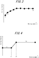
FIG. 3 is a diagram explaining a case of setting coiling tension for each winding number of a coil, when calculating a coiling tension pattern; -
FIG. 4 is a diagram explaining a case of setting coiling tension using parameters, when calculating a coiling tension pattern; -
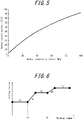
FIG. 5 is a diagram illustrating the pressure dependence of the elastic modulus in the radial direction of a coil measured using stacked steel sheets in Example 1; -
FIG. 6 is a diagram explaining parameters representing a coiling tension pattern set in Example 1; -
FIG. 7 is a diagram illustrating a coiling tension pattern obtained by optimization calculation in Example 1; -
FIG. 8 is a diagram explaining parameters representing a coiling tension pattern set in Example 1; and -
FIG. 9 is a diagram illustrating a coiling tension pattern obtained by optimization calculation in Example 2. - One of the disclosed embodiments will be described below, with reference to the drawings. A method of determining a tension pattern according to the present disclosure is a method of determining a tension pattern of tension applied to a steel sheet to coil the steel sheet in coil form, comprising calculating the tension pattern using an apparent elastic modulus in a radial direction of a coil.
- First, the reason why the apparent elastic modulus in the radial direction of the coil is used to determine the tension pattern applied to the steel sheet when coiling the steel sheet will be described below. Typically, when a steel sheet is coiled in coil form, even if there is no coating on the steel sheet surface, an air layer is present between the layers of the coil due to air entrainment or unevenness of the steel sheet surface. The presence of such an air layer causes the actual (apparent) elastic modulus in the radial direction of the coil to be lower than the elastic modulus of the bulk steel sheet.
- Here, consider the case of further winding, on an outermost winding portion of a coil obtained by coiling a steel sheet, one layer of the steel sheet. Due to the tension applied to the steel sheet additionally coiled, the outermost winding portion of the coil already formed by coiling the steel sheet is subjected to pressure in the radial direction of the coil. This pressure in the radial direction changes the stress state in the coil already formed by coiling the steel sheet. The amount of the change varies depending on the apparent elastic modulus in the radial direction. Hence, if the apparent elastic modulus in the coil radial direction is different, even when the steel sheet is coiled under the same conditions, the stress state in the coil after the coiling is different.
- Since collapsing and kinking of a coil each occur depending on the stress state in the coil, the difference in the apparent elastic modulus in the coil radial direction influences the occurrence of collapsing and kinking of the coil. Accordingly, by appropriately controlling the stress state in the coil after the coiling based on the apparent elastic modulus in the coil radial direction, the coil can be prevented from collapsing and kinking.
- As the apparent elastic modulus in the coil radial direction used in the determination of the coiling tension pattern of the steel sheet, a value obtained through actual measurement is preferably used, but it is also possible to use a value assumed to approximate the apparent elastic modulus in the coil radial direction from experience and the like. The apparent elastic modulus in the coil radial direction is preferably measured in a state in which the steel sheet is coiled in coil form. Alternatively, the apparent elastic modulus in the coil radial direction may be measured using a laminate obtained by stacking steel sheets in the sheet thickness direction, to simplify measurement.
- As an example, a method of measuring the apparent elastic modulus in the coil radial direction by stacking a plurality of steel sheets in the sheet thickness direction will be described below.
FIG. 1 is a schematic diagram explaining a method of measuring the apparent elastic modulus in the coil radial direction. Specifically, first, ablock 1 obtained by stacking a plurality of steel sheets in the sheet thickness direction is sandwiched betweenpads 2.Pressure 3 is then applied in the sheet thickness direction, andstrain 4 in the sheet thickness direction of theblock 1 is measured. Based on the measuredstrain 4, the elastic modulus in the sheet thickness direction of theblock 1 is calculated. Thus, the apparent elastic modulus in the coil radial direction can be approximately calculated. - In the case where the number of steel sheets stacked in the
block 1 is excessively small relative to the winding number (i.e. the number of turns) of the actual coil, the calculated elastic modulus in the coil radial direction deviates from the actual elastic modulus. The number of steel sheets stacked is therefore preferably not less than 20 % of the winding number of the coil. - The method of measuring the
strain 4 in the sheet thickness direction is not limited. Examples of the method include sandwiching a clip gauge between thepads 2 to measure the strain, and attaching a strain gauge to a side surface of theblock 1 to measure the strain. - Regarding the
pressure 3 applied to theblock 1, in the case where the air layer or coating between the layers of the coil is very thin or Young's modulus of the coil is close to the Young's modulus of iron and the apparent elastic modulus is not pressure-dependent, the elastic modulus measured with pressure at one appropriate point may be used as a representative value (elastic modulus) of the coil. In the case where a coating layer sufficiently softer than iron, such as a coating or slurry, is present on the steel sheet surface, however, the elastic modulus may vary significantly depending on the pressure. In such a case, it is preferable to measure the elastic modulus as a function with respect to thepressure 3. In the case where the elastic modulus is measured as a function with respect to thepressure 3, the measured elastic modulus itself or an approximate value obtained by fitting the measured elastic modulus to an appropriate function may be used when calculating coiling tension. - A method of calculating a coiling tension pattern of a steel sheet when coiling the steel sheet into a coil will be described below. As mentioned above, kinking and collapsing of a coil occur depending on the stress state in the coil after the steel sheet is coiled in coil form and the coil is removed from the mandrel. Hence, in the present disclosure, a model for predicting an in-coil stress distribution after coiling from a coiling tension pattern of a steel sheet is built, and a coiling tension pattern is determined using the model so as to achieve a desired in-coil stress distribution. Since the in-coil stress distribution depends on the apparent elastic modulus in the coil radial direction, the prediction model needs to be built using the apparent elastic modulus in the coil radial direction.
- An example of the in-coil stress distribution prediction model will be described below. In this prediction model, coiling a steel sheet is regarded as stacking thin-walled cylinders as illustrated in
FIG. 2 , and, each time the steel sheet is coiled (wound) for one layer, the stress in the coil that has already been formed is updated to obtain the stress state after the coiling. - When the radial stress in a state in which the steel sheet is coiled from the cylinder of the
innermost layer 6 of the coil as the first layer to the cylinder of theoutermost layer 7 of the coil as the nth layer on amandrel 5 inFIG. 2 is σr, the formula of equilibrium in the coil satisfies the following Formula (1):
- Here, r is the radial position in the coil. Moreover, g(σr)2 = Eθ/Er(σr), where Eθ is the elastic modulus in the circumferential direction of the coil, and Er(σr) is the apparent elastic modulus in the radial direction of the coil. As the value of Er(σr), a value actually measured by any of the foregoing methods is preferably used.
- Suppose, when the steel sheet of the (n + 1)th layer is wound around the outermost winding portion of the coil in an equilibrium state with tension T, the radial stress of the coil portion from the first layer to the nth layer changes to σr + δσr. Stress increment δσr follows the following Formula (2):

- Here, in the outermost winding portion r = rs and the innermost winding portion r = rc of the coil, the following Formulas (3) and (4) representing boundary conditions are satisfied:


- Δr is the sheet thickness of the steel sheet. By repeatedly performing, each time the steel sheet is coiled for one layer, an operation of adding stress increment δσr in the coil based on the foregoing formulas until a predetermined winding number is reached, stress distribution σr on in the coil after the coiling of the steel sheet is completed is obtained. Assuming that the stress distribution in the coil after the removal from the mandrel is σr off = σr on + δσr, stress increment δσr from σr on is obtained by calculating Formula (2) under the following Formulas (5) and (6) representing boundary conditions:


- Stress distribution σθ in the coil circumferential direction can be calculated using the following Formula (7):

- With the foregoing method, the stress distribution in the coil after the removal from the mandrel is obtained. Hence, the coiling tension pattern of the steel sheet can be changed so that the stress state in the coil will have such a distribution that is suitable for preventing kinking and collapsing. The model for predicting the stress distribution in the coil is not limited to the above-described model as long as it is a model based on the elastic modulus in the coil radial direction, and may be, for example, a method using finite element method (FEM) analysis or the like.
- The method of determining an appropriate coiling tension pattern is not limited as long as a desired stress state is achieved. An example is a method of performing optimization calculation using a coiling tension pattern as an input variable and a parameter relating to kinking and collapsing and an operation condition in an actual line as an objective variable or a constraint condition. For the coiling tension pattern as the input variable, a sequence of discrete coiling tension values for the respective winding numbers n may be given, as illustrated in
FIG. 3 . Alternatively, a simpler method of giving, as parameters, coiling tension values and each winding number n at which tension is changed may be used, as illustrated inFIG. 4 . - The objective variable in the optimization calculation of the coiling tension pattern of the steel sheet is selected so as to be a condition with which either or both of kinking and collapsing can be prevented. As the constraint condition, a condition with which kinking or collapsing can be prevented and that is not given as the objective variable and a range of operation condition possible in a production line are given according to need. The constraint condition as the operation condition may be a condition appropriate for the corresponding production line. Examples include the upper limit and lower limit of the coiling tension, and the upper limit and lower limit of the change rate of the coiling tension.
- A method of determining an item as the objective variable or the constraint condition when determining the stress distribution in the coil will be described below. Kinking is a defect in which the steel sheet buckles and protrudes inward in the radial direction in the case where the circumferential stress of the coil inner winding portion is strong compressive stress. From the viewpoint of preventing kinking, it is effective to give the circumferential stress in the coil as the objective variable or the constraint condition. Specifically, in the case where compressive stress is expressed as negative value, a condition that the circumferential stress of the coil innermost winding portion is not less than a certain value may be used. Alternatively, the integral value, maximum value, or minimum value of circumferential stress from the coil innermost winding portion to a given radial position may be used.
- Collapsing is considered to occur because the radial compressive stress in the coil is weak and slippage between the layers of the coil occurs due to insufficient friction between the layers of the coil. From the viewpoint of preventing collapsing, it is effective to give the radial stress in the coil as the objective variable or the constraint condition. Specifically, in the case where compressive stress is expressed as negative value, a condition that the integral value of radial stress from the coil innermost winding portion to the coil outermost winding portion, expressed by the following Formula (8), is not greater than a certain value is used.

- In the case where a specific region of the coil influences collapsing, an integral value expressed by the following Formula (9), which is yielded by multiplying the integral value in Formula (8) by appropriate weighting factor w(r), may be used:

- When determining the coiling tension pattern of the steel sheet, both the circumferential stress distribution of the coil and the radial stress distribution of the coil may be used as the objective variable or the constraint condition. In the case where only one of kinking and collapsing is problematic, the one of kinking and collapsing may be used for the objective variable or the constraint condition.
- By determining the coiling tension pattern of the steel sheet using the apparent elastic modulus in the coil radial direction by the foregoing method, kinking and collapsing can both be prevented.
- The presently disclosed techniques are effective when the steel sheet coiled is a steel sheet commonly classified as a thin sheet with a sheet thickness of 3 mm or less. Since the likelihood of kinking and collapsing is higher when the sheet thickness is thinner, the presently disclosed techniques are particularly effective when the sheet thickness is 0.5 mm or less.
- The presently disclosed techniques that use the elastic modulus in the coil radial direction to determine the coiling tension pattern of the steel sheet are particularly effective in the case where the steel sheet has a coating layer on its surface. The coating layer formed on the steel sheet surface is typically softer than the steel sheet and causes a decrease in the apparent elastic modulus in the coil radial direction. In such a case, the stress distribution in the coil significantly differs from the case where the elastic modulus in the coil radial direction is assumed to be the elastic modulus of the bulk steel sheet. Hence, the appropriate coiling tension pattern of the steel sheet is different, too.
- Examples of the coating layer on the steel sheet surface include a hot-dip galvanizing or an electrogalvanized plating of a coated or plated steel sheet, a polyethylene terephthalate (PET) or polypropylene (PP) coating of a laminate steel sheet, an annealing separator applied after decarburization annealing of a grain-oriented electrical steel sheet and mainly containing magnesium oxide (MgO), and an insulating coating applied after final annealing of a non-oriented electrical steel sheet.
- Examples according to the present disclosure will be described below, although the present disclosure is not limited to such.
- 300 samples of 50 mm square were cut out from a cold-rolled steel sheet of 0.5 mm in sheet thickness. The 300 samples cut out were stacked in the sheet thickness direction without removing an annealing separator. By the method illustrated in
FIG. 1 , pressure was applied to the stacked steel sheets in the sheet thickness direction, and the strain in the sheet thickness direction of the stacked steel sheets was measured to measure the elastic modulus of the stacked steel sheets as the elastic modulus in the coil radial direction.FIG. 5 illustrates the elastic modulus in the coil radial direction against the measured stress in the coil radial direction. Using the obtained elastic modulus in the coil radial direction, the stress distribution in the coil was calculated by the foregoing prediction model using Formulas (1) to (7) under the coil conditions shown in Table 1, and the coiling tension pattern of the steel sheet was determined. Here, the coiling tension pattern was determined using, as parameters, three levels of tension T1, T2, and T3, coil winding numbers n1 and n2 at which a change in tension starts, and tension change rates α1 and α2 in tension change intervals, as illustrated inFIG. 6 .Table 1 Coil inner diameter Coil outer diameter Sheet thickness Elastic modulus in coil circumferential direction [mm] [mm] [mm] [GPa] 250 750 0.5 210 - The initial condition of each of these parameters and the upper and lower limits of the parameter as the constraint condition are shown in Table 2. Moreover, for the purpose of preventing kinking of the coil, an objective variable was set so as to maximize the circumferential stress of the coil innermost diameter portion, that is, minimize the compressive stress of the coil innermost diameter portion. Furthermore, from the viewpoint of preventing collapsing of the coil, while the integral value of the radial stress in the coil expressed by Formula (8) when coiling the steel sheet under the initial conditions shown in Table 2 is -340 MPa·mm, a constraint condition that the integral value is -350 MPa·mm or less was added as a condition for further preventing collapsing.
Table 2 T1 [MPa] T2 [MPa] T3 [MPa] n1 n2 α1 [MPa/mm] α2 [MPa/mm] Initial condition 30 30 30 100 1000 0.1 0.1 Upper limit 5 5 5 1 1 0.001 0.001 Lower limit 80 80 80 1000 1000 1 1 -
FIG. 7 illustrates a tension pattern obtained as a result of optimization calculation based on these conditions. In Example 1, a pattern in which the steel sheet is coiled with the lower-limit tension in the initial stage and then the coiling tension is increased gradually and, at some midpoint, the coiling tension increase rate is lowered was found to be optimum for prevention of coil collapsing. The circumferential compressive stress of the coil innermost winding portion before the optimization was 18 MPa, which was reduced to 3.1 MPa after the optimization. - As a result of coiling the steel sheet using the tension pattern determined in this way, the steel sheet was able to be coiled without kinking and collapsing.
- 300 samples of 50 mm square were cut out from a steel sheet obtained by decarburization annealing a grain-oriented electrical steel sheet of 0.23 mm in sheet thickness and then applying an annealing separator mainly containing MgO to both sides (surfaces) of the steel sheet. The 300 samples cut out were stacked in the sheet thickness direction without removing the annealing separator. By the method illustrated in
FIG. 1 , pressure was applied to the stacked steel sheets in the sheet thickness direction, and the strain in the sheet thickness direction of the stacked steel sheets was measured to measure the elastic modulus of the stacked steel sheets as the elastic modulus in the coil radial direction.FIG. 8 illustrates the elastic modulus in the coil radial direction against the measured stress in the coil radial direction. Using the obtained elastic modulus in the coil radial direction, the stress distribution in the coil was calculated by the foregoing prediction model using Formulas (1) to (7) under the coil conditions shown in Table 3, and the coiling tension pattern was determined. Here, the coiling tension pattern was determined using the parameters illustrated inFIG. 6 , as in Example 1.Table 3 Coil inner diameter Coil outer diameter Sheet thickness Elastic modulus in coil circumferential direction [mm] [mm] [mm] [GPa] 250 640 0.23 210 - The initial condition of each of these parameters and the upper and lower limits of the parameter as the constraint condition are shown in Table 4. Moreover, for the purpose of preventing kinking of the coil, an objective variable was set so as to maximize the circumferential stress of the coil innermost diameter portion, that is, minimize the compressive stress of the coil innermost diameter portion. Furthermore, from the viewpoint of preventing collapsing of the coil, while the integral value of the radial stress in the coil expressed by Formula (8) when coiling the steel sheet under the initial conditions shown in Table 4 is -1210 MPa·mm, a constraint condition that the integral value is -1480 MPa·mm or less was added as a condition for further preventing collapsing.
Table 4 T1 [MPa] T2 [MPa] T3 [MPa] n1 n2 α1 MPa/mm α2 MPa/mm Initial condition 100 100 100 100 1000 0.1 0.1 Upper limit 80 80 80 1 1 0.01 0.01 Lower limit 130 130 130 1000 1260 0.5 0.5 -
FIG. 9 illustrates a tension pattern obtained as a result of optimization calculation based on these conditions. In Example 2, a pattern in which the steel sheet is coiled with the lower-limit tension in the initial stage and then the coiling tension is increased gradually and, at some midpoint, the tension is raised to the upper limit was found to be optimum for prevention of coil kinking and collapsing. The circumferential compressive stress of the coil innermost winding portion before the optimization was 69 MPa, which was reduced to 29 MPa after the optimization. - As a result of coiling the steel sheet to which MgO was applied as the annealing separator using the tension pattern determined in this way, the steel sheet was able to be coiled without kinking and collapsing.
- The presently disclosed techniques can prevent either or both of kinking and collapsing of a steel sheet coiled in coil form regardless of the characteristics of the steel sheet, and thus are useful in ironmaking.
-
- 1
- stacked steel sheets
- 2
- pad
- 3
- pressure
- 4
- height of stacked steel sheets
- 5
- mandrel
- 6
- coil innermost layer
- 7
- coil outermost layer
Claims (6)
- A method of determining a tension pattern of tension applied to a steel sheet to coil the steel sheet in coil form, the method comprising
calculating the tension pattern using an apparent elastic modulus in a radial direction of a coil. - The method of determining a tension pattern according to claim 1, wherein when calculating the tension pattern, circumferential stress in the coil is used as an objective variable or a constraint condition.
- The method of determining a tension pattern according to claim 1 or 2, wherein when calculating the tension pattern, radial stress in the coil is used as an objective variable or a constraint condition.
- The method of determining a tension pattern according to any one of claims 1 to 3, wherein a sheet thickness of the steel sheet is 0.5 mm or less.
- The method of determining a tension pattern according to any one of claims 1 to 4, wherein the steel sheet has a coating layer on at least one surface thereof.
- A method of coiling a steel sheet, the method comprising:determining a tension pattern of tension applied to the steel sheet when coiling the steel sheet in coil form, by the method of determining a tension pattern according to any one of claims 1 to 5; andcoiling the steel sheet in coil form according to the determined tension pattern.
Applications Claiming Priority (2)
| Application Number | Priority Date | Filing Date | Title |
|---|---|---|---|
| JP2020087707 | 2020-05-19 | ||
| PCT/JP2021/019066 WO2021235498A1 (en) | 2020-05-19 | 2021-05-19 | Determination method for tension pattern and roll-up method for steel sheet |
Publications (3)
| Publication Number | Publication Date |
|---|---|
| EP4155002A1 true EP4155002A1 (en) | 2023-03-29 |
| EP4155002A4 EP4155002A4 (en) | 2023-11-15 |
| EP4155002B1 EP4155002B1 (en) | 2024-12-25 |
Family
ID=78707900
Family Applications (1)
| Application Number | Title | Priority Date | Filing Date |
|---|---|---|---|
| EP21808193.3A Active EP4155002B1 (en) | 2020-05-19 | 2021-05-19 | Method of determining tension pattern and method of coiling steel sheet |
Country Status (6)
| Country | Link |
|---|---|
| US (1) | US12440880B2 (en) |
| EP (1) | EP4155002B1 (en) |
| JP (1) | JP7126102B2 (en) |
| KR (1) | KR102904965B1 (en) |
| CN (1) | CN115551653A (en) |
| WO (1) | WO2021235498A1 (en) |
Family Cites Families (13)
| Publication number | Priority date | Publication date | Assignee | Title |
|---|---|---|---|---|
| JPS4642692B1 (en) | 1968-06-07 | 1971-12-17 | ||
| JPS6270523A (en) | 1985-09-25 | 1987-04-01 | Kawasaki Steel Corp | Box annealing method for grain oriented silicon steel sheet coil |
| JPS63140035A (en) | 1986-11-29 | 1988-06-11 | Kawasaki Steel Corp | Production of light-gage grain oriented silicon steel sheet |
| JPH0733198B2 (en) * | 1987-05-20 | 1995-04-12 | 富士写真フイルム株式会社 | Web winding method |
| JP2717022B2 (en) | 1990-09-21 | 1998-02-18 | 川崎製鉄株式会社 | Box annealing method for grain oriented silicon steel sheet coil |
| JPH0671337A (en) | 1992-08-27 | 1994-03-15 | Nkk Corp | Winding method for steel sheet |
| DE10323811A1 (en) * | 2003-05-23 | 2005-01-13 | Bwg Bergwerk- Und Walzwerk-Maschinenbau Gmbh | Method for the continuous drawing of metallic strips and drawstring line |
| JP5927754B2 (en) * | 2010-06-29 | 2016-06-01 | Jfeスチール株式会社 | Oriented electrical steel sheet and manufacturing method thereof |
| JP2012017159A (en) * | 2010-07-06 | 2012-01-26 | Lintec Corp | Analysis program of thickness of each air layer in winding roll, radial young's modulus of air layer, and internal stress |
| JP5748514B2 (en) | 2011-03-10 | 2015-07-15 | 富士機械工業株式会社 | Winding device and winding control method |
| JP5461605B2 (en) * | 2012-03-02 | 2014-04-02 | 富士フイルム株式会社 | Web roll manufacturing method, web roll winding method and internal stress calculation method |
| CN104275368B (en) * | 2014-09-15 | 2015-12-09 | 燕山大学 | A comprehensive optimization calculation method for uncoiling tension of hot-rolled strip steel |
| JP6240697B2 (en) | 2016-03-16 | 2017-11-29 | 住友化学株式会社 | Separator winding body |
-
2021
- 2021-05-19 WO PCT/JP2021/019066 patent/WO2021235498A1/en not_active Ceased
- 2021-05-19 JP JP2021542211A patent/JP7126102B2/en active Active
- 2021-05-19 US US17/998,807 patent/US12440880B2/en active Active
- 2021-05-19 KR KR1020227039885A patent/KR102904965B1/en active Active
- 2021-05-19 EP EP21808193.3A patent/EP4155002B1/en active Active
- 2021-05-19 CN CN202180035064.3A patent/CN115551653A/en active Pending
Also Published As
| Publication number | Publication date |
|---|---|
| JP7126102B2 (en) | 2022-08-26 |
| KR20220161563A (en) | 2022-12-06 |
| EP4155002A4 (en) | 2023-11-15 |
| JPWO2021235498A1 (en) | 2021-11-25 |
| EP4155002B1 (en) | 2024-12-25 |
| WO2021235498A1 (en) | 2021-11-25 |
| CN115551653A (en) | 2022-12-30 |
| KR102904965B1 (en) | 2025-12-26 |
| US20230234116A1 (en) | 2023-07-27 |
| US12440880B2 (en) | 2025-10-14 |
Similar Documents
| Publication | Publication Date | Title |
|---|---|---|
| CN113369302B (en) | Medium carbon steel 65Mn and coiling control method and control system thereof | |
| JP6052412B2 (en) | Steel plate for can and manufacturing method thereof | |
| CN109848247B (en) | Cold-rolled strip steel coiling tension control method and control device thereof | |
| JP4919857B2 (en) | Manufacturing method of single-sided taper steel plate whose thickness changes in a taper shape in the rolling direction | |
| EP2933033B1 (en) | A production method for a flat metal plate | |
| CN1332807A (en) | Steel band with good forming properties and method for producing same | |
| EP4155002B1 (en) | Method of determining tension pattern and method of coiling steel sheet | |
| JP5626172B2 (en) | Steel strip manufacturing equipment | |
| EP0289064B1 (en) | A method of rolling strip in a rolling mill and a control system therefor | |
| KR101031745B1 (en) | Manufacturing method of aluminum strip with excellent planarity | |
| Park et al. | Effects of processing parameters on elastic deformation of the coil during the thin-strip coiling process | |
| CN113020319A (en) | Strip steel leveling process method and production line | |
| US20090258228A1 (en) | Steel wire for spring | |
| JP6870359B2 (en) | Arithmetic logic unit and arithmetic method | |
| EP4306230A1 (en) | Method for manufacturing cold-rolled steel sheet, and manufacturing facility | |
| KR20250037478A (en) | Method for manufacturing cold rolled steel strip | |
| KR101198474B1 (en) | Method of roll force prediction in cold rolling of stainless steels | |
| JP2004283900A (en) | Steel sheet winding method | |
| JP2004530563A (en) | Method for preventing strip sticker during coil winding and strip processing equipment, in particular strip rolling mill row or strip rolling stand | |
| JP3045465B2 (en) | Control method of thickness of stainless steel sheet | |
| JP6287911B2 (en) | Cold rolling equipment and manufacturing method for steel strip | |
| JP6536646B2 (en) | Cold-rolled steel sheet manufacturing method and cold-rolled steel sheet manufacturing equipment | |
| JPS63130938A (en) | Spiral spring | |
| CN115301760B (en) | A method for predicting and controlling the formation of inner edge waves during cold coiling of strip steel. | |
| CN121649245A (en) | Method, device, equipment and medium for producing band steel |
Legal Events
| Date | Code | Title | Description |
|---|---|---|---|
| STAA | Information on the status of an ep patent application or granted ep patent |
Free format text: STATUS: THE INTERNATIONAL PUBLICATION HAS BEEN MADE |
|
| PUAI | Public reference made under article 153(3) epc to a published international application that has entered the european phase |
Free format text: ORIGINAL CODE: 0009012 |
|
| STAA | Information on the status of an ep patent application or granted ep patent |
Free format text: STATUS: REQUEST FOR EXAMINATION WAS MADE |
|
| 17P | Request for examination filed |
Effective date: 20221201 |
|
| AK | Designated contracting states |
Kind code of ref document: A1 Designated state(s): AL AT BE BG CH CY CZ DE DK EE ES FI FR GB GR HR HU IE IS IT LI LT LU LV MC MK MT NL NO PL PT RO RS SE SI SK SM TR |
|
| DAV | Request for validation of the european patent (deleted) | ||
| DAX | Request for extension of the european patent (deleted) | ||
| A4 | Supplementary search report drawn up and despatched |
Effective date: 20231013 |
|
| RIC1 | Information provided on ipc code assigned before grant |
Ipc: B21C 47/04 20060101ALI20231009BHEP Ipc: B21C 47/34 20060101ALI20231009BHEP Ipc: B65H 23/195 20060101ALI20231009BHEP Ipc: C21D 8/12 20060101ALI20231009BHEP Ipc: B21C 47/02 20060101ALI20231009BHEP Ipc: B21C 47/00 20060101AFI20231009BHEP |
|
| RIC1 | Information provided on ipc code assigned before grant |
Ipc: B21C 47/04 20060101ALI20240710BHEP Ipc: B21C 47/34 20060101ALI20240710BHEP Ipc: B65H 23/195 20060101ALI20240710BHEP Ipc: C21D 8/12 20060101ALI20240710BHEP Ipc: B21C 47/02 20060101ALI20240710BHEP Ipc: B21C 47/00 20060101AFI20240710BHEP |
|
| GRAP | Despatch of communication of intention to grant a patent |
Free format text: ORIGINAL CODE: EPIDOSNIGR1 |
|
| STAA | Information on the status of an ep patent application or granted ep patent |
Free format text: STATUS: GRANT OF PATENT IS INTENDED |
|
| INTG | Intention to grant announced |
Effective date: 20240820 |
|
| GRAS | Grant fee paid |
Free format text: ORIGINAL CODE: EPIDOSNIGR3 |
|
| GRAA | (expected) grant |
Free format text: ORIGINAL CODE: 0009210 |
|
| STAA | Information on the status of an ep patent application or granted ep patent |
Free format text: STATUS: THE PATENT HAS BEEN GRANTED |
|
| AK | Designated contracting states |
Kind code of ref document: B1 Designated state(s): AL AT BE BG CH CY CZ DE DK EE ES FI FR GB GR HR HU IE IS IT LI LT LU LV MC MK MT NL NO PL PT RO RS SE SI SK SM TR |
|
| REG | Reference to a national code |
Ref country code: GB Ref legal event code: FG4D |
|
| RIN1 | Information on inventor provided before grant (corrected) |
Inventor name: WATANABE, RYOSUKE Inventor name: WATANABE, NAOKI Inventor name: SUEHIRO, RYUICHI |
|
| REG | Reference to a national code |
Ref country code: CH Ref legal event code: EP |
|
| REG | Reference to a national code |
Ref country code: DE Ref legal event code: R096 Ref document number: 602021023987 Country of ref document: DE |
|
| REG | Reference to a national code |
Ref country code: IE Ref legal event code: FG4D |
|
| REG | Reference to a national code |
Ref country code: LT Ref legal event code: MG9D |
|
| PG25 | Lapsed in a contracting state [announced via postgrant information from national office to epo] |
Ref country code: HR Free format text: LAPSE BECAUSE OF FAILURE TO SUBMIT A TRANSLATION OF THE DESCRIPTION OR TO PAY THE FEE WITHIN THE PRESCRIBED TIME-LIMIT Effective date: 20241225 |
|
| PG25 | Lapsed in a contracting state [announced via postgrant information from national office to epo] |
Ref country code: FI Free format text: LAPSE BECAUSE OF FAILURE TO SUBMIT A TRANSLATION OF THE DESCRIPTION OR TO PAY THE FEE WITHIN THE PRESCRIBED TIME-LIMIT Effective date: 20241225 |
|
| PG25 | Lapsed in a contracting state [announced via postgrant information from national office to epo] |
Ref country code: BG Free format text: LAPSE BECAUSE OF FAILURE TO SUBMIT A TRANSLATION OF THE DESCRIPTION OR TO PAY THE FEE WITHIN THE PRESCRIBED TIME-LIMIT Effective date: 20241225 |
|
| PG25 | Lapsed in a contracting state [announced via postgrant information from national office to epo] |
Ref country code: NO Free format text: LAPSE BECAUSE OF FAILURE TO SUBMIT A TRANSLATION OF THE DESCRIPTION OR TO PAY THE FEE WITHIN THE PRESCRIBED TIME-LIMIT Effective date: 20250325 |
|
| PG25 | Lapsed in a contracting state [announced via postgrant information from national office to epo] |
Ref country code: GR Free format text: LAPSE BECAUSE OF FAILURE TO SUBMIT A TRANSLATION OF THE DESCRIPTION OR TO PAY THE FEE WITHIN THE PRESCRIBED TIME-LIMIT Effective date: 20250326 Ref country code: LV Free format text: LAPSE BECAUSE OF FAILURE TO SUBMIT A TRANSLATION OF THE DESCRIPTION OR TO PAY THE FEE WITHIN THE PRESCRIBED TIME-LIMIT Effective date: 20241225 |
|
| PG25 | Lapsed in a contracting state [announced via postgrant information from national office to epo] |
Ref country code: RS Free format text: LAPSE BECAUSE OF FAILURE TO SUBMIT A TRANSLATION OF THE DESCRIPTION OR TO PAY THE FEE WITHIN THE PRESCRIBED TIME-LIMIT Effective date: 20250325 |
|
| REG | Reference to a national code |
Ref country code: NL Ref legal event code: MP Effective date: 20241225 |
|
| PG25 | Lapsed in a contracting state [announced via postgrant information from national office to epo] |
Ref country code: NL Free format text: LAPSE BECAUSE OF FAILURE TO SUBMIT A TRANSLATION OF THE DESCRIPTION OR TO PAY THE FEE WITHIN THE PRESCRIBED TIME-LIMIT Effective date: 20241225 |
|
| REG | Reference to a national code |
Ref country code: AT Ref legal event code: MK05 Ref document number: 1753751 Country of ref document: AT Kind code of ref document: T Effective date: 20241225 |
|
| PG25 | Lapsed in a contracting state [announced via postgrant information from national office to epo] |
Ref country code: SM Free format text: LAPSE BECAUSE OF FAILURE TO SUBMIT A TRANSLATION OF THE DESCRIPTION OR TO PAY THE FEE WITHIN THE PRESCRIBED TIME-LIMIT Effective date: 20241225 |
|
| PG25 | Lapsed in a contracting state [announced via postgrant information from national office to epo] |
Ref country code: PL Free format text: LAPSE BECAUSE OF FAILURE TO SUBMIT A TRANSLATION OF THE DESCRIPTION OR TO PAY THE FEE WITHIN THE PRESCRIBED TIME-LIMIT Effective date: 20241225 |
|
| PGFP | Annual fee paid to national office [announced via postgrant information from national office to epo] |
Ref country code: DE Payment date: 20250520 Year of fee payment: 5 |
|
| PG25 | Lapsed in a contracting state [announced via postgrant information from national office to epo] |
Ref country code: ES Free format text: LAPSE BECAUSE OF FAILURE TO SUBMIT A TRANSLATION OF THE DESCRIPTION OR TO PAY THE FEE WITHIN THE PRESCRIBED TIME-LIMIT Effective date: 20241225 |
|
| PG25 | Lapsed in a contracting state [announced via postgrant information from national office to epo] |
Ref country code: IS Free format text: LAPSE BECAUSE OF FAILURE TO SUBMIT A TRANSLATION OF THE DESCRIPTION OR TO PAY THE FEE WITHIN THE PRESCRIBED TIME-LIMIT Effective date: 20250425 |
|
| PG25 | Lapsed in a contracting state [announced via postgrant information from national office to epo] |
Ref country code: PT Free format text: LAPSE BECAUSE OF FAILURE TO SUBMIT A TRANSLATION OF THE DESCRIPTION OR TO PAY THE FEE WITHIN THE PRESCRIBED TIME-LIMIT Effective date: 20250428 |
|
| PG25 | Lapsed in a contracting state [announced via postgrant information from national office to epo] |
Ref country code: EE Free format text: LAPSE BECAUSE OF FAILURE TO SUBMIT A TRANSLATION OF THE DESCRIPTION OR TO PAY THE FEE WITHIN THE PRESCRIBED TIME-LIMIT Effective date: 20241225 |
|
| PGFP | Annual fee paid to national office [announced via postgrant information from national office to epo] |
Ref country code: FR Payment date: 20250522 Year of fee payment: 5 |
|
| PG25 | Lapsed in a contracting state [announced via postgrant information from national office to epo] |
Ref country code: AT Free format text: LAPSE BECAUSE OF FAILURE TO SUBMIT A TRANSLATION OF THE DESCRIPTION OR TO PAY THE FEE WITHIN THE PRESCRIBED TIME-LIMIT Effective date: 20241225 Ref country code: RO Free format text: LAPSE BECAUSE OF FAILURE TO SUBMIT A TRANSLATION OF THE DESCRIPTION OR TO PAY THE FEE WITHIN THE PRESCRIBED TIME-LIMIT Effective date: 20241225 |
|
| PG25 | Lapsed in a contracting state [announced via postgrant information from national office to epo] |
Ref country code: SK Free format text: LAPSE BECAUSE OF FAILURE TO SUBMIT A TRANSLATION OF THE DESCRIPTION OR TO PAY THE FEE WITHIN THE PRESCRIBED TIME-LIMIT Effective date: 20241225 |
|
| PG25 | Lapsed in a contracting state [announced via postgrant information from national office to epo] |
Ref country code: CZ Free format text: LAPSE BECAUSE OF FAILURE TO SUBMIT A TRANSLATION OF THE DESCRIPTION OR TO PAY THE FEE WITHIN THE PRESCRIBED TIME-LIMIT Effective date: 20241225 |
|
| PG25 | Lapsed in a contracting state [announced via postgrant information from national office to epo] |
Ref country code: IT Free format text: LAPSE BECAUSE OF FAILURE TO SUBMIT A TRANSLATION OF THE DESCRIPTION OR TO PAY THE FEE WITHIN THE PRESCRIBED TIME-LIMIT Effective date: 20241225 |
|
| PG25 | Lapsed in a contracting state [announced via postgrant information from national office to epo] |
Ref country code: SE Free format text: LAPSE BECAUSE OF FAILURE TO SUBMIT A TRANSLATION OF THE DESCRIPTION OR TO PAY THE FEE WITHIN THE PRESCRIBED TIME-LIMIT Effective date: 20241225 |
|
| REG | Reference to a national code |
Ref country code: DE Ref legal event code: R097 Ref document number: 602021023987 Country of ref document: DE |
|
| PG25 | Lapsed in a contracting state [announced via postgrant information from national office to epo] |
Ref country code: DK Free format text: LAPSE BECAUSE OF FAILURE TO SUBMIT A TRANSLATION OF THE DESCRIPTION OR TO PAY THE FEE WITHIN THE PRESCRIBED TIME-LIMIT Effective date: 20241225 |
|
| PLBE | No opposition filed within time limit |
Free format text: ORIGINAL CODE: 0009261 |
|
| STAA | Information on the status of an ep patent application or granted ep patent |
Free format text: STATUS: NO OPPOSITION FILED WITHIN TIME LIMIT |
|
| REG | Reference to a national code |
Ref country code: CH Ref legal event code: L10 Free format text: ST27 STATUS EVENT CODE: U-0-0-L10-L00 (AS PROVIDED BY THE NATIONAL OFFICE) Effective date: 20251105 |
|
| 26N | No opposition filed |
Effective date: 20250926 |
|
| REG | Reference to a national code |
Ref country code: CH Ref legal event code: H13 Free format text: ST27 STATUS EVENT CODE: U-0-0-H10-H13 (AS PROVIDED BY THE NATIONAL OFFICE) Effective date: 20251223 |
|
| PG25 | Lapsed in a contracting state [announced via postgrant information from national office to epo] |
Ref country code: LU Free format text: LAPSE BECAUSE OF NON-PAYMENT OF DUE FEES Effective date: 20250519 |
|
| PG25 | Lapsed in a contracting state [announced via postgrant information from national office to epo] |
Ref country code: CH Free format text: LAPSE BECAUSE OF NON-PAYMENT OF DUE FEES Effective date: 20250531 |
|
| GBPC | Gb: european patent ceased through non-payment of renewal fee |
Effective date: 20250519 |
|
| REG | Reference to a national code |
Ref country code: BE Ref legal event code: MM Effective date: 20250531 |
|
| PG25 | Lapsed in a contracting state [announced via postgrant information from national office to epo] |
Ref country code: MC Free format text: LAPSE BECAUSE OF FAILURE TO SUBMIT A TRANSLATION OF THE DESCRIPTION OR TO PAY THE FEE WITHIN THE PRESCRIBED TIME-LIMIT Effective date: 20241225 |
|
| PG25 | Lapsed in a contracting state [announced via postgrant information from national office to epo] |
Ref country code: GB Free format text: LAPSE BECAUSE OF NON-PAYMENT OF DUE FEES Effective date: 20250519 |
|
| PG25 | Lapsed in a contracting state [announced via postgrant information from national office to epo] |
Ref country code: IE Free format text: LAPSE BECAUSE OF NON-PAYMENT OF DUE FEES Effective date: 20250519 |
|
| PG25 | Lapsed in a contracting state [announced via postgrant information from national office to epo] |
Ref country code: BE Free format text: LAPSE BECAUSE OF NON-PAYMENT OF DUE FEES Effective date: 20250531 |