EP4154994A1 - Slot die coater - Google Patents
Slot die coater Download PDFInfo
- Publication number
- EP4154994A1 EP4154994A1 EP21886820.6A EP21886820A EP4154994A1 EP 4154994 A1 EP4154994 A1 EP 4154994A1 EP 21886820 A EP21886820 A EP 21886820A EP 4154994 A1 EP4154994 A1 EP 4154994A1
- Authority
- EP
- European Patent Office
- Prior art keywords
- slot
- die
- shim plate
- active material
- coating
- Prior art date
- Legal status (The legal status is an assumption and is not a legal conclusion. Google has not performed a legal analysis and makes no representation as to the accuracy of the status listed.)
- Pending
Links
Images





Classifications
-
- B—PERFORMING OPERATIONS; TRANSPORTING
- B05—SPRAYING OR ATOMISING IN GENERAL; APPLYING FLUENT MATERIALS TO SURFACES, IN GENERAL
- B05C—APPARATUS FOR APPLYING FLUENT MATERIALS TO SURFACES, IN GENERAL
- B05C5/00—Apparatus in which liquid or other fluent material is projected, poured or allowed to flow on to the surface of the work
- B05C5/02—Apparatus in which liquid or other fluent material is projected, poured or allowed to flow on to the surface of the work the liquid or other fluent material being discharged through an outlet orifice by pressure, e.g. from an outlet device in contact or almost in contact, with the work
- B05C5/0254—Coating heads with slot-shaped outlet
-
- B—PERFORMING OPERATIONS; TRANSPORTING
- B05—SPRAYING OR ATOMISING IN GENERAL; APPLYING FLUENT MATERIALS TO SURFACES, IN GENERAL
- B05C—APPARATUS FOR APPLYING FLUENT MATERIALS TO SURFACES, IN GENERAL
- B05C5/00—Apparatus in which liquid or other fluent material is projected, poured or allowed to flow on to the surface of the work
- B05C5/02—Apparatus in which liquid or other fluent material is projected, poured or allowed to flow on to the surface of the work the liquid or other fluent material being discharged through an outlet orifice by pressure, e.g. from an outlet device in contact or almost in contact, with the work
- B05C5/0254—Coating heads with slot-shaped outlet
- B05C5/0262—Coating heads with slot-shaped outlet adjustable in width, i.e. having lips movable relative to each other in order to modify the slot width, e.g. to close it
-
- H—ELECTRICITY
- H01—ELECTRIC ELEMENTS
- H01M—PROCESSES OR MEANS, e.g. BATTERIES, FOR THE DIRECT CONVERSION OF CHEMICAL ENERGY INTO ELECTRICAL ENERGY
- H01M4/00—Electrodes
- H01M4/02—Electrodes composed of, or comprising, active material
- H01M4/04—Processes of manufacture in general
-
- H—ELECTRICITY
- H01—ELECTRIC ELEMENTS
- H01M—PROCESSES OR MEANS, e.g. BATTERIES, FOR THE DIRECT CONVERSION OF CHEMICAL ENERGY INTO ELECTRICAL ENERGY
- H01M4/00—Electrodes
- H01M4/02—Electrodes composed of, or comprising, active material
- H01M4/04—Processes of manufacture in general
- H01M4/0402—Methods of deposition of the material
- H01M4/0404—Methods of deposition of the material by coating on electrode collectors
-
- H—ELECTRICITY
- H01—ELECTRIC ELEMENTS
- H01M—PROCESSES OR MEANS, e.g. BATTERIES, FOR THE DIRECT CONVERSION OF CHEMICAL ENERGY INTO ELECTRICAL ENERGY
- H01M4/00—Electrodes
- H01M4/02—Electrodes composed of, or comprising, active material
- H01M4/04—Processes of manufacture in general
- H01M4/0402—Methods of deposition of the material
- H01M4/0409—Methods of deposition of the material by a doctor blade method, slip-casting or roller coating
-
- H—ELECTRICITY
- H01—ELECTRIC ELEMENTS
- H01M—PROCESSES OR MEANS, e.g. BATTERIES, FOR THE DIRECT CONVERSION OF CHEMICAL ENERGY INTO ELECTRICAL ENERGY
- H01M4/00—Electrodes
- H01M4/02—Electrodes composed of, or comprising, active material
- H01M4/04—Processes of manufacture in general
- H01M4/0402—Methods of deposition of the material
- H01M4/0411—Methods of deposition of the material by extrusion
-
- H—ELECTRICITY
- H01—ELECTRIC ELEMENTS
- H01M—PROCESSES OR MEANS, e.g. BATTERIES, FOR THE DIRECT CONVERSION OF CHEMICAL ENERGY INTO ELECTRICAL ENERGY
- H01M4/00—Electrodes
- H01M4/02—Electrodes composed of, or comprising, active material
- H01M4/13—Electrodes for accumulators with non-aqueous electrolyte, e.g. for lithium-accumulators; Processes of manufacture thereof
- H01M4/139—Processes of manufacture
-
- B—PERFORMING OPERATIONS; TRANSPORTING
- B05—SPRAYING OR ATOMISING IN GENERAL; APPLYING FLUENT MATERIALS TO SURFACES, IN GENERAL
- B05C—APPARATUS FOR APPLYING FLUENT MATERIALS TO SURFACES, IN GENERAL
- B05C9/00—Apparatus or plant for applying liquid or other fluent material to surfaces by means not covered by any preceding group, or in which the means of applying the liquid or other fluent material is not important
- B05C9/06—Apparatus or plant for applying liquid or other fluent material to surfaces by means not covered by any preceding group, or in which the means of applying the liquid or other fluent material is not important for applying two different liquids or other fluent materials, or the same liquid or other fluent material twice, to the same side of the work
-
- Y—GENERAL TAGGING OF NEW TECHNOLOGICAL DEVELOPMENTS; GENERAL TAGGING OF CROSS-SECTIONAL TECHNOLOGIES SPANNING OVER SEVERAL SECTIONS OF THE IPC; TECHNICAL SUBJECTS COVERED BY FORMER USPC CROSS-REFERENCE ART COLLECTIONS [XRACs] AND DIGESTS
- Y02—TECHNOLOGIES OR APPLICATIONS FOR MITIGATION OR ADAPTATION AGAINST CLIMATE CHANGE
- Y02E—REDUCTION OF GREENHOUSE GAS [GHG] EMISSIONS, RELATED TO ENERGY GENERATION, TRANSMISSION OR DISTRIBUTION
- Y02E60/00—Enabling technologies; Technologies with a potential or indirect contribution to GHG emissions mitigation
- Y02E60/10—Energy storage using batteries
-
- Y—GENERAL TAGGING OF NEW TECHNOLOGICAL DEVELOPMENTS; GENERAL TAGGING OF CROSS-SECTIONAL TECHNOLOGIES SPANNING OVER SEVERAL SECTIONS OF THE IPC; TECHNICAL SUBJECTS COVERED BY FORMER USPC CROSS-REFERENCE ART COLLECTIONS [XRACs] AND DIGESTS
- Y02—TECHNOLOGIES OR APPLICATIONS FOR MITIGATION OR ADAPTATION AGAINST CLIMATE CHANGE
- Y02P—CLIMATE CHANGE MITIGATION TECHNOLOGIES IN THE PRODUCTION OR PROCESSING OF GOODS
- Y02P70/00—Climate change mitigation technologies in the production process for final industrial or consumer products
- Y02P70/50—Manufacturing or production processes characterised by the final manufactured product
Definitions
- the present disclosure relates to a slot die coater, and more particularly to a slot die coater capable of uniformly forming a coating boundary formed in a machine direction (MD).
- MD machine direction
- Such secondary batteries essentially include an electrode assembly which is a power generation element.
- the electrode assembly has a form in which a positive electrode, a separator, and a negative electrode are stacked at least once, and the positive electrode and the negative electrode are prepared by applying and drying a positive electrode active material slurry and a negative electrode active material slurry on a current collector made of aluminum foil and copper foil, respectively.
- the positive electrode active material slurry and the negative electrode active material slurry should be uniformly coated on the current collector, and a slot die coater is conventionally used.
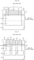
- FIG. 1 shows an example of a coating method using a conventional slot die coater.
- FIG. 2 is a cross-sectional view of the slot die coater taken along II-II' of FIG. 1 along a machine direction (MD) (a traveling direction of a current collector).
- MD machine direction
- an electrode active material slurry discharged from the slot die coater 30 is applied on an current collector 20 transferred by a coating roll 10.
- the electrode active material slurry discharged from the slot die coater 30 is widely applied on one surface of the current collector 20 to form an electrode active material layer.
- the slot die coater 30 includes two die blocks 32 and 34 and forms a slot 36 between the two die blocks 32 and 34.
- the electrode active material slurry supplied from a feed portion (not shown) is accommodated in a manifold 38, and discharged through a discharge port 40 communicatively connected to the slot 36, thereby forming the electrode active material layer.
- Reference numerals 42 and 44 denote die lips which are front ends of the die blocks 32 and 34, respectively.
- a coating width of the electrode active material layer coated on the current collector 20 is determined according to a width of the slot 36.
- various coating widths may be implemented by changing a shim plate 50 that determines an inner space of the manifold 38 and the width of the slot 36.
- FIGS. 3A to 3C schematically show examples of adjusting the coating width by varying the size and shape of the shim plate 50 inserted between the die blocks 32 and 34.
- the shim plate 50 includes an open portion 50a by cutting one region thereof and is interposed in the remaining parts except for one side of an edge region of an opposite surface of each of the die blocks 32 and 34.
- a width of the open portion 50a of the shim plate 50 is designed such that an electrode active material layer 60 having a coating width a is formed on the current collector 20, and uncoated portions 62 are formed on both sides of the electrode active material layer 60.
- the width of the open portion 50a of the shim plate 50 is designed as b.
- the electrode active material layer 60 having a stripe pattern shape may be formed on the current collector 20.
- the shim plate 50 as shown in FIG. 3C is used. Referring to FIG. 3C , a region of the shim plate 50 is intermittently cut so that the shim plate 50 includes a plurality of open portions 50a, and the width of the open portion 50a is c smaller than a or b.
- the electrode active material layer 60 having the coating width c is formed on the current collector 20 in a plurality of stripe pattern shapes as many as the number of the open portions 50a, and the uncoated portions 62 are formed on both sides of the electrode active material layer 60.
- a die lip 42 and the end of the shim plate 50 are aligned.
- a coating gap that is, a distance between the discharge port 40 of the slot die coater 30 and the current collector 20 (or a distance between the die lips 42 and 44 and the current collector 20) is small, in particular, when the coating gap is smaller than a coating thickness, a large pressure is applied to the discharged electrode active material slurry due to the small coating gap. For this reason, the following problems frequently occur when the electrode active material layer 60 having the stripe pattern shape as shown in FIG. 3C is formed.
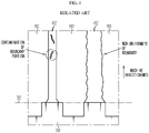
- FIG. 4 is a diagram showing a problem when a conventional shim plate is used.
- a defect caused by intermittently scattering the electrode active material slurry to a region outside a boundary, rather than stably forming the boundary between the electrode active material layer 60 and the uncoated portion 62 is illustrated.
- the electrode active material slurry scatters and is coated on the uncoated portion 62, contamination of a boundary portion occurs, or non-uniformity of a boundary such as a wave pattern occurs on the boundary.
- a coating boundary formed in an MD needs to be uniformly formed in order to avoid a slitting defect when slitting along the uncoated portion 62 later to form an electrode with each electrode active material layer 60, and to prevent possible occurrence of an electrode disconnection after a secondary battery is manufactured due to the contamination remaining in the uncoated portion 62.
- the present disclosure is designed to solve the problems of the related art, and therefore the present disclosure is directed to providing a slot die coater capable of uniformly forming a coating boundary formed in a machine direction (MD).
- MD machine direction
- a slot die coater including at least two die blocks; a shim plate provided between the two die blocks to form a slot; and a manifold provided in the die block and configured to accommodate a coating solution, wherein the coating solution is discharged and applied to a substrate through a discharge port communicatively connected with the slot, and wherein an end of the shim plate is moved backward relative to a die lip which is a front end of the die block such that the end of the shim plate is offset with respect to the die lip which is a front end of the die block.
- a size of the offset may be 50 ⁇ m to 2000 ⁇ m.
- the shim plate may include an open portion by cutting one region thereof so that a coating width of a coating layer applied on the substrate is determined.
- the shim plate may include a plurality of open portions by intermittently cutting one region thereof so that a coating width of a coating layer applied on the substrate is determined, and the coating layer of a stripe pattern shape may be formed on the substrate.
- a dual slot die coater including a lower die block; an intermediate die block disposed on an upper portion of the lower die block to form a lower slot therebetween; an upper die block disposed on an upper portion of the intermediate die block to form an upper slot therebetween; a lower shim plate configured to define the lower slot; and an upper shim plate configured to define the upper slot, wherein the lower die block, the intermediate die block, and the upper die block respectively comprise a lower die lip, an intermediate die lip and an upper die lip forming front ends thereof, a lower discharge port communicatively connected with the lower slot is formed between the lower die lip and the intermediate die lip, and an upper discharge port communicatively connected with the upper slot is formed between the intermediate die lip and the upper die lip, the dual slot die coater is configured to discharge and apply an electrode active material slurry to a surface of a continuously traveling substrate through at least one of the lower slot and the upper slot and form an electrode active material layer, and ends of the lower shim plate and the upper
- Each of the lower shim plate and the upper shim plate may include an open portion by cutting one region thereof so that a coating width of an electrode active material layer formed on the substrate is determined.
- Each of the lower shim plate and the upper shim plate may include a plurality of open portions by intermittently cutting one region thereof so that a coating width of an electrode active material layer formed on the substrate is determined, and the electrode active material layer of a stripe pattern shape is formed on the substrate.
- the lower shim plate and the upper shim plate may be aligned with each other in an up and down direction.
- the lower die block may include a first manifold accommodating a first electrode active material slurry and communicatively connected with the lower slot and the intermediate die block may include a second manifold accommodating a second electrode active material slurry and communicatively connected with the upper slot.
- the lower shim plate is interposed between the lower die block and the intermediate die block to adjust a width of the lower slot, and the upper shim plate is interposed between the intermediate die block and the upper die block to adjust a width of the upper slot.
- An offset size A of the upper shim plate and an offset size B of the lower shim plate may be the same.
- An offset size A of the upper shim plate may be different from an offset size B of the lower shim plate.
- the dual slot die coater may be configured to simultaneously discharge two types of electrode active material slurries through the upper slot and the lower slot to form an electrode active material layer of a double layer on the substrate, and when a coating gap G to a coating solution thickness D of the electrode active material slurries formed on the substrate is equal to or greater than 1.06, with respect to an offset size A of the upper shim plate and an offset size B of the lower shim plate, A:B may be set to 7:1 to 1:7.
- the end of the shim plate is moved backward relative to the die lip so as to be offset relative to the die lip. According to this configuration, even if a large pressure is applied to the coating solution discharged from the discharge port when the coating gap is small, after the coating solution is sufficiently expanded from the end of the shim plate in an offset section, that is, after a certain part of the discharge pressure is relieved, the coating solution may leave the die lip and reach the substrate so that the coating solution does not scatter. Accordingly, the boundary may be stably formed between the coating portion and the uncoated portion.
- the dual slot die coater optimized for application of the electrode active material slurry is provided.
- the end of the shim plate is also moved backward relative to the die lip so as to be offset relative to the die lip. According to this configuration, even if a large pressure is applied to the electrode active material slurry when the coating gap is small, the coating solution does not scatter. Accordingly, the boundary may be stably formed between the coating portion and the uncoated portion.
- the electrode active material layer having a stripe pattern shape it is possible to stably form the electrode active material layer without contamination of the boundary or non-uniformity of the boundary such as a wave pattern on the boundary.
- the dual slot die coater capable of simultaneously discharging two types of electrode active material slurries through the upper slot and the lower slot and forming the electrode active material layer of a double layer on the substrate is provided. It is possible to stably form a boundary between the electrode active material layer of a double layer and the uncoated portion. Accordingly, it is possible to obtain a coating product of uniform quality, particularly an electrode for a secondary battery.
- the coating gap relative to the thickness of the coating solution is equal to or greater than a predetermined value, with respect to the offset size A of the upper shim plate and the offset size B of the lower shim plate, even A:B is adjusted, and thus a pattern defect may be completely prevented.
- the slot die coater of the present disclosure it is possible to uniformly form the coating layer, particularly the electrode active material layer, with a desired thickness and shape, and preferably, it is possible to simultaneously coat two types of electrode active material slurries, and thus both performance and productivity are excellent.
- the slot die coater or the dual slot die coater of the present disclosure is an apparatus including a slot and coating a coating solution on a substrate through the slot. Since the dual slot die coater includes a lower slot and an upper slot, the dual slot die coater is an apparatus capable of coating a coating solution in a double layer.
- the 'substrate' described below is a current collector and the coating solution is an 'electrode active material slurry'.
- Both a first coating solution and a second coating solution are electrode active material slurries, and may mean electrode active material slurries that have the same or different composition (types of an active material, a conductive material, and a binder), content (an amount of each of the active material, the conductive material, and the binder), or physical properties.
- the dual slot die coater of the present disclosure is optimized for electrodes manufactured by applying at least two types of electrode active material slurries at the same time or by forming pattern coating while applying at least two types of electrode active material slurries in an alternating manner to form pattern coating.
- the scope of the present disclosure is not necessarily limited thereto.
- the substrate may be a porous scaffold constituting a separation membrane
- the first coating solution and the second coating solution may be organic matters having different compositions or physical properties. That is, when thin film coating is required, any substrate and any coating solution or any first coating solution and any second coating solution may be good.
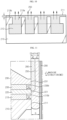
- FIG. 5 is a cross-sectional view of a slot die coater according to an embodiment of the present disclosure.
- FIG. 6 is a schematic exploded perspective view of the slot die coater according to an embodiment of the present disclosure.
- FIG. 7 shows an example of use of a shim plate in the slot die coater according to an embodiment of the present disclosure.
- the slot die coater 100 includes two die blocks 110 and 130.
- a shim plate 113 for forming a slot 101 is provided between the die blocks 110 and 130.
- the die blocks may be two or more.
- the slot die coater 100 is installed in a substantially horizontal direction (X direction) in which an electrode active material slurry which is a coating solution is discharged (approximately: ⁇ 5 degrees).
- X direction substantially horizontal direction
- the slot die coater 100 is not limited to the example form here.
- the slot die coater 100 may be configured as a vertical die in which a direction in which the coating solution is discharged upward (Y direction).
- the Z direction is a width direction of the slot die coater 100.
- the slot 101 is formed between where the die blocks 110 and 130 face each other.
- the shim plate 113 is provided between the die blocks 110 and 130 to provide a gap between the die blocks 110 and 130 so that the slot 101 corresponding to a passage through which the coating solution 150 may flow is formed.
- a thickness of the shim plate 113 determines a vertical width (Y direction and a slot gap) of the slot 10.
- the shim plate 113 may include a plurality of open portions 113a by intermittently cutting one region thereof and may be interposed in the remaining parts except for one side of an edge region of an opposite surface of each of the die blocks 110 and 130. Accordingly, a discharge port 101a through which the coating solution150 may be discharged to the outside is formed between a die lips 111 and 131, which are fore ends of the die blocks 110 and 130, respectively. The discharge port 101a may be formed when the die lips 111 and 131 are spaced apart from each other.
- the shim plate 113 functions as a gasket to prevent the coating solution 150 from leaking into the gap between the die blocks 110 and 130, except for a region where the discharge port 101a is formed, and thus the shim plate 113 is preferably made of a material having a sealing property.
- any one of the die blocks 110 and 130 includes a manifold 112 having a predetermined depth and communicatively connected with the slot 101.
- the manifold 112 is connected to a coating solution supply chamber (not shown) installed outside through a supply pipe to receive the coating solution 150.
- a coating solution supply chamber not shown
- the flow of the coating solution 150 is induced along the slot 101 and discharged to the outside through the discharge port 101a.
- a rotatably provided coating roll 180 is disposed in front of the slot die coater 100, the substrate 190 to be coated by rotating a coating roll 180 is driven, the coating solution 150 may be applied on the substrate 190 by discharging and continuously contacting the coating solution 150 with the surface of the substrate 190. Alternatively, supply and interruption of the coating solution 150 may be alternately performed so that pattern-coating may be intermittently performed on the substrate 190.
- the shim plate 113 determines a coating width of a coating layer applied on the substrate 190, and has a state of use as in FIG. 7 .
- the slot die coater 100 of FIG. 5 viewed in a down direction after the die block 130 thereon is removed is illustrated.
- the end 113b of the shim plate 113 is moved backward relative to the die lip 111 so as to be offset relative to the die lip 111. Since the die lips 111 and 131 are usually aligned in a straight line, the end 113b of the shim plate 113 is moved backward even relative to the die lip 131 which is not shown here.
- the shim plate 113 shown in FIG. 7 may include a plurality of open portions 113a by intermittently cutting one region thereof and form a coating layer 170 of a stripe pattern shape on the substrate 190.
- Reference numeral 172 denotes an uncoated portion on which a coating layer is not formed. If there is one open portion 113a, one coating layer 170 may be formed on the substrate 190.
- the size of an offset O of the shim plate may be 50 ⁇ m to 2000 ⁇ m.
- the size of the offset O is smaller than 50 ⁇ m, the effect of having the offset is insignificant.
- the size of the offset O is greater than 2000 ⁇ m, since it may cause non-uniformity of the boundary, the size needs not to exceed 2000 ⁇ m.
- the size of the offset O may be determined in consideration of the coating speed, the viscosity of the coating solution, the thickness of the coating solution, the coating gap, etc.
- the other conditions are the same and the coating speed is high, the size of the offset O needs to be increased.
- the other conditions are the same, and the viscosity of the coating solution increases, the size of the offset O needs to be increased.
- the other conditions are the same and the thickness of the coating solution is large, the size of the offset O needs to be increased.
- the other conditions are the same, and the coating gap is decreased, the size of the offset O needs to be increased.
- the end 113b of the shim plate 113 is moved backward relative to the die lips 111 and 131 so as to be offset relative to the die lip 111. According to this configuration, even if a large pressure is applied to the coating solution 150 when the coating gap is small, after the coating solution 150 is sufficiently expanded from the end 113b of the shim plate 113 in a section of the offset O, that is, the coating solution 150 may leave the die lips 111 and 131 and reach the substrate 190 so that the coating solution 150 does not scatter to other parts. Accordingly, the boundary may be stably formed between the coating portion and the uncoated portion.
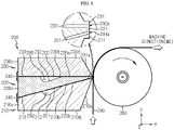
- FIG. 8 is a schematic cross-sectional view of a dual slot die coater according to another embodiment of the present disclosure.
- FIG. 9 is a schematic exploded perspective view of a dual slot die coater according to another embodiment of the present disclosure.
- FIG. 10 shows an example of use of a lower shim plate in a dual slot die coater according to another embodiment of the present disclosure.
- FIG. 11 is a side view of the dual slot die coater shown in FIG. 8 .
- a dual slot die coater 200 is an apparatus including a lower slot 201 and an upper slot 202, and capable of simultaneously or alternately applying the same or different two kinds of coating solutions on a substrate 290 through the lower slot 201 and the upper slot 202.
- the dual slot die coater 200 includes a lower die block 210, an intermediate die block 220 disposed on an upper portion of the lower die block 210, and an upper die block 230 disposed on an upper portion of the intermediate die block 220.
- the dual slot die coater 200 is installed in a substantially horizontal direction (X direction) in which an electrode active material slurry which is a coating solution is discharged (approximately: ⁇ 5 degrees).
- the intermediate die block 220 is a block located in the middle of blocks constituting the dual slot die coater 200, and is a block disposed between the lower die block 210 and the upper die block 230 to form a dual slot.
- a cross section of the intermediate die block 220 of the present embodiment is a right triangle, but is not necessarily limited to such as shape.
- the cross section may be provided as an isosceles triangle.
- a first surface 220a of the intermediate die block 220 facing the upper die block 230 lies almost horizontally, and a surface 230d (that is, a surface forming an upper surface of an outer circumferential surface of the dual slot die coater 200) opposite to a surface 230b of the upper die block 230 facing the first surface 220a also lies almost horizontally. In this way, the first surface 220a and the opposite surface 230d are almost parallel to each other.
- a surface 210d that is, a surface forming a lower surface of the outer circumferential surface of the dual slot die coater 200
- a surface 210b of the lower die block 210 facing the intermediate die block 220 also lies almost horizontally, and this surface is a bottom surface 210d (X-Z plane).
- a state in which the lower die block 210, the intermediate die block 220, and the upper die block 230 are combined has an approximately rectangular parallelepiped shape as a whole, and only a front portion from which the coating solution is discharged is inclined toward the substrate 290. This is advantageous in that a shape after assembly is approximately similar to that of a slot die coater including a single slot (e.g., 100 in FIG. 5 ) so that a slot die coater stand, etc. may be shared.
- the dual slot die coater 200 may further include two or more fixing units 240 provided on the rear surfaces 210c, 220c, and 230c thereof.
- the fixing units 240 are provided for fastening between the lower die block 210 and the intermediate die block 220 and for fastening between the intermediate die block 220 and the upper die block 230.
- a plurality of fixing units 240 may be provided in the width direction of the dual slot die coater 200. Bolts are fastened to the fixing units 240, through which the lower die block 210, the intermediate die block 220, and the upper die block 230 are assembled with each other.
- the lower die block 210, the intermediate die block 220, and the upper die block 230 are not necessarily limited to shapes of the above examples, and may be configured, for example, as vertical dies with the direction in which the coating solution is discharged as an upper direction and the rear surfaces 210c, 220c, and 230c as bottom surfaces.
- the lower die block 210 is a lowermost block among the blocks constituting the dual slot die coater 200, and the surface 210b facing the intermediate die block 220 has an inclined shape to form an angle of approximately 20 degrees to 60 degrees with respect to the bottom surface 210d.
- the lower slot 201 may be formed where the lower die block 210 and the intermediate die block 220 face each other.
- a lower shim plate 213 is interposed between the lower die block 210 and the intermediate die block 220 to provide a gap therebetween, so that the lower slot 201 corresponding to a passage through which the first coating solution 250 may flow may be formed. That is, the lower shim plate 213 defines the lower slot 201, and in this case, the thickness of the lower shim plate 213 determines the vertical width (Y-axis direction and a slot gap) of the lower slot 201.
- the lower shim plate 213 includes a plurality of open portions 213a by intermittently cutting one region thereof so that a coating width of the electrode active material layer formed on the substrate 290 is determined and may be interposed in the remaining portion except for one side in an edge region of an opposite surface of each of the lower die block 210 and the intermediate die block 220 as shown in FIGS. 9 and 10 . Accordingly, a lower discharge port 201a through which the first coating solution 250 may be discharged to the outside is formed only between a lower die lip 211 which is a front end portion of the lower die block 210 and the intermediate die lip 221 which is a front end portion of the intermediate die block 220.
- the lower discharge port 201a may be formed by making the lower die lip 211 and the intermediate die lip 221 spaced apart from each other.
- the lower shim plate 213 functions as a gasket to prevent the first coating solution 250 from leaking into a gap between the lower die block 210 and the intermediate die block 220 except for the region where the lower discharge port 201a is formed, and thus the lower shim plate 213 is preferably made of a material having sealing property.
- the lower die block 210 includes a first manifold 212 having a predetermined depth on the surface 210b facing the intermediate die block 220 and communicatively connected to the lower slot 201.
- the first manifold 212 is connected to a supply chamber (not shown) of the first coating solution 250 installed outside through a supply pipe to receive the first coating solution 250.
- the flow of the first coating solution 250 is induced along the lower slot 201 and discharged to the outside through the lower discharge port 201a.
- the first manifold 212 may be provided on a surface 220b of the intermediate die block 220 facing the lower die block 210.
- the upper die block 230 is disposed to face the first surface 220a which is an upper surface of the intermediate die block 220 that is horizontal with respect to a bottom surface.
- the upper slot 202 is thus formed where the intermediate die block 220 and the upper die block 230 face to each other.
- a second shim plate 233 may be interposed between the intermediate die block 220 and the upper die block 230 to provide a gap therebetween. Accordingly, the upper slot 202 corresponding to a passage through which a second coating solution 260 may flow is formed. In this case, a vertical width (Y-axis direction and a slot gap) of the upper slot 202 is determined by the second shim plate 233.
- the second shim plate 233 which also has a structure similar to that of the above-described first shim plate 213, includes a plurality of open portions 233a by intermittently cutting one region thereof, and may be interposed in the remaining portion except for one side in an edge region of an opposite surface of each of the intermediate die block 220 and the upper die block 230.
- a circumferential direction of the second shim plate 233 except for the front of the upper slot 202 is blocked, and the upper discharge port 202a is formed only between the front end portion of the intermediate die block 220 and a front end portion of the upper die block 230.
- the front end portion of the upper die block 230 is defined as the upper die lip 231.
- the upper discharge port 202a may be formed by making the intermediate die lip 221 and the upper die lip 231 spaced apart from each other.
- the upper shim plate 233 defines the upper slot 202.
- the intermediate die block 220 includes a second manifold 232 having a predetermined depth on the surface 220a facing the upper die block 230 and communicatively connected to the upper slot 202.
- the second manifold 232 is connected to a supply chamber of the second coating solution 260 installed outside through a supply pipe to receive the second coating solution 260.
- the second coating solution 260 is supplied from the outside along the supply pipe in the shape of a pipe and fully filled in the second manifold 232, the flow of the second coating solution 260 is induced along the upper slot 202 communicatively connected to the second manifold 232 and discharged to the outside through the upper discharge port 202a.
- the second manifold 232 may be provided on the surface 230b of the upper die block 230 facing the middle die block 220.
- the upper slot 202 and the lower slot 201 form a certain angle, and the angle may be approximately 20 degrees to 70 degrees.
- the upper slot 202 and the lower slot 201 may intersect each other at one point, and the upper discharge port 202a and the lower discharge port 201a may be provided near the intersection point. Accordingly, discharge points of the first coating solution 250 and the second coating solution 260 may be concentrated approximately at one point.
- a rotatably provided coating roll 280 is disposed in front of the dual slot die coater 200, the substrate 290 to be coated by rotating the coating roll 280 is driven, a coating solution such as the electrode active material slurry is extruded through at least one of the upper slot 202 and the lower slot 201 to form the electrode active material layer on the substrate 290.
- the lower shim plate 213 and the upper shim plate 233 determine the coating width of the electrode active material layer applied on the substrate 290, and have the same state of use as in FIG. 10 .
- the slot die coater 200 of FIG. 8 viewed in a down direction after the upper die block 230 and the intermediate die block 220 thereon are removed is illustrated.
- the end 213b of the lower shim plate 213 is moved backward relative to the lower die lip 211 so as to be offset relative to the lower die lip 211.
- the first coating solution 250 may be discharged from the first manifold 212 toward the substrate 290 through the open portion 213a of the lower shim plate 213. Since the lower die lip 211 and the intermediate die lip 221 are usually aligned in a straight line, the end 213b of the lower shim plate 213 is also moved backward relative to the intermediate die lip 221 which is not shown here.
- the size of the offset O may be 50 ⁇ m to 2000 ⁇ m.
- the example of use of the upper shim plate 233 is the same as that of the lower shim plate 213, and the end 233b of the upper shim plate 233 is also offset relative to the upper die lip 221 and the intermediate die lip 221.
- the size of the offset O of the upper shim plate 233 may also be 50 ⁇ m to 2000 ⁇ m.
- the lower shim plate 213 and the upper shim plate 233 are aligned with each other in the up and down direction (X direction) and left and right direction (Z direction), and thus may be used as shown in FIG. 11 .
- the rotatably provided coating roll 280 is disposed in front of the dual slot die coater 200, the substrate 290 to be coated by rotating the coating roll 280 is driven, and the first coating solution 250 and the second coating solution 260 are continuously contacted with the surface of the substrate 290 so that the substrate 290 may be coated in a double layer.
- supply and interruption of the first coating solution 250 and supply and interruption of the second coating solution 260 are alternately performed so that pattern-coating may be intermittently performed on the substrate 290.
- the offset size A of the upper shim plate 233 and the offset size B of the lower shim plate 213 may be the same or different.
- A>B, A ⁇ B, or A B.
- the coating gap G is preferably adjusted between a value 20% greater than and a value 20% smaller than the coating solution thickness D.
- the coating gap G relative to the coating solution thickness D is preferably set to have a value between 0.8 and 1.2.
- the coating gap G is much greater than the coating solution thickness D, fat-edge occurs in which the edge of the coating layer is thickly formed.
- the coating gap G is much smaller than the coating solution thickness D, since a large pressure is applied, a pattern defect occurs due to scattering of the coating solution, etc.
- the standard of 20% is determined in consideration of this point.
- the coating width is beyond a range adjustable by the coating gap G.
- A:B is preferably in the range of 7:1 to 1:7 when the coating gap G relative to the coating solution thickness D is equal to or greater than 1.06.
- the pattern defect is prevented by basically setting each of the offset size A of the upper shim plate 233 and the offset size B of the lower shim plate 213 within the range of 50 ⁇ m to 2000 ⁇ m. Furthermore, it is proposed that the ratio of the offset size A of the upper shim plate 233 to the offset size B of the lower shim plate 213 also needs to be considered when the coating gap G relative to the coating solution thickness D is greater than 1.06.
- each of the offset size A of the upper shim plate 233 and the offset size B of the lower shim plate 213 are set within the range of 50 ⁇ m to 2000 ⁇ m as a solution to relieve the pressure applied to the coating solution, but it should be noted that when the coating gap G relative to the coating solution thickness D is equal to or greater than a predetermined value, with respect to the offset size A of the upper shim plate 233 and the offset size B of the lower shim plate 213, even A:B is adjusted, and thus a pattern defect may be completely prevented.
- the dual slot die coater 200 is optimized for application of the electrode active material slurry for manufacturing a secondary battery.
- the thickness of the electrode active material layer which was about 130 ⁇ m gradually increased to reach 300 ⁇ m.
- the thick electrode active material layer is formed with the conventional slot die coater, since migration of a binder and a conductive material in the active material slurry deepens during drying, a final electrode is manufactured non-uniformly.
- a disadvantage is that it takes a long time.
- two types of electrode active material slurries may be simultaneously applied.
- the boundary may be stably formed between the coating portion and the uncoated portion.
- the electrode active material layer having a stripe pattern shape it is possible to stably form the electrode active material layer without contamination of the boundary or non-uniformity of the boundary such as a wave pattern on the boundary. This leads to no defect in the slitting along the uncoated portion. It is possible to reduce a discarded electrode plate, and thus the cost reduction effect is excellent.
- the electrode active material layer of a double layer is formed on the substrate 290 by simultaneously discharging two types of electrode active material slurries through the upper slot 202 and the lower slot 201, it is possible to stably form a boundary between the electrode active material layer of a double layer and the uncoated portion in both cases where different types of electrode active material slurries are used or the electrode active material layer is thickly coated by using the same electrode active material slurry. Accordingly, it is possible to obtain a coating product of uniform quality, particularly an electrode for a secondary battery.
- the dual slot die coater 200 of the present disclosure it is possible to uniformly form the coating layer, particularly the electrode active material layer, with a desired thickness and shape, and preferably, it is possible to simultaneously coat two types of electrode active material slurries, and thus both performance and productivity are excellent.
- the case of applying the coating solution in two layers or the case of performing pattern-coating by alternately supplying the coating solution has been described as an example, but it will be understood without separate explanation that it is also applied to the case where three or more layers are simultaneously applied by providing three or more slots.
- the effect of preventing the electrode active material slurry from scattering by relieving the pressure of the electrode active material slurry by the shim plate offset structure is excellent. This has the effect of forming a stable boundary, securing coating processability, and securing reproducibility.
- Comparative Examples 1 to 4 are cases where the offset is 0 when the end of the shim plate is aligned with the die lip.
- Embodiments 1 to 5 are cases where the end of the shim plate is moved backward from the die lip so that the shim plate has the offset of 50 ⁇ m to 2000 ⁇ m.
- Comparative Example 5 is case where the offset is 2500 ⁇ m which exceeds the preferred offset range proposed in the present disclosure.
- the coating speed was all set to 50 m/min.
- the viscosity of the electrode active material slurry which is the coating solution was all 4000 cps.
- the thickness of the coating solution was 100 ⁇ m as a target. Cases where the coating gap is 90 ⁇ m, 105 ⁇ m, 115 ⁇ m, and 125 ⁇ m were experimented.
- the shim plate offset is 50 ⁇ m to 2000 ⁇ m, thereby forming the electrode active material layer having no contamination of the boundary portion, a uniform boundary and no other defects.
- the coating gap is 90 ⁇ m which is smaller than 100 ⁇ m which is the coating solution thickness, it should be paid to the remarkable effect of forming a stable boundary even when more pressure is applied to the electrode active material slurry.
- the total thickness of the coating solution which is the sum of the coating solution thickness of the upper layer by the second coating solution 260 and the coating solution thickness of the lower layer by the first coating solution 250, is 160 ⁇ m as a target. Cases where the coating gap is 150 ⁇ m, 170 ⁇ m, 180 ⁇ m, and 190 ⁇ m were experimented.
- Comparative Examples 6 to 8 and 12 are cases where the offset is all 0 when the ends of the upper shim plate and the lower shim plate are aligned with the die lip.
- Comparative Examples 9 and 13 are cases where the offset is 2500 ⁇ m which exceeds the preferred offset range proposed by the present disclosure.
- Embodiments 6 to 15 are cases where the ends of the upper shim plate and the lower shim plate are moved backward from the die lip so that the upper shim plate and the lower shim plate have the offset of 50 ⁇ m to 2000 ⁇ m.
- Comparative Examples 10 and 11 are cases where the offset size A of the upper shim plate and the offset size B of the lower shim plate are within the range proposed in the present disclosure, but the coating gap to the coating solution thickness is 1.06 and A: B is beyond the range proposed in the present disclosure. At this time, the non-uniformity of the boundary has been observed.
- the offset size A of the upper shim plate and the offset size B of the lower shim plate are adjusted within 50 ⁇ m to 2000 ⁇ m, thereby forming the electrode active material layer having no contamination of the boundary portion, a uniform boundary and no other defects.
- A:B is set to 7:1 to 1:7, thereby forming the electrode active material layer having no contamination of the boundary portion, a uniform boundary and no other defects.
- slot die coater 101 slot 101a: discharge port 110, 130: die block 111, 131: die lip 112: manifold 113: shim plate 113a: open portion 113b: end O: offset 150: coating solution 170: coating layer 172: uncoated portion 180, 280: coating roll 190, 290: substrate 200: dual slot die coater 201: lower slot 201a: lower discharge port 202: upper slot 202a: upper discharge port 210: lower die block 211: lower die lip 212: first manifold 213: lower shim plate 220: intermediate die block 221: intermediate die lip 230: upper die block 231: upper die lip 232: second manifold 233: upper shim plate 240: fixing unit 250: first coating solution 260: second coating solution
Landscapes
- Engineering & Computer Science (AREA)
- Chemical & Material Sciences (AREA)
- Manufacturing & Machinery (AREA)
- Chemical Kinetics & Catalysis (AREA)
- Electrochemistry (AREA)
- General Chemical & Material Sciences (AREA)
- Materials Engineering (AREA)
- Battery Electrode And Active Subsutance (AREA)
- Coating Apparatus (AREA)
Abstract
Description
- The present disclosure relates to a slot die coater, and more particularly to a slot die coater capable of uniformly forming a coating boundary formed in a machine direction (MD). The present application claims priority to
Korean Patent Application No. 10-2020-0141477 filed on October 28, 2020 - As technology development and demand for mobile devices increase, the demand for secondary batteries as an energy source is rapidly increasing, and such secondary batteries essentially include an electrode assembly which is a power generation element. The electrode assembly has a form in which a positive electrode, a separator, and a negative electrode are stacked at least once, and the positive electrode and the negative electrode are prepared by applying and drying a positive electrode active material slurry and a negative electrode active material slurry on a current collector made of aluminum foil and copper foil, respectively. In order to equalize charging/discharging features of secondary batteries, the positive electrode active material slurry and the negative electrode active material slurry should be uniformly coated on the current collector, and a slot die coater is conventionally used.
-
FIG. 1 shows an example of a coating method using a conventional slot die coater.FIG. 2 is a cross-sectional view of the slot die coater taken along II-II' ofFIG. 1 along a machine direction (MD) (a traveling direction of a current collector). - Referring to
FIGS. 1 and2 , in an electrode manufacturing method using aslot die coater 30, an electrode active material slurry discharged from theslot die coater 30 is applied on ancurrent collector 20 transferred by acoating roll 10. The electrode active material slurry discharged from theslot die coater 30 is widely applied on one surface of thecurrent collector 20 to form an electrode active material layer. Theslot die coater 30 includes two dieblocks slot 36 between the two dieblocks manifold 38, and discharged through adischarge port 40 communicatively connected to theslot 36, thereby forming the electrode active material layer.Reference numerals 42 and 44 denote die lips which are front ends of the dieblocks - A coating width of the electrode active material layer coated on the
current collector 20 is determined according to a width of theslot 36. When it is necessary to change the coating width, various coating widths may be implemented by changing ashim plate 50 that determines an inner space of themanifold 38 and the width of theslot 36. In this regard,FIGS. 3A to 3C schematically show examples of adjusting the coating width by varying the size and shape of theshim plate 50 inserted between thedie blocks - Referring to
FIG. 3A , theshim plate 50 includes anopen portion 50a by cutting one region thereof and is interposed in the remaining parts except for one side of an edge region of an opposite surface of each of thedie blocks open portion 50a of theshim plate 50 is designed such that an electrodeactive material layer 60 having a coating width a is formed on thecurrent collector 20, anduncoated portions 62 are formed on both sides of the electrodeactive material layer 60. - Referring to
FIG. 3B , in order to form the electrodeactive material layer 60 having a coating width b smaller than a on thecurrent collector 20, the width of theopen portion 50a of theshim plate 50 is designed as b. - If necessary, the electrode
active material layer 60 having a stripe pattern shape may be formed on thecurrent collector 20. In such a case, theshim plate 50 as shown inFIG. 3C is used. Referring toFIG. 3C , a region of theshim plate 50 is intermittently cut so that theshim plate 50 includes a plurality ofopen portions 50a, and the width of theopen portion 50a is c smaller than a or b. When such ashim plate 50 is used, the electrodeactive material layer 60 having the coating width c is formed on thecurrent collector 20 in a plurality of stripe pattern shapes as many as the number of theopen portions 50a, and theuncoated portions 62 are formed on both sides of the electrodeactive material layer 60. - It should be noted that, in
FIGS. 3A to 3C , adie lip 42 and the end of theshim plate 50 are aligned. For various reasons, when a coating gap, that is, a distance between thedischarge port 40 of theslot die coater 30 and the current collector 20 (or a distance between thedie lips 42 and 44 and the current collector 20) is small, in particular, when the coating gap is smaller than a coating thickness, a large pressure is applied to the discharged electrode active material slurry due to the small coating gap. For this reason, the following problems frequently occur when the electrodeactive material layer 60 having the stripe pattern shape as shown inFIG. 3C is formed. -
FIG. 4 is a diagram showing a problem when a conventional shim plate is used. Referring toFIG. 4 , as a result of applying a large pressure to a discharged electrode active material slurry, a defect caused by intermittently scattering the electrode active material slurry to a region outside a boundary, rather than stably forming the boundary between the electrodeactive material layer 60 and theuncoated portion 62, is illustrated. As the electrode active material slurry scatters and is coated on theuncoated portion 62, contamination of a boundary portion occurs, or non-uniformity of a boundary such as a wave pattern occurs on the boundary. A coating boundary formed in an MD needs to be uniformly formed in order to avoid a slitting defect when slitting along theuncoated portion 62 later to form an electrode with each electrodeactive material layer 60, and to prevent possible occurrence of an electrode disconnection after a secondary battery is manufactured due to the contamination remaining in theuncoated portion 62. - The present disclosure is designed to solve the problems of the related art, and therefore the present disclosure is directed to providing a slot die coater capable of uniformly forming a coating boundary formed in a machine direction (MD).
- These and other objects and advantages of the present disclosure may be understood from the following detailed description and will become more fully apparent from the exemplary embodiments of the present disclosure. Also, it will be easily understood that the objects and advantages of the present disclosure may be realized by the means shown in the appended claims and combinations thereof.
- In one aspect of the present disclosure, there is provided a slot die coater including at least two die blocks; a shim plate provided between the two die blocks to form a slot; and a manifold provided in the die block and configured to accommodate a coating solution, wherein the coating solution is discharged and applied to a substrate through a discharge port communicatively connected with the slot, and wherein an end of the shim plate is moved backward relative to a die lip which is a front end of the die block such that the end of the shim plate is offset with respect to the die lip which is a front end of the die block.
- A size of the offset may be 50 µm to 2000 µm.
- The shim plate may include an open portion by cutting one region thereof so that a coating width of a coating layer applied on the substrate is determined.
- The shim plate may include a plurality of open portions by intermittently cutting one region thereof so that a coating width of a coating layer applied on the substrate is determined, and the coating layer of a stripe pattern shape may be formed on the substrate.
- In another aspect of the present disclosure, there is provided a dual slot die coater including a lower die block; an intermediate die block disposed on an upper portion of the lower die block to form a lower slot therebetween; an upper die block disposed on an upper portion of the intermediate die block to form an upper slot therebetween; a lower shim plate configured to define the lower slot; and an upper shim plate configured to define the upper slot, wherein the lower die block, the intermediate die block, and the upper die block respectively comprise a lower die lip, an intermediate die lip and an upper die lip forming front ends thereof, a lower discharge port communicatively connected with the lower slot is formed between the lower die lip and the intermediate die lip, and an upper discharge port communicatively connected with the upper slot is formed between the intermediate die lip and the upper die lip, the dual slot die coater is configured to discharge and apply an electrode active material slurry to a surface of a continuously traveling substrate through at least one of the lower slot and the upper slot and form an electrode active material layer, and ends of the lower shim plate and the upper shim plate are moved backward relative to the lower die lip, the intermediate die lip and the upper die lip so as to be offset relative to the lower die lip, the intermediate die lip and the upper die lip.
- Each of the lower shim plate and the upper shim plate may include an open portion by cutting one region thereof so that a coating width of an electrode active material layer formed on the substrate is determined.
- Each of the lower shim plate and the upper shim plate may include a plurality of open portions by intermittently cutting one region thereof so that a coating width of an electrode active material layer formed on the substrate is determined, and the electrode active material layer of a stripe pattern shape is formed on the substrate.
- The lower shim plate and the upper shim plate may be aligned with each other in an up and down direction.
- The lower die block may include a first manifold accommodating a first electrode active material slurry and communicatively connected with the lower slot and the intermediate die block may include a second manifold accommodating a second electrode active material slurry and communicatively connected with the upper slot.
The lower shim plate is interposed between the lower die block and the intermediate die block to adjust a width of the lower slot, and the upper shim plate is interposed between the intermediate die block and the upper die block to adjust a width of the upper slot. - An offset size A of the upper shim plate and an offset size B of the lower shim plate may be the same.
- An offset size A of the upper shim plate may be different from an offset size B of the lower shim plate.
- The dual slot die coater may be configured to simultaneously discharge two types of electrode active material slurries through the upper slot and the lower slot to form an electrode active material layer of a double layer on the substrate, and when a coating gap G to a coating solution thickness D of the electrode active material slurries formed on the substrate is equal to or greater than 1.06, with respect to an offset size A of the upper shim plate and an offset size B of the lower shim plate, A:B may be set to 7:1 to 1:7.
- According to an aspect of the present disclosure, the end of the shim plate is moved backward relative to the die lip so as to be offset relative to the die lip. According to this configuration, even if a large pressure is applied to the coating solution discharged from the discharge port when the coating gap is small, after the coating solution is sufficiently expanded from the end of the shim plate in an offset section, that is, after a certain part of the discharge pressure is relieved, the coating solution may leave the die lip and reach the substrate so that the coating solution does not scatter. Accordingly, the boundary may be stably formed between the coating portion and the uncoated portion.
- According to another aspect of the present disclosure, the dual slot die coater optimized for application of the electrode active material slurry is provided. The end of the shim plate is also moved backward relative to the die lip so as to be offset relative to the die lip. According to this configuration, even if a large pressure is applied to the electrode active material slurry when the coating gap is small, the coating solution does not scatter. Accordingly, the boundary may be stably formed between the coating portion and the uncoated portion. In particular, when the electrode active material layer having a stripe pattern shape is formed, it is possible to stably form the electrode active material layer without contamination of the boundary or non-uniformity of the boundary such as a wave pattern on the boundary.
- According to another aspect of the present disclosure, the dual slot die coater capable of simultaneously discharging two types of electrode active material slurries through the upper slot and the lower slot and forming the electrode active material layer of a double layer on the substrate is provided. It is possible to stably form a boundary between the electrode active material layer of a double layer and the uncoated portion. Accordingly, it is possible to obtain a coating product of uniform quality, particularly an electrode for a secondary battery.
- According to another aspect of the present disclosure, when the coating gap relative to the thickness of the coating solution is equal to or greater than a predetermined value, with respect to the offset size A of the upper shim plate and the offset size B of the lower shim plate, even A:B is adjusted, and thus a pattern defect may be completely prevented.
- When the slot die coater of the present disclosure is used, it is possible to uniformly form the coating layer, particularly the electrode active material layer, with a desired thickness and shape, and preferably, it is possible to simultaneously coat two types of electrode active material slurries, and thus both performance and productivity are excellent.
- The accompanying drawings illustrate a preferred embodiment of the present disclosure and together with the foregoing disclosure, serve to provide further understanding of the technical features of the present disclosure, and thus, the present disclosure is not construed as being limited to the drawing.
-
FIG. 1 is a schematic diagram showing an example of using a slot die coater according to the conventional art. -
FIG. 2 is a cross-sectional view taken along II-II' ofFIG. 1 . -
FIGS. 3A to 3C show various examples of using a conventional slot die coater. -
FIG. 4 is a diagram showing a problem when a conventional shim plate is used. -
FIG. 5 is a cross-sectional view of a slot die coater according to an embodiment of the present disclosure. -
FIG. 6 is a schematic exploded perspective view of a slot die coater according to an embodiment of the present disclosure. -
FIG. 7 shows an example of use of a shim plate in a slot die coater according to an embodiment of the present disclosure. -
FIG. 8 is a schematic cross-sectional view of a dual slot die coater according to another embodiment of the present disclosure. -
FIG. 9 is a schematic exploded perspective view of a dual slot die coater according to another embodiment of the present disclosure. -
FIG. 10 shows an example of use of a lower shim plate in a dual slot die coater according to another embodiment of the present disclosure. -
FIG. 11 is a side view of the dual slot die coater shown inFIG. 8 . - Hereinafter, preferred embodiments of the present disclosure will be described in detail with reference to the accompanying drawings. Prior to the description, it should be understood that the terms used in the specification and the appended claims should not be construed as limited to general and dictionary meanings, but interpreted based on the meanings and concepts corresponding to technical aspects of the present disclosure on the basis of the principle that the inventor is allowed to define terms appropriately for the best explanation. Therefore, the description proposed herein is just a preferable example for the purpose of illustrations only, not intended to limit the scope of the disclosure, so it should be understood that other equivalents and modifications could be made thereto without departing from the scope of the disclosure.
- The slot die coater or the dual slot die coater of the present disclosure is an apparatus including a slot and coating a coating solution on a substrate through the slot. Since the dual slot die coater includes a lower slot and an upper slot, the dual slot die coater is an apparatus capable of coating a coating solution in a double layer. The 'substrate' described below is a current collector and the coating solution is an 'electrode active material slurry'. Both a first coating solution and a second coating solution are electrode active material slurries, and may mean electrode active material slurries that have the same or different composition (types of an active material, a conductive material, and a binder), content (an amount of each of the active material, the conductive material, and the binder), or physical properties. In particular, the dual slot die coater of the present disclosure is optimized for electrodes manufactured by applying at least two types of electrode active material slurries at the same time or by forming pattern coating while applying at least two types of electrode active material slurries in an alternating manner to form pattern coating. However, the scope of the present disclosure is not necessarily limited thereto. For example, the substrate may be a porous scaffold constituting a separation membrane, and the first coating solution and the second coating solution may be organic matters having different compositions or physical properties. That is, when thin film coating is required, any substrate and any coating solution or any first coating solution and any second coating solution may be good.
-
FIG. 5 is a cross-sectional view of a slot die coater according to an embodiment of the present disclosure.FIG. 6 is a schematic exploded perspective view of the slot die coater according to an embodiment of the present disclosure.FIG. 7 shows an example of use of a shim plate in the slot die coater according to an embodiment of the present disclosure. - Referring to
FIGS. 5 to 7 , theslot die coater 100 includes twodie blocks shim plate 113 for forming aslot 101 is provided between the die blocks 110 and 130. The die blocks may be two or more. - In
FIG. 5 , theslot die coater 100 is installed in a substantially horizontal direction (X direction) in which an electrode active material slurry which is a coating solution is discharged (approximately: ± 5 degrees). However, theslot die coater 100 is not limited to the example form here. For example, theslot die coater 100 may be configured as a vertical die in which a direction in which the coating solution is discharged upward (Y direction). The Z direction is a width direction of theslot die coater 100. - The
slot 101 is formed between where the die blocks 110 and 130 face each other. Theshim plate 113 is provided between the die blocks 110 and 130 to provide a gap between the die blocks 110 and 130 so that theslot 101 corresponding to a passage through which thecoating solution 150 may flow is formed. A thickness of theshim plate 113 determines a vertical width (Y direction and a slot gap) of theslot 10. - As shown in
FIG. 6 , theshim plate 113 may include a plurality ofopen portions 113a by intermittently cutting one region thereof and may be interposed in the remaining parts except for one side of an edge region of an opposite surface of each of the die blocks 110 and 130. Accordingly, adischarge port 101a through which the coating solution150 may be discharged to the outside is formed between adie lips discharge port 101a may be formed when thedie lips - For reference, the
shim plate 113 functions as a gasket to prevent thecoating solution 150 from leaking into the gap between the die blocks 110 and 130, except for a region where thedischarge port 101a is formed, and thus theshim plate 113 is preferably made of a material having a sealing property. - Any one of the die blocks 110 and 130 includes a manifold 112 having a predetermined depth and communicatively connected with the
slot 101. Although not shown, the manifold 112 is connected to a coating solution supply chamber (not shown) installed outside through a supply pipe to receive thecoating solution 150. When thecoating solution 150 is fully filled in the manifold 112, the flow of thecoating solution 150 is induced along theslot 101 and discharged to the outside through thedischarge port 101a. - According to the
slot die coater 100 having such a configuration, a rotatably providedcoating roll 180 is disposed in front of theslot die coater 100, thesubstrate 190 to be coated by rotating acoating roll 180 is driven, thecoating solution 150 may be applied on thesubstrate 190 by discharging and continuously contacting thecoating solution 150 with the surface of thesubstrate 190. Alternatively, supply and interruption of thecoating solution 150 may be alternately performed so that pattern-coating may be intermittently performed on thesubstrate 190. - Here, the
shim plate 113 determines a coating width of a coating layer applied on thesubstrate 190, and has a state of use as inFIG. 7 . - Referring to
FIG. 7 , theslot die coater 100 ofFIG. 5 viewed in a down direction after thedie block 130 thereon is removed is illustrated. Theend 113b of theshim plate 113 is moved backward relative to thedie lip 111 so as to be offset relative to thedie lip 111. Since thedie lips end 113b of theshim plate 113 is moved backward even relative to thedie lip 131 which is not shown here. - In particular, the
shim plate 113 shown inFIG. 7 may include a plurality ofopen portions 113a by intermittently cutting one region thereof and form acoating layer 170 of a stripe pattern shape on thesubstrate 190.Reference numeral 172 denotes an uncoated portion on which a coating layer is not formed. If there is oneopen portion 113a, onecoating layer 170 may be formed on thesubstrate 190. - Preferably, the size of an offset O of the shim plate may be 50µm to 2000µm. When the size of the offset O is smaller than 50 µm, the effect of having the offset is insignificant. When the size of the offset O is greater than 2000 µm, since it may cause non-uniformity of the boundary, the size needs not to exceed 2000 µm. The size of the offset O may be determined in consideration of the coating speed, the viscosity of the coating solution, the thickness of the coating solution, the coating gap, etc. When the other conditions are the same and the coating speed is high, the size of the offset O needs to be increased. When the other conditions are the same, and the viscosity of the coating solution increases, the size of the offset O needs to be increased. When the other conditions are the same and the thickness of the coating solution is large, the size of the offset O needs to be increased. When the other conditions are the same, and the coating gap is decreased, the size of the offset O needs to be increased.
- As such, in the
slot die coater 100 of the present disclosure, theend 113b of theshim plate 113 is moved backward relative to the dielips die lip 111. According to this configuration, even if a large pressure is applied to thecoating solution 150 when the coating gap is small, after thecoating solution 150 is sufficiently expanded from theend 113b of theshim plate 113 in a section of the offset O, that is, thecoating solution 150 may leave thedie lips substrate 190 so that thecoating solution 150 does not scatter to other parts. Accordingly, the boundary may be stably formed between the coating portion and the uncoated portion. -
FIG. 8 is a schematic cross-sectional view of a dual slot die coater according to another embodiment of the present disclosure.FIG. 9 is a schematic exploded perspective view of a dual slot die coater according to another embodiment of the present disclosure.FIG. 10 shows an example of use of a lower shim plate in a dual slot die coater according to another embodiment of the present disclosure.FIG. 11 is a side view of the dual slot die coater shown inFIG. 8 . - A dual
slot die coater 200 according to the present disclosure is an apparatus including alower slot 201 and anupper slot 202, and capable of simultaneously or alternately applying the same or different two kinds of coating solutions on asubstrate 290 through thelower slot 201 and theupper slot 202. - Referring to
FIGS. 8 and9 , the dualslot die coater 200 includes alower die block 210, anintermediate die block 220 disposed on an upper portion of thelower die block 210, and anupper die block 230 disposed on an upper portion of theintermediate die block 220. - In
FIG. 8 , the dualslot die coater 200 is installed in a substantially horizontal direction (X direction) in which an electrode active material slurry which is a coating solution is discharged (approximately: ±5 degrees). - The
intermediate die block 220 is a block located in the middle of blocks constituting the dualslot die coater 200, and is a block disposed between thelower die block 210 and theupper die block 230 to form a dual slot. A cross section of theintermediate die block 220 of the present embodiment is a right triangle, but is not necessarily limited to such as shape. For example, the cross section may be provided as an isosceles triangle. - A
first surface 220a of theintermediate die block 220 facing theupper die block 230 lies almost horizontally, and asurface 230d (that is, a surface forming an upper surface of an outer circumferential surface of the dual slot die coater 200) opposite to asurface 230b of theupper die block 230 facing thefirst surface 220a also lies almost horizontally. In this way, thefirst surface 220a and theopposite surface 230d are almost parallel to each other. And asurface 210d (that is, a surface forming a lower surface of the outer circumferential surface of the dual slot die coater 200) opposite to a surface 210b of thelower die block 210 facing theintermediate die block 220 also lies almost horizontally, and this surface is abottom surface 210d (X-Z plane). - Surfaces of the
lower die block 210, theintermediate die block 220, and theupper die block 230 which are opposite to a direction in which the electrode active material slurry is discharged, that is,rear surfaces slot die coater 200 in thelower die block 210 and theupper die block 230 which are the outermost die blocks, thebottom surface 210d of thelower die block 210 and theupper surface 230d of theupper die block 230 manufactured to be almost vertical to therear surfaces first surface 220a of theintermediate die block 220 manufactured to be almost vertical to therear surface 220c may be used. In such die blocks 210, 220, and 230, since edges formed by surfaces are formed at right angles, there is a right angle portion in the cross section, and since a vertical or horizontal surface may be used as a reference surface, manufacturing or handling of the die blocks 210, 220, and 230 are easy and the precision thereof is guaranteed. In addition, a state in which thelower die block 210, theintermediate die block 220, and theupper die block 230 are combined has an approximately rectangular parallelepiped shape as a whole, and only a front portion from which the coating solution is discharged is inclined toward thesubstrate 290. This is advantageous in that a shape after assembly is approximately similar to that of a slot die coater including a single slot (e.g., 100 inFIG. 5 ) so that a slot die coater stand, etc. may be shared. - The dual
slot die coater 200 may further include two ormore fixing units 240 provided on therear surfaces units 240 are provided for fastening between thelower die block 210 and theintermediate die block 220 and for fastening between theintermediate die block 220 and theupper die block 230. A plurality of fixingunits 240 may be provided in the width direction of the dualslot die coater 200. Bolts are fastened to the fixingunits 240, through which thelower die block 210, theintermediate die block 220, and theupper die block 230 are assembled with each other. - The
lower die block 210, theintermediate die block 220, and theupper die block 230 are not necessarily limited to shapes of the above examples, and may be configured, for example, as vertical dies with the direction in which the coating solution is discharged as an upper direction and therear surfaces - The
lower die block 210 is a lowermost block among the blocks constituting the dualslot die coater 200, and the surface 210b facing theintermediate die block 220 has an inclined shape to form an angle of approximately 20 degrees to 60 degrees with respect to thebottom surface 210d. - The
lower slot 201 may be formed where thelower die block 210 and theintermediate die block 220 face each other. For example, alower shim plate 213 is interposed between thelower die block 210 and theintermediate die block 220 to provide a gap therebetween, so that thelower slot 201 corresponding to a passage through which thefirst coating solution 250 may flow may be formed. That is, thelower shim plate 213 defines thelower slot 201, and in this case, the thickness of thelower shim plate 213 determines the vertical width (Y-axis direction and a slot gap) of thelower slot 201. - The
lower shim plate 213 includes a plurality ofopen portions 213a by intermittently cutting one region thereof so that a coating width of the electrode active material layer formed on thesubstrate 290 is determined and may be interposed in the remaining portion except for one side in an edge region of an opposite surface of each of thelower die block 210 and theintermediate die block 220 as shown inFIGS. 9 and10 . Accordingly, alower discharge port 201a through which thefirst coating solution 250 may be discharged to the outside is formed only between alower die lip 211 which is a front end portion of thelower die block 210 and theintermediate die lip 221 which is a front end portion of theintermediate die block 220. Thelower discharge port 201a may be formed by making thelower die lip 211 and theintermediate die lip 221 spaced apart from each other. - For reference, the
lower shim plate 213 functions as a gasket to prevent thefirst coating solution 250 from leaking into a gap between thelower die block 210 and theintermediate die block 220 except for the region where thelower discharge port 201a is formed, and thus thelower shim plate 213 is preferably made of a material having sealing property. - The
lower die block 210 includes afirst manifold 212 having a predetermined depth on the surface 210b facing theintermediate die block 220 and communicatively connected to thelower slot 201. Although not shown in the drawings, thefirst manifold 212 is connected to a supply chamber (not shown) of thefirst coating solution 250 installed outside through a supply pipe to receive thefirst coating solution 250. When thefirst coating solution 250 is fully filled in thefirst manifold 212, the flow of thefirst coating solution 250 is induced along thelower slot 201 and discharged to the outside through thelower discharge port 201a. - As another example, the
first manifold 212 may be provided on asurface 220b of theintermediate die block 220 facing thelower die block 210. - The
upper die block 230 is disposed to face thefirst surface 220a which is an upper surface of theintermediate die block 220 that is horizontal with respect to a bottom surface. Theupper slot 202 is thus formed where theintermediate die block 220 and theupper die block 230 face to each other. - Like the
lower slot 201 described above, asecond shim plate 233 may be interposed between theintermediate die block 220 and theupper die block 230 to provide a gap therebetween. Accordingly, theupper slot 202 corresponding to a passage through which asecond coating solution 260 may flow is formed. In this case, a vertical width (Y-axis direction and a slot gap) of theupper slot 202 is determined by thesecond shim plate 233. - In addition, the
second shim plate 233, which also has a structure similar to that of the above-describedfirst shim plate 213, includes a plurality ofopen portions 233a by intermittently cutting one region thereof, and may be interposed in the remaining portion except for one side in an edge region of an opposite surface of each of theintermediate die block 220 and theupper die block 230. Similarly, a circumferential direction of thesecond shim plate 233 except for the front of theupper slot 202 is blocked, and theupper discharge port 202a is formed only between the front end portion of theintermediate die block 220 and a front end portion of theupper die block 230. The front end portion of theupper die block 230 is defined as theupper die lip 231. In other words, theupper discharge port 202a may be formed by making theintermediate die lip 221 and theupper die lip 231 spaced apart from each other. As such, theupper shim plate 233 defines theupper slot 202. - In addition, the
intermediate die block 220 includes asecond manifold 232 having a predetermined depth on thesurface 220a facing theupper die block 230 and communicatively connected to theupper slot 202. Although not shown in the drawings, thesecond manifold 232 is connected to a supply chamber of thesecond coating solution 260 installed outside through a supply pipe to receive thesecond coating solution 260. When thesecond coating solution 260 is supplied from the outside along the supply pipe in the shape of a pipe and fully filled in thesecond manifold 232, the flow of thesecond coating solution 260 is induced along theupper slot 202 communicatively connected to thesecond manifold 232 and discharged to the outside through theupper discharge port 202a. - As another example, the
second manifold 232 may be provided on thesurface 230b of theupper die block 230 facing themiddle die block 220. - The
upper slot 202 and thelower slot 201 form a certain angle, and the angle may be approximately 20 degrees to 70 degrees. Theupper slot 202 and thelower slot 201 may intersect each other at one point, and theupper discharge port 202a and thelower discharge port 201a may be provided near the intersection point. Accordingly, discharge points of thefirst coating solution 250 and thesecond coating solution 260 may be concentrated approximately at one point. - In the dual
slot die coater 200, a rotatably providedcoating roll 280 is disposed in front of the dualslot die coater 200, thesubstrate 290 to be coated by rotating thecoating roll 280 is driven, a coating solution such as the electrode active material slurry is extruded through at least one of theupper slot 202 and thelower slot 201 to form the electrode active material layer on thesubstrate 290. - Here, the
lower shim plate 213 and theupper shim plate 233 determine the coating width of the electrode active material layer applied on thesubstrate 290, and have the same state of use as inFIG. 10 . - Referring to
FIG. 10 , theslot die coater 200 ofFIG. 8 viewed in a down direction after theupper die block 230 and theintermediate die block 220 thereon are removed is illustrated. Theend 213b of thelower shim plate 213 is moved backward relative to thelower die lip 211 so as to be offset relative to thelower die lip 211. Thefirst coating solution 250 may be discharged from thefirst manifold 212 toward thesubstrate 290 through theopen portion 213a of thelower shim plate 213. Since thelower die lip 211 and theintermediate die lip 221 are usually aligned in a straight line, theend 213b of thelower shim plate 213 is also moved backward relative to theintermediate die lip 221 which is not shown here. - The size of the offset O may be 50 µm to 2000 µm.
- The example of use of the
upper shim plate 233 is the same as that of thelower shim plate 213, and theend 233b of theupper shim plate 233 is also offset relative to theupper die lip 221 and theintermediate die lip 221. The size of the offset O of theupper shim plate 233 may also be 50 µm to 2000 µm. - The
lower shim plate 213 and theupper shim plate 233 are aligned with each other in the up and down direction (X direction) and left and right direction (Z direction), and thus may be used as shown inFIG. 11 . According to the dualslot die coater 200 having the configuration described above with further reference toFIG. 11 , the rotatably providedcoating roll 280 is disposed in front of the dualslot die coater 200, thesubstrate 290 to be coated by rotating thecoating roll 280 is driven, and thefirst coating solution 250 and thesecond coating solution 260 are continuously contacted with the surface of thesubstrate 290 so that thesubstrate 290 may be coated in a double layer. Alternatively, supply and interruption of thefirst coating solution 250 and supply and interruption of thesecond coating solution 260 are alternately performed so that pattern-coating may be intermittently performed on thesubstrate 290. - Here, the offset size A of the
upper shim plate 233 and the offset size B of thelower shim plate 213 may be the same or different. For example, A>B, A<B, or A=B. - When the
first coating solution 250 and thesecond coating solution 260 are continuously contacted with the surface of thesubstrate 290 so that thesubstrate 290 is coated in the double layer as shown, in the relationship between the total coating solution thickness D which is the sum of the first coating solution thickness d1 and the second coating solution thickness d2 formed on thesubstrate 290 and the coating gap G , which is a distance between thedischarge ports slot die coater 200 and thesubstrate 290 or a distance between thedie lips substrate 290, the coating gap G is preferably adjusted between avalue 20% greater than and avalue 20% smaller than the coating solution thickness D. In other words, the coating gap G relative to the coating solution thickness D is preferably set to have a value between 0.8 and 1.2. When the coating gap G is much greater than the coating solution thickness D, fat-edge occurs in which the edge of the coating layer is thickly formed. When the coating gap G is much smaller than the coating solution thickness D, since a large pressure is applied, a pattern defect occurs due to scattering of the coating solution, etc. The standard of 20% is determined in consideration of this point. - In particular, when the coating gap G is equal to or greater than a predetermined value compared to the coating solution thickness D, the coating width is beyond a range adjustable by the coating gap G. The present inventors have found that with respect to the offset size A of the
upper shim plate 233 and the offset size B of thelower shim plate 213, A:B is preferably in the range of 7:1 to 1:7 when the coating gap G relative to the coating solution thickness D is equal to or greater than 1.06. When the coating gap G relative to the coating solution thickness D is equal to or greater than 1.06, if A:B is beyond the above range, a pattern defect occurs. - In the present disclosure, the pattern defect is prevented by basically setting each of the offset size A of the
upper shim plate 233 and the offset size B of thelower shim plate 213 within the range of 50 µm to 2000 µm. Furthermore, it is proposed that the ratio of the offset size A of theupper shim plate 233 to the offset size B of thelower shim plate 213 also needs to be considered when the coating gap G relative to the coating solution thickness D is greater than 1.06. - When the coating gap G relative to the coating solution thickness D is smaller than a predetermined value, it is sufficient to set each of the offset size A of the
upper shim plate 233 and the offset size B of thelower shim plate 213 within the range of 50 µm to 2000 µm as a solution to relieve the pressure applied to the coating solution, but it should be noted that when the coating gap G relative to the coating solution thickness D is equal to or greater than a predetermined value, with respect to the offset size A of theupper shim plate 233 and the offset size B of thelower shim plate 213, even A:B is adjusted, and thus a pattern defect may be completely prevented. - The dual
slot die coater 200 is optimized for application of the electrode active material slurry for manufacturing a secondary battery. In order to manufacture a secondary battery of high energy density, the thickness of the electrode active material layer which was about 130 µm gradually increased to reach 300 µm. When the thick electrode active material layer is formed with the conventional slot die coater, since migration of a binder and a conductive material in the active material slurry deepens during drying, a final electrode is manufactured non-uniformly. In order to solve this problem, when coating is performed two times such as applying thinly and drying the electrode active material layer and then applying and drying the electrode active material layer, a disadvantage is that it takes a long time. In order to simultaneously improve electrode performance and productivity, when the dualslot die coater 200 is used, two types of electrode active material slurries may be simultaneously applied. - And, according to the offset configuration of the
lower shim plate 213 and theupper shim plate 233 as proposed in the present disclosure, even if a large pressure is applied to the electrode active material slurry when the coating gap is small, the coating solution does not scatter. Accordingly, the boundary may be stably formed between the coating portion and the uncoated portion. In particular, when the electrode active material layer having a stripe pattern shape is formed, it is possible to stably form the electrode active material layer without contamination of the boundary or non-uniformity of the boundary such as a wave pattern on the boundary. This leads to no defect in the slitting along the uncoated portion. It is possible to reduce a discarded electrode plate, and thus the cost reduction effect is excellent. In addition, in the case where the coating gap is relatively large, under the condition that it is difficult to adjust the coating width, with respect to the offset size A of theupper shim plate 233 and the offset size B of thelower shim plate 213, even A:B is adjusted, and thus a double layer is stably formed without scattering the electrode active material slurry. - According to the present disclosure, when the electrode active material layer of a double layer is formed on the
substrate 290 by simultaneously discharging two types of electrode active material slurries through theupper slot 202 and thelower slot 201, it is possible to stably form a boundary between the electrode active material layer of a double layer and the uncoated portion in both cases where different types of electrode active material slurries are used or the electrode active material layer is thickly coated by using the same electrode active material slurry. Accordingly, it is possible to obtain a coating product of uniform quality, particularly an electrode for a secondary battery. - When the dual
slot die coater 200 of the present disclosure is used, it is possible to uniformly form the coating layer, particularly the electrode active material layer, with a desired thickness and shape, and preferably, it is possible to simultaneously coat two types of electrode active material slurries, and thus both performance and productivity are excellent. - Meanwhile, in the present embodiment, the case of applying the coating solution in two layers or the case of performing pattern-coating by alternately supplying the coating solution has been described as an example, but it will be understood without separate explanation that it is also applied to the case where three or more layers are simultaneously applied by providing three or more slots.
- As described above, according to the present disclosure, even if the discharge pressure of the electrode active material slurry increases, the effect of preventing the electrode active material slurry from scattering by relieving the pressure of the electrode active material slurry by the shim plate offset structure is excellent. This has the effect of forming a stable boundary, securing coating processability, and securing reproducibility.
- Hereinafter, comparative examples and embodiments will be described in order to explain the effect of the shim plate offset as proposed in the present disclosure. First, with respect to Comparative Examples 1 to 5 and Embodiments 1 to 5 in the slot die coater including one slot as described with reference to
FIG. 5 , etc., the experimental conditions and results are summarized in Table 1.[Table 1] Coating speed (m/min) Viscosity (cps) Coating solution thickness (µm) Coating gap (µm) Shim plate offset (µm) Contamination of boundary portion Non-uniformity of boundary Other defects Comparative example 1 50 4000 100 105 0 O X Fat-Edge Comparative example 2 50 4000 100 115 0 X X Fat-Edge Comparative example 3 50 4000 100 125 0 X X Fat-Edge Comparative example 4 50 4000 100 90 0 O X X Embodiment 1 50 4000 100 90 50 X X X Embodiment 2 50 4000 100 90 200 X X X Embodiment 3 50 4000 100 105 500 X X X Embodiment 4 50 4000 100 105 1000 X X X Embodiment 5 50 4000 100 105 2000 X X X Comparative example 5 50 4000 100 105 2500 X O O - Comparative Examples 1 to 4 are cases where the offset is 0 when the end of the shim plate is aligned with the die lip. Embodiments 1 to 5 are cases where the end of the shim plate is moved backward from the die lip so that the shim plate has the offset of 50 µm to 2000 µm. Comparative Example 5 is case where the offset is 2500 µm which exceeds the preferred offset range proposed in the present disclosure.
- The coating speed was all set to 50 m/min. The viscosity of the electrode active material slurry which is the coating solution was all 4000 cps. The thickness of the coating solution was 100 µm as a target. Cases where the coating gap is 90 µm, 105 µm, 115 µm, and 125 µm were experimented.
- As a result of the experiment, in all the embodiments of the present disclosure in which the shim plate offset is present, contamination of the boundary portion has not occurred. When the coating gap is 115 µm and 125 µm as in Comparative Examples 2 and 3 in which the shim plate offset is 0, contamination of the boundary portion has not occurred, but other defects such as fat-edge has occurred. In Comparative Example 1 in which the coating gap is reduced to 105 µm, not only other defects but also contamination of the boundary portion has occurred. In particular, in Comparative Example 4, in which more pressure is applied to the electrode active material slurry because the coating gap is 90 µm which is smaller than 100 µm which is the coating solution thickness, the contamination of the boundary portion was severe. Therefore, when there is no shim plate offset as in Comparative Examples 1 to 3, other defects occur, and when the coating gap is reduced as in Comparative Examples 1 and 4, contamination of the boundary portion occurs.
- The non-uniformity of the boundary has occurred in Comparative Example 5 in which the shim plate offset is 2500 µm. Therefore, the offset should not be too large.
- As described above, according to an embodiment of the present disclosure, the shim plate offset is 50 µm to 2000 µm, thereby forming the electrode active material layer having no contamination of the boundary portion, a uniform boundary and no other defects. In particular, as in Embodiments 1 and 2, since the coating gap is 90 µm which is smaller than 100 µm which is the coating solution thickness, it should be paid to the remarkable effect of forming a stable boundary even when more pressure is applied to the electrode active material slurry.
- Next, Comparative Examples 6 to 13 and Embodiments 6 to 15 in the dual slot die coater including two slots as described with reference to
FIG. 8 , etc. will be described. - The experimental conditions and results are summarized in Table 2.
[Table 2] Coating solution thickness (µm) Coating gap (µm) Coating gap relative to coating solution thickness Shim plate offset (µm) A:B Contamination of boundary portion Non-uniformity of boundary Other defects upper layer lower layer upper layer (A) lower layer (B) Comparative example 6 80 80 170 1.06 0 0 O X Fat-Edge Comparative example 7 80 80 180 1.13 0 0 X X Fat-Edge Comparative example 8 80 80 190 1.19 0 0 X X Fat-Edge Embodiment 6 80 80 170 1.06 50 50 1:1 X X X Embodiment 7 80 80 170 1.06 500 500 1:1 X X X Embodiment 8 80 80 170 1.06 1000 1000 1:1 X X X Embodiment 9 80 80 170 1.06 2000 2000 1:1 X X X Comparative example 9 80 80 170 1.06 2500 2500 1:1 X O O Embodiment 10 80 80 170 1.06 300 100 3:1 X X X Embodiment 11 80 80 170 1.06 650 100 6.5:1 X X X Comparative example 10 80 80 170 1.06 800 100 8:1 X O X Embodiment 12 80 80 170 1.06 100 650 1:6.5 X X X Comparative example 11 80 80 170 1.06 100 800 1:8 X O X Comparative example 12 80 80 150 0.94 0 0 O X X Embodiment 13 80 80 150 0.94 50 50 1:1 X X X Embodiment 14 80 80 150 0.94 200 200 1:1 X X X Embodiment 15 80 80 150 0.94 2000 2000 1:1 X X X Comparative example 13 80 80 150 0.94 2500 2500 1:1 X O O - The total thickness of the coating solution which is the sum of the coating solution thickness of the upper layer by the
second coating solution 260 and the coating solution thickness of the lower layer by thefirst coating solution 250, is 160 µm as a target. Cases where the coating gap is 150 µm, 170 µm, 180 µm, and 190 µm were experimented. - Comparative Examples 6 to 8 and 12 are cases where the offset is all 0 when the ends of the upper shim plate and the lower shim plate are aligned with the die lip. Comparative Examples 9 and 13 are cases where the offset is 2500 µm which exceeds the preferred offset range proposed by the present disclosure. Embodiments 6 to 15 are cases where the ends of the upper shim plate and the lower shim plate are moved backward from the die lip so that the upper shim plate and the lower shim plate have the offset of 50 µm to 2000 µm.
- As a result of the experiment, in all the embodiments of the present disclosure in which the shim plate offset is present, contamination of the boundary portion has not occurred. There was no non-uniformity of the boundary. In Comparative Examples 6 to 8 and 12 in which the shim plate offset is 0, contamination of the boundary portion or fat-edge has occurred. In Comparative Examples 9 and 13 in which the shim plate offset is 2500 µm, non-uniformity of the boundary and other defects have occurred.
- In particular, it is noticeable that Comparative Examples 10 and 11 are cases where the offset size A of the upper shim plate and the offset size B of the lower shim plate are within the range proposed in the present disclosure, but the coating gap to the coating solution thickness is 1.06 and A: B is beyond the range proposed in the present disclosure. At this time, the non-uniformity of the boundary has been observed.
- As described above, according to an embodiment of the present disclosure, the offset size A of the upper shim plate and the offset size B of the lower shim plate are adjusted within 50 µm to 2000 µm, thereby forming the electrode active material layer having no contamination of the boundary portion, a uniform boundary and no other defects. In particular, as in Embodiments 6 to 12, when the coating gap is greater than the coating solution thickness, and the coating gap to the coating solution thickness is equal to or greater than 1.06, A:B is set to 7:1 to 1:7, thereby forming the electrode active material layer having no contamination of the boundary portion, a uniform boundary and no other defects.
- The present disclosure has been described in detail. However, it should be understood that the detailed description and specific examples, while indicating preferred embodiments of the disclosure, are given by way of illustration only, since various changes and modifications within the scope of the disclosure will become apparent to those skilled in the art from this detailed description.
- Meanwhile, although terms indicating directions such as up, down, left, and right are used in the present specification, these terms are only for convenience of description, and it is apparent to those skilled in the art that these terms may vary depending on a position of a target object or a position of an observer.
-
100: slot die coater 101: slot 101a: discharge port 110, 130: die block 111, 131: die lip 112: manifold 113: shim plate 113a: open portion 113b: end O: offset 150: coating solution 170: coating layer 172: uncoated portion 180, 280: coating roll 190, 290: substrate 200: dual slot die coater 201: lower slot 201a: lower discharge port 202: upper slot 202a: upper discharge port 210: lower die block 211: lower die lip 212: first manifold 213: lower shim plate 220: intermediate die block 221: intermediate die lip 230: upper die block 231: upper die lip 232: second manifold 233: upper shim plate 240: fixing unit 250: first coating solution 260: second coating solution
Claims (13)
- A slot die coater comprising:at least two die blocks;a shim plate provided between the two die blocks to form a slot; anda manifold provided in the die block and accommodating a coating solution,wherein the coating solution is discharged and applied to a substrate through a discharge port communicatively connected with the slot,wherein an end of the shim plate is moved backward relative to a die lip which is a front end of the die block such that the end of the shim plate is offset with respect to the die lip which is a front end of the die block.
- The slot die coater of claim 1, wherein a size of the offset is 50 µm to 2000 µm.
- The slot die coater of claim 1, wherein the shim plate comprises an open portion by cutting one region thereof such that a coating width of a coating layer applied on the substrate is determined.
- The slot die coater of claim 1, wherein the shim plate comprises a plurality of open portions by intermittently cutting one region thereof such that a coating width of a coating layer applied on the substrate is determined, and the coating layer of a stripe pattern shape is formed on the substrate.
- A dual slot die coater comprising:a lower die block;an intermediate die block disposed on an upper portion of the lower die block to form a lower slot therebetween;an upper die block disposed on an upper portion of the intermediate die block to form an upper slot therebetween;a lower shim plate configured to define the lower slot; andan upper shim plate configured to define the upper slot,wherein the lower die block, the intermediate die block, and the upper die block respectively comprise a lower die lip, an intermediate die lip, and an upper die lip forming front ends thereof, a lower discharge port communicatively connected with the lower slot is formed between the lower die lip and the intermediate die lip, and an upper discharge port communicatively connected with the upper slot is formed between the intermediate die lip and the upper die lip,wherein the dual slot die coater is configured to discharge and apply an electrode active material slurry to a surface of a continuously traveling substrate through at least one of the lower slot and the upper slot and form an electrode active material layer, andwherein ends of the lower shim plate and the upper shim plate are moved backward relative to the lower die lip, the intermediate die lip, and the upper die lip so as to be offset relative to the lower die lip, the intermediate die lip, and the upper die lip.
- The dual slot die coater of claim 5, wherein a size of the offset is 50 µm to 2000 µm.
- The dual slot die coater of claim 5, wherein each of the lower shim plate and the upper shim plate comprises an open portion by cutting one region thereof such that a coating width of an electrode active material layer formed on the substrate is determined.
- The dual slot die coater of claim 5, wherein each of the lower shim plate and the upper shim plate comprises a plurality of open portions by intermittently cutting one region thereof such that a coating width of an electrode active material layer formed on the substrate is determined, and the electrode active material layer of a stripe pattern shape is formed on the substrate.
- The dual slot die coater of claim 8, wherein the lower shim plate and the upper shim plate are aligned with each other in an up and down direction.
- The dual slot die coater of claim 5, wherein the lower die block comprises a first manifold accommodating a first electrode active material slurry and communicatively connected with the lower slot and the intermediate die block comprises a second manifold accommodating a second electrode active material slurry and communicatively connected with the upper slot.
- The dual slot die coater of claim 5, wherein an offset size A of the upper shim plate and an offset size B of the lower shim plate are the same.
- The dual slot die coater of claim 5, wherein an offset size A of the upper shim plate is different from an offset size B of the lower shim plate.
- The dual slot die coater of claim 5, wherein the dual slot die coater is configured to simultaneously discharge two types of electrode active material slurries through the upper slot and the lower slot to form an electrode active material layer of a double layer on the substrate, and
wherein when a coating gap to a coating solution thickness of the electrode active material slurries formed on the substrate is equal to or greater than 1.06, with respect to an offset size A of the upper shim plate and an offset size B of the lower shim plate, A:B is set to 7:1 to 1:7.
Applications Claiming Priority (2)
| Application Number | Priority Date | Filing Date | Title |
|---|---|---|---|
| KR20200141477 | 2020-10-28 | ||
| PCT/KR2021/015260 WO2022092826A1 (en) | 2020-10-28 | 2021-10-27 | Slot die coater |
Publications (2)
| Publication Number | Publication Date |
|---|---|
| EP4154994A1 true EP4154994A1 (en) | 2023-03-29 |
| EP4154994A4 EP4154994A4 (en) | 2024-01-31 |
Family
ID=81382855
Family Applications (1)
| Application Number | Title | Priority Date | Filing Date |
|---|---|---|---|
| EP21886820.6A Pending EP4154994A4 (en) | 2020-10-28 | 2021-10-27 | Slot die coater |
Country Status (5)
| Country | Link |
|---|---|
| US (1) | US20230140800A1 (en) |
| EP (1) | EP4154994A4 (en) |
| KR (1) | KR20220056816A (en) |
| CN (1) | CN115379906B (en) |
| WO (1) | WO2022092826A1 (en) |
Families Citing this family (2)
| Publication number | Priority date | Publication date | Assignee | Title |
|---|---|---|---|---|
| JP7593741B2 (en) | 2020-03-26 | 2024-12-03 | ノードソン コーポレーション | Nozzle, adhesive application head, adhesive application device, and diaper manufacturing method |
| KR20220059744A (en) * | 2020-11-03 | 2022-05-10 | 주식회사 엘지에너지솔루션 | Shim for die coater, die coater including the same, and lithium secondary battery including a positive electrode manufactured using the same |
Family Cites Families (22)
| Publication number | Priority date | Publication date | Assignee | Title |
|---|---|---|---|---|
| WO1996024088A1 (en) * | 1995-02-02 | 1996-08-08 | Minnesota Mining And Manufacturing Company | Method and apparatus for applying thin fluid coating stripes |
| DE19530516A1 (en) * | 1995-08-19 | 1997-02-20 | Hoechst Ag | Device for applying a coating solution |
| AU2875500A (en) * | 1999-02-26 | 2000-09-14 | Procter & Gamble Company, The | Process for extruding a continuous layer |
| US6423140B1 (en) * | 2000-06-08 | 2002-07-23 | Formosa Advanced Coating Technologies, Inc. | Die set for preparing ABCABC multiple-stripe coating |
| US20060060135A1 (en) * | 2004-09-17 | 2006-03-23 | Eastman Kodak Company | Apparatus for forming discontinuous stripe coatings |
| US8074902B2 (en) * | 2008-04-14 | 2011-12-13 | Nordson Corporation | Nozzle and method for dispensing random pattern of adhesive filaments |
| JP2010051845A (en) * | 2008-08-26 | 2010-03-11 | Nitto Denko Corp | Method for coating resinous coating liquid, and slot die coater |
| US8752501B2 (en) * | 2010-07-29 | 2014-06-17 | Corning Incorporated | Systems and methods for dispensing a fluid |
| KR101750326B1 (en) * | 2012-12-07 | 2017-06-23 | 주식회사 엘지화학 | Improved slot die for chamber structure and coating apparatus having the same |
| JP6212951B2 (en) * | 2013-05-22 | 2017-10-18 | 凸版印刷株式会社 | Method for producing battery electrode member |
| JP6877877B2 (en) * | 2016-01-26 | 2021-05-26 | ノードソン コーポレーションNordson Corporation | nozzle |
| CN110198792B (en) * | 2017-02-03 | 2021-10-26 | 日本汽车能源株式会社 | Coating die, coating device, coating method, and method for manufacturing secondary battery |
| US10675654B2 (en) * | 2017-03-01 | 2020-06-09 | Nordson Corporation | Multi-layer slot die system and method |
| KR102248306B1 (en) * | 2017-07-13 | 2021-05-03 | 주식회사 엘지화학 | Coating Apparatus |
| KR102190114B1 (en) * | 2017-08-17 | 2020-12-11 | 주식회사 엘지화학 | Slot Die Coater Changing Coating Formation of Electrode Active Material Slurry by Movement of Slots |
| EP3476495A1 (en) * | 2017-10-26 | 2019-05-01 | RAMPF Holding GmbH & Co. KG | Slot die, coating arrangement comprising such a slot die, and cleaning device for such a slot die |
| WO2019109101A1 (en) * | 2017-12-01 | 2019-06-06 | Georgia Tech Research Corporation | Device and method for scaling and coating of continuous multi-material stripes and patterns |
| DK180562B1 (en) | 2019-01-31 | 2021-06-28 | Motional Ad Llc | Merging data from multiple lidar devices |
| JP7255052B2 (en) * | 2019-02-15 | 2023-04-11 | 株式会社ヒラノテクシード | Coating equipment |
| KR102866099B1 (en) * | 2019-11-20 | 2025-09-26 | 삼성에스디아이 주식회사 | Rechargeable battery electrode manufacturing slot die |
| JP7646400B2 (en) * | 2021-03-15 | 2025-03-17 | 株式会社東芝 | Coating Head |
| TWI849925B (en) * | 2023-05-23 | 2024-07-21 | 輝能科技股份有限公司 | Slot die coating apparatus and the coating method thereof |
-
2021
- 2021-10-27 US US17/918,261 patent/US20230140800A1/en active Pending
- 2021-10-27 WO PCT/KR2021/015260 patent/WO2022092826A1/en not_active Ceased
- 2021-10-27 EP EP21886820.6A patent/EP4154994A4/en active Pending
- 2021-10-27 CN CN202180027401.4A patent/CN115379906B/en active Active
- 2021-10-27 KR KR1020210145036A patent/KR20220056816A/en active Pending
Also Published As
| Publication number | Publication date |
|---|---|
| CN115379906B (en) | 2024-08-06 |
| KR20220056816A (en) | 2022-05-06 |
| US20230140800A1 (en) | 2023-05-04 |
| WO2022092826A1 (en) | 2022-05-05 |
| CN115379906A (en) | 2022-11-22 |
| EP4154994A4 (en) | 2024-01-31 |
Similar Documents
| Publication | Publication Date | Title |
|---|---|---|
| EP4151320A1 (en) | Slot die coater | |
| CN115461163B (en) | Double slot die coater | |
| EP4104938B1 (en) | Multiple slot die coater | |
| EP4147792B1 (en) | Slot die coater with improved coating solution flow | |
| US12539524B2 (en) | Multi-slot die coater | |
| EP4134168A1 (en) | Multiple slot die coater | |
| EP4134169B1 (en) | Multi-slot die coater | |
| EP4154994A1 (en) | Slot die coater | |
| EP4169623B1 (en) | Method of coating a current collector with a slot die coater having improved coating solution flow | |
| KR20220043030A (en) | Multiple slot die coater | |
| US20230219112A1 (en) | Dual Slot Die Coater Including Air Vent | |
| EP4154991A1 (en) | Multi-slot die coater with improved manifolds | |
| EP4596113A1 (en) | Slot die coater and method for manufacturing electrode plate of secondary battery by using same | |
| KR20220016782A (en) | Multiple slot die coater | |
| KR20220016781A (en) | Multiple slot die coater | |
| KR20220052719A (en) | Dual slot die coater | |
| KR20220023245A (en) | Dual slot die coater |
Legal Events
| Date | Code | Title | Description |
|---|---|---|---|
| STAA | Information on the status of an ep patent application or granted ep patent |
Free format text: STATUS: THE INTERNATIONAL PUBLICATION HAS BEEN MADE |
|
| PUAI | Public reference made under article 153(3) epc to a published international application that has entered the european phase |
Free format text: ORIGINAL CODE: 0009012 |
|
| STAA | Information on the status of an ep patent application or granted ep patent |
Free format text: STATUS: REQUEST FOR EXAMINATION WAS MADE |
|
| 17P | Request for examination filed |
Effective date: 20221220 |
|
| AK | Designated contracting states |
Kind code of ref document: A1 Designated state(s): AL AT BE BG CH CY CZ DE DK EE ES FI FR GB GR HR HU IE IS IT LI LT LU LV MC MK MT NL NO PL PT RO RS SE SI SK SM TR |
|
| A4 | Supplementary search report drawn up and despatched |
Effective date: 20240105 |
|
| RIC1 | Information provided on ipc code assigned before grant |
Ipc: H01M 4/04 20060101ALI20231222BHEP Ipc: B05C 5/02 20060101AFI20231222BHEP |
|
| DAV | Request for validation of the european patent (deleted) | ||
| DAX | Request for extension of the european patent (deleted) |