EP4154761A1 - Head for a personal care device - Google Patents
Head for a personal care device Download PDFInfo
- Publication number
- EP4154761A1 EP4154761A1 EP21199135.1A EP21199135A EP4154761A1 EP 4154761 A1 EP4154761 A1 EP 4154761A1 EP 21199135 A EP21199135 A EP 21199135A EP 4154761 A1 EP4154761 A1 EP 4154761A1
- Authority
- EP
- European Patent Office
- Prior art keywords
- cleaning element
- carrier
- embedded
- head
- cavity
- Prior art date
- Legal status (The legal status is an assumption and is not a legal conclusion. Google has not performed a legal analysis and makes no representation as to the accuracy of the status listed.)
- Granted
Links
Images


Classifications
-
- A—HUMAN NECESSITIES
- A46—BRUSHWARE
- A46B—BRUSHES
- A46B1/00—Brush bodies and bristles moulded as a unit
-
- A—HUMAN NECESSITIES
- A46—BRUSHWARE
- A46B—BRUSHES
- A46B3/00—Brushes characterised by the way in which the bristles are fixed or joined in or on the brush body or carrier
- A46B3/22—Brushes characterised by the way in which the bristles are fixed or joined in or on the brush body or carrier rubber bristles being fixed in or on brush bodies
-
- A—HUMAN NECESSITIES
- A46—BRUSHWARE
- A46B—BRUSHES
- A46B13/00—Brushes with driven brush bodies or carriers
- A46B13/02—Brushes with driven brush bodies or carriers power-driven carriers
-
- A—HUMAN NECESSITIES
- A46—BRUSHWARE
- A46B—BRUSHES
- A46B7/00—Bristle carriers arranged in the brush body
- A46B7/04—Bristle carriers arranged in the brush body interchangeably removable bristle carriers
-
- A—HUMAN NECESSITIES
- A46—BRUSHWARE
- A46B—BRUSHES
- A46B9/00—Arrangements of the bristles in the brush body
- A46B9/02—Position or arrangement of bristles in relation to surface of the brush body, e.g. inclined, in rows, in groups
- A46B9/04—Arranged like in or for toothbrushes
-
- A—HUMAN NECESSITIES
- A46—BRUSHWARE
- A46D—MANUFACTURE OF BRUSHES
- A46D1/00—Bristles; Selection of materials for bristles
- A46D1/02—Bristles details
- A46D1/0207—Bristles characterised by the choice of material, e.g. metal
-
- A—HUMAN NECESSITIES
- A46—BRUSHWARE
- A46D—MANUFACTURE OF BRUSHES
- A46D1/00—Bristles; Selection of materials for bristles
- A46D1/02—Bristles details
- A46D1/0238—Bristles with non-round cross-section
-
- A—HUMAN NECESSITIES
- A46—BRUSHWARE
- A46D—MANUFACTURE OF BRUSHES
- A46D1/00—Bristles; Selection of materials for bristles
- A46D1/02—Bristles details
- A46D1/0284—Bristles having rounded ends
-
- A—HUMAN NECESSITIES
- A61—MEDICAL OR VETERINARY SCIENCE; HYGIENE
- A61C—DENTISTRY; APPARATUS OR METHODS FOR ORAL OR DENTAL HYGIENE
- A61C17/00—Devices for cleaning, polishing, rinsing or drying teeth, teeth cavities or prostheses; Saliva removers; Dental appliances for receiving spittle
- A61C17/16—Power-driven cleaning or polishing devices
- A61C17/22—Power-driven cleaning or polishing devices with brushes, cushions, cups, or the like
- A61C17/222—Brush body details, e.g. the shape thereof or connection to handle
-
- B—PERFORMING OPERATIONS; TRANSPORTING
- B29—WORKING OF PLASTICS; WORKING OF SUBSTANCES IN A PLASTIC STATE IN GENERAL
- B29C—SHAPING OR JOINING OF PLASTICS; SHAPING OF MATERIAL IN A PLASTIC STATE, NOT OTHERWISE PROVIDED FOR; AFTER-TREATMENT OF THE SHAPED PRODUCTS, e.g. REPAIRING
- B29C45/00—Injection moulding, i.e. forcing the required volume of moulding material through a nozzle into a closed mould; Apparatus therefor
- B29C45/0001—Injection moulding, i.e. forcing the required volume of moulding material through a nozzle into a closed mould; Apparatus therefor characterised by the choice of material
-
- B—PERFORMING OPERATIONS; TRANSPORTING
- B29—WORKING OF PLASTICS; WORKING OF SUBSTANCES IN A PLASTIC STATE IN GENERAL
- B29C—SHAPING OR JOINING OF PLASTICS; SHAPING OF MATERIAL IN A PLASTIC STATE, NOT OTHERWISE PROVIDED FOR; AFTER-TREATMENT OF THE SHAPED PRODUCTS, e.g. REPAIRING
- B29C45/00—Injection moulding, i.e. forcing the required volume of moulding material through a nozzle into a closed mould; Apparatus therefor
- B29C45/16—Making multilayered or multicoloured articles
-
- A—HUMAN NECESSITIES
- A46—BRUSHWARE
- A46B—BRUSHES
- A46B2200/00—Brushes characterized by their functions, uses or applications
- A46B2200/10—For human or animal care
- A46B2200/1066—Toothbrush for cleaning the teeth or dentures
-
- A—HUMAN NECESSITIES
- A46—BRUSHWARE
- A46B—BRUSHES
- A46B3/00—Brushes characterised by the way in which the bristles are fixed or joined in or on the brush body or carrier
- A46B3/04—Brushes characterised by the way in which the bristles are fixed or joined in or on the brush body or carrier by mouldable materials, e.g. metals, cellulose derivatives, plastics
-
- B—PERFORMING OPERATIONS; TRANSPORTING
- B29—WORKING OF PLASTICS; WORKING OF SUBSTANCES IN A PLASTIC STATE IN GENERAL
- B29C—SHAPING OR JOINING OF PLASTICS; SHAPING OF MATERIAL IN A PLASTIC STATE, NOT OTHERWISE PROVIDED FOR; AFTER-TREATMENT OF THE SHAPED PRODUCTS, e.g. REPAIRING
- B29C45/00—Injection moulding, i.e. forcing the required volume of moulding material through a nozzle into a closed mould; Apparatus therefor
- B29C45/16—Making multilayered or multicoloured articles
- B29C2045/1681—Making multilayered or multicoloured articles one layer penetrating at one or more areas through another layer
-
- B—PERFORMING OPERATIONS; TRANSPORTING
- B29—WORKING OF PLASTICS; WORKING OF SUBSTANCES IN A PLASTIC STATE IN GENERAL
- B29K—INDEXING SCHEME ASSOCIATED WITH SUBCLASSES B29B, B29C OR B29D, RELATING TO MOULDING MATERIALS OR TO MATERIALS FOR MOULDS, REINFORCEMENTS, FILLERS OR PREFORMED PARTS, e.g. INSERTS
- B29K2021/00—Use of unspecified rubbers as moulding material
- B29K2021/003—Thermoplastic elastomers
-
- B—PERFORMING OPERATIONS; TRANSPORTING
- B29—WORKING OF PLASTICS; WORKING OF SUBSTANCES IN A PLASTIC STATE IN GENERAL
- B29L—INDEXING SCHEME ASSOCIATED WITH SUBCLASS B29C, RELATING TO PARTICULAR ARTICLES
- B29L2031/00—Other particular articles
- B29L2031/42—Brushes
- B29L2031/425—Toothbrush
Definitions
- the present disclosure is concerned with a head for a personal care device, which head comprises a carrier and at least one cleaning element.
- a head for a personal care device comprises a carrier having a front surface, at least one cleaning element partly embedded in the carrier and thus having an embedded cleaning element portion and a non-embedded cleaning element portion, the non-embedded cleaning element portion extending from the front surface of the carrier between a base end on the front surface and a free end and the embedded cleaning element portion extending from the front surface between a top end on the front surface and a bottom end, wherein the base end of the non-embedded cleaning element portion has a base end cross-sectional shape and a base end cross-sectional area, and the top end of the embedded cleaning element portion has a top end cross-sectional shape that is different to the base end cross-sectional shape and a top end cross-sectional area that is larger than the base end cross-sectional area.
- a method for making a head for a personal care device comprises the steps of
- personal care shall mean the nurture (or care) of the skin and of its adnexa (i.e., hairs and nails) and of the teeth and the oral cavity (including the tongue, the gums etc.), where the aim is on the one hand the prevention of illnesses and the maintenance and strengthening of health and on the other hand the cosmetic treatment and improvement of the appearance of the skin and its adnexa. It shall include the maintenance and strengthening of wellbeing. This includes skin care, hair care, and oral care as well as nail care. This further includes grooming activities such as beard care, shaving, and depilation.
- a "personal care device” thus means any device for performing such nurturing or grooming activity, e.g.
- (cosmetic) skin treatment devices such as skin massage devices or skin brushes; wet razors; electric shavers or trimmers; electric epilators; and oral care devices such as manual or electric toothbrushes, (electric) flossers, (electric) irrigators, (electric) tongue cleaners, or (electric) gum massagers.
- oral care devices such as manual or electric toothbrushes, (electric) flossers, (electric) irrigators, (electric) tongue cleaners, or (electric) gum massagers.
- an electric toothbrush was chosen to present details of the proposed personal care device. To the extent in which the details are not specific for an electric toothbrush, the proposed technology can be used in any other personal care device.
- a head for a personal care device comprises at least one cleaning element and may comprise at least one or a plurality of further cleaning elements.
- the cleaning elements as discussed are named “cleaning element” and “further cleaning element”. They could also have been named “first cleaning element” and “second cleaning element” - there is no difference to be seen in this naming convention.
- a cleaning element as described herein has an embedded cleaning element portion that extends within a carrier of the head and a non-embedded cleaning element portion that extends outside of the carrier.
- the cleaning element is understood to be an integral cleaning element, i.e., a cleaning element that is a one-piece element.
- a head in accordance with the present description has other non-integral elements suitable for cleaning, e.g., tufts assembled from a plurality of individual fibers, which are generally known in the art of brushes, e.g., toothbrushes or body brushes.
- the carrier of the head has a front surface and that the non-embedded portion of the cleaning element extends from this front surface and that the portion of the cleaning element extending up to and below the front surface is the embedded portion of the cleaning element.
- the front surface of the carrier shown in the figures is a planar surface, but this shall not exclude that the front surface of the carrier is non-planar, specifically non-planar in the area of the cleaning element.
- the carrier may be made from a plastic material, preferably a thermoplastic, where the plastic material may have a Young' modulus of above about 0.2 GPa, preferably of above about 1.0 GPa.
- the plastic material may be a polypropylene, a polycarbonate, a polyethylene or any other suitable thermoplastic.
- the embedded portion of the at least one cleaning element has a top end that ends on the level of the front surface of the carrier and a bottom end that typically ends somewhere inside of the carrier, even though this shall not exclude that in some embodiments the bottom end ends at a back side of the carrier or even extends beyond such a back surface.
- the portion of the embedded portion of the cleaning element between the top end and the bottom end may be referred to as a middle portion of the embedded portion of the cleaning element.
- the top end of the embedded portion of the cleaning element has a top end cross-sectional area defined on the level of the front surface and has a top end cross-sectional shape.
- the non-embedded portion of the cleaning element extends from the front surface of the carrier between a base end that lies on the level of the front surface of the carrier and a free end.
- the base end of the embedded portion of the cleaning element has a base end cross-sectional area defined on the level of the front surface and base-end cross-sectional shape.
- the top end cross-sectional area of the embedded portion of the cleaning element is larger than the base end cross-sectional area of the non-embedded portion of the cleaning element.
- the top end cross-sectional area is by at least 20% larger, preferably at least 30% or at least 40% or at least 50% or at least 60% or at least 70% or at least 80% or at least 100% larger than the base end cross-sectional area and on an absolute scale the larger top end cross-sectional area has a size of at least 3 mm 2 , preferably at least 4 mm 2 or at least 5 mm 2 or at least 6 mm 2 or at least 7 mm 2 or at least 8 mm 2 or at least 9 mm 2 or at least 10 mm 2 .
- the cleaning element as discussed here is an injection molded cleaning element and shall be secured at the carrier so that it cannot be easily removed, e.g., by biting on it while the head moves.
- the cleaning element shall thus have a retention force of at least 3N, preferably of at least 4 N or at least 5 N.
- Several measures can be used to achieve a high retention force and the concept that is used here is a large top end cross-sectional area as this increases the contact area between the outer surface of the embedded portion of the cleaning element and the contacting surface of the carrier.
- the materials of at least the embedded portion of the cleaning element and of the carrier may be chosen such they form a chemical and/or physical bond when the cleaning element is injection molded.
- the material from which at least the embedded portion of the cleaning element is made may be a thermoplastic elastomer (TPE).
- TPE thermoplastic elastomer
- the TPE may have a hardness of below about 60 Shore A, preferably of below about 50 Shore A or of below about 40 Shore A or of about 30 Shore A, where the Shore A hardness is measured in accordance with DIN ISO 7619-1.
- a soft TPE material leads to a relatively long elongation of the TPE cleaning element when a force is applied to rip it out. Further measures can be added to increase the retention force, specifically an undercut between the carrier and the embedded portion of the cleaning element with respect to the extracting direction.
- a further measure would be an essentially laterally extending arm that is connected with the bottom end of the embedded portion of the cleaning element, which arm may preferably connect the bottom end of the embedded portion of the cleaning element with a center point of the carrier and the arm may potentially also be connected with a bottom end of an embedded portion of a further cleaning element. It is also contemplated to provide a structure of at least a portion of the outer surface of the embedded portion that is in contact with the carrier in order to increase the overall contact area between the embedded portion and the carrier. The structure may be microscopic or macroscopic.
- the mentioned undercut may preferably be created by a widening of the embedded portion of the cleaning element between the top-end towards the bottom end, preferably a widening occurring in a middle portion of the embedded portion of the cleaning element.
- widening here a continuous widening is meant, i.e., a change from one cross-sectional area and shape to another cross-sectional area and shape occurring over a certain length so the latter cross-sectional area is larger.
- a step-like widening may be provided in the middle portion of the embedded portion of the cleaning element.
- Both concepts may also be combined, i.e., a continuous widening and a widening step may both be used in combination, optionally each one or both concepts also in combination with a laterally extending arm.
- a method of making a head in accordance with the present disclosure comprises the steps of:
- the method may include one or several or all of the following optional steps:
- the method to measure the retention force of an integral (or TPE) cleaning element analogously applies the method to measure the tuft retention force as provided by ISO 20126:2012 + Amd 1:2018 ("Dentistry - Manual toothbrushes - General requirements and test methods").
- the force range for measuring the retention force of integral/TPE cleaning elements is to be chosen such that the lower retention forces of an integral cleaning element can be reliably measured - the sensor may have a maximum force range value of 100 N.
- An example integral cleaning element has a base end-cross-sectional area of the not embedded portion that is slightly arc-shaped and has a length of about 5mm and a width of about 1mm.
- the top end cross-sectional area of the embedded portion is wider by 0.3mm in all directions - the top end cross-section area of the embedded portion is in this example about 80% larger than the base end cross-sectional area of the not embedded portion of the cleaning element.
- the material of the carrier was a polypropylene, specifically an unfilled polypropylene homopolymer for injection molding, and the TPE material of the integral cleaning element (a TPE-O, unfilled high performance thermoplastic elastomer with high flow rate) was having a hardness of 35 Shore A.
- the retention force of these cleaning elements was measured and a retention force of at least 3 N, typically of at least 4 N was found and most cleaning elements had a retention force of at least 5 N.
- 0.3 mm are reduced to 0.1 mm the increase area would be about 25% and in case of 0.2 mm this increased area would be about 50%.
- the not embedded portion would have a circular base end cross-sectional area having a diameter of 1 mm and the top end cross-sectional area would be by 0.3 mm, the increase would be 156%.
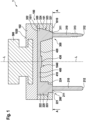
- Fig. 1 is a cross-sectional cut through an example head 1 in accordance with the present disclosure.
- the head 1 has a carrier 100, a cleaning element 200 and a further cleaning element 300 that is of course optional and is used to discuss some aspects that are either alternative or additional aspects.
- the cleaning elements 200 and 300 are connected by a laterally extending arm 400.
- the head 1 comprises an optional connector 500 that may be used to connect the head with a drive unit of a personal care device (see Fig. 4A for an example personal care device).
- the carrier 100 has a front surface 1010 and a back surface 1020.
- the carrier 100 may be made from a front portion 101 and a back portion 102 that may be made in successive molding steps and this structure may serve to completely embed the cleaning elements 200 and 300 in the carrier 100 and/or to connect the carrier with the connector 500.
- the front portion 101 of the carrier 100 has (while the back portion 102 is not yet made) a back surface 1011.
- the cleaning element 200 shown on the left-hand side comprises a non-embedded portion 210 and an embedded portion 220, which embedded portion 220 means the portion of the cleaning element 200 that here is located within the carrier 100 and that ends on the level of the here flat front surface 1010 of the carrier 100.
- the non-embedded portion 210 of the cleaning element 200 has a base end 211 that extends from the front surface, i.e., from the level of the front surface, towards a free end 212 of the non-embedded portion 210 of the cleaning element 200.
- the base end 211 of the non-embedded portion 210 of the cleaning element 200 has a base end cross-sectional area and a base end cross-sectional shape in the level of the front surface 1010.
- the embedded portion 220 of the cleaning element 200 has a top end 221 that lies in the front surface 1010 of the carrier 100 and which top end 221 has a top end cross sectional area and a top end cross-sectional shape. Examples are again discussed with reference to Figs. 2A and 2B .
- the top end cross-sectional area is larger than the base end cross-sectional area for the reasons as already discussed, namely improved chemical and/physical bonding between the embedded portion 220 of the cleaning element 200 and the carrier 100.
- the embedded portion 220 of the cleaning element 200 has a bottom end 222 that is here completely embedded by the carrier 100. Between the top end 221 and the bottom end 222 a middle portion 223 extends. For the cleaning element 200, there is a widening step 224 provided in the middle portion 223, that is an essentially spontaneous widening the embedded portion 220 of the cleaning element 200 that increases the retention force needed to rip out the cleaning element 200 from the carrier 100 or to rip apart the cleaning element 200.
- the bottom end 222 of the embedded portion 220 of the cleaning element 200 may be connected, as is here shown, with a laterally extending arm 400 so that an arm section 410 extends between the bottom end 222 and a center section 430 of the laterally extending arm 400.
- the center section 430 may represent an injection point for the material from which the cleaning element 200 is made during the manufacturing of the head 1.
- the cleaning element 200 and the laterally extending arm 400 may thus be integral with each other.
- the laterally extending arm 400 may extend within a channel that is provided in the back side of the front portion 101 of the carrier 100.
- the further cleaning element 300 shown on the right-hand side comprises a non-embedded portion 310 and an embedded portion 320, which embedded portion 320 means the portion of the further cleaning element 300 that here is located within the carrier 100 and that ends on the level of the here flat front surface 1010 of the carrier 100.
- the non-embedded portion 310 of the further cleaning element 300 has a base end 311 that extends from the front surface, i.e., from the level of the front surface, towards a free end 312 of the non-embedded portion 310 of the cleaning element 200.
- the further cleaning element 300 (like any other cleaning element) may have a structure 313 to support cleaning of a surface such as a tooth surface.
- the base end 311 of the non-embedded portion 310 of the further cleaning element 300 has a base end cross-sectional area and a base end cross-sectional shape in the level of the front surface 1010. Examples are again discussed with reference to Figs. 2A and 2B .
- the embedded portion 320 of the further cleaning element 300 has a top end 321 that lies in the front surface 1010 of the carrier 100 and which top end 321 has a top end cross sectional area and a top end cross-sectional shape. Examples are again discussed with reference to Figs. 2A and 2B .
- the top end cross-sectional area is larger than the base end cross-sectional area for the reasons as already discussed, namely improved chemical and/physical bonding between the embedded portion 320 of the further cleaning element 300 and the carrier 100.
- the embedded portion 320 of the further cleaning element 300 has a bottom end 322 that is here completely embedded by the carrier 100. Between the top end 321 and the bottom end 322 a middle portion 323 extends.
- a widening 324 provided in the middle portion 323, that is an essentially continuous widening the embedded portion 320 of the further cleaning element 300 that increases the retention force needed to rip out the further cleaning element 300 from the carrier 100 or to rip apart the further cleaning element 300.
- the bottom end 322 of the embedded portion 320 of the further cleaning element 300 may be connected with a laterally extending arm 400 so that an arm section 420 extends between the bottom end 322 and a center section 430 of the laterally extending arm 400.
- the center section 430 may represent an injection point for the material from which the further cleaning element 300 is made during the manufacturing of the head 1.
- the further cleaning element 300 and the laterally extending arm 400 may thus be integral with each other.
- the laterally extending arm 400 may extend within a channel that is provided in the back side of the front portion 101 of the carrier 100. In the example shown in Fig. 1 , the laterally extending arm 400 connects the bottom end 222 of the embedded portion 220 of the cleaning element and the bottom end 322 of the embedded portion 320 of the further cleaning element 300.
- Fig. 2A is a cross-sectional cut through a first embodiment of a cleaning element 200A extending from a front surface 1010A of a carrier, where the cross-sectional cut was done in the plane of the front surface 1010A and the viewing direction is top-down as indicated by arrows in Fig. 1 .
- a base end cross-sectional area 215A and a base end cross-sectional shape 216A of a non-embedded portion 210A of the cleaning element 200A are shown.
- a top end cross-sectional area 225A and a top end cross-sectional shape 226A of an embedded portion 220A of the cleaning element 200A are shown.
- the top end cross-sectional area 225A is larger than the base end cross-sectional area 215A and the first fully encompasses the latter.
- the top end cross-sectional shape 226A is circular and the base end cross-sectional shape 216A is circular as well and both are coaxially arranged, which is merely an optional positioning and they may as well be positioned in a non-coaxial manner.
- Fig. 2B is a cross-sectional cut through a second embodiment of a cleaning element 200B extending from a front surface 1010B of a carrier, where the cross-sectional cut was done in the plane of the front surface 1010B and the viewing direction is top-down as indicated by arrows in Fig. 1 .
- a base end cross-sectional area 215B and a base end cross-sectional shape 216B of a non-embedded portion 210B of the cleaning element 200B are shown.
- a top end cross-sectional area 225B and a top end cross-sectional shape 226B of an embedded portion 220B of the cleaning element 200B are shown.
- the top end cross-sectional area 225B is larger than the base end cross-sectional area 215B and the first fully encompasses the latter.
- the top end cross-sectional shape 226B is elliptical and the base end cross-sectional shape 216B is arc-like with a tapering towards one end (giving the impression of a Yin or Yang symbol).
- Figs. 2A and 2B are exemplary only and the skilled person will be able to contemplate various other shapes like triangular, rectangular, star-like, banana-like, kidney-like, half-moon-like, trapezoidal etc.
- Figs. 3A to 3F are depictions of various manufacturing steps of making an example head for a personal care device in accordance with the present disclosure and of intermediate head products and of the final head.
- Fig. 3A is a cross-sectional cut through a schematically depicted mold 600A having a first mold half 610A and a second mold half 620A that define a first cavity 601A for injection molding of a front portion of a carrier.
- the separation line between the two mold halves 610A and 620A s indicated to coincide with a plane defining the front surface of the to be injection molded front portion of the carrier - this position of the separation line is understood to be non-limiting.
- two pins 630A and 640A extend into the first cavity 601A, which pins define through-holes in the front portion of the carrier.
- the second mold half 620A may comprise one or several cavity portions 602A for defining a non-embedded portion of a cleaning element. Such a cavity portion would then be sealed by a pin, as is here the case for pin 640A so that no plastic material would flow into cavity portion 602A during the injection of molten plastic material into the first cavity 601A. While in this cross-sectional cut two pins are shown, it should be understood that this is a non-limiting example shown for sake of presenting the concept and in some embodiments only one pin is used, while in other embodiments two or three or four etc. pins are used ⁇ just as many as injection molded cleaning elements are planned. This shall also not exclude that further cleaning elements made from, e.g., bundles of fibers are present on the carrier together with at least one of the injection molded cleaning elements.
- Fig. 3B is a cross-sectional cut through a front portion 101B of a carrier made by injecting molten plastic material into the first cavity 601A shown in Fig. 3A .
- the front portion 101B of the carrier has two through-holes 102B and 103B that extend between a front surface 1010B and a back surface 1011B of the front portion 101B of the carrier.
- a channel 104B connecting the two through holes 102B and 103B is shown in the back surface 1011B
- Fig. 3C is a cross-sectional cut through a schematically depicted mold 600C having a first mold half 610C and a second mold half 620C that define a second cavity 601C.
- a front portion 101C is inserted into the cavity 601C as an insert. It shall be understood that the front portion 101C may of course be the front portion 101B shown in Fig. 3B .
- the second cavity 601C with the inserted front portion 101C comprises several cavity portions 6011C to 6017C.
- a central channel cavity portion 6011C is provided on the backside of the front portion 101C of the carrier and two channel arms are defined by cavity portions 6012C and 6013C, which two arms cavity portions 6012C and 6013C connect the central channel cavity portion 6011C with through holes in the front portion 101C of the carrier, which through-holes define cavity portions 6014C and 6015C for molding of embedded portions of cleaning elements.
- the second mold half 620C comprises here two cavity portions 6015C and 6016C that are aligned with the cavity portions 6014C and 6015C, respectively, and that allow to mold non-embedded portions of the cleaning elements.
- a injection nozzle 611C is indicated that is positioned in alignment with the central channel cavity portion 6011C, which is to be understood as a non-limiting example.
- Fig. 3D is a cross-sectional cut through a pre-head 105D comprising a front portion of a carrier 101D and two cleaning elements 200D and 300D that may be the result from an injection molding step into the second cavity shown in Fig. 3C .
- the cleaning elements 200D and 300D are integrally connected by a laterally extending arm 400D on the backside of the front portion 101D.
- the plastic materials of the front portion 101D and of the cleaning elements 200D, 300D may be chosen such that the materials form and chemical and/or physical bond.
- Fig. 3E is a cross-sectional cut through a schematically depicted mold 600E having a first mold half 610E and a second mold half 620E that define a third cavity 601E.
- a pre-head 105E is inserted into the third cavity as is a connector 500E that may serve to connect the final head to be molded with a drive mechanism.
- the pre-head 105E may be the pre-head 105D that is shown in Fig. 3D .
- Molten plastic material that will be injected into the third cavity 601E will connect the pre-head 105D and the connector 500D by a physical and/or chemical bond and/or by a positive fit.
- the material to be injected into the third cavity 601E forms a back portion of the carrier and completely embeds the embedded portion of the cleaning elements 200D and 300D as well as the laterally extending arm 400D.
- Fig. 3F is a depiction of a head 1F that may result from the final injection molding step discussed with respect to Fig. 3E .
- the head 1F comprises a carrier 100F, an array of cleaning elements 200F and a connector 500F.
- the connector 500F may comprise a connecting structure 501F to allow the connection with, e.g., a drive mechanism and/or with a locking mechanism (such as a locking pin) as is commonly known in the art.
- the array of cleaning elements 200F comprises two cleaning elements 201F shown in solid lines. It is here indicated by dashed lines that the head 1F may comprise more than the two cleaning elements that were shown and discussed in the previous Figs. 3A to 3E , namely additional cleaning elements 202F.
- Fig. 4A is a depiction of a personal care device 10 realized as an electric toothbrush that comprises a handle section 11 and a replaceable attachment 12 at which a head 14 is provided, preferably a head in accordance with the present disclosure.
- Fig. 4B is a depiction of a replaceable attachment 20 realized as a replacement brush head for an electric toothbrush, which replaceable attachment 20 comprises a head 21, preferably a head in accordance with the present disclosure.
Landscapes
- Engineering & Computer Science (AREA)
- Manufacturing & Machinery (AREA)
- Mechanical Engineering (AREA)
- Health & Medical Sciences (AREA)
- Dentistry (AREA)
- Epidemiology (AREA)
- Life Sciences & Earth Sciences (AREA)
- Animal Behavior & Ethology (AREA)
- General Health & Medical Sciences (AREA)
- Public Health (AREA)
- Veterinary Medicine (AREA)
- Chemical & Material Sciences (AREA)
- Materials Engineering (AREA)
- Brushes (AREA)
- Moulds For Moulding Plastics Or The Like (AREA)
- Surgical Instruments (AREA)
- Orthopedics, Nursing, And Contraception (AREA)
- Printers Or Recording Devices Using Electromagnetic And Radiation Means (AREA)
Abstract
Description
- The present disclosure is concerned with a head for a personal care device, which head comprises a carrier and at least one cleaning element.
- It is known that a head for a personal care device such as a cleaning head for an electric toothbrush comprises cleaning elements and specifically can comprises cleaning elements made from injection molded plastic material.
- There is a general object to provide a head for a personal care device comprising at least one cleaning element that is improved over previously known heads. There is also a general object to provide a method for making such a head.
- In accordance with at least one aspect, a head for a personal care device is provided that comprises a carrier having a front surface, at least one cleaning element partly embedded in the carrier and thus having an embedded cleaning element portion and a non-embedded cleaning element portion, the non-embedded cleaning element portion extending from the front surface of the carrier between a base end on the front surface and a free end and the embedded cleaning element portion extending from the front surface between a top end on the front surface and a bottom end, wherein the base end of the non-embedded cleaning element portion has a base end cross-sectional shape and a base end cross-sectional area, and the top end of the embedded cleaning element portion has a top end cross-sectional shape that is different to the base end cross-sectional shape and a top end cross-sectional area that is larger than the base end cross-sectional area.
- In accordance with at least one aspect, a method for making a head for a personal care device is provided that comprises the steps of
- providing a first cavity in a mold for defining a front portion of a carrier, the mold comprising at least one pin for defining a through-hole in the front portion of the carrier, the through hole having a top end and a bottom end;
- injection molding of the front portion of the carrier;
- providing a second cavity in a mold comprising the front portion of the carrier as an insert, the second cavity comprising at least one cavity portion defining a non-embedded portion of a cleaning element, which cavity portion is an extension of the through-hole in the front portion of the carrier, wherein the cavity portion has a base end having a base end cross-sectional shape and a base end cross-sectional area and the top end of the trough-hole adjacent the base end of the cavity portion that has a top end cross-sectional area that is larger than the base end cross-sectional area, and preferably has a top end cross-sectional shape different to the base end cross-sectional shape;
- injection molding of at least one cleaning element that fills the cavity portion and the through-hole;
- providing a third cavity comprising the front portion of the carrier with the injection molded cleaning element as an insert and a cavity portion defining a back portion of the carrier; and
- injection molding of the back portion of the carrier.
- The present disclosure will be further elucidated by a detailed description of example embodiments and with reference to figures. In the figures
- Fig. 1
- is a cross-sectional cut through an example head in accordance with the present disclosure;
- Fig. 2A
- is a cross-sectional cut through a first example cleaning element taken along the front surface of a head for a personal care device;
- Fig. 2B
- is a cross-sectional cut through a first example cleaning element taken along the front surface of a head for a personal care device;
- Fig. 3A
- is a schematic depiction of a first method of making a head in accordance with the present disclosure, the step comprising providing a first mold cavity for defining a front portion of a carrier having a through hole defined by a pin;
- Fig. 3B
- is a schematic depiction of a first method of making a head in accordance with the present disclosure, the step comprising filling the first mold cavity;
- Fig. 3C
- is a schematic depiction of a first method of making a head in accordance with the present disclosure, the step comprising providing a second mold cavity having the front portion of the carrier molded as shown in
Fig. 3B as an insert and comprising a cavity portion for defining a non-embedded portion of a cleaning element; - Fig. 3D
- is a schematic depiction of a first method of making a head in accordance with the present disclosure, the step comprising filling of the second mold cavity;
- Fig. 3E
- is a schematic depiction of a first method of making a head in accordance with the present disclosure, the step comprising providing a third mold cavity having the front portion of the carrier molded as shown in
Fig. 3D as an insert and comprising a cavity portion for defining a back portion of the carrier; - Fig. 3F
- is a schematic depiction of a first method of making a head in accordance with the present disclosure, the step comprising filling of the third mold cavity;
- Fig. 4A
- is a depiction of a personal care device comprising a head in accordance with the present disclosure; and
- Fig. 4B
- is a depiction of a replaceable attachment for a personal care device comprising a head in accordance with the present disclosure.
- In the context of the present description "personal care" shall mean the nurture (or care) of the skin and of its adnexa (i.e., hairs and nails) and of the teeth and the oral cavity (including the tongue, the gums etc.), where the aim is on the one hand the prevention of illnesses and the maintenance and strengthening of health and on the other hand the cosmetic treatment and improvement of the appearance of the skin and its adnexa. It shall include the maintenance and strengthening of wellbeing. This includes skin care, hair care, and oral care as well as nail care. This further includes grooming activities such as beard care, shaving, and depilation. A "personal care device" thus means any device for performing such nurturing or grooming activity, e.g. (cosmetic) skin treatment devices such as skin massage devices or skin brushes; wet razors; electric shavers or trimmers; electric epilators; and oral care devices such as manual or electric toothbrushes, (electric) flossers, (electric) irrigators, (electric) tongue cleaners, or (electric) gum massagers. This shall not exclude that the proposed personal care device may have a more pronounced benefit in one or several of these nurturing or device areas than in one or several other of these areas. In the present description, an electric toothbrush was chosen to present details of the proposed personal care device. To the extent in which the details are not specific for an electric toothbrush, the proposed technology can be used in any other personal care device.
- In accordance with the present disclosure, a head for a personal care device comprises at least one cleaning element and may comprise at least one or a plurality of further cleaning elements. In the present disclosure, the cleaning elements as discussed are named "cleaning element" and "further cleaning element". They could also have been named "first cleaning element" and "second cleaning element" - there is no difference to be seen in this naming convention. A cleaning element as described herein has an embedded cleaning element portion that extends within a carrier of the head and a non-embedded cleaning element portion that extends outside of the carrier. The cleaning element is understood to be an integral cleaning element, i.e., a cleaning element that is a one-piece element. This shall not exclude that a head in accordance with the present description has other non-integral elements suitable for cleaning, e.g., tufts assembled from a plurality of individual fibers, which are generally known in the art of brushes, e.g., toothbrushes or body brushes. It shall be understood that the carrier of the head has a front surface and that the non-embedded portion of the cleaning element extends from this front surface and that the portion of the cleaning element extending up to and below the front surface is the embedded portion of the cleaning element. For ease of presentability, the front surface of the carrier shown in the figures is a planar surface, but this shall not exclude that the front surface of the carrier is non-planar, specifically non-planar in the area of the cleaning element.
- The carrier may be made from a plastic material, preferably a thermoplastic, where the plastic material may have a Young' modulus of above about 0.2 GPa, preferably of above about 1.0 GPa. The plastic material may be a polypropylene, a polycarbonate, a polyethylene or any other suitable thermoplastic.
- In accordance with the present disclosure, the embedded portion of the at least one cleaning element has a top end that ends on the level of the front surface of the carrier and a bottom end that typically ends somewhere inside of the carrier, even though this shall not exclude that in some embodiments the bottom end ends at a back side of the carrier or even extends beyond such a back surface. The portion of the embedded portion of the cleaning element between the top end and the bottom end may be referred to as a middle portion of the embedded portion of the cleaning element. The top end of the embedded portion of the cleaning element has a top end cross-sectional area defined on the level of the front surface and has a top end cross-sectional shape. The non-embedded portion of the cleaning element extends from the front surface of the carrier between a base end that lies on the level of the front surface of the carrier and a free end. The base end of the embedded portion of the cleaning element has a base end cross-sectional area defined on the level of the front surface and base-end cross-sectional shape.
- In accordance with the present disclosure and proposed head, the top end cross-sectional area of the embedded portion of the cleaning element is larger than the base end cross-sectional area of the non-embedded portion of the cleaning element. Preferably, the top end cross-sectional area is by at least 20% larger, preferably at least 30% or at least 40% or at least 50% or at least 60% or at least 70% or at least 80% or at least 100% larger than the base end cross-sectional area and on an absolute scale the larger top end cross-sectional area has a size of at least 3 mm2, preferably at least 4 mm2 or at least 5 mm2 or at least 6 mm2 or at least 7 mm2 or at least 8 mm2 or at least 9 mm2 or at least 10 mm2. The cleaning element as discussed here is an injection molded cleaning element and shall be secured at the carrier so that it cannot be easily removed, e.g., by biting on it while the head moves. The cleaning element shall thus have a retention force of at least 3N, preferably of at least 4 N or at least 5 N. Several measures can be used to achieve a high retention force and the concept that is used here is a large top end cross-sectional area as this increases the contact area between the outer surface of the embedded portion of the cleaning element and the contacting surface of the carrier. The materials of at least the embedded portion of the cleaning element and of the carrier may be chosen such they form a chemical and/or physical bond when the cleaning element is injection molded. The material from which at least the embedded portion of the cleaning element is made may be a thermoplastic elastomer (TPE). The TPE may have a hardness of below about 60 Shore A, preferably of below about 50 Shore A or of below about 40 Shore A or of about 30 Shore A, where the Shore A hardness is measured in accordance with DIN ISO 7619-1. A soft TPE material leads to a relatively long elongation of the TPE cleaning element when a force is applied to rip it out. Further measures can be added to increase the retention force, specifically an undercut between the carrier and the embedded portion of the cleaning element with respect to the extracting direction. A further measure would be an essentially laterally extending arm that is connected with the bottom end of the embedded portion of the cleaning element, which arm may preferably connect the bottom end of the embedded portion of the cleaning element with a center point of the carrier and the arm may potentially also be connected with a bottom end of an embedded portion of a further cleaning element. It is also contemplated to provide a structure of at least a portion of the outer surface of the embedded portion that is in contact with the carrier in order to increase the overall contact area between the embedded portion and the carrier. The structure may be microscopic or macroscopic.
- The mentioned undercut may preferably be created by a widening of the embedded portion of the cleaning element between the top-end towards the bottom end, preferably a widening occurring in a middle portion of the embedded portion of the cleaning element. With "widening" here a continuous widening is meant, i.e., a change from one cross-sectional area and shape to another cross-sectional area and shape occurring over a certain length so the latter cross-sectional area is larger. Instead of a continuous widening, a step-like widening may be provided in the middle portion of the embedded portion of the cleaning element. Both concepts may also be combined, i.e., a continuous widening and a widening step may both be used in combination, optionally each one or both concepts also in combination with a laterally extending arm.
- A method of making a head in accordance with the present disclosure comprises the steps of:
- providing a first cavity in a mold for defining a front portion of a carrier, the mold comprising at least one pin for defining a through-hole in the front portion of the carrier, the through hole having a top end at a front surface of the front portion of the carrier and a bottom end at a back side of the front portion of the carrier;
- injection molding of the front portion of the carrier by filling the first mold cavity with a plastic material;
- providing a second cavity in a mold (which may be the same mold as the mold used in the first step above) and comprising the front portion of the carrier as an insert (the front portion of the carrier may have been transferred into the second mold cavity of the front portion may just be remained in the first cavity), the second cavity comprising at least one cavity portion defining a non-embedded portion of a cleaning element (this cavity portion may have been occluded by the pin and thus may have been opened by retracting the pin), which cavity portion is an extension of the through-hole in the front portion of the carrier, wherein this cavity portion has a base end having a base end cross-sectional shape and a base end cross-sectional area and the top end of the trough-hole adjacent the base end of the cavity portion that has a top end cross-sectional area that is larger than the base end cross-sectional area,
- optionally wherein a top end cross-sectional shape of the through-hole is different to the base end cross-sectional shape;
- injection molding of at least one cleaning element that fills the cavity portion and the through-hole with a plastic material, preferably a thermoplastic elastomer;
- providing a third cavity comprising the front portion of the carrier with the injection molded cleaning element as an insert (the carrier with injection molded cleaning element may be transferred into the third mold cavity or a first mold half defining the second mold cavity may remain together with the carrier with the molded cleaning element and a new second mold half may be used to define the third mold cavity) and a cavity portion defining a back portion of the carrier; and
- injection molding of the back portion of the carrier.
- The method may include one or several or all of the following optional steps:
- choosing a plastic material for injection molding of the front portion of the carrier and choosing a plastic material for injection molding of the cleaning element, wherein both materials are chosen such that they form a chemical and/or physical bonding;
- providing the pin for defining the through-hole having a shape such that the through-hole widens from the top end towards a middle portion or the bottom end of the through hole and/or providing the pin for defining the through-hole having a shape such that the through-hole comprises a widening step between the top end and the bottom end of the through hole;
- providing at least one further pin for defining a further through-hole in the front portion of the carrier and injection molding the cleaning element and the further cleaning element and also filling of a cavity portion of the second mold cavity defining a channel that connects the bottom ends of the two cleaning elements.
- The method to measure the retention force of an integral (or TPE) cleaning element analogously applies the method to measure the tuft retention force as provided by ISO 20126:2012 + Amd 1:2018 ("Dentistry - Manual toothbrushes - General requirements and test methods"). The force range for measuring the retention force of integral/TPE cleaning elements is to be chosen such that the lower retention forces of an integral cleaning element can be reliably measured - the sensor may have a maximum force range value of 100 N.
- An example integral cleaning element has a base end-cross-sectional area of the not embedded portion that is slightly arc-shaped and has a length of about 5mm and a width of about 1mm. The top end cross-sectional area of the embedded portion is wider by 0.3mm in all directions - the top end cross-section area of the embedded portion is in this example about 80% larger than the base end cross-sectional area of the not embedded portion of the cleaning element. The material of the carrier was a polypropylene, specifically an unfilled polypropylene homopolymer for injection molding, and the TPE material of the integral cleaning element (a TPE-O, unfilled high performance thermoplastic elastomer with high flow rate) was having a hardness of 35 Shore A. The retention force of these cleaning elements was measured and a retention force of at least 3 N, typically of at least 4 N was found and most cleaning elements had a retention force of at least 5 N. In case the above mentioned 0.3 mm are reduced to 0.1 mm the increase area would be about 25% and in case of 0.2 mm this increased area would be about 50%. In case the not embedded portion would have a circular base end cross-sectional area having a diameter of 1 mm and the top end cross-sectional area would be by 0.3 mm, the increase would be 156%.
-
Fig. 1 is a cross-sectional cut through an example head 1 in accordance with the present disclosure. The head 1 has acarrier 100, acleaning element 200 and afurther cleaning element 300 that is of course optional and is used to discuss some aspects that are either alternative or additional aspects. Thecleaning elements arm 400. Further, the head 1 comprises anoptional connector 500 that may be used to connect the head with a drive unit of a personal care device (seeFig. 4A for an example personal care device). - The
carrier 100 has afront surface 1010 and aback surface 1020. Thecarrier 100 may be made from afront portion 101 and aback portion 102 that may be made in successive molding steps and this structure may serve to completely embed thecleaning elements carrier 100 and/or to connect the carrier with theconnector 500. As will be explained in more detail in connection with the manufacturing method with reference toFigs. 3A to 3E further below, thefront portion 101 of thecarrier 100 has (while theback portion 102 is not yet made) aback surface 1011. - The
cleaning element 200 shown on the left-hand side comprises anon-embedded portion 210 and an embeddedportion 220, which embeddedportion 220 means the portion of thecleaning element 200 that here is located within thecarrier 100 and that ends on the level of the here flatfront surface 1010 of thecarrier 100. Thenon-embedded portion 210 of thecleaning element 200 has abase end 211 that extends from the front surface, i.e., from the level of the front surface, towards afree end 212 of thenon-embedded portion 210 of thecleaning element 200. Thebase end 211 of thenon-embedded portion 210 of thecleaning element 200 has a base end cross-sectional area and a base end cross-sectional shape in the level of thefront surface 1010. Examples are discussed with reference toFigs. 2A and 2B . The embeddedportion 220 of thecleaning element 200 has atop end 221 that lies in thefront surface 1010 of thecarrier 100 and whichtop end 221 has a top end cross sectional area and a top end cross-sectional shape. Examples are again discussed with reference toFigs. 2A and 2B . In accordance with the present disclosure, the top end cross-sectional area is larger than the base end cross-sectional area for the reasons as already discussed, namely improved chemical and/physical bonding between the embeddedportion 220 of thecleaning element 200 and thecarrier 100. - The embedded
portion 220 of thecleaning element 200 has abottom end 222 that is here completely embedded by thecarrier 100. Between thetop end 221 and the bottom end 222 amiddle portion 223 extends. For thecleaning element 200, there is a wideningstep 224 provided in themiddle portion 223, that is an essentially spontaneous widening the embeddedportion 220 of thecleaning element 200 that increases the retention force needed to rip out thecleaning element 200 from thecarrier 100 or to rip apart thecleaning element 200. Thebottom end 222 of the embeddedportion 220 of thecleaning element 200 may be connected, as is here shown, with a laterally extendingarm 400 so that anarm section 410 extends between thebottom end 222 and acenter section 430 of the laterally extendingarm 400. Thecenter section 430 may represent an injection point for the material from which thecleaning element 200 is made during the manufacturing of the head 1. Thecleaning element 200 and the laterally extendingarm 400 may thus be integral with each other. The laterally extendingarm 400 may extend within a channel that is provided in the back side of thefront portion 101 of thecarrier 100. - The
further cleaning element 300 shown on the right-hand side comprises anon-embedded portion 310 and an embeddedportion 320, which embeddedportion 320 means the portion of thefurther cleaning element 300 that here is located within thecarrier 100 and that ends on the level of the here flatfront surface 1010 of thecarrier 100. Thenon-embedded portion 310 of thefurther cleaning element 300 has abase end 311 that extends from the front surface, i.e., from the level of the front surface, towards afree end 312 of thenon-embedded portion 310 of thecleaning element 200. As is shown by way of example, the further cleaning element 300 (like any other cleaning element) may have astructure 313 to support cleaning of a surface such as a tooth surface. Thebase end 311 of thenon-embedded portion 310 of thefurther cleaning element 300 has a base end cross-sectional area and a base end cross-sectional shape in the level of thefront surface 1010. Examples are again discussed with reference toFigs. 2A and 2B . The embeddedportion 320 of thefurther cleaning element 300 has atop end 321 that lies in thefront surface 1010 of thecarrier 100 and whichtop end 321 has a top end cross sectional area and a top end cross-sectional shape. Examples are again discussed with reference toFigs. 2A and 2B . In accordance with the present disclosure, the top end cross-sectional area is larger than the base end cross-sectional area for the reasons as already discussed, namely improved chemical and/physical bonding between the embeddedportion 320 of thefurther cleaning element 300 and thecarrier 100. - The embedded
portion 320 of thefurther cleaning element 300 has abottom end 322 that is here completely embedded by thecarrier 100. Between thetop end 321 and the bottom end 322 amiddle portion 323 extends. For thefurther cleaning element 300, there is a widening 324 provided in themiddle portion 323, that is an essentially continuous widening the embeddedportion 320 of thefurther cleaning element 300 that increases the retention force needed to rip out thefurther cleaning element 300 from thecarrier 100 or to rip apart thefurther cleaning element 300. Thebottom end 322 of the embeddedportion 320 of thefurther cleaning element 300 may be connected with a laterally extendingarm 400 so that anarm section 420 extends between thebottom end 322 and acenter section 430 of the laterally extendingarm 400. Thecenter section 430 may represent an injection point for the material from which thefurther cleaning element 300 is made during the manufacturing of the head 1. Thefurther cleaning element 300 and the laterally extendingarm 400 may thus be integral with each other. The laterally extendingarm 400 may extend within a channel that is provided in the back side of thefront portion 101 of thecarrier 100. In the example shown inFig. 1 , the laterally extendingarm 400 connects thebottom end 222 of the embeddedportion 220 of the cleaning element and thebottom end 322 of the embeddedportion 320 of thefurther cleaning element 300. -
Fig. 2A is a cross-sectional cut through a first embodiment of acleaning element 200A extending from afront surface 1010A of a carrier, where the cross-sectional cut was done in the plane of thefront surface 1010A and the viewing direction is top-down as indicated by arrows inFig. 1 . In this top-down view, a base endcross-sectional area 215A and a base endcross-sectional shape 216A of anon-embedded portion 210A of thecleaning element 200A are shown. Further, a top endcross-sectional area 225A and a top endcross-sectional shape 226A of an embeddedportion 220A of thecleaning element 200A are shown. In this example, the top endcross-sectional area 225A is larger than the base endcross-sectional area 215A and the first fully encompasses the latter. In this example, the top endcross-sectional shape 226A is circular and the base endcross-sectional shape 216A is circular as well and both are coaxially arranged, which is merely an optional positioning and they may as well be positioned in a non-coaxial manner. -
Fig. 2B is a cross-sectional cut through a second embodiment of acleaning element 200B extending from afront surface 1010B of a carrier, where the cross-sectional cut was done in the plane of thefront surface 1010B and the viewing direction is top-down as indicated by arrows inFig. 1 . In this top-down view, a base endcross-sectional area 215B and a base endcross-sectional shape 216B of anon-embedded portion 210B of thecleaning element 200B are shown. Further, a top endcross-sectional area 225B and a top endcross-sectional shape 226B of an embeddedportion 220B of thecleaning element 200B are shown. In this example, the top endcross-sectional area 225B is larger than the base endcross-sectional area 215B and the first fully encompasses the latter. In this example, the top endcross-sectional shape 226B is elliptical and the base endcross-sectional shape 216B is arc-like with a tapering towards one end (giving the impression of a Yin or Yang symbol). - The shapes shown in
Figs. 2A and 2B are exemplary only and the skilled person will be able to contemplate various other shapes like triangular, rectangular, star-like, banana-like, kidney-like, half-moon-like, trapezoidal etc. -
Figs. 3A to 3F are depictions of various manufacturing steps of making an example head for a personal care device in accordance with the present disclosure and of intermediate head products and of the final head. -
Fig. 3A is a cross-sectional cut through a schematically depictedmold 600A having afirst mold half 610A and asecond mold half 620A that define afirst cavity 601A for injection molding of a front portion of a carrier. The separation line between the twomold halves pins first cavity 601A, which pins define through-holes in the front portion of the carrier. It is indicated by a dashed line that thesecond mold half 620A may comprise one orseveral cavity portions 602A for defining a non-embedded portion of a cleaning element. Such a cavity portion would then be sealed by a pin, as is here the case forpin 640A so that no plastic material would flow intocavity portion 602A during the injection of molten plastic material into thefirst cavity 601A. While in this cross-sectional cut two pins are shown, it should be understood that this is a non-limiting example shown for sake of presenting the concept and in some embodiments only one pin is used, while in other embodiments two or three or four etc. pins are used ― just as many as injection molded cleaning elements are planned. This shall also not exclude that further cleaning elements made from, e.g., bundles of fibers are present on the carrier together with at least one of the injection molded cleaning elements. -
Fig. 3B is a cross-sectional cut through afront portion 101B of a carrier made by injecting molten plastic material into thefirst cavity 601A shown inFig. 3A . Thefront portion 101B of the carrier has two through-holes front surface 1010B and aback surface 1011B of thefront portion 101B of the carrier. Achannel 104B connecting the two throughholes back surface 1011B -
Fig. 3C is a cross-sectional cut through a schematically depictedmold 600C having afirst mold half 610C and asecond mold half 620C that define asecond cavity 601C. Afront portion 101C is inserted into thecavity 601C as an insert. It shall be understood that thefront portion 101C may of course be thefront portion 101B shown inFig. 3B . Thesecond cavity 601C with the insertedfront portion 101C comprisesseveral cavity portions 6011C to 6017C. A centralchannel cavity portion 6011C is provided on the backside of thefront portion 101C of the carrier and two channel arms are defined bycavity portions arms cavity portions channel cavity portion 6011C with through holes in thefront portion 101C of the carrier, which through-holes definecavity portions second mold half 620C comprises here twocavity portions cavity portions Fig. 3 ainjection nozzle 611C is indicated that is positioned in alignment with the centralchannel cavity portion 6011C, which is to be understood as a non-limiting example. -
Fig. 3D is a cross-sectional cut through a pre-head 105D comprising a front portion of acarrier 101D and twocleaning elements Fig. 3C . Thecleaning elements arm 400D on the backside of thefront portion 101D. As was mentioned before, the plastic materials of thefront portion 101D and of thecleaning elements -
Fig. 3E is a cross-sectional cut through a schematically depictedmold 600E having afirst mold half 610E and asecond mold half 620E that define athird cavity 601E. A pre-head 105E is inserted into the third cavity as is aconnector 500E that may serve to connect the final head to be molded with a drive mechanism. The pre-head 105E may be the pre-head 105D that is shown inFig. 3D . Molten plastic material that will be injected into thethird cavity 601E will connect the pre-head 105D and the connector 500D by a physical and/or chemical bond and/or by a positive fit. The material to be injected into thethird cavity 601E forms a back portion of the carrier and completely embeds the embedded portion of thecleaning elements arm 400D. -
Fig. 3F is a depiction of ahead 1F that may result from the final injection molding step discussed with respect toFig. 3E . Thehead 1F comprises acarrier 100F, an array of cleaningelements 200F and aconnector 500F. Theconnector 500F may comprise a connectingstructure 501F to allow the connection with, e.g., a drive mechanism and/or with a locking mechanism (such as a locking pin) as is commonly known in the art. The array of cleaningelements 200F comprises twocleaning elements 201F shown in solid lines. It is here indicated by dashed lines that thehead 1F may comprise more than the two cleaning elements that were shown and discussed in the previousFigs. 3A to 3E , namelyadditional cleaning elements 202F. -
Fig. 4A is a depiction of apersonal care device 10 realized as an electric toothbrush that comprises ahandle section 11 and areplaceable attachment 12 at which ahead 14 is provided, preferably a head in accordance with the present disclosure. -
Fig. 4B is a depiction of areplaceable attachment 20 realized as a replacement brush head for an electric toothbrush, whichreplaceable attachment 20 comprises ahead 21, preferably a head in accordance with the present disclosure. - The dimensions and values disclosed herein are not to be understood as being strictly limited to the exact numerical values recited. Instead, unless otherwise specified, each such dimension is intended to mean both the recited value and a functionally equivalent range surrounding that value. For example, a dimension disclosed as "40 mm" is intended to mean "about 40 mm."
Claims (15)
- A head for a personal care device comprisinga carrier having a front surface;at least one cleaning element, preferably an integral cleaning element, partly embedded in the carrier and thus having an embedded cleaning element portion and a non-embedded cleaning element portion, the non-embedded cleaning element portion extending from the front surface of the carrier between a base end on the front surface and a free end and the embedded cleaning element portion extending from the front surface between a top end on the front surface and a bottom end,wherein the base end of the non-embedded cleaning element portion has a base end cross-sectional shape and a base end cross-sectional area, and the top end of the embedded cleaning element portion has a top end cross-sectional shape that is different to the base end cross-sectional shape and a top end cross-sectional area that is larger than the base end cross-sectional area.
- The head in accordance with claim 1, wherein the top end cross-sectional area of the embedded cleaning element portion is larger by at least about 30% than the base end cross-sectional area of the non-embedded cleaning element portion.
- The head in accordance with claim 1 or claim 2, wherein the cleaning element material is a thermoplastic elastomer.
- The head in accordance with one of claims 1 to 3, wherein a material from which the embedded cleaning element portion is made and a material from which the carrier is made are chemically and/or physically bonded.
- The head in accordance with one of claims 1 to 4, wherein the embedded cleaning element portion widens from the top end towards a middle portion or the bottom end.
- The head in accordance with one of claims 1 to 5, wherein the embedded cleaning element portion comprises a widening step between the top end and the bottom end of the embedded cleaning element portion.
- The head in accordance with one of claims 1 to 6, wherein an integral arm connects the bottom end of the embedded cleaning element portion with a center point on or in the carrier, the center point being laterally displaced from the bottom end.
- The head in accordance with claim 7, wherein at least one further integral arm connects the center point and a bottom end of an embedded cleaning element portion of another cleaning element.
- The head in accordance with one of claims 1 to 8, wherein a retention force of the cleaning element is at least 3 Newton.
- A method of making a head for a personal care device, preferably a head in accordance with the preceding claims, comprising the steps of:providing a first cavity in a mold for defining a front portion of a carrier, the mold comprising at least one pin for defining a through-hole in the front portion of the carrier, the through hole having a top end and a bottom end;injection molding of the front portion of the carrier;providing a second cavity in a mold comprising the front portion of the carrier as an insert, the second cavity comprising at least one cavity portion defining a non-embedded portion of a cleaning element, which cavity portion is an extension of the through-hole in the front portion of the carrier, wherein the cavity portion has a base end having a base end cross-sectional shape and a base end cross-sectional area and the top end of the trough-hole adjacent the base end of the cavity portion that has a top end cross-sectional area that is larger than the base end cross-sectional area, and preferably has a top end cross-sectional shape different to the base end cross-sectional shape;injection molding of at least one cleaning element that fills the cavity portion and the through-hole;providing a third cavity comprising the front portion of the carrier with the injection molded cleaning element as an insert and a cavity portion defining a back portion of the carrier; andinjection molding of the back portion of the carrier.
- The method in accordance with claim 10, comprising the further steps of:choosing a plastic material for injection molding of the front portion of the carrier, preferably wherein the plastic material is a thermoplastic such as a polypropylene, a polycarbonate or a polyethylene;choosing a plastic material for injection molding of the cleaning element, preferably wherein the material is a thermoplastic elastomer;wherein the both materials are chosen such that they form a chemical and/or physical bonding.
- The method in accordance with claim 10 or claim 11, comprising the step of providing the pin for defining the through-hole having a shape such that the through-hole widens from the top end towards a middle portion or the bottom end of the through hole.
- The method in accordance with claim 10 or claim 11, comprising the step of providing the pin for defining the through-hole having a shape such that the through-hole comprises a widening step between the top end and the bottom end of the through hole.
- The method in accordance with any one of claims 10 to 13, wherein the material for injection molding of the cleaning element is a thermoplastic elastomer, preferably wherein the thermoplastic elastomer has a hardness of below 50 Shore A.
- The method in accordance with any one of claims 10 to 14, wherein providing the first cavity comprises providing at least a further pin for defining a further through-hole in the front portion of the carrier and wherein injection molding of the at least one cleaning element comprises injection molding of at least the cleaning element and the further cleaning element and filling of a cavity portion of the second mold defining channel with the injected material to create an integral arm connecting the bottom ends of the two cleaning element.
Priority Applications (7)
| Application Number | Priority Date | Filing Date | Title |
|---|---|---|---|
| ES21199135T ES3014734T3 (en) | 2021-09-27 | 2021-09-27 | Head for a personal care device and method of making thereof |
| EP21199135.1A EP4154761B1 (en) | 2021-09-27 | 2021-09-27 | Head for a personal care device and method of making thereof |
| CA3231681A CA3231681A1 (en) | 2021-09-27 | 2022-09-08 | Head for a personal care device |
| PCT/IB2022/058453 WO2023047231A1 (en) | 2021-09-27 | 2022-09-08 | Head for a personal care device |
| JP2024516540A JP2024533518A (en) | 2021-09-27 | 2022-09-08 | Heads for personal care devices |
| CN202280063558.7A CN118119320A (en) | 2021-09-27 | 2022-09-08 | Head for personal care device |
| US17/950,646 US12551003B2 (en) | 2021-09-27 | 2022-09-22 | Head for a personal care device |
Applications Claiming Priority (1)
| Application Number | Priority Date | Filing Date | Title |
|---|---|---|---|
| EP21199135.1A EP4154761B1 (en) | 2021-09-27 | 2021-09-27 | Head for a personal care device and method of making thereof |
Publications (2)
| Publication Number | Publication Date |
|---|---|
| EP4154761A1 true EP4154761A1 (en) | 2023-03-29 |
| EP4154761B1 EP4154761B1 (en) | 2025-01-15 |
Family
ID=77998726
Family Applications (1)
| Application Number | Title | Priority Date | Filing Date |
|---|---|---|---|
| EP21199135.1A Active EP4154761B1 (en) | 2021-09-27 | 2021-09-27 | Head for a personal care device and method of making thereof |
Country Status (7)
| Country | Link |
|---|---|
| US (1) | US12551003B2 (en) |
| EP (1) | EP4154761B1 (en) |
| JP (1) | JP2024533518A (en) |
| CN (1) | CN118119320A (en) |
| CA (1) | CA3231681A1 (en) |
| ES (1) | ES3014734T3 (en) |
| WO (1) | WO2023047231A1 (en) |
Citations (5)
| Publication number | Priority date | Publication date | Assignee | Title |
|---|---|---|---|---|
| GB601371A (en) * | 1946-05-06 | 1948-05-04 | John Denman Dean | Improvements in or relating to hair and like brushes |
| JP2003061753A (en) * | 2001-08-24 | 2003-03-04 | Kao Corp | Brush manufacturing method |
| EP1726237A1 (en) * | 2005-05-25 | 2006-11-29 | M + C Schiffer GmbH | Brush and associated production method |
| JP6423630B2 (en) * | 2014-06-30 | 2018-11-14 | 花王株式会社 | Pore cleaning brush |
| US20210068526A1 (en) * | 2018-03-29 | 2021-03-11 | Sangsi Co., Ltd. | Toothbrush |
Family Cites Families (118)
| Publication number | Priority date | Publication date | Assignee | Title |
|---|---|---|---|---|
| US1601217A (en) * | 1924-11-17 | 1926-09-28 | Northboro Brush Company | Brush |
| US2273717A (en) * | 1938-01-14 | 1942-02-17 | Lactona Inc | Brush |
| US2363647A (en) * | 1942-09-02 | 1944-11-28 | Hughes Autograf Brush Company | Hairbrush cover |
| US2358464A (en) * | 1942-10-08 | 1944-09-19 | Hughes Autograf Brush Company | Bristle holder for brushes |
| US2409490A (en) * | 1944-05-11 | 1946-10-15 | Toledo Automatic Brush Machine | Tuft anchoring means for brushes |
| US2488873A (en) * | 1945-01-12 | 1949-11-22 | Prophylactic Brush Co | Toothbrush and method of making |
| US2542709A (en) * | 1947-09-27 | 1951-02-20 | Fuller Brush Co | Brush structure with bristles held in channel strip |
| US2482928A (en) * | 1948-03-26 | 1949-09-27 | Neff Augusta | Needle hairbrush |
| DE941364C (en) | 1954-06-03 | 1956-04-12 | Edwin Grether | Process for the production of brushes, the brush body and bristles of which consist of one piece which is produced by the injection molding process, and brushes according to this process |
| US2923598A (en) | 1954-06-30 | 1960-02-02 | Pittsburgh Plate Glass Co | Method of forming filaments embodying polyurethane resins |
| US2882544A (en) * | 1957-10-23 | 1959-04-21 | Puzant H Hadidian | Tooth brush |
| US3076218A (en) | 1961-06-08 | 1963-02-05 | Johnson & Johnson | Fluorinated toothbrush bristle and method of making same |
| DE2812746C2 (en) | 1978-03-23 | 1985-05-30 | Friedrich Schlesinger, Maschinenfabrik, 3558 Frankenberg | Machine for the production of brushes |
| JPS62148610A (en) | 1985-11-19 | 1987-07-02 | 株式会社 新和製作所 | Production of fiber bundle for brush |
| JP2732875B2 (en) | 1988-02-03 | 1998-03-30 | コロネツト‐ヴエルケ ハインリツヒ シユレルフ ゲゼルシヤフト ミツト ベシユレンクテル ハフツング | How to make bristle products |
| US5040260A (en) | 1989-03-16 | 1991-08-20 | Michaels George G | Tooth cleaning and polishing device |
| JPH0631940Y2 (en) * | 1989-05-10 | 1994-08-24 | ライオン株式会社 | toothbrush |
| DE59007034D1 (en) | 1989-06-24 | 1994-10-13 | Frisetta Gmbh | Method and device for producing bristle fields or bristle bundles. |
| US5318352A (en) * | 1990-11-20 | 1994-06-07 | Oraline International B.V. | Method of making a toothbrush |
| JPH0580324U (en) | 1992-04-01 | 1993-11-02 | 花王株式会社 | toothbrush |
| DE4314692C2 (en) | 1993-05-04 | 1998-11-26 | Zahoransky Anton Gmbh & Co | Method and device for manufacturing brushes |
| DE4415886A1 (en) * | 1994-05-05 | 1995-11-09 | Coronet Werke Gmbh | Process for the production of bristle goods by injection molding |
| DE19507364A1 (en) * | 1995-03-03 | 1996-09-05 | Coronet Werke Gmbh | Brush, in particular hygiene brush |
| JPH0956479A (en) * | 1995-08-29 | 1997-03-04 | Lion Corp | Brush and manufacturing method thereof |
| US6996870B2 (en) | 1995-12-29 | 2006-02-14 | Colgate-Palmolive Company | Contouring toothbrush head |
| US6036277A (en) * | 1996-02-14 | 2000-03-14 | Coronet-Werke Gmbh | Method for the manufacture of brushware |
| CN2259084Y (en) | 1996-05-13 | 1997-08-13 | 石汀 | Toothbrush with adjustable hardness hairs |
| TW414035U (en) | 1996-05-14 | 2000-12-01 | Kao Corp | Toothbrush |
| DE19743556A1 (en) | 1997-10-01 | 1999-04-08 | Schiffer Fa M & C | Method and device for producing a toothbrush |
| DE19745024A1 (en) | 1997-10-11 | 1999-04-15 | Zahoransky Anton Gmbh & Co | Brush-producing machine with multiple compartment magazine |
| GB9816914D0 (en) | 1998-08-05 | 1998-09-30 | Smithkline Beecham Gmbh | Novel device |
| US6035476A (en) * | 1998-09-10 | 2000-03-14 | Optiva Corporation | Brushhead for a toothbrush |
| DE19909435A1 (en) | 1999-03-04 | 2000-09-07 | Coronet Werke Gmbh | Method and device for the production of bristle products and bristle products produced thereafter |
| GB9907996D0 (en) | 1999-04-09 | 1999-06-02 | Smithkline Beecham Gmbh | Toothbrush |
| JP2001190333A (en) * | 2000-01-17 | 2001-07-17 | Lion Corp | Toothbrush and manufacturing method thereof |
| DE10015062B4 (en) | 2000-03-25 | 2010-05-12 | Braun Gmbh | Brush head and method of making such a brush head |
| DE20006311U1 (en) | 2000-04-06 | 2001-08-09 | G.B. Boucherie N.V., Izegem | Device for attaching tufts of bristles to brush bodies |
| US6865767B1 (en) | 2000-06-05 | 2005-03-15 | James A. Gavney, Jr. | Device with multi-structural contact elements |
| JP4132744B2 (en) * | 2000-08-23 | 2008-08-13 | 花王株式会社 | Brush manufacturing method and apparatus |
| US7434288B2 (en) | 2000-09-19 | 2008-10-14 | Gavney Jr James A | Oral care device with multi-structural contact elements |
| US20060230563A1 (en) | 2000-09-19 | 2006-10-19 | Gavney James A Jr | Oral care device with multi-structural contact elements |
| JP3932903B2 (en) * | 2001-06-14 | 2007-06-20 | 松下電工株式会社 | electric toothbrush |
| JP2003144232A (en) * | 2001-08-30 | 2003-05-20 | Lion Corp | Manufacturing method of toothbrush handle |
| DE10164336A1 (en) | 2001-12-28 | 2003-07-17 | Trisa Holding Ag Triengen | Toothbrush and method of making such a toothbrush |
| DE10212701B4 (en) | 2002-03-21 | 2015-05-13 | Geka Gmbh | Bristle, method and device for its manufacture, and bristles |
| DE10217527B4 (en) | 2002-04-19 | 2012-06-21 | Anton Zahoransky Gmbh & Co. | Method of making brushes and brush made therefrom |
| US6735803B2 (en) | 2002-06-03 | 2004-05-18 | Youti Kuo | Electrical dentifrice-dispensing toothbrush with replaceable bristle unit and refillable cartridge |
| US7845042B2 (en) * | 2002-08-09 | 2010-12-07 | Colgate-Palmolive Company | Oral care implement |
| EP2510830B1 (en) | 2002-08-09 | 2013-12-25 | Colgate-Palmolive Company | Method of forming a toothbrush |
| US7836539B2 (en) * | 2002-08-09 | 2010-11-23 | Colgate-Palmolive Company | Oral care implement |
| US7614111B2 (en) | 2002-08-09 | 2009-11-10 | Colgate-Palmolive Company | Oral care implement |
| US7725980B2 (en) | 2004-12-15 | 2010-06-01 | Colgate-Palmolive Company | Oral care implement |
| BRPI0307110B1 (en) | 2002-12-03 | 2017-03-28 | Kwon Sung-Wook | tapered needle-shaped toothbrush at one end and method of making it |
| DE10259723A1 (en) | 2002-12-19 | 2004-07-01 | Trisa Holding Ag | Toothbrush and process for making it |
| DE102004026461A1 (en) | 2004-05-29 | 2005-12-15 | Braun Gmbh | Brush head for electric and / or manual toothbrushes |
| KR100597687B1 (en) | 2004-09-21 | 2006-07-10 | 주식회사 엘지생활건강 | toothbrush |
| CA2596685C (en) | 2005-02-02 | 2014-04-01 | Sunstar Inc. | Toothbrush |
| DE102006026712A1 (en) | 2006-06-08 | 2007-12-13 | M + C Schiffer Gmbh | Toothbrush and method for its manufacture |
| US20090229064A1 (en) * | 2006-11-02 | 2009-09-17 | Robinson Dane Q | Brush and bristle assembly therefor |
| US20080104785A1 (en) * | 2006-11-02 | 2008-05-08 | Robinson Dane Q | Bristle assembly for a brush and related method |
| US8056176B2 (en) * | 2007-01-25 | 2011-11-15 | The Procter & Gamble Company | Toothbrushes |
| US8032971B2 (en) | 2007-02-23 | 2011-10-11 | Colgate-Palmolive Company | Oral care implement having tooth whitening elements |
| DE102007018766A1 (en) | 2007-04-20 | 2008-10-23 | Braun Gmbh | toothbrush |
| US20090007357A1 (en) | 2007-05-07 | 2009-01-08 | The Gillette Company | Oral Hygiene Implements |
| DE102008039778A1 (en) | 2008-08-26 | 2010-03-04 | Firma G.B. Boucherie N.V. | Method for producing brushes, in particular toothbrushes |
| US8434190B2 (en) * | 2008-09-01 | 2013-05-07 | Braun Gmbh | Toothbrush and method of manufacturing it |
| US9655435B2 (en) | 2008-12-15 | 2017-05-23 | Glaxosmithkline Consumer Healthcare Gmbh & Co., Kg | Toothbrush bristle arrangement |
| EP2243394A1 (en) | 2009-04-21 | 2010-10-27 | M+C Schiffer GmbH | Method for creating a brush bundle and a device for carrying out the method |
| DE102009039514A1 (en) | 2009-08-31 | 2011-03-03 | Gb Boucherie Nv | Method for producing brushes, in particular toothbrushes |
| US20110099739A1 (en) * | 2009-11-05 | 2011-05-05 | Edward Whillock | Interchangeable tooth brush and associated method for promoting oral health |
| ES2972464T3 (en) | 2009-11-13 | 2024-06-12 | Sunstar Inc | Core/sheath composite filament for toothbrushes, and the toothbrush that uses it |
| BR112012014065B1 (en) | 2009-12-10 | 2020-03-10 | Braun Gmbh | TOOTHBRUSH |
| JP2012000150A (en) * | 2010-06-14 | 2012-01-05 | Panasonic Electric Works Co Ltd | Brush body and toothbrush including the same |
| JP2012000148A (en) | 2010-06-14 | 2012-01-05 | Panasonic Electric Works Co Ltd | Brush body and toothbrush including the same |
| EP2420157B1 (en) | 2010-08-18 | 2016-03-30 | Trisa Holding AG | Toothbrush with brush topography structuring |
| WO2012083488A1 (en) | 2010-12-21 | 2012-06-28 | Cogate-Palmolive Company | Oral care implement |
| EP2661191B1 (en) * | 2011-01-04 | 2019-06-12 | Trisa Holding AG | Toothbrush with injection-moulded bristles |
| JP3172569U (en) | 2011-03-03 | 2012-01-05 | リジェンティス株式会社 | Welding toothbrush and its manufacturing method. |
| JP5224618B2 (en) | 2011-04-01 | 2013-07-03 | 花王株式会社 | Brush manufacturing method and apparatus |
| EP2720575B1 (en) | 2011-06-15 | 2018-11-28 | The Gillette Company LLC | Oral care instrument whose head is provided with two flexible wings |
| EP2534973B1 (en) | 2011-06-15 | 2015-04-08 | Braun GmbH | Method and tool for producing a brush head |
| CN103957747B (en) | 2011-12-02 | 2016-02-24 | 博朗有限公司 | Method and device for producing a brushhead segment for an oral care device and brushhead segment produced by said method and/or said device |
| AU2012372822B2 (en) | 2012-03-09 | 2015-02-19 | Colgate-Palmolive Company | Method of forming a head plate and formation of oral care implement using the same |
| DE102012005311B4 (en) | 2012-03-19 | 2021-08-12 | Zahoransky Ag | Device for producing brushes or bristle goods, as well as brushes or bristle goods |
| EP2674061B1 (en) | 2012-06-12 | 2017-07-19 | Braun GmbH | Method and tool for producing a brush head |
| WO2014054911A2 (en) | 2012-10-04 | 2014-04-10 | 비비씨 주식회사 | Method for manufacturing bristles on toothbrush and toothbrush using same |
| DE102012021311A1 (en) | 2012-10-31 | 2014-04-30 | Zahoransky Formenbau Gmbh | Device for manufacturing brush bodies or sub-brush bodies, has one mold half or mold portion, which is movably guided in mold half, is formed for incorporating roof body opposite to bristle bundle-receiving area of another mold half |
| WO2014070542A1 (en) | 2012-11-05 | 2014-05-08 | The Gillette Company | Toothbrush comprising elastomeric cleaning elements over-molded with a harder plastic and method for producing the same |
| US9717324B2 (en) | 2013-05-29 | 2017-08-01 | The Gillette Company Llc | Method for producing a toothbrush and toothbrush produced thereby |
| ES2682256T5 (en) | 2013-06-06 | 2025-11-06 | Procter & Gamble | Head for an oral care implement |
| US20140359957A1 (en) | 2013-06-06 | 2014-12-11 | The Gillette Company | Head for an oral care implement |
| EP2810581B1 (en) | 2013-06-06 | 2018-04-18 | The Gillette Company LLC | Head for an oral care implement |
| US20150097309A1 (en) | 2013-10-04 | 2015-04-09 | The Procter & Gamble Company | Process and apparatus for making tufted article |
| CN105813504B (en) | 2013-12-12 | 2018-05-08 | 高露洁-棕榄公司 | Multi-part bristles having parts with different oral care additives and oral care implements comprising the multi-part bristles |
| EP2886009B1 (en) | 2013-12-18 | 2019-01-30 | The Gillette Company LLC | Device for fusing the ends of thermoplastic filaments and corresponding method |
| ES2774301T3 (en) | 2014-02-21 | 2020-07-20 | Procter & Gamble | Head for an oral care utensil |
| KR20170017891A (en) | 2014-05-29 | 2017-02-15 | 콜게이트-파아므올리브캄파니 | Oral care implement |
| EP2959797A1 (en) | 2014-06-27 | 2015-12-30 | Trisa Holding AG | Toothbrush with moved elements |
| EP3485763B1 (en) | 2014-07-23 | 2020-09-09 | Colgate-Palmolive Company | Oral care implement |
| US11291293B2 (en) | 2014-12-23 | 2022-04-05 | Colgate-Palmolive Company | Oral care implement |
| JP6544003B2 (en) * | 2015-03-31 | 2019-07-17 | サンスター株式会社 | toothbrush |
| CN107624043B (en) | 2015-05-14 | 2020-07-10 | 皇家飞利浦有限公司 | Brush head assembly and method of manufacture |
| EP3294088B1 (en) | 2015-05-14 | 2022-07-06 | Koninklijke Philips N.V. | Brush head assembly and methods of manufacture |
| EP3138437B1 (en) * | 2015-09-03 | 2021-11-10 | Braun GmbH | Method of manufacturing a brush |
| ES2909964T3 (en) | 2015-11-09 | 2022-05-11 | Mc Schiffer Gmbh | Brush head for an electrically powered toothbrush |
| US10136723B2 (en) * | 2015-12-14 | 2018-11-27 | Colgate-Palmolive Company | Oral care implement |
| EP3262974B1 (en) | 2016-06-27 | 2024-06-12 | The Procter & Gamble Company | Method for producing toothbrush heads comprising a two-component-cleaning element |
| EP3262975B1 (en) | 2016-06-28 | 2019-02-20 | The Procter and Gamble Company | Method of making brush |
| MX2019003205A (en) * | 2016-09-26 | 2019-07-04 | Colgate Palmolive Co | Oral care implement or head plate therefor and method of forming the same. |
| WO2019011599A1 (en) | 2017-07-12 | 2019-01-17 | Koninklijke Philips N.V. | Brush head manufacturing method |
| CN109497689B (en) * | 2017-09-15 | 2021-03-12 | 高露洁-棕榄公司 | Oral care implement |
| US10548392B2 (en) * | 2017-11-18 | 2020-02-04 | Tifinity Oral Care, Llc | Toothbrush with bristle-mounting system for retarding bristle strain |
| CA3043205A1 (en) * | 2018-05-21 | 2019-11-21 | Sunstar Americas, Inc. | Toothbrush bristle and bristle tuft |
| EP3753446B1 (en) | 2019-06-21 | 2025-10-22 | The Procter & Gamble Company | Cleaning element carrier and toothbrush head comprising it |
| EP3753447B1 (en) | 2019-06-21 | 2025-12-10 | The Procter & Gamble Company | Method for producing a toothbrush head or a part thereof |
| EP3753449A1 (en) | 2019-06-21 | 2020-12-23 | The Procter & Gamble Company | Hole perforation plate for manufacturing of a toothbrush head and part thereof |
| EP3753445B1 (en) | 2019-06-21 | 2025-12-10 | The Procter & Gamble Company | Tootbrush head and part thereof |
| EP3753448B1 (en) | 2019-06-21 | 2025-12-10 | The Procter & Gamble Company | Method for producing a toothbrush head |
-
2021
- 2021-09-27 EP EP21199135.1A patent/EP4154761B1/en active Active
- 2021-09-27 ES ES21199135T patent/ES3014734T3/en active Active
-
2022
- 2022-09-08 CA CA3231681A patent/CA3231681A1/en active Pending
- 2022-09-08 JP JP2024516540A patent/JP2024533518A/en active Pending
- 2022-09-08 CN CN202280063558.7A patent/CN118119320A/en active Pending
- 2022-09-08 WO PCT/IB2022/058453 patent/WO2023047231A1/en not_active Ceased
- 2022-09-22 US US17/950,646 patent/US12551003B2/en active Active
Patent Citations (5)
| Publication number | Priority date | Publication date | Assignee | Title |
|---|---|---|---|---|
| GB601371A (en) * | 1946-05-06 | 1948-05-04 | John Denman Dean | Improvements in or relating to hair and like brushes |
| JP2003061753A (en) * | 2001-08-24 | 2003-03-04 | Kao Corp | Brush manufacturing method |
| EP1726237A1 (en) * | 2005-05-25 | 2006-11-29 | M + C Schiffer GmbH | Brush and associated production method |
| JP6423630B2 (en) * | 2014-06-30 | 2018-11-14 | 花王株式会社 | Pore cleaning brush |
| US20210068526A1 (en) * | 2018-03-29 | 2021-03-11 | Sangsi Co., Ltd. | Toothbrush |
Also Published As
| Publication number | Publication date |
|---|---|
| CN118119320A (en) | 2024-05-31 |
| EP4154761B1 (en) | 2025-01-15 |
| US12551003B2 (en) | 2026-02-17 |
| US20230097486A1 (en) | 2023-03-30 |
| CA3231681A1 (en) | 2023-03-30 |
| WO2023047231A1 (en) | 2023-03-30 |
| JP2024533518A (en) | 2024-09-12 |
| ES3014734T3 (en) | 2025-04-24 |
Similar Documents
| Publication | Publication Date | Title |
|---|---|---|
| EP2477521B2 (en) | Oral care products | |
| KR101169503B1 (en) | Toothbrush | |
| EP2000049B1 (en) | Toothbrush with enhanced cleaning effects | |
| CA2677180C (en) | Oral hygiene implements having flexible elements, and methods of making the same | |
| EP1558109B1 (en) | Toothbrush | |
| CN103260461B (en) | Oral care implement | |
| CZ288851B6 (en) | Toothbrush with improved efficacy | |
| CN111885944B (en) | Oral care implement and method of forming same | |
| EP4154761B1 (en) | Head for a personal care device and method of making thereof | |
| EP2335644B1 (en) | Oral cleaning section | |
| KR101697244B1 (en) | Toothbrush | |
| JP2019517324A (en) | Hair bundle and head for oral care device and oral care device | |
| HK1123695A (en) | Toothbrush with enhanced cleaning effects | |
| HUP9902896A2 (en) | A toothbrush with elastomer filled flexible head | |
| HK1123698A (en) | Toothbrush with enhanced cleaning effects | |
| HK1123694A (en) | Toothbrush with enhanced cleaning effects | |
| HK1123697A (en) | Toothbrush with enhanced cleaning effects |
Legal Events
| Date | Code | Title | Description |
|---|---|---|---|
| PUAI | Public reference made under article 153(3) epc to a published international application that has entered the european phase |
Free format text: ORIGINAL CODE: 0009012 |
|
| STAA | Information on the status of an ep patent application or granted ep patent |
Free format text: STATUS: THE APPLICATION HAS BEEN PUBLISHED |
|
| AK | Designated contracting states |
Kind code of ref document: A1 Designated state(s): AL AT BE BG CH CY CZ DE DK EE ES FI FR GB GR HR HU IE IS IT LI LT LU LV MC MK MT NL NO PL PT RO RS SE SI SK SM TR |
|
| P01 | Opt-out of the competence of the unified patent court (upc) registered |
Effective date: 20230430 |
|
| STAA | Information on the status of an ep patent application or granted ep patent |
Free format text: STATUS: REQUEST FOR EXAMINATION WAS MADE |
|
| 17P | Request for examination filed |
Effective date: 20230926 |
|
| RBV | Designated contracting states (corrected) |
Designated state(s): AL AT BE BG CH CY CZ DE DK EE ES FI FR GB GR HR HU IE IS IT LI LT LU LV MC MK MT NL NO PL PT RO RS SE SI SK SM TR |
|
| STAA | Information on the status of an ep patent application or granted ep patent |
Free format text: STATUS: EXAMINATION IS IN PROGRESS |
|
| 17Q | First examination report despatched |
Effective date: 20240229 |
|
| GRAP | Despatch of communication of intention to grant a patent |
Free format text: ORIGINAL CODE: EPIDOSNIGR1 |
|
| STAA | Information on the status of an ep patent application or granted ep patent |
Free format text: STATUS: GRANT OF PATENT IS INTENDED |
|
| INTG | Intention to grant announced |
Effective date: 20240925 |
|
| GRAS | Grant fee paid |
Free format text: ORIGINAL CODE: EPIDOSNIGR3 |
|
| GRAA | (expected) grant |
Free format text: ORIGINAL CODE: 0009210 |
|
| STAA | Information on the status of an ep patent application or granted ep patent |
Free format text: STATUS: THE PATENT HAS BEEN GRANTED |
|
| AK | Designated contracting states |
Kind code of ref document: B1 Designated state(s): AL AT BE BG CH CY CZ DE DK EE ES FI FR GB GR HR HU IE IS IT LI LT LU LV MC MK MT NL NO PL PT RO RS SE SI SK SM TR |
|
| REG | Reference to a national code |
Ref country code: CH Ref legal event code: EP Ref country code: GB Ref legal event code: FG4D |
|
| REG | Reference to a national code |
Ref country code: DE Ref legal event code: R096 Ref document number: 602021024900 Country of ref document: DE |
|
| REG | Reference to a national code |
Ref country code: IE Ref legal event code: FG4D |
|
| REG | Reference to a national code |
Ref country code: NL Ref legal event code: FP |
|
| REG | Reference to a national code |
Ref country code: ES Ref legal event code: FG2A Ref document number: 3014734 Country of ref document: ES Kind code of ref document: T3 Effective date: 20250424 |
|
| PG25 | Lapsed in a contracting state [announced via postgrant information from national office to epo] |
Ref country code: RS Free format text: LAPSE BECAUSE OF FAILURE TO SUBMIT A TRANSLATION OF THE DESCRIPTION OR TO PAY THE FEE WITHIN THE PRESCRIBED TIME-LIMIT Effective date: 20250415 |
|
| PG25 | Lapsed in a contracting state [announced via postgrant information from national office to epo] |
Ref country code: FI Free format text: LAPSE BECAUSE OF FAILURE TO SUBMIT A TRANSLATION OF THE DESCRIPTION OR TO PAY THE FEE WITHIN THE PRESCRIBED TIME-LIMIT Effective date: 20250115 |
|
| PG25 | Lapsed in a contracting state [announced via postgrant information from national office to epo] |
Ref country code: PL Free format text: LAPSE BECAUSE OF FAILURE TO SUBMIT A TRANSLATION OF THE DESCRIPTION OR TO PAY THE FEE WITHIN THE PRESCRIBED TIME-LIMIT Effective date: 20250115 |
|
| REG | Reference to a national code |
Ref country code: LT Ref legal event code: MG9D |
|
| PG25 | Lapsed in a contracting state [announced via postgrant information from national office to epo] |
Ref country code: IS Free format text: LAPSE BECAUSE OF FAILURE TO SUBMIT A TRANSLATION OF THE DESCRIPTION OR TO PAY THE FEE WITHIN THE PRESCRIBED TIME-LIMIT Effective date: 20250515 Ref country code: NO Free format text: LAPSE BECAUSE OF FAILURE TO SUBMIT A TRANSLATION OF THE DESCRIPTION OR TO PAY THE FEE WITHIN THE PRESCRIBED TIME-LIMIT Effective date: 20250415 |
|
| REG | Reference to a national code |
Ref country code: AT Ref legal event code: MK05 Ref document number: 1759247 Country of ref document: AT Kind code of ref document: T Effective date: 20250115 |
|
| PG25 | Lapsed in a contracting state [announced via postgrant information from national office to epo] |
Ref country code: HR Free format text: LAPSE BECAUSE OF FAILURE TO SUBMIT A TRANSLATION OF THE DESCRIPTION OR TO PAY THE FEE WITHIN THE PRESCRIBED TIME-LIMIT Effective date: 20250115 |
|
| PG25 | Lapsed in a contracting state [announced via postgrant information from national office to epo] |
Ref country code: PT Free format text: LAPSE BECAUSE OF FAILURE TO SUBMIT A TRANSLATION OF THE DESCRIPTION OR TO PAY THE FEE WITHIN THE PRESCRIBED TIME-LIMIT Effective date: 20250515 Ref country code: LV Free format text: LAPSE BECAUSE OF FAILURE TO SUBMIT A TRANSLATION OF THE DESCRIPTION OR TO PAY THE FEE WITHIN THE PRESCRIBED TIME-LIMIT Effective date: 20250115 |
|
| PG25 | Lapsed in a contracting state [announced via postgrant information from national office to epo] |
Ref country code: BG Free format text: LAPSE BECAUSE OF FAILURE TO SUBMIT A TRANSLATION OF THE DESCRIPTION OR TO PAY THE FEE WITHIN THE PRESCRIBED TIME-LIMIT Effective date: 20250115 Ref country code: GR Free format text: LAPSE BECAUSE OF FAILURE TO SUBMIT A TRANSLATION OF THE DESCRIPTION OR TO PAY THE FEE WITHIN THE PRESCRIBED TIME-LIMIT Effective date: 20250416 |
|
| PG25 | Lapsed in a contracting state [announced via postgrant information from national office to epo] |
Ref country code: AT Free format text: LAPSE BECAUSE OF FAILURE TO SUBMIT A TRANSLATION OF THE DESCRIPTION OR TO PAY THE FEE WITHIN THE PRESCRIBED TIME-LIMIT Effective date: 20250115 |
|
| PG25 | Lapsed in a contracting state [announced via postgrant information from national office to epo] |
Ref country code: SE Free format text: LAPSE BECAUSE OF FAILURE TO SUBMIT A TRANSLATION OF THE DESCRIPTION OR TO PAY THE FEE WITHIN THE PRESCRIBED TIME-LIMIT Effective date: 20250115 |
|
| PGFP | Annual fee paid to national office [announced via postgrant information from national office to epo] |
Ref country code: NL Payment date: 20250814 Year of fee payment: 5 |
|
| REG | Reference to a national code |
Ref country code: CH Ref legal event code: U11 Free format text: ST27 STATUS EVENT CODE: U-0-0-U10-U11 (AS PROVIDED BY THE NATIONAL OFFICE) Effective date: 20251001 |
|
| PG25 | Lapsed in a contracting state [announced via postgrant information from national office to epo] |
Ref country code: SM Free format text: LAPSE BECAUSE OF FAILURE TO SUBMIT A TRANSLATION OF THE DESCRIPTION OR TO PAY THE FEE WITHIN THE PRESCRIBED TIME-LIMIT Effective date: 20250115 |
|
| PG25 | Lapsed in a contracting state [announced via postgrant information from national office to epo] |
Ref country code: DK Free format text: LAPSE BECAUSE OF FAILURE TO SUBMIT A TRANSLATION OF THE DESCRIPTION OR TO PAY THE FEE WITHIN THE PRESCRIBED TIME-LIMIT Effective date: 20250115 |
|
| PGFP | Annual fee paid to national office [announced via postgrant information from national office to epo] |
Ref country code: DE Payment date: 20250805 Year of fee payment: 5 |
|
| PG25 | Lapsed in a contracting state [announced via postgrant information from national office to epo] |
Ref country code: IT Free format text: LAPSE BECAUSE OF FAILURE TO SUBMIT A TRANSLATION OF THE DESCRIPTION OR TO PAY THE FEE WITHIN THE PRESCRIBED TIME-LIMIT Effective date: 20250115 |
|
| PGFP | Annual fee paid to national office [announced via postgrant information from national office to epo] |
Ref country code: GB Payment date: 20250807 Year of fee payment: 5 |
|
| REG | Reference to a national code |
Ref country code: DE Ref legal event code: R097 Ref document number: 602021024900 Country of ref document: DE |
|
| PGFP | Annual fee paid to national office [announced via postgrant information from national office to epo] |
Ref country code: FR Payment date: 20250808 Year of fee payment: 5 |
|
| PG25 | Lapsed in a contracting state [announced via postgrant information from national office to epo] |
Ref country code: CZ Free format text: LAPSE BECAUSE OF FAILURE TO SUBMIT A TRANSLATION OF THE DESCRIPTION OR TO PAY THE FEE WITHIN THE PRESCRIBED TIME-LIMIT Effective date: 20250115 Ref country code: EE Free format text: LAPSE BECAUSE OF FAILURE TO SUBMIT A TRANSLATION OF THE DESCRIPTION OR TO PAY THE FEE WITHIN THE PRESCRIBED TIME-LIMIT Effective date: 20250115 |
|
| PG25 | Lapsed in a contracting state [announced via postgrant information from national office to epo] |
Ref country code: RO Free format text: LAPSE BECAUSE OF FAILURE TO SUBMIT A TRANSLATION OF THE DESCRIPTION OR TO PAY THE FEE WITHIN THE PRESCRIBED TIME-LIMIT Effective date: 20250115 |
|
| PG25 | Lapsed in a contracting state [announced via postgrant information from national office to epo] |
Ref country code: SK Free format text: LAPSE BECAUSE OF FAILURE TO SUBMIT A TRANSLATION OF THE DESCRIPTION OR TO PAY THE FEE WITHIN THE PRESCRIBED TIME-LIMIT Effective date: 20250115 |
|
| PLBE | No opposition filed within time limit |
Free format text: ORIGINAL CODE: 0009261 |
|
| STAA | Information on the status of an ep patent application or granted ep patent |
Free format text: STATUS: NO OPPOSITION FILED WITHIN TIME LIMIT |
|
| 26N | No opposition filed |
Effective date: 20251016 |
|
| PGFP | Annual fee paid to national office [announced via postgrant information from national office to epo] |
Ref country code: CH Payment date: 20251001 Year of fee payment: 5 |
|
| PGFP | Annual fee paid to national office [announced via postgrant information from national office to epo] |
Ref country code: ES Payment date: 20251017 Year of fee payment: 5 |