EP4154751A1 - Sicherheitsauslöseschnalle - Google Patents
Sicherheitsauslöseschnalle Download PDFInfo
- Publication number
- EP4154751A1 EP4154751A1 EP22191448.4A EP22191448A EP4154751A1 EP 4154751 A1 EP4154751 A1 EP 4154751A1 EP 22191448 A EP22191448 A EP 22191448A EP 4154751 A1 EP4154751 A1 EP 4154751A1
- Authority
- EP
- European Patent Office
- Prior art keywords
- buckle
- component
- button
- male
- sloped transition
- Prior art date
- Legal status (The legal status is an assumption and is not a legal conclusion. Google has not performed a legal analysis and makes no representation as to the accuracy of the status listed.)
- Granted
Links
Images



Classifications
-
- A—HUMAN NECESSITIES
- A44—HABERDASHERY; JEWELLERY
- A44B—BUTTONS, PINS, BUCKLES, SLIDE FASTENERS, OR THE LIKE
- A44B11/00—Buckles; Similar fasteners for interconnecting straps or the like, e.g. for safety belts
- A44B11/25—Buckles; Similar fasteners for interconnecting straps or the like, e.g. for safety belts with two or more separable parts
- A44B11/26—Buckles; Similar fasteners for interconnecting straps or the like, e.g. for safety belts with two or more separable parts with push-button fastenings
- A44B11/266—Buckles; Similar fasteners for interconnecting straps or the like, e.g. for safety belts with two or more separable parts with push-button fastenings with at least one push-button acting parallel to the main plane of the buckle and perpendicularly to the direction of the fastening action
-
- A—HUMAN NECESSITIES
- A44—HABERDASHERY; JEWELLERY
- A44B—BUTTONS, PINS, BUCKLES, SLIDE FASTENERS, OR THE LIKE
- A44B11/00—Buckles; Similar fasteners for interconnecting straps or the like, e.g. for safety belts
- A44B11/25—Buckles; Similar fasteners for interconnecting straps or the like, e.g. for safety belts with two or more separable parts
- A44B11/2592—Buckles; Similar fasteners for interconnecting straps or the like, e.g. for safety belts with two or more separable parts fastening by sliding in the main plane or a plane parallel to the main plane of the buckle
Definitions
- the present disclosure generally relates to a buckle assembly, and more particularly to a side-release buckle assembly.
- a conventional side-release buckle assembly includes a male buckle component that is configured to mate with a female buckle component, such as shown and described in commonly-owned U.S. Pat. No. 7,302,742 , entitled “Side-release Buckle Assembly," and U.S. Pat. No. 8,256,072 , entitled “Buckle.”
- Each of the male buckle component and the female buckle component of the buckle is configured to retain a lead.
- the male buckle component includes integral buttons that may be engaged to release the male buckle component from the female buckle component, thereby disconnecting the buckle assembly.
- the present disclosure relates generally to a buckle assembly, and more particularly to a side-release buckle assembly, substantially as illustrated by and described in connection with at least one of the figures, as set forth more completely in the claims.
- first,” “second,” “top,” “bottom,” “side,” “front,” “back,” and the like are words of convenience and are not to be construed as limiting terms.
- first side is located adjacent or near a second side
- second side do not imply any specific order in which the sides are ordered.
- x and/or y means any element of the three-element set ⁇ (x), (y), (x, y) ⁇ . In other words, “x and/or y” means “one or both of x and y”.
- x, y, and/or z means any element of the seven-element set ⁇ (x), (y), (z), (x, y), (x, z), (y, z), (x, y, z) ⁇ . In other words, "x, y, and/or z” means “one or more of x, y, and z.”
- a buckle assembly can be used to join two or more components, such as a lead (e.g., straps, ropes, strips, cordage, or another material to be fastened).
- a buckle assembly may have various uses in different applications.
- a buckle assembly may be used on bags, safety gear (e.g., such as helmets), collars, or any other application that may need to be fastened.
- the buckle assembly herein will be described below in reference to use on a lead of a safety helmet, such as a hard hat. However, the buckle assembly disclosed herein is not limited to that application.
- buckles for use on safety helmets may have to comply with certain safety standards.
- Such safety standards may define a minimum force that the buckle assembly can withstand as well as a maximum force the buckle can withstand. These safety standards may help ensure that the safety device offers adequate protection, but that the safety device itself does not pose a risk to the person wearing it.
- the minimum force a buckle can withstand may ensure that the buckle remains intact and connected such that the safety helmet remains on the wearer.
- a buckle on a safety helmet needs to be able to disconnect or break at higher force loads so that the buckle (connecting the leads of the helmet) does not pose a risk of strangulation to the wearer.
- conventional buckles for use on safety helmets may be configured to break, thereby disconnecting the leads of the helmet, at a maximum force.
- the buckle will need to be fully replaced.
- an incident resulting in the maximum force upon the buckle assembly ends the useful life a traditional buckle.
- a traditional buckle may be configured to disconnect without breaking upon reaching a maximum force, but may still have a limited useful life. For instance, such a traditional buckle may only be able to be used a finite number of times.
- a conventional buckle may only be able to withstand reaching such a high load ten or fewer times before needing to be replaced. Thus, even if a traditional buckle can be disconnected rather than breaking at a high force, such a buckle may still require increased costs and time to replace the buckle assemblies.
- the buckle disclosed herein is designed to meet the appropriate safety standards (e.g. , withstanding a minimum load and disconnecting upon a maximum load), but does not break when the maximum load is applied to the buckle. Instead, the buckle disclosed herein is configured to disconnect upon application of the maximum force. In this way, the buckle disclosed herein does not break and is reusable even after application of a high load. Thus, the buckle disclosed herein may result in decreased costs of replacement, increase the useful life of the buckle, and save time ( e.g., due to the buckles not needing to be replaced).
- a buckle assembly includes a male buckle component configured to mate with a female buckle component into a securely connected position.
- the male buckle component may include a main body, a mating guide beam, and one or more lateral arms coupled to the main body and configured to deflect about a pivot point.
- Each of the one or more lateral arms may include a flexible lateral arm and a button.
- the button may be configured to engage the female buckle component via a latching ledge, and the latching ledge may define a sloped transition from the flexible lateral arm to the button.
- the female buckle component may include a housing that defines a button aperture configured to secure the button of the male component, a disengagement aperture proximal to the button aperture, and a pocket configured to receive the male buckle component.
- FIG. 1A illustrates a top plan view of a disconnected buckle assembly 100
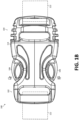
- Figure 1B illustrates a top plan view of a connected buckle assembly 100
- the buckle assembly 100 is configured as a side-release buckle assembly that includes a male buckle component 104 and a female buckle component 102.
- the pair of lateral arm members 116 is inserted into and received by a pocket 128 of female buckle component 102 to latch the buckle assembly 100.
- the pair of lateral arm members 116 is inserted via an insertion force 154, which is indicated by Arrow B.
- the buckle assembly 100 is released or disconnected by providing compression forces 152 inwardly from the side as indicated by Arrows A and A'.
- the male buckle component 104 and the female buckle component 102 can be made as individual monolithic structures of plastic formed by injection molding processes, engineered plastic, moldable plastic, computer numerical control (CNC) machining, or the like.
- CNC computer numerical control
- Leads 122 can be attached to each of the male buckle component 104 and the female buckle component 102 so that buckle assembly 100 can be used to secure together opposite ends of a single lead 122 or to secure ends of separate leads 122.
- Example leads 122 include, inter alia, straps ( e.g., backpack straps, belts, etc.), ropes, strips, cordage, or another material to be fastened.
- the leads 122 may be fabricated from, for example, plastic, nylon, leather, fabric, etc.
- each of the male buckle component 104 and the female buckle component 102 may be adjustably positioned along the length of a lead 122.
- male buckle component 104 and/or the female buckle component 102 may be coupled to an item (e.g., bag, belt, garment, etc.) via mechanical fasteners (e.g., snaps, rivets, carabiner clips, etc.), adhesives, etc.
- an item e.g., bag, belt, garment, etc.
- mechanical fasteners e.g., snaps, rivets, carabiner clips, etc.
- the male buckle component 104 is urged into the female buckle component 102 via insertion force 154.
- the female buckle component 102 defines a receiving body or pocket 128.
- the female buckle component 102 includes a housing 114 formed as a set of plates spaced apart and secured at the edges via the sides 144 to form a pocket-like structure to define the pocket 128.
- the sides 144 of the housing 114 are shaped to define button apertures 140 ( e.g., apertures in the sides 144).
- the button apertures 140 are sized and positioned to receive buttons 106 when the male buckle component 104 is fully inserted into the pocket 128 of the female buckle component 102.
- the pocket 128 may further define one or more channels to define a guide way to direct male buckle component 104 straight into female buckle component 102 from an entrance opening 150 to the pocket 128.
- the one or more channels may be formed on, for example, in interior surface of the set of plates 146.
- the one or more channels may be configured to guide the male buckle component 104 via a mating guide beam 138 that outwardly extends from a rigid strut member. For example, using insertion force 154 as indicated by Arrow B, the mating guide beam 138 passes into a mating channel or sleeve formed in the female buckle component 102 in order to assure proper mating alignment.
- the male buckle component 104 includes a pair of lateral arm members 116. While the pair of lateral arm members 116 are illustrated as generally parallel one another, they may be non-parallel. Each of the lateral arm members 116 includes a flexible lateral arm 112 with a button 106 at a distal end 118 thereof. As illustrated, the flexible lateral arms 112 are spaced apart and generally parallel to one another. In some examples, the flexible lateral arm 112 and the buttons 106 are fabricated as a unitary structure. In some examples, the flexible lateral arm 112 and the buttons 106 are distinct components. For example, the buttons 106 may be a solid, rigid button coupled to an end of the flexible lateral arm 112.
- the flexible lateral arm 112 may be configured to form a non-linear portion that defines, or otherwise serves as, the button 106.
- the flexible lateral arm 112 may be shaped to define the button 106.
- the buttons 106 define a latching ledge 132 configured to engage the female buckle component 102.
- the latching ledge 132 may engage a lock ledge 148 defined by the housing 114 of the female buckle component 102.
- a rigid strut member 108 extends between the lateral arm members 116.
- the rigid strut member 108 is generally perpendicular to the lateral arm members 116.
- a lead-receiving channel 120 is formed through the male buckle component 104 between, for example, the rigid strut member 108 and a lead bar 110.
- the male component 104 may include two or more lead bars 110.
- a lead-receiving channel 120 may be formed between each of the two or more lead bars 110 and/or between the rigid strut member 108 and at least one of the lead bars 110.
- the rigid strut member 108 and the lead bars 110 are parallel to one another.
- the lead-receiving channel 120 is configured to secure the lead 122.
- the lateral arm members 116 are integrally connected to the main body 126 at pivot points 124 ( e.g., via one of the rigid strut members 108).
- the lateral arm members 116 are configured to pivot ( e.g., flex) in the direction of Arrows A and A' about pivot points 124 defined by the union of the rigid strut member 108 and the lateral arm members 116.
- the lateral arm members 116 are rigidly coupled at pivot points 124 and configured to flex inwardly along their lengths ( e.g. , their effective lengths 130) in the direction of Arrows A and A'.
- the rigid strut member 108 is disposed between the pivot points 124 and adjacent the lead-receiving channel 120.
- the pivot points 124 are distally located from the lead bar 110 and the rigid strut member 108.
- a rigid strut member 108 extends between the lateral arm members 116 and is integrally connected with the lead bar 110 to form a main body 126 of the male buckle component 104.
- the rigid strut member 108 is inflexible. While the main body 126 is illustrated with a rigid strut member 108, the rigid strut member 108 may be omitted and the lateral arm members 116 can be integrally connected to the main body 126 at another location. For example, the lateral arm members 116 can be connected at the lead bar 110.
- the pair of lateral arm members 116 is inserted into and received by pocket 128 of female buckle component 102 as indicated by Arrow B to connect the buckle assembly 100.
- the male buckle component 104 is urged into the female buckle component 102 in the direction of Arrow B.
- the mating guide beam 138 of the male buckle component 104 moves into a reciprocal channel formed in the pocket 128 of the female buckle component 102 to ensure proper mating alignment between the female and male buckle components 102 and 104, respectively.
- the lateral arm members 116 deflect inwardly (e.g ., deformed or flexed) in the directions of Arrows A and A' until the buttons 106 reach button apertures 140 formed by the female buckle component 102.
- the flexible lateral arm 112 is configured to flex along its effective length 130 between the pivot point 124 and a latching ledge 132 at its distal end 118.
- the effective length 130 refers to the length along the flexible lateral arm 112 to enable the flexible lateral arm 112 to flex between the pivot point 124 and the distal latching ledge 132 during connecting and disconnecting of the buckle assembly 100.
- the effective length 130 is a function of the shape of the flexible lateral arm 112.
- the flexible lateral arms 112 are generally linear ( e.g. , straight) with a rigid button 106 coupled at the distal end 118 that defines the latching ledge 132.
- buttons 106 When the buttons 106 enter the button apertures 140 in response to the insertion force 154, the tension stored in the lateral arm members 116 (via the flexible lateral arm 112) biases the buttons 106 laterally outward ( e.g ., in directions opposite that of Arrows A and A') such that the buttons 106 are secured within the button apertures 140. At this point, the male buckle component 104 is secured to the female buckle component 102.
- Figure 1B illustrates a top plan view of the buckle assembly 100 in which the male buckle component 104 is securely mated into the female buckle component 102.
- the buttons 106 are squeezed inwardly ( e.g ., from the sides) toward one another in the direction of Arrows A and A'.
- the buckle assembly 100 disclosed herein meets appropriate safety standards (e.g. , withstanding a minimum load and disconnecting upon a maximum load) without breaking when the maximum load is applied to the buckle.
- the female component 102 includes disengagement apertures in addition to the button apertures 140.
- Figure 2A illustrates a disconnected buckle assembly with a female buckle component 102 including disengagement apertures 156 in accordance with aspects of this disclosure.
- Figures 2A and 2B are described with respect to a single button aperture 140 and a single disengagement aperture 156. It should be noted that the following description of the button aperture 140 and the disengagement aperture 156 applies to the buckle assembly 100 as a whole, including a button aperture 140 and a disengagement aperture 156 on each side of the female component 102 ( e.g., the buckle assembly 100 having two button apertures 140 and two disengagement apertures 156).
- the button aperture 140 may be the same or substantially the same as described with respect to Figures 1A and 1B .
- the button aperture 140 may be any suitable shape such that button 106 of the male component 104 can be snapably secured within button aperture 140.
- the button aperture 140 may have a shape that substantially corresponds to the shape of the button 106 of the male component 104.
- the button aperture 140 may define a first width W1 ( e.g., as measured in the direction of the length of the female component 102 from a first proximal end 140a of the button aperture 140 to a first distal end 140b of the button aperture 140).
- the first width W1 may be measured at the widest cross-section of button aperture 140 ( e.g., as measured in the direction of the length of the female component 102).
- the button aperture 140 may also define a first height H1 ( e.g., as measured in a direction generally perpendicular to the first width W1).
- the first height H1 may be measured at the longest cross-section of button aperture 140 ( e.g., as measured in a direction generally perpendicular to the first width W1).
- the housing 114 of the female component 102 includes one or more lock ledges 148 to interface with the male buckle component 104.
- the housing 114 may define the lock ledge 148 at or near the proximal end 140a of the button aperture 140.
- the lock ledge 148 may be located on a different part of the housing 114.
- the female component 102 also includes a disengagement aperture 156. Similar to the button aperture 140, the disengagement aperture 156 may define a second width W2 ( e.g., as measured in the direction of the length of the female component 102 from a second proximal end 156a of the disengagement aperture 156 to a second distal end 156b of the disengagement aperture 156). In some examples, the second width W2 may be measured at the widest cross-section of disengagement aperture 156 ( e.g., as measured in the direction of the length of the female component 102). The disengagement aperture 156 may also define a second height H2 ( e.g., as measured in a direction generally perpendicular to the second width W2). In some examples, the second height H2 may be measured at the longest cross-section of disengagement aperture 156 ( e.g., as measured in a direction generally perpendicular to the second width W2).
- the first height H1 of the button aperture 140 may be larger than the second height H2 of the disengagement aperture 156. Such a configuration may enable the button 106 to be urged into the button aperture 140 without becoming engaged in the disengagement aperture 156.
- the second height H2 of disengagement aperture 156 may be too small for the button 106 to become snapably secured in the disengagement opening 156. In this way, upon insertion force 154, the button 106 will not be biased laterally outward ( e.g ., in directions opposite that of arrows A and A') until the button 106 reaches the button aperture 140.
- the first height H1 of the button aperture 140 may be the same size or smaller than the second height H2 of the disengagement aperture 156.
- the button aperture 140 and the disengagement aperture 156 may be contiguous.
- the distal end 156b of disengagement aperture 156 may abut the proximal end 140a of the button aperture 140.
- the button aperture 140 and disengagement aperture 156 may define a single, larger aperture in the housing 114 of the female component 102.
- a center of each of the button aperture 140 and the disengagement aperture 156 may be configured to align.
- a first center axis of button aperture 140 may substantially align with a second center axis of disengagement aperture 156 (e.g., that is generally perpendicular to the second height H2 and located halfway along second height H2).
- the lock ledge 148 defined by the housing 114 may be positioned at or near the distal end 156b of the disengagement aperture 156 ( e.g., in examples in which the lock ledge 148 is at or near the proximal end 140a of the button aperture 140 since the proximal end 140a of the button aperture 140 abuts the distal end 156b of the disengagement aperture 156 in the contiguous examples discussed herein).
- the housing 114 of the female component 102 may be more flexible than a housing 114 in which the button aperture 140 and the disengagement aperture 156 are not contiguous. In any case, however, a housing 114 having both a button aperture 140 and a disengagement aperture 156 may be more flexible than a housing having only a button aperture 140 and not having a disengagement aperture 156. Flexibility can be increased by including features as openings 158 (e.g., holes or slots) in the set of plates 146 (e.g., the top and bottom plates, as illustrated), in the side walls, etc.
- openings 158 e.g., holes or slots
- the increased flexibility of the housing 114 of the female component 102 having both the button aperture 140 and the disengagement aperture 156 may enable the female component to have a longer useful life and prevent breakage of one or both of the female component 102 or the male component 104 of the buckle assembly 100. Moreover, this increased flexibility of the housing 114 may also enable the female component 102 to expand at a lower load relative to a traditional, less flexible female component, thereby allowing the male component 104 to be disconnected from the female component 102 (without user intervention) without breaking or otherwise being damaged.
- a female component 102 with a button aperture 140 and a disengagement aperture 156 that are contiguous may enable the male component 104 and the female component 102 to disconnect without breaking upon application of a maximum force on the buckle assembly 100.
- a particular force on the buckle assembly 100 e.g., such as a maximum force set by a particular safety standard
- the force upon the buckle assembly 100 may cause the female component 102 and the male component 104 to move in generally opposite directions.
- the force upon the buckle assembly may move the male component 104 a direction substantially opposite of the insertion force 154 ( e.g., in the direction opposite of Arrow B).
- the lock ledge 148 at or near the proximal end 156a of the disengagement aperture 156 may exert a force on the latching ledge 132 that causes the button 106 to be biased laterally inward ( e.g ., in directions of arrows A and A'). This may result in the button 106 of the male component 104 expanding the female component 102 to disconnect from the female component 102 without user intervention and without one or both of the male component 104 or the female component 102 breaking.
- the male component may be configured to pull on the female component at an application of a particular force to cause one or both of the female or male components to break in order to unlatch the buckle assembly.
- the increased flexibility of the female component 102 may enable the buckle assembly 100 to remain intact rather than breaking upon application of a relative high load. Moreover, such flexibility of the female component 102 may enable the buckle assembly 100 to be reused many times, even after application of a relatively high force.
- the buckle assembly 100 including the flexible female component 102 may enable the buckle assembly 100 to be used repeatedly even after ten or more applications of a relatively high force.
- the buckle assembly 100 may be able to be reused after ten or more, twenty or more, fifty or more, or one-hundred or more applications of a relatively high force.
- the buckle assembly 100 described herein may be able to be reused despite any number of applications of a relatively high force.
- Figure 2B illustrates a connected buckle assembly with the female buckle component 102 of Figure 2A and a male buckle component 104 in accordance with aspects of this disclosure.
- the latching ledge 132 of the lateral arm member 116 may define a sloped transition from the flexible lateral arm 112 to the button 106.
- the latching ledge 132 may be sloped upward from the pivot point 124 to the button 106 of the lateral arm member 116.
- the sloped latching ledge 132 may define a gradual transition from the shorter ( e.g ., as measured in the direction of first height H1 and second height H2) height of the flexible lateral arm 112 and the longer ( e.g., as measured in the direction of first height H1 and second height H2) button 106 of the lateral arm member 116.
- the latching ledge 132 may define an obtuse angle (e.g., an angle greater than 90°) measured relative to flexible lateral arm 112.
- the latching ledge 132 may define an obtuse angle with an axis substantially parallel to the axis along which the first and second widths W1, W2 are measured. In other examples, the latching ledge 132 may otherwise define a sloped transition from the flexible lateral arm 112 to the button 106.
- the latching ledge 132 may be curved, stepped, or any other appropriate configuration.
- the latching ledge 132 may include more than one face. In such examples, each of the one or more faces may define a sloped transition as described herein.
- a latching ledge 132 on each side of the button 106 may define a sloped transition from the button106 to the respective side of the flexible lateral arm 112.
- the sloped transition comprises a plurality of faces that collectively define a profile ( e.g., shape) of the sloped transition.
- the female component 102 and/or the male component 104 may be less likely to break upon application of a relatively high force upon the buckle assembly 100 in comparison to a buckle assembly in which the lateral arm member 116 does not include such a gradual transition.
- a lateral arm member 116 with a latching ledge 132 that defines a sloped transition as discussed herein may enable the lock ledge 148 of the female component 102 to gradually engage and exert inward force upon the lateral arm member 116. This may also result in the flexible female component 102 expanding to release the male component 104.
- a buckle assembly without a latching ledge defining a sloped transition as discussed herein may experience a relatively sudden increase in force, and when a force is applied to the buckle assembly that moves the female component and the male component in generally opposite directions, which may cause one or both of the female component or the male component of the buckle assembly to break.
- a male component 104 with a latching ledge 132 that defines a sloped transition from the flexible lateral arm 112 to the button 106 may have a longer useful life than other configurations of male components of buckles assemblies. In fact, such a configuration may enable the buckle assembly 100 disclosed herein to be reusable even after application of a relatively high load upon the buckle assembly 100.
- Figure 3A illustrates another view of a disconnected buckle assembly 100 with a male buckle component 104 in accordance with aspects of this disclosure.
- Figure 3B illustrates the disconnected buckle assembly 100 with a female buckle component 102 in accordance with aspects of this disclosure.
- Figure 3C illustrates a connected buckle assembly 100 with the male buckle component 104 illustrated in Figure 3A and the female buckle component 102 illustrated in Figure 3B in accordance with aspects of this disclosure.
- Figures 3A-3C are substantially the same as the buckle assembly 100 described in connection with Figures 1A-2B .
Landscapes
- Buckles (AREA)
Applications Claiming Priority (2)
| Application Number | Priority Date | Filing Date | Title |
|---|---|---|---|
| US202163249432P | 2021-09-28 | 2021-09-28 | |
| US17/879,493 US11786015B2 (en) | 2021-09-28 | 2022-08-02 | Safety release buckle |
Publications (2)
| Publication Number | Publication Date |
|---|---|
| EP4154751A1 true EP4154751A1 (de) | 2023-03-29 |
| EP4154751B1 EP4154751B1 (de) | 2025-07-16 |
Family
ID=83006075
Family Applications (1)
| Application Number | Title | Priority Date | Filing Date |
|---|---|---|---|
| EP22191448.4A Active EP4154751B1 (de) | 2021-09-28 | 2022-08-22 | Sicherheitsauslöseschnalle |
Country Status (2)
| Country | Link |
|---|---|
| US (1) | US11786015B2 (de) |
| EP (1) | EP4154751B1 (de) |
Families Citing this family (6)
| Publication number | Priority date | Publication date | Assignee | Title |
|---|---|---|---|---|
| EP3703594A4 (de) * | 2017-10-31 | 2021-05-05 | Chris Whelan | Stauschlauchklemme |
| USD1080454S1 (en) * | 2022-10-20 | 2025-06-24 | Hangzhou Tianyuan Pet Products Co., Ltd. | Buckle |
| USD1101611S1 (en) * | 2022-11-16 | 2025-11-11 | Arcade Belts, Inc. | Belt buckle |
| USD1104854S1 (en) * | 2023-03-21 | 2025-12-09 | Zedel | Buckle |
| USD1097874S1 (en) * | 2024-09-09 | 2025-10-14 | Dongguan Yihao Intelligent Technology Co., Ltd. | Buckle |
| USD1100737S1 (en) * | 2024-10-07 | 2025-11-04 | Nanjing Lantu Trading Co., Ltd. | Buckle |
Citations (7)
| Publication number | Priority date | Publication date | Assignee | Title |
|---|---|---|---|---|
| US5584105A (en) * | 1996-01-11 | 1996-12-17 | American Cord & Webbing Co., Inc. | Quick disconnect buckle |
| EP1325690A2 (de) * | 2002-01-03 | 2003-07-09 | Illinois Tool Works, Inc. | Befestigungsvorrichtung für Schnallen-Seilklemmen und dergleichen |
| US7302742B2 (en) | 2005-07-20 | 2007-12-04 | Illinois Tool Works Inc | Side-release buckle assembly |
| US8256072B2 (en) | 2006-12-12 | 2012-09-04 | Illinois Tool Works Inc. | Buckle |
| US20130042445A1 (en) * | 2011-08-16 | 2013-02-21 | Jesse Perreault | Anti-Pinch Apparel Closure |
| CN105768364A (zh) * | 2016-03-23 | 2016-07-20 | 苏州乐聚堂电子科技有限公司 | 鞋子连接装置 |
| US10499617B1 (en) * | 2017-04-21 | 2019-12-10 | Yellow Dog Design, Inc. | Buckle |
Family Cites Families (32)
| Publication number | Priority date | Publication date | Assignee | Title |
|---|---|---|---|---|
| GB2117038B (en) | 1982-03-23 | 1985-09-04 | Nippon Notion Kogyo | Buckle |
| JPS6129604U (ja) | 1984-07-27 | 1986-02-22 | 日本ノ−シヨン工業株式会社 | バツクル |
| US5027481A (en) | 1990-11-01 | 1991-07-02 | Illinois Tool Works | Shell buckle |
| USD341105S (en) | 1991-05-17 | 1993-11-09 | Itw Fastex Italia, S.P.A. | Buckle |
| US5203058A (en) | 1992-05-01 | 1993-04-20 | American Cord & Webbing Co., Inc. | Twin buckle for fastening straps and the like |
| USD373747S (en) | 1993-05-14 | 1996-09-17 | National Molding Corporation | Buckle |
| USD349262S (en) | 1993-07-01 | 1994-08-02 | American Cord & Webbing Co., Inc. | Buckle |
| USD405726S (en) | 1996-05-10 | 1999-02-16 | American Cord and Webbing Company | Buckle |
| US5794316A (en) * | 1996-06-24 | 1998-08-18 | National Molding Corp. | Side-release buckle having improved locking feature |
| US5791026A (en) * | 1997-05-30 | 1998-08-11 | National Molding Corporation | Side-release buckle having retaining straps |
| JP2000106915A (ja) * | 1998-09-30 | 2000-04-18 | Ykk Corp | バックル |
| US6226844B1 (en) | 1999-05-26 | 2001-05-08 | Velcro Industries B.V. | Quick release buckles |
| JP4299941B2 (ja) * | 2000-02-10 | 2009-07-22 | 株式会社ニフコ | バックル |
| US6615460B1 (en) | 2002-08-27 | 2003-09-09 | David Baumgarten | Optionally manual or automatic breakaway lanyard buckle |
| JP4148836B2 (ja) | 2002-09-20 | 2008-09-10 | Ykk株式会社 | バックル |
| US7089633B2 (en) | 2004-09-15 | 2006-08-15 | Kim Ging Hui Enterprise Co., Ltd. | Side release buckle |
| US7140082B2 (en) | 2005-01-12 | 2006-11-28 | Button International Co., Ltd. | Side release buckle allowing locking from an angular position |
| USD535912S1 (en) | 2006-02-10 | 2007-01-30 | Illinois Tool Works Inc. | Buckle member |
| USD536279S1 (en) | 2006-06-14 | 2007-02-06 | Illinois Tool Works Inc | Buckle member |
| JP5020004B2 (ja) | 2007-09-05 | 2012-09-05 | Ykk株式会社 | バックル |
| USD576521S1 (en) | 2008-03-07 | 2008-09-09 | Illinois Tool Works Inc. | Side release buckle |
| US8286311B2 (en) * | 2008-10-31 | 2012-10-16 | Jisook Paik | Buckle |
| EP2415365B1 (de) | 2009-03-31 | 2015-07-01 | YKK Corporation | Seitenfreigabeschnalle |
| WO2011039857A1 (ja) | 2009-09-30 | 2011-04-07 | Ykk株式会社 | サイドリリースバックル |
| US8191213B2 (en) | 2010-03-15 | 2012-06-05 | National Molding Llc | Quick release buckle assembly |
| WO2011146718A1 (en) | 2010-05-21 | 2011-11-24 | Bae Systems Specialty Defense Systems Of Pennsylvania, Inc. | Dual release buckle |
| WO2012066615A1 (ja) | 2010-11-15 | 2012-05-24 | Ykk株式会社 | バックル |
| WO2014046973A1 (en) | 2012-09-18 | 2014-03-27 | Illinois Tool Works Inc. | Releasable buckle |
| US11375777B2 (en) * | 2017-09-15 | 2022-07-05 | Ykk Corporation | Side-release buckle |
| US11259604B2 (en) | 2018-07-23 | 2022-03-01 | Illinois Tool Works Inc. | Anti-pinch buckle assembly |
| USD945313S1 (en) | 2020-02-21 | 2022-03-08 | Illinois Tool Works Inc. | Buckle |
| US11185131B1 (en) * | 2020-12-04 | 2021-11-30 | Duraflex Hong Kong Limited | Buckle assembly |
-
2022
- 2022-08-02 US US17/879,493 patent/US11786015B2/en active Active
- 2022-08-22 EP EP22191448.4A patent/EP4154751B1/de active Active
Patent Citations (7)
| Publication number | Priority date | Publication date | Assignee | Title |
|---|---|---|---|---|
| US5584105A (en) * | 1996-01-11 | 1996-12-17 | American Cord & Webbing Co., Inc. | Quick disconnect buckle |
| EP1325690A2 (de) * | 2002-01-03 | 2003-07-09 | Illinois Tool Works, Inc. | Befestigungsvorrichtung für Schnallen-Seilklemmen und dergleichen |
| US7302742B2 (en) | 2005-07-20 | 2007-12-04 | Illinois Tool Works Inc | Side-release buckle assembly |
| US8256072B2 (en) | 2006-12-12 | 2012-09-04 | Illinois Tool Works Inc. | Buckle |
| US20130042445A1 (en) * | 2011-08-16 | 2013-02-21 | Jesse Perreault | Anti-Pinch Apparel Closure |
| CN105768364A (zh) * | 2016-03-23 | 2016-07-20 | 苏州乐聚堂电子科技有限公司 | 鞋子连接装置 |
| US10499617B1 (en) * | 2017-04-21 | 2019-12-10 | Yellow Dog Design, Inc. | Buckle |
Also Published As
| Publication number | Publication date |
|---|---|
| US11786015B2 (en) | 2023-10-17 |
| EP4154751B1 (de) | 2025-07-16 |
| US20230100046A1 (en) | 2023-03-30 |
Similar Documents
| Publication | Publication Date | Title |
|---|---|---|
| EP4154751A1 (de) | Sicherheitsauslöseschnalle | |
| US12220024B2 (en) | Buckle | |
| EP2780656B1 (de) | Vorrichtung und verfahren zum zusammenfügen und freigeben eines kleidungsstücks | |
| US7346965B2 (en) | Side release buckle | |
| US8181318B2 (en) | Buckle assembly | |
| EP2316295B1 (de) | Schnell lösbare Schnallenanordnung | |
| EP2641498B1 (de) | Schnalle | |
| US6076237A (en) | Quick-release buckle for connecting two strap ends | |
| US20060168783A1 (en) | Dual locking buckle | |
| US20120297527A1 (en) | Quick Release Mechanism for Garment | |
| US4631787A (en) | Buckle having manually releasable interlocking male and female portions | |
| EP3827692B1 (de) | Schnalle | |
| CN101511218A (zh) | 带扣结构 | |
| CN105338849B (zh) | 用于把带扣壳体固定到部件的系统和组合件 | |
| US20230413955A1 (en) | Belt buckle | |
| US20240341415A1 (en) | Pinch Resistant Helmet Buckle | |
| US9115959B2 (en) | Quick release garment | |
| CA2438850C (en) | Seatbelt with child resistant buckle | |
| US11533969B2 (en) | Side release buckle | |
| US6154935A (en) | Quick release buckle for use on backpacks and the like | |
| US8464406B2 (en) | Quick release buckle assembly | |
| KR102535675B1 (ko) | 지퍼 체결구 | |
| US20240298753A1 (en) | Buckle | |
| EP4289306A1 (de) | Schnellverschlussclip | |
| CN117122131A (zh) | 带扣 |
Legal Events
| Date | Code | Title | Description |
|---|---|---|---|
| PUAI | Public reference made under article 153(3) epc to a published international application that has entered the european phase |
Free format text: ORIGINAL CODE: 0009012 |
|
| STAA | Information on the status of an ep patent application or granted ep patent |
Free format text: STATUS: THE APPLICATION HAS BEEN PUBLISHED |
|
| AK | Designated contracting states |
Kind code of ref document: A1 Designated state(s): AL AT BE BG CH CY CZ DE DK EE ES FI FR GB GR HR HU IE IS IT LI LT LU LV MC MK MT NL NO PL PT RO RS SE SI SK SM TR |
|
| STAA | Information on the status of an ep patent application or granted ep patent |
Free format text: STATUS: REQUEST FOR EXAMINATION WAS MADE |
|
| 17P | Request for examination filed |
Effective date: 20230929 |
|
| RBV | Designated contracting states (corrected) |
Designated state(s): AL AT BE BG CH CY CZ DE DK EE ES FI FR GB GR HR HU IE IS IT LI LT LU LV MC MK MT NL NO PL PT RO RS SE SI SK SM TR |
|
| STAA | Information on the status of an ep patent application or granted ep patent |
Free format text: STATUS: EXAMINATION IS IN PROGRESS |
|
| 17Q | First examination report despatched |
Effective date: 20240215 |
|
| GRAP | Despatch of communication of intention to grant a patent |
Free format text: ORIGINAL CODE: EPIDOSNIGR1 |
|
| STAA | Information on the status of an ep patent application or granted ep patent |
Free format text: STATUS: GRANT OF PATENT IS INTENDED |
|
| INTG | Intention to grant announced |
Effective date: 20250422 |
|
| RIN1 | Information on inventor provided before grant (corrected) |
Inventor name: KELLER, STEVE Inventor name: PONTAOE, JOHN |
|
| GRAS | Grant fee paid |
Free format text: ORIGINAL CODE: EPIDOSNIGR3 |
|
| GRAA | (expected) grant |
Free format text: ORIGINAL CODE: 0009210 |
|
| STAA | Information on the status of an ep patent application or granted ep patent |
Free format text: STATUS: THE PATENT HAS BEEN GRANTED |
|
| P01 | Opt-out of the competence of the unified patent court (upc) registered |
Free format text: CASE NUMBER: APP_24638/2025 Effective date: 20250522 |
|
| AK | Designated contracting states |
Kind code of ref document: B1 Designated state(s): AL AT BE BG CH CY CZ DE DK EE ES FI FR GB GR HR HU IE IS IT LI LT LU LV MC MK MT NL NO PL PT RO RS SE SI SK SM TR |
|
| REG | Reference to a national code |
Ref country code: GB Ref legal event code: FG4D |
|
| REG | Reference to a national code |
Ref country code: CH Ref legal event code: EP |
|
| REG | Reference to a national code |
Ref country code: DE Ref legal event code: R096 Ref document number: 602022017567 Country of ref document: DE |
|
| REG | Reference to a national code |
Ref country code: IE Ref legal event code: FG4D |
|
| PGFP | Annual fee paid to national office [announced via postgrant information from national office to epo] |
Ref country code: DE Payment date: 20250929 Year of fee payment: 4 |
|
| PGFP | Annual fee paid to national office [announced via postgrant information from national office to epo] |
Ref country code: FR Payment date: 20250925 Year of fee payment: 4 Ref country code: AT Payment date: 20251020 Year of fee payment: 4 |
|
| REG | Reference to a national code |
Ref country code: NL Ref legal event code: MP Effective date: 20250716 |
|
| PG25 | Lapsed in a contracting state [announced via postgrant information from national office to epo] |
Ref country code: PT Free format text: LAPSE BECAUSE OF FAILURE TO SUBMIT A TRANSLATION OF THE DESCRIPTION OR TO PAY THE FEE WITHIN THE PRESCRIBED TIME-LIMIT Effective date: 20251117 |
|
| PG25 | Lapsed in a contracting state [announced via postgrant information from national office to epo] |
Ref country code: NL Free format text: LAPSE BECAUSE OF FAILURE TO SUBMIT A TRANSLATION OF THE DESCRIPTION OR TO PAY THE FEE WITHIN THE PRESCRIBED TIME-LIMIT Effective date: 20250716 |
|
| REG | Reference to a national code |
Ref country code: AT Ref legal event code: MK05 Ref document number: 1813207 Country of ref document: AT Kind code of ref document: T Effective date: 20250716 |
|
| PG25 | Lapsed in a contracting state [announced via postgrant information from national office to epo] |
Ref country code: IS Free format text: LAPSE BECAUSE OF FAILURE TO SUBMIT A TRANSLATION OF THE DESCRIPTION OR TO PAY THE FEE WITHIN THE PRESCRIBED TIME-LIMIT Effective date: 20251116 |
|
| PG25 | Lapsed in a contracting state [announced via postgrant information from national office to epo] |
Ref country code: NO Free format text: LAPSE BECAUSE OF FAILURE TO SUBMIT A TRANSLATION OF THE DESCRIPTION OR TO PAY THE FEE WITHIN THE PRESCRIBED TIME-LIMIT Effective date: 20251016 |
|
| REG | Reference to a national code |
Ref country code: LT Ref legal event code: MG9D |
|
| PG25 | Lapsed in a contracting state [announced via postgrant information from national office to epo] |
Ref country code: AT Free format text: LAPSE BECAUSE OF FAILURE TO SUBMIT A TRANSLATION OF THE DESCRIPTION OR TO PAY THE FEE WITHIN THE PRESCRIBED TIME-LIMIT Effective date: 20250716 |
|
| PG25 | Lapsed in a contracting state [announced via postgrant information from national office to epo] |
Ref country code: FI Free format text: LAPSE BECAUSE OF FAILURE TO SUBMIT A TRANSLATION OF THE DESCRIPTION OR TO PAY THE FEE WITHIN THE PRESCRIBED TIME-LIMIT Effective date: 20250716 |
|
| PG25 | Lapsed in a contracting state [announced via postgrant information from national office to epo] |
Ref country code: HR Free format text: LAPSE BECAUSE OF FAILURE TO SUBMIT A TRANSLATION OF THE DESCRIPTION OR TO PAY THE FEE WITHIN THE PRESCRIBED TIME-LIMIT Effective date: 20250716 |
|
| PG25 | Lapsed in a contracting state [announced via postgrant information from national office to epo] |
Ref country code: GR Free format text: LAPSE BECAUSE OF FAILURE TO SUBMIT A TRANSLATION OF THE DESCRIPTION OR TO PAY THE FEE WITHIN THE PRESCRIBED TIME-LIMIT Effective date: 20251017 |
|
| PG25 | Lapsed in a contracting state [announced via postgrant information from national office to epo] |
Ref country code: SE Free format text: LAPSE BECAUSE OF FAILURE TO SUBMIT A TRANSLATION OF THE DESCRIPTION OR TO PAY THE FEE WITHIN THE PRESCRIBED TIME-LIMIT Effective date: 20250716 |
|
| PG25 | Lapsed in a contracting state [announced via postgrant information from national office to epo] |
Ref country code: LV Free format text: LAPSE BECAUSE OF FAILURE TO SUBMIT A TRANSLATION OF THE DESCRIPTION OR TO PAY THE FEE WITHIN THE PRESCRIBED TIME-LIMIT Effective date: 20250716 |
|
| PG25 | Lapsed in a contracting state [announced via postgrant information from national office to epo] |
Ref country code: PL Free format text: LAPSE BECAUSE OF FAILURE TO SUBMIT A TRANSLATION OF THE DESCRIPTION OR TO PAY THE FEE WITHIN THE PRESCRIBED TIME-LIMIT Effective date: 20250716 Ref country code: BG Free format text: LAPSE BECAUSE OF FAILURE TO SUBMIT A TRANSLATION OF THE DESCRIPTION OR TO PAY THE FEE WITHIN THE PRESCRIBED TIME-LIMIT Effective date: 20250716 |
|
| PG25 | Lapsed in a contracting state [announced via postgrant information from national office to epo] |
Ref country code: RS Free format text: LAPSE BECAUSE OF FAILURE TO SUBMIT A TRANSLATION OF THE DESCRIPTION OR TO PAY THE FEE WITHIN THE PRESCRIBED TIME-LIMIT Effective date: 20251016 |
|
| PG25 | Lapsed in a contracting state [announced via postgrant information from national office to epo] |
Ref country code: ES Free format text: LAPSE BECAUSE OF FAILURE TO SUBMIT A TRANSLATION OF THE DESCRIPTION OR TO PAY THE FEE WITHIN THE PRESCRIBED TIME-LIMIT Effective date: 20250716 |
|
| PG25 | Lapsed in a contracting state [announced via postgrant information from national office to epo] |
Ref country code: RO Free format text: LAPSE BECAUSE OF FAILURE TO SUBMIT A TRANSLATION OF THE DESCRIPTION OR TO PAY THE FEE WITHIN THE PRESCRIBED TIME-LIMIT Effective date: 20250716 |
|
| REG | Reference to a national code |
Ref country code: CH Ref legal event code: H13 Free format text: ST27 STATUS EVENT CODE: U-0-0-H10-H13 (AS PROVIDED BY THE NATIONAL OFFICE) Effective date: 20260324 |
|
| PG25 | Lapsed in a contracting state [announced via postgrant information from national office to epo] |
Ref country code: SM Free format text: LAPSE BECAUSE OF FAILURE TO SUBMIT A TRANSLATION OF THE DESCRIPTION OR TO PAY THE FEE WITHIN THE PRESCRIBED TIME-LIMIT Effective date: 20250716 |
|
| PG25 | Lapsed in a contracting state [announced via postgrant information from national office to epo] |
Ref country code: DK Free format text: LAPSE BECAUSE OF FAILURE TO SUBMIT A TRANSLATION OF THE DESCRIPTION OR TO PAY THE FEE WITHIN THE PRESCRIBED TIME-LIMIT Effective date: 20250716 |
|
| PG25 | Lapsed in a contracting state [announced via postgrant information from national office to epo] |
Ref country code: LU Free format text: LAPSE BECAUSE OF NON-PAYMENT OF DUE FEES Effective date: 20250822 Ref country code: IT Free format text: LAPSE BECAUSE OF FAILURE TO SUBMIT A TRANSLATION OF THE DESCRIPTION OR TO PAY THE FEE WITHIN THE PRESCRIBED TIME-LIMIT Effective date: 20250716 |
|
| PG25 | Lapsed in a contracting state [announced via postgrant information from national office to epo] |
Ref country code: CH Free format text: LAPSE BECAUSE OF NON-PAYMENT OF DUE FEES Effective date: 20250831 Ref country code: CZ Free format text: LAPSE BECAUSE OF FAILURE TO SUBMIT A TRANSLATION OF THE DESCRIPTION OR TO PAY THE FEE WITHIN THE PRESCRIBED TIME-LIMIT Effective date: 20250716 |
|
| PG25 | Lapsed in a contracting state [announced via postgrant information from national office to epo] |
Ref country code: SK Free format text: LAPSE BECAUSE OF FAILURE TO SUBMIT A TRANSLATION OF THE DESCRIPTION OR TO PAY THE FEE WITHIN THE PRESCRIBED TIME-LIMIT Effective date: 20250716 Ref country code: EE Free format text: LAPSE BECAUSE OF FAILURE TO SUBMIT A TRANSLATION OF THE DESCRIPTION OR TO PAY THE FEE WITHIN THE PRESCRIBED TIME-LIMIT Effective date: 20250716 |