EP4154641B1 - Latenzreduktionsverfahren für steuerkanaldecodierung - Google Patents
Latenzreduktionsverfahren für steuerkanaldecodierung Download PDFInfo
- Publication number
- EP4154641B1 EP4154641B1 EP21853387.5A EP21853387A EP4154641B1 EP 4154641 B1 EP4154641 B1 EP 4154641B1 EP 21853387 A EP21853387 A EP 21853387A EP 4154641 B1 EP4154641 B1 EP 4154641B1
- Authority
- EP
- European Patent Office
- Prior art keywords
- dci
- cces
- aggregation level
- per
- decoding
- Prior art date
- Legal status (The legal status is an assumption and is not a legal conclusion. Google has not performed a legal analysis and makes no representation as to the accuracy of the status listed.)
- Active
Links
Images


Classifications
-
- H—ELECTRICITY
- H04—ELECTRIC COMMUNICATION TECHNIQUE
- H04W—WIRELESS COMMUNICATION NETWORKS
- H04W72/00—Local resource management
- H04W72/04—Wireless resource allocation
- H04W72/044—Wireless resource allocation based on the type of the allocated resource
- H04W72/0453—Resources in frequency domain, e.g. a carrier in FDMA
-
- H—ELECTRICITY
- H04—ELECTRIC COMMUNICATION TECHNIQUE
- H04L—TRANSMISSION OF DIGITAL INFORMATION, e.g. TELEGRAPHIC COMMUNICATION
- H04L1/00—Arrangements for detecting or preventing errors in the information received
- H04L1/004—Arrangements for detecting or preventing errors in the information received by using forward error control
- H04L1/0056—Systems characterized by the type of code used
- H04L1/0061—Error detection codes
-
- H—ELECTRICITY
- H04—ELECTRIC COMMUNICATION TECHNIQUE
- H04L—TRANSMISSION OF DIGITAL INFORMATION, e.g. TELEGRAPHIC COMMUNICATION
- H04L5/00—Arrangements affording multiple use of the transmission path
- H04L5/003—Arrangements for allocating sub-channels of the transmission path
- H04L5/0053—Allocation of signalling, i.e. of overhead other than pilot signals
-
- H—ELECTRICITY
- H04—ELECTRIC COMMUNICATION TECHNIQUE
- H04W—WIRELESS COMMUNICATION NETWORKS
- H04W24/00—Supervisory, monitoring or testing arrangements
- H04W24/10—Scheduling measurement reports ; Arrangements for measurement reports
-
- H—ELECTRICITY
- H04—ELECTRIC COMMUNICATION TECHNIQUE
- H04W—WIRELESS COMMUNICATION NETWORKS
- H04W72/00—Local resource management
- H04W72/20—Control channels or signalling for resource management
- H04W72/23—Control channels or signalling for resource management in the downlink direction of a wireless link, i.e. towards a terminal
-
- H—ELECTRICITY
- H04—ELECTRIC COMMUNICATION TECHNIQUE
- H04W—WIRELESS COMMUNICATION NETWORKS
- H04W72/00—Local resource management
- H04W72/50—Allocation or scheduling criteria for wireless resources
- H04W72/54—Allocation or scheduling criteria for wireless resources based on quality criteria
- H04W72/541—Allocation or scheduling criteria for wireless resources based on quality criteria using the level of interference
-
- H—ELECTRICITY
- H04—ELECTRIC COMMUNICATION TECHNIQUE
- H04L—TRANSMISSION OF DIGITAL INFORMATION, e.g. TELEGRAPHIC COMMUNICATION
- H04L5/00—Arrangements affording multiple use of the transmission path
- H04L5/003—Arrangements for allocating sub-channels of the transmission path
- H04L5/0058—Allocation criteria
- H04L5/006—Quality of the received signal, e.g. BER, SNR, water filling
Definitions
- the disclosed techniques relate to latency reducing techniques for a network device, more particularly, to latency reducing techniques for decoding a control channel at a network device, and further particularly, to a method for reducing latency and a system.
- the communications are generally coded prior to transmission.
- the data in coded formats with header information that can help the recipient decode the data upon receipt.
- the recipient e.g., a terminal device
- the information needed to decode the coded values is within the signal.
- the information needed for decoding is called the downlink control information (DCI), which is conveyed in PDCCH (Physical Downlink Control Channel) channel.
- DCI can be transmitted on multiple control channel elements (CCEs) within a signal.
- CCEs control channel elements
- the method used to find the information is a brute-force approach. More specifically, the recipient can search one-by-one in a first come-first search basis. In other words, the recipient decodes and reads each resource block, in a linear fashion, until the DCI is found.
- US 2009/0088148 A1 discloses a method of monitoring a physical downlink control channel (PDCCH) in a wireless communication system.
- PDCCH physical downlink control channel
- US 10,271,321 B1 discloses a method and apparatus that enable a UE to reduce the total number of decoding attempts without missing any PDCCH candidates that may be addressed to the UE which in turn may reduce the power consumption and may reduce the probability of false DCI detection.
- WO 2017/001025 A1 discloses a receiver device.
- the receiver device comprises a receiver configured to receive a communication signal (CS) in a current time frame; a processor configured to: determine a set of candidate Control Channels, (CCHs), wherein each candidate CCH in the set is addressed for another receiver device and associated with a Data Channel (DCH), of the communication signal (CS); determine a decoding order for the candidate CCHs in the set; decode at least one candidate CCH in the set according to the decoding order; compute a possible Radio Network Temporary Identifier (RNTI), for the decoded candidate CCH; compute a metric value (MV) for the decoded candidate CCH, the metric value (MV) providing an indication if the decoded candidate CCH might be an actual CCH; determine if the decoded candidate CCH is an actual CCH based on the computed possible RNTI and the metric value (MV); derive control information (CI) from the decoded candidate CCH if the decoded candidate
- US 2012/0294271 A1 discloses a mobile station capable of efficiently detecting control information addressed thereto, by prioritizing CRC decoding to control channel element at a candidate position.
- Telecommunication systems require recipients of signals to decode the values within the signal.
- Each signal can carry multiple types of data such as control data and user data. Due to this, the recipient of the signal has to decode each signal to determine the pieces of the data that apply to certain situations. For instance, certain data might provide instructions to the recipient on how to decode the remaining data. Other data may provide details regarding the sequence at which the recipient should read the data. As such, decoding the signal is a primary task of a recipient.
- DCI can also be used by a network to, for example, instruct a terminal to perform an uplink transmission, or adjust timing or power of a communication. Therefore, due to the variability of instructions, the bit length of information in a DCI is also variable. Another factor is the signal to noise ratio (SNR).
- SNR signal to noise ratio
- the SNR of the received signal at a terminal can be low or high. When SNR of the received signal at a terminal is high, the network needs fewer resources (e.g., CCE with a smaller aggregation level) to transmit DCI. When the SNR is low, the network needs more resources (e.g., CCE with a larger aggregation level) to transmit DCI.
- the resource range for a network to send the DCI is large.
- the terminal usually, knows the DCI range, the terminal does not know whether the network sends the DCI or not, in which specific resources the DCI is sent, and which DCI format the network sends the DCI, if at all.
- the common approach is a linear search of CCEs with all possible sizes as they are received. In other words, a terminal device searches one-by-one until the CCEs with the DCI is found. This linear search causes multiple issues. A few of the multiple issues are described below.
- the linear search technique uses more power than is necessary. Due to the nature of a linear search, there are situations where the DCI is found in the first hypothesis (with certain combination of CCEs) that is decoded. However, there are also situations where the DCI is found in the last hypothesis (with another combination of CCEs) that is decoded. As one can imagine, the inherent nature of the linear search leads to the assumption that, on average, the DCI is found in the hypothesis that is in the middle of the first and last hypothesis. In any case, the power consumption also varies with where the DCI is found. Given that power consumption is a primary factor in the design of terminal device, the power consumption for finding the DCI must also be optimized.
- a terminal device has limited capacity and computing capability, and thus, the limited resources need to be used efficiently.
- the linear search for the DCI uses the limited capabilities, which can be applied to other tasks.
- a terminal device may need allot computing capabilities for finding the DCI irrespective of whether the DCI is found in the first hypothesis or last hypothesis because the terminal device needs to allot resources for the worst-case scenario. Due to this, the allotted computed resources can be more efficiently used.
- the linear search causes latency; in particular, DCI detection latency. This is especially problematic in situations where the terminal device is communicating on multiple carriers. Large DCI detection latency leads to other consequences such as larger buffer sizes. Larger buffer size requirements, in turn, leads to more hardware space being used. Further, DCI detection latency leads to a poor user experience. For instance, in an autonomous driving car, the car is expected to process information and directions in near- real-time. If there is DCI latency, the car may not process information as quickly as it should, which may lead to emergency situations. As such, the linear search can cause issues in the design of the terminal device and in application.
- the technique includes determining a probability that a DCI is transmitted at a given aggregation level.
- the probability is dependent on the packet error rate (PER).
- the PER can depend on factors such as the signal to noise ratio (SNR) and fading measurements (e.g., fading channel).
- SNR signal to noise ratio
- the probability can depend on the reception history of the terminal device.
- the logic behind technique can be based on the principle that distance from the base station effects the PER and thus, the probability of DCI being transmitted at each aggregation level. If the terminal device is close to the base station, the SNR is likely to be high.
- the DCI is more likely to be transmitted at lower aggregation levels. This is because, at low SNR values, the base station can send DCI without having to send multiple copies to accommodate for noise. Similar logic can be applied to the fading measurements. Fading measurements can be affected by factors such as the Doppler shift and frequency selectivity. For example, if a PDCCH is transmitted with a high error rate due to Doppler shift, the terminal can determine that it is more likely that the DCI is transmitted with a high aggregation level.
- past reception history can help determine the probability that a base station transmits DCI at a particular aggregation level. For instance, the reception history may indicate that a majority of the DCI was previously transmitted at aggregation level 4. Thus, the terminal can determine that CCE with aggregation level 4 are more likely to be carrying the DCI, than other CCEs. In this manner, the technique addresses the issues described above and others by efficiently determining where the DCI is located.
- a terminal device e.g., mobile device
- receiver e.g., a cellular phone
- a technique for locating the DCI can apply a technique for locating the DCI.
- the techniques disclosed here are not limited to applicability to terminal devices, receivers, or to any other particular kind of devices.
- Other device for example, electronic device or systems (e.g., base stations) may adapt the techniques in a similar manner.
- DCI downlink control information
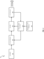
- Fig. 1 illustrates a high level block diagram 100 of the components of a receiver.
- Diagram 100 includes LLR buffer 102, de-rate matcher 104, decoder 106, error detector 108, blinding decoding controller 110, and aggregation level predictor 112. The output from these components and the techniques that are applied between the components results in the DCI output to another component of the receiver (e.g., terminal device).
- the LLR buffer 102 can be programmed to store LLRs.
- the LLR buffer 102 can store the LLR values for each aggregation level.
- the LLR buffer 102 can receive input from a processor (not shown in Fig. 1 ).
- the de-rate matcher 104 receives input from the LLR buffer 102 according to the CCE location. Further, the de-rate matcher 104 receives input from the blind decoding controller 110 (described below). Generally, the de-rate matcher 104 can receive instructions regarding which CCEs to decode from the blind decoding controller 110. Based on the instructions, the de-rate matcher 104 can pull the LLR information for the CCE from the LLR buffer 102. For example, the blind decoding controller 110 can indicate that a given set of CCEs can be decoded. In response, the de-rate matcher 104 can pull the LLRs for the set of CCEs.
- the decoder 106 can decode the CCE to retrieve the DCI.
- the decoder 106 can receive inputs from the de-rate matcher 104 and the blind decoding controller 110.
- the decoder 106 can apply various decoding techniques depending on the technology that the receiver is using. For example, the decoder 106 can use Viterbi decoding techniques for Long Term Evolution (LTE) and Polar decoding for new radio (NR).
- LTE Long Term Evolution
- NR Polar decoding for new radio
- the decoder 106 can comprise multiple sub-decoders that each apply a different decoding technique.
- the decoder 106 can also include a decision module which is configured to stream CCEs to the appropriate sub-decoder.
- the decoder 106 can include a sub-decoder that applies only Viterbi techniques and another sub-decoder that applies only Polar decoding techniques.
- the decision module can, then, based on the current technology, direct data to the appropriate sub-decoder.
- the decoder 106 can output to the error detector 108.
- the error detector 108 can determine if the decoded DCI is a valid DCI. To do so, the error detector 108 can perform error detection on each result from the decoder 106. The error detector 108 can apply known error checks such as cyclic redundancy checks (CRC), decoding metric checks, and/or DCI field validness checks. If the error detector 108 determines that the decoded DCI does have an error, the decoded DCI can be discarded. Upon discarding, the error detector 108 can indicate to the blind decoding controller 120 that further decoded is required. In some cases, the error detector 108 can move on the next decoded DCI. If the decoded DCI is valid, the error detector 108 can output the DCI for receipt by another component of the receiver. In some embodiments, the valid DCI can also be output to the blind decoding controller 110, as explained below.
- the blind decoding controller 110 can receive input from the aggregation level predictor 112.
- the aggregation level predictor 112 can perform techniques to determine the probability of each aggregation level of the DCI to be detected. Based on the probability, the aggregation level predictor 112 can instruct the blind decoding controller 110 to provide instructions to the de-rate matcher 104 and decoder 106 to decode CCE(s) based on the probabilities. For instance, the decoding can be done in descending order of probability. The CCE(s) with the aggregation level corresponding to the highest probability of having the DCI can be decoded first. Subsequently, the CCEs with the aggregation level corresponding to the second highest can be decoded. The decoding can be done in this descending manner until the DCI is found.
- the probability of a DCI being transmitting with an aggregation level can depend on the packet error rate (PER).
- PER can be affected by factors such as the signal to noise ratio (SNR) and/or the fading measurements.
- SNR signal to noise ratio
- the probability can be affected by the reception history. Determining the probability based on SNR can be dependent on the principle that the (PER) and SNR are inversely proportional.
- the transmitter e.g., base station
- the transmitter can be aware of the terminal's SNR from terminal's channel state information feedback. When the terminal's SNR is low, the transmitter (e.g., base station) sends multiple copies of the DCI. The transmitter does this to better ensure that the receiver can piece together the entire signal, even when certain packets are lost during transmission or includes incorrect bits.
- SNR is generally high when the distance between the transmitter and receiver is low. This is because it is less likely that noise can interfere with a signal when the transmission distance is low.
- a receiver can determine whether a PER is high or low. Based on the PER, subsequently, the receiver can also determine whether multiple copies of the DCI were likely transmitted.
- the transmitter can use a higher aggregation level.
- the transmitter may increase the aggregation level when sending multiple copies (e.g., more symbols).
- a base station can be far enough away from the receiver that the base station can determine to send three copies of DCI information that is 90 bits.
- the transmission includes 270 bits of DCI information.
- the transmission can occur over a QPSK technology, which permits each resource element to include two bits.
- the aggregation level is at least two.
- the receiver may not be aware of the details mentioned above. However, the receiver can, for example, based on the distance from the base station and, determine that the SNR is likely to be low, which indicates that the PER is likely to the high. Further, rather than derive the SNR from other values (e.g., distance from the base station), the receiver can include capabilities to measure the SNR of a given signal. For example, upon receipt, the receiver can measure the SNR the signal and information the aggregation level predictor 112.
- the aggregation level predictor 112 can predict the probability of each aggregation level carrying the DCI. In the example above, the aggregation level predictor 112 can determine that aggregation level 4 has the highest probability, with aggregation levels 8, 2, and 1 begin the next highest probable, in order. The aggregation level predictor 112 can instruct the blind decoding controller 110 to decode CCE with the aggregation level 4 first, then 8, then 2, and lastly, 1.
- the probability of an aggregation level carrying a DCI based on PER can be calculated as follows.
- the target PER can be denoted as: per t arg et .
- the SNR-to-PER relationship for each aggregation level can be determined based on curve p al ( snr ) .
- the receiver map the measured SNR value on the curve to determine the likely aggregation level of the signal corresponding to the measured SNR value.
- the fading measurements can be affected by factors such as Doppler shift or delay spread. Similar to SNR, the relationship between PER and the fading measurements can help determine the probabilities of each aggregation level carrying the DCI. For example, the PER can increase due to occurrences of Doppler shift. Thus, the aggregation level predictor 112 can determine higher probabilities for the higher aggregation levels.
- the aggregation level predictor 112 can use both the fading measurements and the SNR measurement to determine a probability. For instance, the aggregation level predictor 112 can determine that a fading measurement can offset the SNR by a delta, ⁇ .
- yet another factor that can help determine the probability is the reception history of the receiver.
- the reception history can be based on the communication between the receiver and a particular transmitter, based on all the communication that the receiver has received, based on the distance between the receiver and the transmitter, or other such categories.
- the general principle being that the aggregation level predictor 112 can determine probabilities based on the previous reception history of the terminal device. For example, if the receiver has previously received 60% of the received DCI at aggregation level 4, and 20% at aggregation level 2, and another 20% at aggregation level 8, then the probabilities can reflect this reception history.
- the aggregation level predictor 112 can determine that at the current between the receiver and transmitter at which the signal was received, the receiver previously received DCI at aggregation level 4 a majority of the time. Thus, the probabilities can reflect this reception history.
- the reception history can be categorized based on the SNR.
- an SNR range can be divided into M+1 bins, as in: ( ⁇ ,SNR 1 ] , ( SNR 1 , SNR 2 ],...,( SNR M- 1 , SNR M ],( SNR M -1 ,+ ⁇ ).
- the SNR of a signal can be measured as "snr".
- the "snr" value can then be placed in the right bin, where SNR m -1 ⁇ snr ⁇ SNR m. From this placement, the aggregation level predictor 112 can determine the probabilities.
- the aggregation level predictor 112 can determine whether the number of valid DCI collected with SNR within the range of the bin surpasses a predetermined threshold value. If the number of valid DCI does surpass the predetermined threshold, the aggregation level predictor 112 can determine the probability based on the reception history. If the number of valid DCI is lower than the predetermined threshold value, the aggregation level predictor 112 can apply one of the other techniques mentioned above (e.g., fading measurement).
- the receiver can decode CCE is an order that is based on the probability of DCI being transmitted with a given aggregation level.
- the probability can be based on the PER, which can be affected by factors such as the SNR, fading measurements, and reception history.
- Fig. 2A illustrates an example 200 of control channel elements (CCEs) being received during a time period.
- the example 200 includes CCEs 206, 208, 210, 212, 214, and 216 that are using corresponding aggregation levels (ALs).
- the receiver can receive an AL2 hypothesis with CCE 7 and CCE 8 first, then AL2 hypothesis with CCE 5 and CCE 6, then an AL2 hypothesis with CCE 3 and CCE 4, then an AL2 hypothesis with CCE 1 and CCE 2, then an AL4 hypothesis with CCEs 9-12, then an AL4 hypothesis with CCEs 1-4, and so on until all AL and corresponding CCEs are received.
- a CEE can be used in different hypotheses with different ALs.
- a receiver can receive an AL2 hypothesis with CCE1-4, as in 210 and 212, and also with AL4, as in 206.
- the time for receipt can range between T 0 and T N .
- Figs. 2A-C are merely examples to illustrate the technology described herein.
- an AL can indicate the number of CCEs that are allocated per PDCCH.
- an AL4 represents a group of 4 CCEs allocated to a PDCCH, as depicted in Fig. 2A .
- the relationship between AL and the number of CCEs is shown in Table 1 below: Table 1 Aggregation Level (AL) Number of CCEs 1 1 2 2 4 4 8 8 16 16
- Fig. 2B illustrates an example of the order 202 that the CCEs received in example 200 are decoded.
- a system e.g., the aggregation level predictor 112 may have determined the probability for each aggregation level and ordered the aggregation levels in descending order. The system can then instruct the decoder 218 to decode the CCEs based on the aggregation level order.
- the AL 2 is determined to have a higher probability of carrying the DCI than AL 4.
- the decoder 218 decodes the CCEs using AL 2 first.
- 210, 212, 214 and 216 are using AL 2.
- the decoder 218 and/or other system e.g., aggregation level predictor 112 can determine that the CCEs can be decoded in the order that they were received.
- the system can perform additional checks on CCEs using the same aggregation levels. For instance, the system can determine the fading channel for 214 and 216. Based on the fading channel, the order in which they are decoded can be determined. In Fig. 2B , for example, CCE 216 may have been received first, and thus, can be decoded prior to CCE 214.
- the remaining CCEs may not be decoded. For instance, in Fig. 2B , if the DCI is found in the CCEs 216, the remaining CCEs may not decoded.
- the determination to continue decoding can depend on the aggregation level. For example, in AL 2, the system can know that the DCI is segmented over at least two CCEs. Thus, multiple CCEs using AL 2 can be decoded. In Fig. 2B , for example, if the DCI is found in the CCEs 216, the system can continue decoding CCEs using AL 2 until all hypotheses are decoded and obtained.
- Fig. 2C illustrates another example 204 of the order that the CCEs are decoded.
- AL 4 has a higher probability than AL 2 of carrying the DCI.
- the decoder 218 decodes the CCEs based on the probability.
- the system can determine, for example, which CCE was received first. Based on this determination, the CCEs using the same aggregation levels can be decoded.
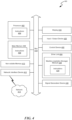
- Fig. 3 is a flowchart that illustrates a method 300 for decoding CCEs.
- the method 300 includes block 302, 304, and 306. Further, the method 300 can optionally include block 308 and 310.
- the method 300 can be applied by a terminal device such as mobile device (e.g., an iPhone) operating on New Radio (NR) technology or Long Term Evolution (LTE) technology.
- the terminal device can include a receiver to receive signals from a network node such as base station.
- the terminal device can also include a processor to perform at least some of the techniques described here in. Further, at least some of the techniques described herein can be applied upon receipt of signals in the downlink plane of telecommunication systems, such as physical downlink control channel (PDCCH).
- the method 300 can be applied at a network node such as a based station. In this case, the method 300 include causing the recipient of the PDCCH to determine the probability and decode in an order indicative of the determined probability.
- NR New Radio
- LTE Long
- a receiver e.g., a terminal device
- receive a PDCCH signal comprising a plurality of groups of CCEs.
- Each of the groups of CCEs can be associated with an aggregation level of a plurality of aggregation levels.
- the aggregation level can be the number of CCEs used to transmit DCI.
- the receiver can determine the probability of the DCI being present at each aggregation level based on the PER.
- the PER can be based on any of the SNR and/or the fading measurement. Generally, the PER and SNR can be inversely related, and the PER and the fading measurement can be directly related.
- the fading measurement can be based on channel state information, for example, antenna correlation, Doppler shift, and other such measurements.
- the probability can be based on the reception history of the terminal and/or the transmission of the network node.
- the reception history can be indicative of, for example, the aggregation level of previously received DCI.
- the terminal can decode the groups of CCEs in an order.
- the order can reflect the determined probability of the DCI being present at each aggregation level. For example, the decoding can occur from the highest probability aggregation level to the lowest. In some cases, there may be more than one CCE having the same aggregation level. In which case, the terminal can decode the CCEs in the order that they were received by the terminal. In some cases, when the receiver determines the probability of certain aggregation level(s) to be zero, it can skip decoding for those aggregation level(s).
- the decoding can include applying different decoding schemes. For instance, if the technology is LTE, the terminal can apply Viterbi decoding algorithms. Alternatively, in NR, the terminal can apply Polar decoding algorithms. In either case, after decoding the CCEs, the terminal, at block 308, can determine whether the DCI is valid. To do so, the terminal can run an error check such as CRC. If the DCI is not valid, based on the error check, the terminal can discard the DCI and proceed to decode the other CCEs or same CCEs with a different aggregation level, at block 310.
- an error check such as CRC
- Fig. 4 is a block diagram illustrating a diagrammatic representation of a machine in the example form of a computer system operable to perform aspects of the disclosed technology.
- processing system 400 may be an example implementation of a network node or terminal device that may implement the techniques introduced above. At least a portion of the processing system 400 may be included in an electronic device (e.g., a computer server) that supports one or more CPNs and/or one or more UPNs.
- an electronic device e.g., a computer server
- the processing system 400 may include one or more processors 402, main memory 406, non-volatile memory 410, network adapter 412 (e.g., network interfaces), display 418, input/output devices 420, control device 422 (e.g., keyboard and pointing devices), drive unit 424 including a storage medium 426, and signal generation device 430 that are communicatively connected to a bus 416.
- the bus 416 represents any one or more separate physical buses, point to point connections, or any combination thereof, connected by appropriate bridges, adapters, or controllers.
- the bus 416 can include, for example, a system bus, a Peripheral Component Interconnect (PCI) bus or PCI-Express bus, a HyperTransport or industry standard architecture (ISA) bus, a small computer system interface (SCSI) bus, any version of a universal serial bus (USB), IIC (I2C) bus, or an Institute of Electrical and Electronics Engineers (IEEE) standard 1394 bus, also called "Firewire.”
- a bus may also be responsible for relaying data packets (e.g., via full or half duplex wires) between components of a network appliance, such as a switching engine, network port(s), tool port(s), etc.
- the processing system 400 operates as a standalone device, although the processing system 400 may be connected (e.g., wired or wirelessly) to other devices.
- the processing system 400 may include a terminal that is coupled directly to a network appliance.
- the processing system 400 may be wirelessly coupled to the network appliance.
- the processing system 400 may be a server computer, a client computer, a personal computer (PC), a user device, a tablet PC, a laptop computer, a personal digital assistant (PDA), a cellular telephone, an iPhone, an iPad, a Blackberry, a processor, a telephone, a web appliance, a network router, switch or bridge, a console, a hand-held console, a (hand-held) gaming device, a music player, any portable, mobile, hand-held device, or any machine capable of executing a set of instructions (sequential or otherwise) that specify actions to be taken by the processing system 400.
- PC personal computer
- PDA personal digital assistant
- main memory 406, non-volatile memory 410, and storage medium 426 are shown to be a single medium, the term “machine-readable medium” and “storage medium” should be taken to include a single medium or multiple media (e.g., a centralized or distributed database, and/or associated caches and servers) that store one or more sets of instructions 428.
- the term “machine-readable medium” and “storage medium” shall also be taken to include any medium that is capable of storing, encoding, or carrying a set of instructions for execution by the processing system 400 and that cause the processing system 400 to perform any one or more of the methodologies of the presently disclosed embodiments.
- routines that are executed to implement the technology disclosed above may be implemented as part of an operating system or an application, component, program, object, module, or sequence of instructions (collectively referred to as "computer programs").
- the computer programs typically comprise one or more instructions (e.g., instructions 404, 408, 428) set at various times in various memory and storage devices in a computer, and that, when read and executed by one or more processing units or processors 402, cause the processing system 400 to perform operations to execute elements involving the various aspects of the above disclosure.
- machine-readable storage media such as volatile and non-volatile memory devices 410, floppy and other removable disks, hard disk drives, optical disks (e.g., Compact Disk Read-Only Memory (CD ROMS), Digital Versatile Disks (DVDs)), and transmission type media such as digital and analog communication links.
- recordable type media such as volatile and non-volatile memory devices 410, floppy and other removable disks, hard disk drives, optical disks (e.g., Compact Disk Read-Only Memory (CD ROMS), Digital Versatile Disks (DVDs)
- CD ROMS Compact Disk Read-Only Memory
- DVDs Digital Versatile Disks
- the network adapter 412 enables the processing system 400 to mediate data in a network 414 with an entity that is external to the processing system 400, such as a network appliance, through any known and/or convenient communications protocol supported by the processing system 400 and the external entity.
- the network adapter 412 can include one or more of a network adaptor card, a wireless network interface card, a router, an access point, a wireless router, a switch, a multilayer switch, a protocol converter, a gateway, a bridge, bridge router, a hub, a digital media receiver, and/or a repeater.
- the network adapter 412 can include a firewall which can, in some embodiments, govern and/or manage permission to access/proxy data in a computer network, and track varying levels of trust between different machines and/or applications.
- the firewall can be any number of modules having any combination of hardware and/or software components able to enforce a predetermined set of access rights between a particular set of machines and applications, machines and machines, and/or applications and applications, for example, to regulate the flow of traffic and resource sharing between these varying entities.
- the firewall may additionally manage and/or have access to an access control list which details permissions including for example, the access and operation rights of an object by an individual, a machine, and/or an application, and the circumstances under which the permission rights stand.
- firewalls Other network security functions can be performed or included in the functions of the firewall, including intrusion prevention, intrusion detection, next-generation firewall, personal firewall, etc.
- programmable circuitry e.g., one or more microprocessors
- software and/or firmware entirely in special-purpose hardwired (i.e., non-programmable) circuitry, or in a combination of such forms.
- Special-purpose circuitry can be in the form of, for example, one or more application-specific integrated circuits (ASICs), programmable logic devices (PLDs), field-programmable gate arrays (FPGAs), etc.
- ASICs application-specific integrated circuits
- PLDs programmable logic devices
- FPGAs field-programmable gate arrays
- terms such as “processing,” “computing,” “calculating,” “determining,” “generating,” or the like refer to actions and processes of a computer or similar electronic computing device that manipulates and transforms data represented as physical (electronic) quantities within the computer's memory or registers into other data similarly represented as physical quantities within the computer's memory, registers, or other such storage medium, transmission, or display devices.
- references herein to "one embodiment” or “an embodiment” means that a particular feature, structure, or characteristic described in connection with the embodiment is included in at least one embodiment of the disclosure.
- the appearances of the phrase “in one embodiment” in various places in the specification are not necessarily all referring to the same embodiment, nor are separate or alternative embodiments mutually exclusive of other embodiments.
- various features are described which may be exhibited by some embodiments and not by others.
- various requirements are described which may be requirements for some embodiments but not for other embodiments.
Landscapes
- Engineering & Computer Science (AREA)
- Signal Processing (AREA)
- Computer Networks & Wireless Communication (AREA)
- Quality & Reliability (AREA)
- Mobile Radio Communication Systems (AREA)
Claims (11)
- Verfahren zur Latenzreduzierung, umfassend:Empfangen (302), durch ein Endgerät, eines "Physical Downlink Control Channel"-, PDCCH-, Signals, wobei das PDCCH-Signal eine Vielzahl von Gruppen von "Control Channel Elements", CCEs, umfasst,wobei jede Gruppe von CCEs einer Aggregationsstufe aus einer Vielzahl von Aggregationsstufen zugeordnet ist;dadurch gekennzeichnet, dass das Verfahren ferner umfasst:Bestimmen (304), durch das Endgerät, auf der Grundlage einer "Packet Error Rate", PER, einer Wahrscheinlichkeit, dass "Downlink Control Information", DCI, auf jeder Aggregationsstufe der Vielzahl von Aggregationsstufen vorhanden sind; undDekodieren (306), durch das Endgerät, der Gruppen von CCEs in einer Reihenfolge, wobei die Reihenfolge auf der Wahrscheinlichkeit des Vorhandenseins der DCI auf jeder Aggregationsstufe basiert und die Reihenfolge von einer höchsten Wahrscheinlichkeit zu einer niedrigsten Wahrscheinlichkeit geht,wobei die Aggregationsstufe mit der höchsten Wahrscheinlichkeit bestimmt wird als

- Verfahren nach Anspruch 1, wobei die PER auf dem Signal-Rausch-Verhältnis, SNR, des PDCCH-Signals, einer Fading-Messung des PDCCH-Signals oder einer beliebigen Kombination davon basiert.
- Verfahren nach Anspruch 2, wobei die PER und das SNR in umgekehrter Beziehung zueinander stehen und wobei die PER und die Fading-Messung direkt aufeinander bezogen sind, und
wobei die Fading-Messung auf einem beliebigen von durch Dopplerverschiebung verursachter Verzögerung, Frequenzselektivität oder einer beliebigen Kombination davon basiert. - Verfahren nach einem der Ansprüche 1 bis 3, wobei ein oder mehrere CCEs der gleichen Aggregationsstufe zugeordnet sind, wobei das Verfahren ferner umfasst:
Dekodieren des einen oder der mehreren CCEs auf der Grundlage einer Reihenfolge, in der das eine oder die mehreren CCEs vom Endgerät empfangen wurden. - Verfahren nach einem der Ansprüche 1 bis 4, wobei die Aggregationsstufe eine Anzahl von CCEs angibt, die zum Übertragen der DCI verwendet werden.
- Verfahren nach einem der Ansprüche 1 bis 5, wobei das Endgerät in "Long Term Evolution"-, LTE-, Technologie betrieben wird und wobei das Dekodieren der Vielzahl von CCEs ferner umfasst:
Anwenden von Viterbi-Dekodierungsalgorithmen. - Verfahren nach einem der Ansprüche 1 bis 5, wobei das Endgerät in "New Radio"-, NR-, Technologie betrieben wird und wobei das Dekodieren der Vielzahl von CCEs ferner umfasst:
Anwenden von Polar-Dekodierungsalgorithmen. - Verfahren nach einem der Ansprüche 1 bis 7, ferner umfassend:
als Reaktion auf das Dekodieren eines gegebenen CCE einschließlich der DCI, Bestimmen (308), ob die DCI gültig sind, auf der Grundlage von Ergebnissen einer Fehlerprüfung. - Verfahren nach Anspruch 8, wobei das Durchführen der Fehlerprüfung umfasst:
Durchführen eines "Cyclic Redundancy Check", CRC, zum Erkennen von Änderungen in den DCI. - Verfahren nach Anspruch 8, ferner umfassend:
als Reaktion auf das Bestimmen, dass die DCI nicht gültig sind, Verwerfen (310) der DCI und Dekodieren von verbleibenden CCEs aus der Vielzahl von CCEs oder Dekodieren des gegebenen CCE mit einer anderen Aggregationsstufe. - System, umfassend:einen Speicher zum Speichern von Anweisungen;einen Prozessor; undeinen Empfänger, der mit dem Speicher und dem Prozessor verbunden ist,dadurch gekennzeichnet, dass der Prozessor dafür ausgelegt ist, die Anweisungen auszuführen, um das System zu veranlassen, das Verfahren zur Latenzreduzierung nach einem der Ansprüche 1 bis 10 durchzuführen.
Applications Claiming Priority (2)
| Application Number | Priority Date | Filing Date | Title |
|---|---|---|---|
| US202063060465P | 2020-08-03 | 2020-08-03 | |
| PCT/US2021/017502 WO2022031324A1 (en) | 2020-08-03 | 2021-02-10 | Latency reducing techniques for control channel decoding |
Publications (3)
| Publication Number | Publication Date |
|---|---|
| EP4154641A1 EP4154641A1 (de) | 2023-03-29 |
| EP4154641A4 EP4154641A4 (de) | 2023-11-22 |
| EP4154641B1 true EP4154641B1 (de) | 2024-11-27 |
Family
ID=80118450
Family Applications (1)
| Application Number | Title | Priority Date | Filing Date |
|---|---|---|---|
| EP21853387.5A Active EP4154641B1 (de) | 2020-08-03 | 2021-02-10 | Latenzreduktionsverfahren für steuerkanaldecodierung |
Country Status (4)
| Country | Link |
|---|---|
| US (1) | US12563564B2 (de) |
| EP (1) | EP4154641B1 (de) |
| CN (1) | CN116058041A (de) |
| WO (1) | WO2022031324A1 (de) |
Family Cites Families (24)
| Publication number | Priority date | Publication date | Assignee | Title |
|---|---|---|---|---|
| DE19860531C1 (de) * | 1998-12-30 | 2000-08-10 | Univ Muenchen Tech | Verfahren zur Übertragung codierter digitaler Signale |
| US7593339B2 (en) * | 2004-07-12 | 2009-09-22 | Qualcomm Incorporated | Rate control for packet-based wireless communication |
| US8606186B2 (en) * | 2004-12-22 | 2013-12-10 | Dragonwave, Inc. | Wireless communication path management methods and systems |
| KR101448309B1 (ko) * | 2007-09-28 | 2014-10-08 | 엘지전자 주식회사 | 무선통신 시스템에서 하향링크 제어채널 모니터링 방법 |
| CN102065543B (zh) * | 2009-11-16 | 2014-01-01 | 中兴通讯股份有限公司 | 控制信道单元的分配方法及装置 |
| WO2011093072A1 (ja) * | 2010-01-27 | 2011-08-04 | 京セラ株式会社 | 移動局及び制御情報の復号方法 |
| US8606286B2 (en) * | 2012-01-16 | 2013-12-10 | Blackberry Limited | E-PDCCH design for reducing blind decoding |
| US9215058B2 (en) * | 2012-03-06 | 2015-12-15 | Blackberry Limited | Enhanced PHICH transmission for LTE-advanced |
| US9198181B2 (en) * | 2012-03-19 | 2015-11-24 | Blackberry Limited | Enhanced common downlink control channels |
| US8761109B2 (en) * | 2012-08-03 | 2014-06-24 | Motorola Mobility Llc | Method and apparatus for receiving a control channel |
| KR101562704B1 (ko) * | 2012-09-28 | 2015-10-22 | 주식회사 케이티 | 하향링크 제어채널에서의 블라인드 디코딩을 조절하는 방법 및 장치 |
| WO2014129848A1 (ko) * | 2013-02-21 | 2014-08-28 | 엘지전자 주식회사 | 무선 통신 시스템에서 제어 정보를 송수신하는 방법 및 이를 위한 장치 |
| US9246651B2 (en) * | 2013-12-13 | 2016-01-26 | Telefonaktiebolaget L M Ericsson (Publ) | Outer-loop control in wireless communication link adaptation |
| WO2017001025A1 (en) * | 2015-07-02 | 2017-01-05 | Huawei Technologies Co., Ltd. | Receiver device and methods thereof |
| JP2019004195A (ja) * | 2015-11-06 | 2019-01-10 | シャープ株式会社 | 端末装置、基地局装置、通信方法、および、集積回路 |
| WO2017116298A1 (en) * | 2015-12-30 | 2017-07-06 | Telefonaktiebolaget Lm Ericsson (Publ) | Methods and devices for cell edge robustness of pdcch |
| US10271321B1 (en) * | 2016-06-17 | 2019-04-23 | Mbit Wireless, Inc. | Method and apparatus for blind decoding |
| WO2018144899A1 (en) * | 2017-02-06 | 2018-08-09 | Intel Corporation | Downlink (dl) control channel configuration and monitoring for new radio (nr) ultra-reliable low latency communication (urllc) |
| JP7032413B2 (ja) * | 2017-03-06 | 2022-03-08 | エルジー エレクトロニクス インコーポレイティド | 無線通信システムにおいて下りリンク信号を受信又は送信するための方法及びそのための装置 |
| WO2018202893A1 (en) * | 2017-05-05 | 2018-11-08 | Telefonaktiebolaget Lm Ericsson (Publ) | Search space and configuration for short transmission time interval |
| EP3641195B1 (de) * | 2017-06-13 | 2022-08-10 | LG Electronics Inc. | Verfahren zum empfangen eines downlink-steuerkanals und vorrichtung dafür |
| WO2019125256A1 (en) * | 2017-12-21 | 2019-06-27 | Telefonaktiebolaget Lm Ericsson (Publ) | Outer-loop control of a physical downlink control channel, pdcch, link |
| US10778259B2 (en) * | 2018-11-28 | 2020-09-15 | Samsung Electronics Co., Ltd. | Wireless communication device and method of operating the same |
| KR20240045371A (ko) * | 2020-05-04 | 2024-04-05 | 프라운호퍼 게젤샤프트 쭈르 푀르데룽 데어 안겐반텐 포르슝 에. 베. | 무선 통신 네트워크에서 물리 다운링크 제어 채널의 신뢰성과 성능을 향상시키기 위한 방법 및 장치 |
-
2021
- 2021-02-10 EP EP21853387.5A patent/EP4154641B1/de active Active
- 2021-02-10 WO PCT/US2021/017502 patent/WO2022031324A1/en not_active Ceased
- 2021-02-10 CN CN202180056930.7A patent/CN116058041A/zh active Pending
-
2022
- 2022-12-27 US US18/146,918 patent/US12563564B2/en active Active
Also Published As
| Publication number | Publication date |
|---|---|
| WO2022031324A1 (en) | 2022-02-10 |
| EP4154641A1 (de) | 2023-03-29 |
| EP4154641A4 (de) | 2023-11-22 |
| US20230134055A1 (en) | 2023-05-04 |
| CN116058041A (zh) | 2023-05-02 |
| US12563564B2 (en) | 2026-02-24 |
Similar Documents
| Publication | Publication Date | Title |
|---|---|---|
| US10742238B2 (en) | Frozen bits based pruning and early termination for polar decoding | |
| KR101186658B1 (ko) | 무선 통신 시스템의 구성 가능한 확인 응답 프로세싱 | |
| US20120307648A1 (en) | User device, base station, and method for mobile communication systems | |
| JP5537728B2 (ja) | ブラインド検出装置及び検出方法 | |
| CN104469804B (zh) | 物理下行控制信道的盲检方法 | |
| WO2017195653A1 (ja) | 無線通信装置及び無線通信方法 | |
| CN111316578B (zh) | 传输参数的自主修改 | |
| US11956819B2 (en) | System and method for performing transmission cancellation indication monitoring | |
| WO2017132844A1 (en) | Methods and apparatuses for performing uplink transmission and receiving | |
| WO2016112992A1 (en) | Selective scheduling grant rejection for spectrum sharing in a wireless network | |
| US8447317B2 (en) | Method and arrangement in a wireless communication system | |
| CN114071747B (zh) | 信息确定方法、信息发送方法及终端 | |
| US20240364458A1 (en) | Systems and Methods for PDCCH Repetition Reception | |
| US20220272790A1 (en) | Discontinuous Transmission, DTX, Detection | |
| US11729683B2 (en) | Devices, systems and methods for selecting communication protocol transmission frequencies | |
| KR100946893B1 (ko) | 이동 통신 시스템에서 순방향 패킷 스케줄링 방법 및 그장치 | |
| EP4154641B1 (de) | Latenzreduktionsverfahren für steuerkanaldecodierung | |
| WO2020194264A1 (en) | Methods and nodes for downlink intra-ue pre-emption | |
| CN104854833A (zh) | 在无线通信中追踪接收功率 | |
| US9281920B2 (en) | Mobile station and control information decoding method | |
| WO2018232562A1 (en) | Parity bits of polar code for early termination | |
| JP6047836B2 (ja) | ブラインド復号 | |
| KR102371561B1 (ko) | 5g/lte를 기반으로 하는 하향링크 모니터링 장치 및 그것을 이용한 셀 내 접속 사용자 수 추정 방법 | |
| US20240314799A1 (en) | Information transmission method, device, and storage medium | |
| KR20120064079A (ko) | 멀티캐리어 활성 세트 파일럿들을 탐색하는 장치 및 방법 |
Legal Events
| Date | Code | Title | Description |
|---|---|---|---|
| STAA | Information on the status of an ep patent application or granted ep patent |
Free format text: STATUS: THE INTERNATIONAL PUBLICATION HAS BEEN MADE |
|
| PUAI | Public reference made under article 153(3) epc to a published international application that has entered the european phase |
Free format text: ORIGINAL CODE: 0009012 |
|
| STAA | Information on the status of an ep patent application or granted ep patent |
Free format text: STATUS: REQUEST FOR EXAMINATION WAS MADE |
|
| 17P | Request for examination filed |
Effective date: 20221221 |
|
| AK | Designated contracting states |
Kind code of ref document: A1 Designated state(s): AL AT BE BG CH CY CZ DE DK EE ES FI FR GB GR HR HU IE IS IT LI LT LU LV MC MK MT NL NO PL PT RO RS SE SI SK SM TR |
|
| RAP1 | Party data changed (applicant data changed or rights of an application transferred) |
Owner name: ZEKU TECHNOLOGY (SHANGHAI) CORP., LTD. |
|
| REG | Reference to a national code |
Ref country code: DE Ref legal event code: R079 Free format text: PREVIOUS MAIN CLASS: H04W0072040000 Ipc: H04L0005000000 Ref document number: 602021022623 Country of ref document: DE |
|
| DAV | Request for validation of the european patent (deleted) | ||
| DAX | Request for extension of the european patent (deleted) | ||
| A4 | Supplementary search report drawn up and despatched |
Effective date: 20231020 |
|
| RIC1 | Information provided on ipc code assigned before grant |
Ipc: H04W 72/23 20230101ALI20231016BHEP Ipc: H04W 72/0453 20230101ALI20231016BHEP Ipc: H04L 5/00 20060101AFI20231016BHEP |
|
| STAA | Information on the status of an ep patent application or granted ep patent |
Free format text: STATUS: EXAMINATION IS IN PROGRESS |
|
| 17Q | First examination report despatched |
Effective date: 20240222 |
|
| GRAP | Despatch of communication of intention to grant a patent |
Free format text: ORIGINAL CODE: EPIDOSNIGR1 |
|
| STAA | Information on the status of an ep patent application or granted ep patent |
Free format text: STATUS: GRANT OF PATENT IS INTENDED |
|
| INTG | Intention to grant announced |
Effective date: 20240708 |
|
| GRAS | Grant fee paid |
Free format text: ORIGINAL CODE: EPIDOSNIGR3 |
|
| GRAA | (expected) grant |
Free format text: ORIGINAL CODE: 0009210 |
|
| STAA | Information on the status of an ep patent application or granted ep patent |
Free format text: STATUS: THE PATENT HAS BEEN GRANTED |
|
| RAP1 | Party data changed (applicant data changed or rights of an application transferred) |
Owner name: GREATER SHINE LIMITED |
|
| AK | Designated contracting states |
Kind code of ref document: B1 Designated state(s): AL AT BE BG CH CY CZ DE DK EE ES FI FR GB GR HR HU IE IS IT LI LT LU LV MC MK MT NL NO PL PT RO RS SE SI SK SM TR |
|
| REG | Reference to a national code |
Ref country code: GB Ref legal event code: FG4D |
|
| REG | Reference to a national code |
Ref country code: CH Ref legal event code: EP |
|
| REG | Reference to a national code |
Ref country code: IE Ref legal event code: FG4D |
|
| REG | Reference to a national code |
Ref country code: DE Ref legal event code: R096 Ref document number: 602021022623 Country of ref document: DE |
|
| REG | Reference to a national code |
Ref country code: LT Ref legal event code: MG9D |
|
| REG | Reference to a national code |
Ref country code: NL Ref legal event code: MP Effective date: 20241127 |
|
| P01 | Opt-out of the competence of the unified patent court (upc) registered |
Free format text: CASE NUMBER: APP_9876/2025 Effective date: 20250226 |
|
| PG25 | Lapsed in a contracting state [announced via postgrant information from national office to epo] |
Ref country code: HR Free format text: LAPSE BECAUSE OF FAILURE TO SUBMIT A TRANSLATION OF THE DESCRIPTION OR TO PAY THE FEE WITHIN THE PRESCRIBED TIME-LIMIT Effective date: 20241127 Ref country code: IS Free format text: LAPSE BECAUSE OF FAILURE TO SUBMIT A TRANSLATION OF THE DESCRIPTION OR TO PAY THE FEE WITHIN THE PRESCRIBED TIME-LIMIT Effective date: 20250327 Ref country code: PT Free format text: LAPSE BECAUSE OF FAILURE TO SUBMIT A TRANSLATION OF THE DESCRIPTION OR TO PAY THE FEE WITHIN THE PRESCRIBED TIME-LIMIT Effective date: 20250327 |
|
| PG25 | Lapsed in a contracting state [announced via postgrant information from national office to epo] |
Ref country code: FI Free format text: LAPSE BECAUSE OF FAILURE TO SUBMIT A TRANSLATION OF THE DESCRIPTION OR TO PAY THE FEE WITHIN THE PRESCRIBED TIME-LIMIT Effective date: 20241127 Ref country code: NL Free format text: LAPSE BECAUSE OF FAILURE TO SUBMIT A TRANSLATION OF THE DESCRIPTION OR TO PAY THE FEE WITHIN THE PRESCRIBED TIME-LIMIT Effective date: 20241127 |
|
| REG | Reference to a national code |
Ref country code: AT Ref legal event code: MK05 Ref document number: 1746764 Country of ref document: AT Kind code of ref document: T Effective date: 20241127 |
|
| PG25 | Lapsed in a contracting state [announced via postgrant information from national office to epo] |
Ref country code: BG Free format text: LAPSE BECAUSE OF FAILURE TO SUBMIT A TRANSLATION OF THE DESCRIPTION OR TO PAY THE FEE WITHIN THE PRESCRIBED TIME-LIMIT Effective date: 20241127 |
|
| PG25 | Lapsed in a contracting state [announced via postgrant information from national office to epo] |
Ref country code: ES Free format text: LAPSE BECAUSE OF FAILURE TO SUBMIT A TRANSLATION OF THE DESCRIPTION OR TO PAY THE FEE WITHIN THE PRESCRIBED TIME-LIMIT Effective date: 20241127 |
|
| PG25 | Lapsed in a contracting state [announced via postgrant information from national office to epo] |
Ref country code: NO Free format text: LAPSE BECAUSE OF FAILURE TO SUBMIT A TRANSLATION OF THE DESCRIPTION OR TO PAY THE FEE WITHIN THE PRESCRIBED TIME-LIMIT Effective date: 20250227 |
|
| PG25 | Lapsed in a contracting state [announced via postgrant information from national office to epo] |
Ref country code: AT Free format text: LAPSE BECAUSE OF FAILURE TO SUBMIT A TRANSLATION OF THE DESCRIPTION OR TO PAY THE FEE WITHIN THE PRESCRIBED TIME-LIMIT Effective date: 20241127 Ref country code: LV Free format text: LAPSE BECAUSE OF FAILURE TO SUBMIT A TRANSLATION OF THE DESCRIPTION OR TO PAY THE FEE WITHIN THE PRESCRIBED TIME-LIMIT Effective date: 20241127 Ref country code: GR Free format text: LAPSE BECAUSE OF FAILURE TO SUBMIT A TRANSLATION OF THE DESCRIPTION OR TO PAY THE FEE WITHIN THE PRESCRIBED TIME-LIMIT Effective date: 20250228 |
|
| PG25 | Lapsed in a contracting state [announced via postgrant information from national office to epo] |
Ref country code: PL Free format text: LAPSE BECAUSE OF FAILURE TO SUBMIT A TRANSLATION OF THE DESCRIPTION OR TO PAY THE FEE WITHIN THE PRESCRIBED TIME-LIMIT Effective date: 20241127 |
|
| PG25 | Lapsed in a contracting state [announced via postgrant information from national office to epo] |
Ref country code: RS Free format text: LAPSE BECAUSE OF FAILURE TO SUBMIT A TRANSLATION OF THE DESCRIPTION OR TO PAY THE FEE WITHIN THE PRESCRIBED TIME-LIMIT Effective date: 20250227 |
|
| PG25 | Lapsed in a contracting state [announced via postgrant information from national office to epo] |
Ref country code: SM Free format text: LAPSE BECAUSE OF FAILURE TO SUBMIT A TRANSLATION OF THE DESCRIPTION OR TO PAY THE FEE WITHIN THE PRESCRIBED TIME-LIMIT Effective date: 20241127 |
|
| PG25 | Lapsed in a contracting state [announced via postgrant information from national office to epo] |
Ref country code: DK Free format text: LAPSE BECAUSE OF FAILURE TO SUBMIT A TRANSLATION OF THE DESCRIPTION OR TO PAY THE FEE WITHIN THE PRESCRIBED TIME-LIMIT Effective date: 20241127 |
|
| PG25 | Lapsed in a contracting state [announced via postgrant information from national office to epo] |
Ref country code: EE Free format text: LAPSE BECAUSE OF FAILURE TO SUBMIT A TRANSLATION OF THE DESCRIPTION OR TO PAY THE FEE WITHIN THE PRESCRIBED TIME-LIMIT Effective date: 20241127 |
|
| PG25 | Lapsed in a contracting state [announced via postgrant information from national office to epo] |
Ref country code: RO Free format text: LAPSE BECAUSE OF FAILURE TO SUBMIT A TRANSLATION OF THE DESCRIPTION OR TO PAY THE FEE WITHIN THE PRESCRIBED TIME-LIMIT Effective date: 20241127 |
|
| PG25 | Lapsed in a contracting state [announced via postgrant information from national office to epo] |
Ref country code: SK Free format text: LAPSE BECAUSE OF FAILURE TO SUBMIT A TRANSLATION OF THE DESCRIPTION OR TO PAY THE FEE WITHIN THE PRESCRIBED TIME-LIMIT Effective date: 20241127 |
|
| PG25 | Lapsed in a contracting state [announced via postgrant information from national office to epo] |
Ref country code: CZ Free format text: LAPSE BECAUSE OF FAILURE TO SUBMIT A TRANSLATION OF THE DESCRIPTION OR TO PAY THE FEE WITHIN THE PRESCRIBED TIME-LIMIT Effective date: 20241127 |
|
| PG25 | Lapsed in a contracting state [announced via postgrant information from national office to epo] |
Ref country code: IT Free format text: LAPSE BECAUSE OF FAILURE TO SUBMIT A TRANSLATION OF THE DESCRIPTION OR TO PAY THE FEE WITHIN THE PRESCRIBED TIME-LIMIT Effective date: 20241127 |
|
| REG | Reference to a national code |
Ref country code: DE Ref legal event code: R097 Ref document number: 602021022623 Country of ref document: DE |
|
| PG25 | Lapsed in a contracting state [announced via postgrant information from national office to epo] |
Ref country code: SE Free format text: LAPSE BECAUSE OF FAILURE TO SUBMIT A TRANSLATION OF THE DESCRIPTION OR TO PAY THE FEE WITHIN THE PRESCRIBED TIME-LIMIT Effective date: 20241127 |
|
| PG25 | Lapsed in a contracting state [announced via postgrant information from national office to epo] |
Ref country code: MC Free format text: LAPSE BECAUSE OF FAILURE TO SUBMIT A TRANSLATION OF THE DESCRIPTION OR TO PAY THE FEE WITHIN THE PRESCRIBED TIME-LIMIT Effective date: 20241127 |
|
| REG | Reference to a national code |
Ref country code: CH Ref legal event code: PL |
|
| PLBE | No opposition filed within time limit |
Free format text: ORIGINAL CODE: 0009261 |
|
| STAA | Information on the status of an ep patent application or granted ep patent |
Free format text: STATUS: NO OPPOSITION FILED WITHIN TIME LIMIT |
|
| PG25 | Lapsed in a contracting state [announced via postgrant information from national office to epo] |
Ref country code: LU Free format text: LAPSE BECAUSE OF NON-PAYMENT OF DUE FEES Effective date: 20250210 |
|
| PG25 | Lapsed in a contracting state [announced via postgrant information from national office to epo] |
Ref country code: CH Free format text: LAPSE BECAUSE OF NON-PAYMENT OF DUE FEES Effective date: 20250228 |
|
| GBPC | Gb: european patent ceased through non-payment of renewal fee |
Effective date: 20250227 |
|
| 26N | No opposition filed |
Effective date: 20250828 |
|
| REG | Reference to a national code |
Ref country code: BE Ref legal event code: MM Effective date: 20250228 |
|
| PG25 | Lapsed in a contracting state [announced via postgrant information from national office to epo] |
Ref country code: GB Free format text: LAPSE BECAUSE OF NON-PAYMENT OF DUE FEES Effective date: 20250227 |
|
| PG25 | Lapsed in a contracting state [announced via postgrant information from national office to epo] |
Ref country code: FR Free format text: LAPSE BECAUSE OF NON-PAYMENT OF DUE FEES Effective date: 20250228 |
|
| PG25 | Lapsed in a contracting state [announced via postgrant information from national office to epo] |
Ref country code: BE Free format text: LAPSE BECAUSE OF NON-PAYMENT OF DUE FEES Effective date: 20250228 |
|
| PG25 | Lapsed in a contracting state [announced via postgrant information from national office to epo] |
Ref country code: IE Free format text: LAPSE BECAUSE OF NON-PAYMENT OF DUE FEES Effective date: 20250210 |
|
| PGFP | Annual fee paid to national office [announced via postgrant information from national office to epo] |
Ref country code: DE Payment date: 20260223 Year of fee payment: 6 |