EP4154351B1 - Tragbares mikrowellenradiometer mit niedriger masse und niedriger leistung mit radiometerantenne und radiometerelektronik - Google Patents
Tragbares mikrowellenradiometer mit niedriger masse und niedriger leistung mit radiometerantenne und radiometerelektronik Download PDFInfo
- Publication number
- EP4154351B1 EP4154351B1 EP21721126.7A EP21721126A EP4154351B1 EP 4154351 B1 EP4154351 B1 EP 4154351B1 EP 21721126 A EP21721126 A EP 21721126A EP 4154351 B1 EP4154351 B1 EP 4154351B1
- Authority
- EP
- European Patent Office
- Prior art keywords
- patch
- radiometer
- electronics
- antenna
- array antenna
- Prior art date
- Legal status (The legal status is an assumption and is not a legal conclusion. Google has not performed a legal analysis and makes no representation as to the accuracy of the status listed.)
- Active
Links
Images

Classifications
-
- H—ELECTRICITY
- H01—ELECTRIC ELEMENTS
- H01Q—ANTENNAS, i.e. RADIO AERIALS
- H01Q21/00—Antenna arrays or systems
- H01Q21/06—Arrays of individually energised antenna units similarly polarised and spaced apart
- H01Q21/061—Two dimensional planar arrays
- H01Q21/065—Patch antenna array
-
- G—PHYSICS
- G01—MEASURING; TESTING
- G01K—MEASURING TEMPERATURE; MEASURING QUANTITY OF HEAT; THERMALLY-SENSITIVE ELEMENTS NOT OTHERWISE PROVIDED FOR
- G01K11/00—Measuring temperature based upon physical or chemical changes not covered by groups G01K3/00, G01K5/00, G01K7/00 or G01K9/00
- G01K11/006—Measuring temperature based upon physical or chemical changes not covered by groups G01K3/00, G01K5/00, G01K7/00 or G01K9/00 using measurement of the effect of a material on microwaves or longer electromagnetic waves, e.g. measuring temperature via microwaves emitted by the object
-
- H—ELECTRICITY
- H01—ELECTRIC ELEMENTS
- H01Q—ANTENNAS, i.e. RADIO AERIALS
- H01Q1/00—Details of, or arrangements associated with, antennas
- H01Q1/12—Supports; Mounting means
- H01Q1/22—Supports; Mounting means by structural association with other equipment or articles
- H01Q1/24—Supports; Mounting means by structural association with other equipment or articles with receiving set
-
- H—ELECTRICITY
- H01—ELECTRIC ELEMENTS
- H01Q—ANTENNAS, i.e. RADIO AERIALS
- H01Q1/00—Details of, or arrangements associated with, antennas
- H01Q1/27—Adaptation for use in or on movable bodies
- H01Q1/28—Adaptation for use in or on aircraft, missiles, satellites, or balloons
-
- H—ELECTRICITY
- H01—ELECTRIC ELEMENTS
- H01Q—ANTENNAS, i.e. RADIO AERIALS
- H01Q21/00—Antenna arrays or systems
- H01Q21/24—Combinations of antenna units polarised in different directions for transmitting or receiving circularly and elliptically polarised waves or waves linearly polarised in any direction
-
- H—ELECTRICITY
- H01—ELECTRIC ELEMENTS
- H01Q—ANTENNAS, i.e. RADIO AERIALS
- H01Q21/00—Antenna arrays or systems
- H01Q21/28—Combinations of substantially independent non-interacting antenna units or systems
-
- H—ELECTRICITY
- H01—ELECTRIC ELEMENTS
- H01Q—ANTENNAS, i.e. RADIO AERIALS
- H01Q9/00—Electrically-short antennas having dimensions not more than twice the operating wavelength and consisting of conductive active radiating elements
- H01Q9/04—Resonant antennas
- H01Q9/0407—Substantially flat resonant element parallel to ground plane, e.g. patch antenna
- H01Q9/045—Substantially flat resonant element parallel to ground plane, e.g. patch antenna with particular feeding means
Definitions
- the present invention describes a portable stable low-mass microwave radiometer for measuring microwaves in the spectral range between 1 and 300 GHz, connectable to a radiometer electronics, comprising at least one patch array antenna and a connected suitable electronics with radio-frequency components and signal processing components.
- the Soil Moisture Company's design uses a fixed-wing unmanned aircraft.
- the lack of look-angle control in combination with brightness temperature's high angular dependence makes the fixed wing solution quite difficult to implement for accurate retrievals of ground properties.
- the design also relies on a constant view of sky to measure the different between ground and sky ("differential correlating").
- the antennas used in the state-of-the-art systems so far utilize (1) standard patch antenna, (2) colinear dipole array, (3) circular polarized patch array/backfire antenna, which are determined from pictures, videos and documentation available on these products of the groups mentioned above.
- antennas that have been considered for radiometry include; horn antennas, collinear arrays, dual feed dual polarization patch arrays, and circular arrays. Horn antennas are much too large and massive to be flown on a UAV or considered portable. The other antenna designs also have disadvantages, mainly concerning their total weight and resolution.
- the design of the antenna is not explicitly described, it only mentions an antenna "surpassing patch antennas” and mentions a possible mesh backfire antenna, which has not yet been demonstrated, and has known disadvantages. It is doubtful whether the described apparatus can be moved sufficiently well by a drone.
- antenna designs must be adapted to high electromagnetic, and cosmic, radiation and require non-standard materials. As a rule, they do not use printed patches, and even if they do, the feed network is not on the same plane as printed patches, respectively they use machined aluminum patch elements with a coaxial cabling system prone to losses and phase errors. Alternatively, they require a dense dielectric layer in the form of a honeycomb structure. The honeycomb structure results in an effective dielectric of the substrate, made of carbon-loadecl Astroquartz. It is doubtful that these radiometers and respectively, antenna designs, can be operated with a drone in the earth's atmosphere, and if, a sufficiently good measurement accuracy would not be achievable.
- the object of the present invention is to create an overall lightweight radiometer, with an improved highly-efficient and directional low-mass antenna and/or an optimized radiometer electronics, allowing more stable and more accurate measurements of brightness temperature, especially detectable from an unmanned aerial vehicle (UAV) such as a multi-copter drone.
- UAV unmanned aerial vehicle
- the complete radiometer with low-mass antenna can also be mounted on weather stations, ground vehicles, etc. Advantages can be reached by introducing the radiometer electronics and highly-efficient and directional low-mass antenna, which together form the radiometer. While they could be used with other electronics and antennas, herein low-mass means masses below 5 kilograms for the complete radiometer.
- the new patch array antenna uses air as a substrate material instead of a printed circuit board of a dielectric material as is typically done with patch antennas. Due to this new antenna design, a 37 degree half power full antenna beamwidth provides a far superior resolution and decreased Ohmic losses, critical for radiometry.
- the invention comprises a low-mass low-power microwave radiometer electronics optimized for sensing natural emission in the passive-protected microwave spectrum of 1400-1427 MHz.
- the dual-polarization brightness temperatures measured by the invention can be used with established retrieval algorithms to extract parameters such as: soil moisture, snow wetness, snow density, sea-surface-salinty, biomass in forests, internal ice temperature of glaciers, moisture content in construction materials (e.g. concrete), etc.
- the design of our radiometer electronics uses multiple analog bandpass filter stages on the front-end to eliminate unwanted emissions from the motor, and also utilizes a high sampling rate of the detector to filter time-dependent spurious RFI signals.
- Direct-detection is performed with a square-law power detector, as part of the radiometer electronics, which eliminates the need for a local-oscillator and guarantees that the correct frequency is being detected by the measured response of the passive analog filters.
- the electronics are further optimized by using two-point internal calibration, eliminating the need for sky viewing, which also provides a better accuracy, than known from prior art.
- radiometers can be used by agriculture companies that develop tools for farmers, natural disaster prediction and modelling professionals, and in general by scientific research and aerospace agencies.
- Microwave brightness temperature data converted to maps of soil moisture would be used to feed into irrigation schedules to optimize water use efficiency and increase yield by decreasing crop stress.
- Soil moisture is a main input to land-slide and debris flow models that attempt to predict these natural disasters.
- the end users could be governments, insurance companies, or researchers in this field.
- the radiometer 0 in general comprises a radiometer electronics 2 and an antenna 1, which are connected in operation state and could each be operated with different electronics or antenna, whereby their combination gives the best possible results, as measurements showed.
- Resulting microwave brightness temperature data can be used to feed into irrigation schedules to optimize water use efficiency and increase yield by decreasing crop stress.
- L-band radiometers are often used in research for snow-melt detection, soil physics studies, sea salinity, and many other applications. Drone-based mapping of L-band brightness temperatures will also be useful for satellite downscaling studies and many other L-band retrieval parameters under current development.
- Passive radiometry requires a highly efficient antenna 1 in order to accurately measure microwave brightness temperatures of the scene, rather than measuring the physical temperature of the antenna 1 itself.
- a new antenna 1 was created for receiving radiation in microwave range.
- the antenna 1 comprises two patch arrays 10, 10'.
- Each patch array 10, 10' comprises a sandwich structure of a patch substrate layer 100, 100', an air gap 106, 106' and a ground conductor layer 108, 108', wherein the ground conductor layer 108, 108' is separated by the air gap 106, 106' about a distance d, d'.
- Such distance d, d' respectively the air gap 106, 106', is reached by a multiplicity of spacers 107, 107', located between patch substrate layer 100, 100' and ground conductor layer 108, 108'.
- the spacers 107, 107' are single components, individually spaced from each other, as clearly visible in Figure 1b .
- the ground conductor layer 108, 108' could be produced as PCB with a grounding metal layer or could be made entirely of metal.
- the air gap 106, 106' best results were achieved with distances d, d' between 5 mm and 9 mm, in particular 6 mm.
- Such air gaps 106, 106' are optimized for radiometry in L-band as described here.
- the parameter range was simulated for the used frequency and dimension of patch array antenna 1 parts to tune to the highest efficiency, or smallest loss.
- the spacers 107, 107' are electrically non-conducting and the connection means 105, 105' too.
- the spacer 107, 107' can be formed by polymers, like Teflon or PTFE, polyamides or Nylon or Silicone.
- connection means 105, 105' is used to connect separated ground conductor layer 108, 108' and patch substrate layer 100, 100'.
- the preferred connection means 105, 105' are plastic screws, for example made of polyamides such as Nylon.
- the connection means 105, 105' are operatively connected with the spacers 107, 107' in the same positions. But connection means 105, 105' could also be formed by a glued joint.
- a top side of the patch substrate layer 100, 100' usually a printed circuit board, an even number of printed patches 101, 101' is placed, on the top side opposite the ground conductor layer 108, 108'.
- the shapes of the printed patches 101, 101' are preferably identical, as well as the number of patches 101, 101' of both patch arrays 10, 10'.
- Each printed patch 101, 101' is connected via an insed-fed 102, 102' to striplines 103, 103' running symmetrically along the patch array surface to a centred RF coaxial connector 104, 104', in particular for L-band a SMA connector (SubMiniature version A) or type-N connector.
- Stripline here refers to an impedance-matched printed conductive transmission line atop a substrate layer.
- Such striplines 103, 103' can also be called micro-striplines 103, 103'.
- SMA must be replaced with smaller precision coaxial connectors.
- the size and form of the patches 101, 101' is adapted or optimized to the microwave frequency to be received.
- the printed patches 101, 101' are connected via the striplines 103, 103' as a matched micro-strip feed network, connector lines 1030, 1030' to the RF coaxial connector 104, 104' and their coaxial center conductor 1040 by wires at the radiometer electronics 2.
- the connector lines 1030, 1030' are fed through the patch substrate layer 100, 100' to be connected to the striplines 103, 103'.
- the connection between connector lines 1030, 1030' and the RF coaxial connector 104, 104' is done by soldering. In the radiometer electronics 2 the further signal processing, calibration and analysis are performed.
- the patch array 10, 10 showing improved results, high gain, high efficiency, and is extremely lightweight. Improvements can be achieved with different electronics used.
- At least one not shown temperature sensor can be arranged at the patch array 10, 10' for improvement in later temperature calibration in the electronics.
- the temperature sensor is to be connected accordingly with the electronics 2.
- a patch array antenna 1 comprising two patch arrays 10, 10' with identical setup as described above, wherein the patch arrays 10, 10' are rotated by 90° relative to each other.
- Figures 1 wherein symmetric antenna patterns are optimized for receiving horizonal and vertical linear polarizations. Due to alignment, one patch array 10 receives horizontal polarized microwaves H, while the second patch array 10' receives vertical polarized microwaves V and forwarding the corresponding signals H, V to the electronics 2.
- the cabling between patch arrays 10, 10' and the electronics 2 is in particular a coaxial cable which can carry high frequency electrical signals with low losses.
- the patch array antenna 1 utilizes at least one 2x2 patch array 10, 10' for each polarization providing fully independent polarization measurements.
- the advantage of using two separate patch arrays 10, 10' instead of array elements with two feeds is the very low cross-polarization leakage.
- the invention does not require phase-coherent sampling, which is prone to IQ offset and phase drift.
- the horn antenna is the only type of comparable antenna that could provide efficiency comparable to that of the air-gapped patch array antenna 1 introduced here. But the horn antenna design is much too heavy to be used as part of a lightweight radiometer on an unmanned aerial vehicle (UAV).
- UAV unmanned aerial vehicle
- the invention receives two fully independent linear polarization views of the same ground footprint.
- Other antenna geometries don't have this luxury and either have significant polarization coupling and/or view different spots on the ground.
- the measured horizontal and vertical independent linear polarizations allow use of established soil-moisture retrievals techniques such as the Tau-Omega or Two-stream emission models.
- Other airborne radiometer systems, with inferior antennas require sophisticated custom retrieval algorithms and assumptions about the two ground footprints, and without the established heritage and validation of the Tau-Omega soil-moisture retrieval algorithm.
- more than four patches can be used per patch array pattern.
- Our prototype of the two patch array 10, 10' antenna 1 had a size of 600mm x 300mm x 9mm with a total mass of about 1600g, when mounted to an aluminum supporting structure.
- the patch array antenna 1 has a 3dB full beamwidth (full width at half maximum) of 37 degrees, and an ohmic efficiency of 0.91.
- the patch array antenna 1 can comprise two patch arrays 10, 10' which are sharing one patch substrate layer 100 and one ground conductor layer 108, wherein two pattern of patches 101, 101' are printed on the frontside surface of the same patch substrate layer 100, but rotated by 90° to each other.
- the other components like air gap 106, 106', spacers 107, 107', RF coaxial connectors 104, 104' are used as stated above. Patch, microstrip, and air-gap dimensions must be tuned by means of simulation to reach the desired resonant frequency and matching characteristics.
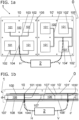
- Received microwave thermal emission signals are very weak and need to be amplified for further signal processing. Frequent internal calibration is required to correct gain and offset drifts in time by the optimized electronics 2 as depicted in Figure 2 schematically. Gain drifts are correlated with offset drifts, which are both functions of temperature, and can both influence the resulting brightness temperature measurement and retrieval. Therefore also the electronics 2 was optimized, resulting in an electronics 2 as follows.
- the radiometer electronics 2 comprises the following components in direction of signal transmission: Antenna inputs 20, n-port switch 21, calibration matched load 22, inverted LNA (low noise amplifier) and active cold load 23, with output terminated by a LNA termination 24, isolator 25, first bandpass filter 26 (especially for L-band, 1400-1427 MHz), first LNA 27, second bandpass filter 28, second LNA 29, third bandpass filter 30, square law power detector 31, lowpass filter 32, ADC (Analog to Digital Converter) 33 and computer unit 34. All components are in particular arranged in a housing. The inputs and outputs are indicated in the schematic drawing figure 2 .
- the calibration matched load 22 and/or inverted LNA and active cold load 23 with an LNA termination 24 are placed and connected to the n-port switch 21.
- the calibration matched load 22 is not in the main RF chain and acts only as an ambient brightness temperature source.
- the inverted LNA and active cold load 23 and the LNA termination 24 are not in the main RF chain and are optional.
- the LNA termination 24 is a passive electronic component, only to terminate the inverted LNA and cold load 23. This prevents reflections and non-linear behavior of the inverted LNA 23 that would change its apparent microwave brightness temperature.
- the signals of at least one antenna 1 are fed, most preferred from a two-part patch array antenna 1 as disclosed above. All components are adapted to the frequency range of interest, wherein some components are for temperature calibration tasks, as the calibration matched load 22 and the inverted LNA and cold load 23, terminated with the LNA termination 24.
- the inverted LNA and cold load 23 is not actually used as an amplifier and is not in the main RF chain. Both components 23, 24 are not in the main RF chain and only act as a calibration cold brightness temperature source. Temperature sensors, for example thermocouples are not depicted here. For a person skilled in the art, it is known how the wiring and/or microwave transmission between the components is done and which technical requirements to be met by the components for the frequency range of interest.
- the whole radiometer electronics can be manufactured on one PCB using microstrip or CPW to attach the components.
- the electronics 2 shows a simple direct-detect RF front-end with a square-law power detector 31 back-end.
- this established and simple method was used in this design for the sake of simplicity, low-power consumption, and stability.
- Digital backends have been shown to provide mitigation to Radio Frequency Interference (RFI), but with a high sampling rate of the power detector we can also filter RFI in the time domain.
- the RF front-end is constructed using commercial components.
- the RF front-end comprises: switch 21, in particular a four-port switch 21, isolator 25, inverted LNA 23, LNAs 27, 29 and L-band filters 26, 28, 30, and an integrating low-pass filter 32 as smoothing or integration RC filter on the DC output of the detector.
- bandpass filters 26, 28, 30 in particular ceramic cavity bandpass filters are used, for tuning to the passive-protected RF band/ theoretically free from radio-frequency interference.
- the square-law power detector 31 whose output voltage is proportional to the square of the amplitude-modulated input voltage, is then low-pass filtered by lowpass filter 32 and sampled by the A/D converter 33 at ⁇ 2 kHz.
- the lowpass filter 32 cutoff frequency or time constant is adjusted according to the A/D sample rate.
- the small computer unit 34 collects and saves the detector data and the optional temperature sensor data as well as controlling the switch.
- the radiometer electronics 2 is nominally calibrated at ⁇ 80 ms intervals using the two internal calibration loads 22, 23/24, an ambient temperature monitored matched load 22 and an active cold load 23/24.
- the physical temperature of the active cold load is also monitored, and its brightness temperature is characterized as a function of physical temperature using measurements of well characterized cold sky brightness temperature.
- the components are chosen to deliver 50- ⁇ input impedance.
- temperature sensors should be placed at the used antenna.
- a temperature sensor should be located on each patch array 10, 10'.
- the radiometer electronics 2 offers adjustable integration time and fast time domain sampling.
- adjustable integration time allows for better radiometric accuracy for high flight altitude missions when spatial resolution is inherently lower, and vice-versa by sacrificing some radiometric accuracy. Extremely high spatial resolution is possible at low flight altitudes.
- integration time can be long resulting in low noise effective delta temperature (NEDT), or enhanced radiometric resolution.
- NEDT noise effective delta temperature
- Radio-frequency interference RFID
- the invention utilizes the theory of Gaussianity of noise in the time-domain to filter samples containing interference.
- Receivers using heterodyne or super-heterodyne detection, such as SDRs are subject to uncertainty in the received frequency, and thus brightness temperature, from drifts in the temperature and power dependent local oscillator.
- the direct detection, with a front-end bandpass filter, used here provides a balance between simplicity and stability.
- the other designs discussed in the prior art above do not incorporate a front-end filter, which would allow RFI from a broad range of frequencies to saturate the first amplifier stage and compromise the measurements.
- the resulting radiometer 0 is a direct detection, total-power, internally calibrated radiometer operating at the frequency band 1400-1426 MHz and has the following advantages due to the special antenna 1 design and/or the electronics 2 over the state-of-the-art are:
- the total radiometer 0 provides advantages over the state-of-the-art because digital-backend detection with technologies such as software defined radios gather large amounts of data, require considerable processing time, and also consume more power than the design presented here. While digital detection allows filtering of RFI in the frequency domain, it is also subject to multiple additional noise sources including aliasing and frequency folding, local oscillator drift, phase error of in-phase and quadrature samples, etc.
Landscapes
- Physics & Mathematics (AREA)
- General Physics & Mathematics (AREA)
- Engineering & Computer Science (AREA)
- Astronomy & Astrophysics (AREA)
- Aviation & Aerospace Engineering (AREA)
- Remote Sensing (AREA)
- Electromagnetism (AREA)
- Radiation Pyrometers (AREA)
- Variable-Direction Aerials And Aerial Arrays (AREA)
- Waveguide Aerials (AREA)
- Details Of Aerials (AREA)
Claims (14)
- Patch-Array-Antenne (1) für ein tragbares stabiles Mikrowellenradiometer mit geringer Masse (0) zur Messung von Mikrowellen im Spektralbereich zwischen 1 und 300 GHz, anschließbar an eine Radiometerelektronik (2),
dadurch gekennzeichnet, dass
die Patch-Array-Antenne (1) mindestens ein Patch-Array (10, 10') mit einer Patch-Substratschicht (100, 100') in Form einer Leiterplatte aus einem dielektrischen Material umfasst, auf der ein Muster aus gedruckten Patches (101, 101') auf einer Vorderseite der Patch-Substratschicht (100, 100') gedruckt ist, wobei die gedruckten Patches (101, 101') über Inset-Feeds (102, 102') mit Streifenleitungen (103, 103') auf derselben Ebene verbunden sind, wie die gedruckten Patches (101, 101') auf der Leiterplatte, wobei Verbindungslinien (1030) mit den Streifenleitungen (103, 103') verbunden und durch die Patch-Substratschicht (100, 100') durch eine Erdleiterschicht (108, 108'), die an der Rückseite der Patchsubstratschicht (100, 100') in einem definierten Abstand (d, d') befestigt ist und nur zwischen beiden Schichten (100, 100', 108, 108') einen Luftspalt (106, 106') bildet, wobei der Luftspalt (106, 106') durch eine Vielzahl von einzelnen Einzelabstandshaltern (107, 107') und derart, dass die Verbindungsleitungen (1030, 1030') durch die Erdleiterschicht (108, 108') in mindestens einen an einer Rückseite der Erdleiterschicht (108, 108') befestigten HF-Koaxialstecker (104, 104') geführt werden, der direkt ohne Umweg über Kabel mit der Radiometerelektronik (2) verbunden werden kann. - Patch-Array-Antenne (1) nach Anspruch 1, wobei die Abstände (d, d') zwischen der Patch-Substratschicht (100, 100') und der Erdleiterschicht (108, 108') und damit dem mindestens einen Luftspalt (106, 106') zwischen 5 und 9 mm liegen.
- Patch-Array-Antenne (1) nach Anspruch 1 oder 2, wobei die einzelnen Abstandshalter (107, 107') aus elektrisch isolierenden Materialien, insbesondere Polymeren, bevorzugt aus Silikon oder Polytetrafluorethylen bestehen und durch Verbindungsmittel (105, 105') zwischen der Patch-Substratschicht (100, 100') und der Erdleiterschicht (108, 108') verbunden sind.
- Patch-Array-Antenne (1) nach Anspruch 3, wobei die Verbindungsmittel (105, 105') elektrisch isolierende Materialien, insbesondere Schrauben aus synthetischen Polymeren, wie Polyamiden, sind.
- Patch-Array-Antenne (1) nach einem der vorhergehenden Ansprüche, wobei die Erdleiterschicht (108, 108') eine Leiterplatte mit einer Erdungsmetallschicht oder einer Metallplatte ist.
- Patch-Array-Antenne (1) nach einem der vorhergehenden Ansprüche, wobei der mindestens eine HF-Koaxialstecker (104, 104') an der Rückseite der Erdleiterschicht (108, 108') angebracht und über die Kabel an der Radiometerelektronik (2) anschlussbar ist.
- Patch-Array-Antenne (1) nach einem der vorhergehenden Ansprüche, wobei die Patch-Array-Antenne (1) zwei identisch geformte Patch-Arrays (10, 10') mit einer Patch-Substratschicht (100, 100'), Luftspalten (106, 106'), die durch eine Vielzahl von Abstandshaltern (107, 107') gebildet sind, und einer Erdleiterschicht (108, 108') umfasst, wobei mindestens die Patch-Substratschichten (100, 100') der verschiedenen Patch-Arrays (10, 10') sind relativ zueinander so gedreht, dass die Muster der Patches (101, 101') auf den Patch-Substratschichten (100, 100') um 90° zueinander gedreht sind, um die gleichzeitige Messung unterschiedlich polarisierter Strahlung zu ermöglichen.
- Patch-Array-Antenne (1) nach einem der vorhergehenden Ansprüche, wobei ein Temperatursensor an dem Patch-Array (10, 10') angebracht und über ein Kabel an die Elektronik (2) anschließbar ist.
- Tragbares stabiles Mikrowellenradiometer (0) mit geringer Masse zum Messen von Mikrowellen im Spektralbereich zwischen 1 und 300 GHz, umfassend mit mindestens einer Patch-Array-Antenne (1) nach einem der vorhergehenden Ansprüche und einer angeschlossenen Radiometerelektronik (2) mit Hochfrequenzkomponenten und Signalverarbeitungskomponenten, wobei die Radiometerelektronik (2) die folgenden Komponenten in Richtung der Signalübertragung (S) umfasst:
mindestens einen Antenneneingang (20), einen N-Port-Schalter (21), einen Isolator (25), einen ersten Bandpassfilter (26), einen ersten rauscharmen Verstärker (27), einen zweiten Bandpassfilter (28), einen zweiten rauscharmen Verstärker (29), einen dritten Bandpassfilter (30), einen Leistungsdetektor (31), einen Tiefpassfilter (32), einen Analog-Digital-Wandler (33) und eine Computereinheit (34), wobei der mindestens eine Antenneneingang (20) mit der Patch-Array-Antenne (1) verbunden ist. - Tragbares stabiles Mikrowellenradiometer (0) mit geringer Masse nach Anspruch 9, wobei an den n-Port-Schalter (21) eine erste abgestimmte Last (22) und/oder ein invertierter LNA und eine aktive kalte Last (23) mit einem LNA-Abschluss (24) platziert und angeschlossen sind.
- Tragbares stabiles Mikrowellenradiometer mit geringer Masse (0) nach einem der Ansprüche 9 oder 10, wobei der Leistungsdetektor (31) ein quadratischer Leistungsdetektor (31) ist.
- Tragbares stabiles Mikrowellenradiometer mit geringer Masse (0) nach Anspruch 10, wobei die erste abgestimmte Last (22) und die aktive Kaltkalibrierquelle (23) mit Temperatursensoren zu Kalibrierzwecken ausgestattet sind.
- Tragbares stabiles Mikrowellenradiometer (0) mit geringer Masse nach einem der Ansprüche 9 bis 12, wobei an der Elektronik (2) zwei Antenneneingänge (20) für zwei Patch-Antennen (1) oder zwei Patch-Arrays (10, 10') vorgesehen sind und der n-Port-Schalter (21) ein Vier-Port-Switch (21) ist.
- Tragbares stabiles Mikrowellenradiometer mit geringer Masse (0) nach Anspruch 10, wobei ein Temperatursensor zu Kalibrierzwecken an jedem Patch-Array (10, 10') und/oder an der ersten abgestimmten Kalibrierlast (22) und/oder an der invertierten LNA und der aktiven Kältelast (23) angebracht ist.
Applications Claiming Priority (2)
| Application Number | Priority Date | Filing Date | Title |
|---|---|---|---|
| EP20176083.2A EP3913741A1 (de) | 2020-05-22 | 2020-05-22 | Tragbares mikrowellenradiometer mit niedriger masse und niedriger leistung mit radiometerantenne und radiometerelektronik |
| PCT/EP2021/061159 WO2021233656A1 (en) | 2020-05-22 | 2021-04-28 | Portable low-mass and low-power microwave radiometer with radiometer antenna and radiometer electronics |
Publications (3)
| Publication Number | Publication Date |
|---|---|
| EP4154351A1 EP4154351A1 (de) | 2023-03-29 |
| EP4154351B1 true EP4154351B1 (de) | 2025-07-09 |
| EP4154351C0 EP4154351C0 (de) | 2025-07-09 |
Family
ID=70804533
Family Applications (2)
| Application Number | Title | Priority Date | Filing Date |
|---|---|---|---|
| EP20176083.2A Withdrawn EP3913741A1 (de) | 2020-05-22 | 2020-05-22 | Tragbares mikrowellenradiometer mit niedriger masse und niedriger leistung mit radiometerantenne und radiometerelektronik |
| EP21721126.7A Active EP4154351B1 (de) | 2020-05-22 | 2021-04-28 | Tragbares mikrowellenradiometer mit niedriger masse und niedriger leistung mit radiometerantenne und radiometerelektronik |
Family Applications Before (1)
| Application Number | Title | Priority Date | Filing Date |
|---|---|---|---|
| EP20176083.2A Withdrawn EP3913741A1 (de) | 2020-05-22 | 2020-05-22 | Tragbares mikrowellenradiometer mit niedriger masse und niedriger leistung mit radiometerantenne und radiometerelektronik |
Country Status (4)
| Country | Link |
|---|---|
| US (1) | US20230208046A1 (de) |
| EP (2) | EP3913741A1 (de) |
| ES (1) | ES3036328T3 (de) |
| WO (1) | WO2021233656A1 (de) |
Families Citing this family (5)
| Publication number | Priority date | Publication date | Assignee | Title |
|---|---|---|---|---|
| CN114441863B (zh) * | 2022-01-19 | 2022-09-13 | 中国科学院国家空间科学中心 | 一种星载综合孔径微波辐射计在轨射频干扰处理方法 |
| CN116045862B (zh) * | 2022-11-08 | 2026-02-03 | 吉林大学 | 基于微波辐射亮温识别月壤分层的方法 |
| JP7558323B2 (ja) | 2023-03-07 | 2024-09-30 | 耀登科技股▲ふん▼有限公司 | アンテナ構造体 |
| EP4632169A1 (de) * | 2024-04-10 | 2025-10-15 | Sika Technology AG | Verfahren zur detektion von feuchtigkeit in einer dachstruktur |
| CN119247360B (zh) * | 2024-12-04 | 2025-02-25 | 中国海洋大学 | 一种用于星载一维综合孔径微波辐射计的分辨率增强方法 |
Family Cites Families (11)
| Publication number | Priority date | Publication date | Assignee | Title |
|---|---|---|---|---|
| US5444453A (en) * | 1993-02-02 | 1995-08-22 | Ball Corporation | Microstrip antenna structure having an air gap and method of constructing same |
| JP3471617B2 (ja) * | 1997-09-30 | 2003-12-02 | 三菱電機株式会社 | 平面アンテナ装置 |
| US6828556B2 (en) * | 2001-09-28 | 2004-12-07 | Hrl Laboratories, Llc | Millimeter wave imaging array |
| EP2081251B1 (de) * | 2008-01-15 | 2018-07-11 | HMD Global Oy | Patchantenne |
| US8463179B2 (en) * | 2010-12-22 | 2013-06-11 | Qualcomm Incorporated | Electromagnetic patch antenna repeater with high isolation |
| US9692126B2 (en) * | 2014-05-30 | 2017-06-27 | King Fahd University Of Petroleum And Minerals | Millimeter (mm) wave switched beam antenna system |
| CA2916617A1 (en) | 2016-01-04 | 2017-07-04 | WOLLEBEN, Maik | Portable radiometer/radar system for remote sensing of soil moisture |
| CN106384882B (zh) * | 2016-11-01 | 2019-05-21 | 锐捷网络股份有限公司 | 贴片天线和贴片天线制造方法 |
| US20190125420A1 (en) * | 2017-10-31 | 2019-05-02 | Bone Solutions, Inc. | Bioabsorbable Composite Screw |
| US10804616B2 (en) * | 2018-03-27 | 2020-10-13 | Viasat, Inc. | Circuit architecture for distributed multiplexed control and element signals for phased array antenna |
| US11664585B2 (en) * | 2018-07-23 | 2023-05-30 | Ohio State Innovation Foundation | Bio-matched antenna |
-
2020
- 2020-05-22 EP EP20176083.2A patent/EP3913741A1/de not_active Withdrawn
-
2021
- 2021-04-28 US US17/926,660 patent/US20230208046A1/en active Pending
- 2021-04-28 ES ES21721126T patent/ES3036328T3/es active Active
- 2021-04-28 EP EP21721126.7A patent/EP4154351B1/de active Active
- 2021-04-28 WO PCT/EP2021/061159 patent/WO2021233656A1/en not_active Ceased
Also Published As
| Publication number | Publication date |
|---|---|
| EP4154351A1 (de) | 2023-03-29 |
| WO2021233656A1 (en) | 2021-11-25 |
| US20230208046A1 (en) | 2023-06-29 |
| ES3036328T3 (en) | 2025-09-17 |
| EP4154351C0 (de) | 2025-07-09 |
| EP3913741A1 (de) | 2021-11-24 |
Similar Documents
| Publication | Publication Date | Title |
|---|---|---|
| EP4154351B1 (de) | Tragbares mikrowellenradiometer mit niedriger masse und niedriger leistung mit radiometerantenne und radiometerelektronik | |
| Hobbs et al. | An ultra-wide bandwidth (704 to 4 032 MHz) receiver for the Parkes radio telescope | |
| Gasiewski et al. | Calibration and applications of polarization-correlating radiometers | |
| King et al. | The C-Band All-Sky Survey (C-BASS): design and implementation of the northern receiver | |
| US9383254B1 (en) | Symmetric absorber-coupled far-infrared microwave kinetic inductance detector | |
| Lahtinen et al. | A calibration method for fully polarimetric microwave radiometers | |
| Jam et al. | A submillimeter-wave near-field measurement setup for on-wafer pattern and gain characterization of antennas and arrays | |
| Suzuki et al. | Multi-chroic dual-polarization bolometric detectors for studies of the cosmic microwave background | |
| Hammar et al. | Low noise 874 GHz receivers for the international submillimetre airborne radiometer (ISMAR) | |
| CN104122273B (zh) | 基于多通道频带合成的辐射计 | |
| Uzawa et al. | Superconducting receiver technologies supporting ALMA and future prospects | |
| De Ory et al. | Optimized cross-polarized LEKIDs for W-band using sawtooth inductors | |
| Ho et al. | Lightweight and compact radiometers for soil moisture measurement: A review | |
| Hossain et al. | Multi-band orthogonal linear polarization discrimination planar array antenna | |
| Farhad et al. | SDR based agile radiometer with onboard RFI processing on a small UAS | |
| Bosch-Lluis et al. | Instrument design and performance of the high-frequency airborne microwave and millimeter-wave radiometer | |
| Hossain et al. | A novel dual‐band slot‐ring array antenna using both‐sided MIC technology for polarization detection | |
| Khatib et al. | Planar Metamaterial Absorbers for Calibration of Microwave Radiometers for Atmospheric Remote Sensing | |
| Bailey et al. | Multi-frequency synthetic thinned array antenna for the hurricane imaging radiometer | |
| Wang et al. | A digital correlation full-polarimetric microwave radiometer design and calibration | |
| McDaniel | Design, integration, and miniaturization of a multichannel ultra-wideband snow radar receiver and passive microwave components | |
| Polívka | Microwave radiometry and applications | |
| Voll et al. | A G-band cryogenic MMIC heterodyne receiver module for astronomical applications | |
| Goldie et al. | First characterization of a superconducting filter-bank spectrometer for hyper-spectral microwave atmospheric sounding with transition edge sensor readout | |
| Dickie et al. | 229 GHz FSS for the MetOp second generation Microwave Sounder instrument |
Legal Events
| Date | Code | Title | Description |
|---|---|---|---|
| STAA | Information on the status of an ep patent application or granted ep patent |
Free format text: STATUS: UNKNOWN |
|
| STAA | Information on the status of an ep patent application or granted ep patent |
Free format text: STATUS: THE INTERNATIONAL PUBLICATION HAS BEEN MADE |
|
| PUAI | Public reference made under article 153(3) epc to a published international application that has entered the european phase |
Free format text: ORIGINAL CODE: 0009012 |
|
| STAA | Information on the status of an ep patent application or granted ep patent |
Free format text: STATUS: REQUEST FOR EXAMINATION WAS MADE |
|
| 17P | Request for examination filed |
Effective date: 20221215 |
|
| AK | Designated contracting states |
Kind code of ref document: A1 Designated state(s): AL AT BE BG CH CY CZ DE DK EE ES FI FR GB GR HR HU IE IS IT LI LT LU LV MC MK MT NL NO PL PT RO RS SE SI SK SM TR |
|
| DAV | Request for validation of the european patent (deleted) | ||
| DAX | Request for extension of the european patent (deleted) | ||
| GRAP | Despatch of communication of intention to grant a patent |
Free format text: ORIGINAL CODE: EPIDOSNIGR1 |
|
| STAA | Information on the status of an ep patent application or granted ep patent |
Free format text: STATUS: GRANT OF PATENT IS INTENDED |
|
| INTG | Intention to grant announced |
Effective date: 20250227 |
|
| GRAS | Grant fee paid |
Free format text: ORIGINAL CODE: EPIDOSNIGR3 |
|
| GRAA | (expected) grant |
Free format text: ORIGINAL CODE: 0009210 |
|
| STAA | Information on the status of an ep patent application or granted ep patent |
Free format text: STATUS: THE PATENT HAS BEEN GRANTED |
|
| AK | Designated contracting states |
Kind code of ref document: B1 Designated state(s): AL AT BE BG CH CY CZ DE DK EE ES FI FR GB GR HR HU IE IS IT LI LT LU LV MC MK MT NL NO PL PT RO RS SE SI SK SM TR |
|
| REG | Reference to a national code |
Ref country code: GB Ref legal event code: FG4D |
|
| REG | Reference to a national code |
Ref country code: CH Ref legal event code: EP |
|
| REG | Reference to a national code |
Ref country code: IE Ref legal event code: FG4D |
|
| U01 | Request for unitary effect filed |
Effective date: 20250711 |
|
| U07 | Unitary effect registered |
Designated state(s): AT BE BG DE DK EE FI FR IT LT LU LV MT NL PT RO SE SI Effective date: 20250718 |
|
| REG | Reference to a national code |
Ref country code: ES Ref legal event code: FG2A Ref document number: 3036328 Country of ref document: ES Kind code of ref document: T3 Effective date: 20250917 |
|
| PG25 | Lapsed in a contracting state [announced via postgrant information from national office to epo] |
Ref country code: IS Free format text: LAPSE BECAUSE OF FAILURE TO SUBMIT A TRANSLATION OF THE DESCRIPTION OR TO PAY THE FEE WITHIN THE PRESCRIBED TIME-LIMIT Effective date: 20251109 |
|
| PG25 | Lapsed in a contracting state [announced via postgrant information from national office to epo] |
Ref country code: NO Free format text: LAPSE BECAUSE OF FAILURE TO SUBMIT A TRANSLATION OF THE DESCRIPTION OR TO PAY THE FEE WITHIN THE PRESCRIBED TIME-LIMIT Effective date: 20251009 |
|
| PG25 | Lapsed in a contracting state [announced via postgrant information from national office to epo] |
Ref country code: HR Free format text: LAPSE BECAUSE OF FAILURE TO SUBMIT A TRANSLATION OF THE DESCRIPTION OR TO PAY THE FEE WITHIN THE PRESCRIBED TIME-LIMIT Effective date: 20250709 |
|
| PG25 | Lapsed in a contracting state [announced via postgrant information from national office to epo] |
Ref country code: GR Free format text: LAPSE BECAUSE OF FAILURE TO SUBMIT A TRANSLATION OF THE DESCRIPTION OR TO PAY THE FEE WITHIN THE PRESCRIBED TIME-LIMIT Effective date: 20251010 |
|
| PG25 | Lapsed in a contracting state [announced via postgrant information from national office to epo] |
Ref country code: PL Free format text: LAPSE BECAUSE OF FAILURE TO SUBMIT A TRANSLATION OF THE DESCRIPTION OR TO PAY THE FEE WITHIN THE PRESCRIBED TIME-LIMIT Effective date: 20250709 |
|
| PG25 | Lapsed in a contracting state [announced via postgrant information from national office to epo] |
Ref country code: RS Free format text: LAPSE BECAUSE OF FAILURE TO SUBMIT A TRANSLATION OF THE DESCRIPTION OR TO PAY THE FEE WITHIN THE PRESCRIBED TIME-LIMIT Effective date: 20251009 |
|
| PG25 | Lapsed in a contracting state [announced via postgrant information from national office to epo] |
Ref country code: SM Free format text: LAPSE BECAUSE OF FAILURE TO SUBMIT A TRANSLATION OF THE DESCRIPTION OR TO PAY THE FEE WITHIN THE PRESCRIBED TIME-LIMIT Effective date: 20250709 |
|
| PGFP | Annual fee paid to national office [announced via postgrant information from national office to epo] |
Ref country code: GB Payment date: 20260327 Year of fee payment: 6 |