EP4153929B1 - Gassystem einer feuerwaffe - Google Patents
Gassystem einer feuerwaffe Download PDFInfo
- Publication number
- EP4153929B1 EP4153929B1 EP21728851.3A EP21728851A EP4153929B1 EP 4153929 B1 EP4153929 B1 EP 4153929B1 EP 21728851 A EP21728851 A EP 21728851A EP 4153929 B1 EP4153929 B1 EP 4153929B1
- Authority
- EP
- European Patent Office
- Prior art keywords
- gas
- piston
- force transmitter
- barrel
- firearm
- Prior art date
- Legal status (The legal status is an assumption and is not a legal conclusion. Google has not performed a legal analysis and makes no representation as to the accuracy of the status listed.)
- Active
Links
Images






Classifications
-
- F—MECHANICAL ENGINEERING; LIGHTING; HEATING; WEAPONS; BLASTING
- F41—WEAPONS
- F41A—FUNCTIONAL FEATURES OR DETAILS COMMON TO BOTH SMALLARMS AND ORDNANCE, e.g. CANNONS; MOUNTINGS FOR SMALLARMS OR ORDNANCE
- F41A5/00—Mechanisms or systems operated by propellant charge energy for automatically opening the lock
- F41A5/18—Mechanisms or systems operated by propellant charge energy for automatically opening the lock gas-operated
-
- F—MECHANICAL ENGINEERING; LIGHTING; HEATING; WEAPONS; BLASTING
- F41—WEAPONS
- F41A—FUNCTIONAL FEATURES OR DETAILS COMMON TO BOTH SMALLARMS AND ORDNANCE, e.g. CANNONS; MOUNTINGS FOR SMALLARMS OR ORDNANCE
- F41A5/00—Mechanisms or systems operated by propellant charge energy for automatically opening the lock
- F41A5/18—Mechanisms or systems operated by propellant charge energy for automatically opening the lock gas-operated
- F41A5/20—Mechanisms or systems operated by propellant charge energy for automatically opening the lock gas-operated using a gas piston arranged concentrically around the barrel
-
- F—MECHANICAL ENGINEERING; LIGHTING; HEATING; WEAPONS; BLASTING
- F41—WEAPONS
- F41A—FUNCTIONAL FEATURES OR DETAILS COMMON TO BOTH SMALLARMS AND ORDNANCE, e.g. CANNONS; MOUNTINGS FOR SMALLARMS OR ORDNANCE
- F41A5/00—Mechanisms or systems operated by propellant charge energy for automatically opening the lock
- F41A5/18—Mechanisms or systems operated by propellant charge energy for automatically opening the lock gas-operated
- F41A5/26—Arrangements or systems for bleeding the gas from the barrel
-
- F—MECHANICAL ENGINEERING; LIGHTING; HEATING; WEAPONS; BLASTING
- F41—WEAPONS
- F41A—FUNCTIONAL FEATURES OR DETAILS COMMON TO BOTH SMALLARMS AND ORDNANCE, e.g. CANNONS; MOUNTINGS FOR SMALLARMS OR ORDNANCE
- F41A5/00—Mechanisms or systems operated by propellant charge energy for automatically opening the lock
- F41A5/18—Mechanisms or systems operated by propellant charge energy for automatically opening the lock gas-operated
- F41A5/26—Arrangements or systems for bleeding the gas from the barrel
- F41A5/28—Adjustable systems
-
- F—MECHANICAL ENGINEERING; LIGHTING; HEATING; WEAPONS; BLASTING
- F41—WEAPONS
- F41A—FUNCTIONAL FEATURES OR DETAILS COMMON TO BOTH SMALLARMS AND ORDNANCE, e.g. CANNONS; MOUNTINGS FOR SMALLARMS OR ORDNANCE
- F41A21/00—Barrels; Gun tubes; Muzzle attachments; Barrel mounting means
- F41A21/30—Silencers
Definitions
- a gas system is used for the autoloading cycle for loading the cartridge and removing the shells.
- part of pressurized gas from the cartridge being fired is used to power the gas system to extract the spent case and chamber a new cartridge.
- Energy from the gas is transmitted through gas openings in the barrel of the firearm.
- This high-pressure gas impinges on a surface such as a piston head to provide motion for unlocking of the action, extraction of the spent case, ejection, cocking of the hammer and loading of a fresh cartridge.
- a short stroke gas piston operating system is common on modern rifles. It is defined as a gas piston which travels less than the distance of the bolt carrier.
- the present invention relates to gas systems operating based on the short stroke gas piston.
- an autoloader for a gas operated automated firearm comprising a gas chamber including an inner diameter and constructed and arranged to receive pressurized combustion gas from a gas port of a barrel of the firearm when a round is fired from the firearm; a piston having a piston head in fluid communication with said gas chamber, said piston constructed and arranged to move away from a firing position to actuate at least a portion of a cycle of the firearm when urged by pressurized combustion gas received in said gas chamber and an expansion valve disposed within the gas chamber, the expansion valve constructed and arranged to move along the inner diameter of the gas chamber from a firing position to increase a volume of said gas chamber when pressure in the gas chamber exceeds a threshold level.
- a regulator for a gas operated firearm auto loader comprising a chamber constructed and arranged to receive pressurized combustion gas from a gas port of a barrel of the firearm when a round is fired from the firearm, a piston having a piston head in fluid communication with said chamber, the piston constructed and arranged to move away from a firing position to actuate at least a portion of a cycle of the firearm when urged by pressurized combustion gas received in said chamber, and a throttling valve in fluid communication with said chamber, the throttling valve having a first position in which pressurized combustion gas from the gas port of a barrel of a firearm can flow into the chamber, and a second position in which pressurized combustion gas from the gas port of a barrel of a firearm cannot flow into the chamber, and wherein the throttling valve is configured to move from the first position to the second position when pressure in the chamber exceeds a threshold level.
- an automatic firearm having a barrel with a gas port therein and a reciprocating breech operating member, comprising a gas cylinder secured to the barrel in the vicinity of the barrel gas port, said gas cylinder defining a rearwardly opening, cylindrical chamber disposed parallel to the path of movement of said breech operating member, a cylindrical piston slidably and rotatably mounted within said cylinder chamber, said piston having a forwardly opening hollow portion, the rear end of said piston arranged to abut the breech operating member to impart rearward movement thereto, said cylinder having a gas passage therein communicating between the barrel gas port and the interior of said cylinder chamber, said piston having a reduced diameter annular groove on its periphery located in substantial alignment with said gas passage when said piston is in its forward position, said piston having at least ore generally radial hole in said reduced diameter annular groove, communicating with the said hollow portion of said piston
- a gas operating system for engaging the automatic or semi-automatic action of a small arms weapon, comprising: a gun barrel having a plurality of radial ports and having radial forward and rear stops fixed thereon; a displaceable cylinder with a gas ring block secured thereto, the cylinder having a short stroke between the radial forward and rear stops fixed on the gun barrel; a fixed piston attached coaxial to the gun barrel and having gas block sealing rings at rearward exterior surfaces of the piston; a gas chamber, formed by interior walls of the cylinder and piston and by outer surfaces of the gun barrel, wherein gas tightness of the gas chamber is established by the gas ring block of the cylinder and by the gas blocking sealing rings of the piston, and wherein the gas chamber receives in operation pressurized combustion gas from fired ammunition, the gas entering through the radial ports of the gun barrel; and a single locking nut comprising a threaded flash suppressor, configured to lock the piston over the gun barrel, wherein the rear stop is
- a gas-operated auto-loading shotgun comprising a valve body in the form having a hollow cylinder of small mass and having first and second pressure-receiving surfaces, a guide rod on which the valve body is slideably fitted, a partition wall having a relatively large valve opening with a large-diameter part and a small-diameter part and constituting a valve seat at its rim part around the valve opening, and a spring for continually biasing the valve body toward the valve seat, whereby the valve opening is normally closed by the rear end surfaces of the valve body and the guide rod.
- EP 0634620 A1 is disclosed a semi-automatic shotgun of the type comprising a magazine tube around which a cylinder is situated, the interior of which is in connection with the interior of the barrel and with, in this cylinder and around the magazine tube, on one hand, a piston, which can shift under the effect of a part of the propulsion gases and can cooperate with a sleeve, which is provided with a rod, which is capable to control the assembly of movable parts, and, on the other hand, a regulation or pressure control valve, springs provided for the control of the reverse motion of the sleeve and the regulation valve, which is completely situated in the piston unit.
- An object of the present invention is to create a gas system of a firearm by which the above described problems and disadvantages of gas systems known from prior art are eliminated or at least minimized.
- Another object of the present invention is to create an improved gas system of a firearm, in which human error caused disadvantages are minimized.
- Another object of the present invention is to provide an improved gas system of a firearm, which is not ammunition sensitive.
- the gas system is connected to the gas of the barrel only during the defined time and the gas system is automatically controlled to prevent unlimited amount of gas entering from the barrel to the gas block.
- the gas piston moves back, at the same time shutting the gas openings and finally making contact and transmitting energy/forces to the bolt carrier via the force transmitter assembly.
- the gas block is attached onto the barrel of the firearm.
- the gas block is attached around the barrel of the firearm.
- the gas block and the gas piston together form a hollow encapsulation which is filled with gas from barrel.
- the gas piston is connected via a spring-loaded pin or bushing to at least one force transmitter of the force transmitter assembly.
- the force transmitter assembly comprises a helical return spring, which is configured to function as a return-spring returning the force transmitter assembly and the gas piston to its initial position.
- FIG. 1 an example of a firearm 100 comprising a barrel 101 and gas system 10.
- the gas system 10 operates based on the short stroke gas piston system.
- the indexing groove 17 is to secure the gas piston 12 at correct position inside the gas block 11, which moves the gas piston 12 that actuates the force transmitter 15 included in the force transmitter assembly 13, which at the end pushes a bolt carrier.
- the force transmitter 15 is mounted to an opening 54 at one end of the gas piston 12.
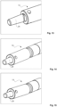
- FIG 8 is shown in more detail one end of the gas piston 12 in accordance with the example of figure 7 .
- the indexing groove 17 for securing the gas piston 12 has the beveled surface parts 20.
- figure 9 is shown in more detail front side of the gas piston 12 in accordance with the example of figure 7 .
- the gas piston 12 has a tubular form.
- FIG 10 is shown in more detail front side of an indexing counterpart 22 located below the gas piston 12 in accordance with the example of figure 2 .
- the gas system 10 comprises thus the indexing counterpart 22.
- the indexing counterpart 22 has an indexing protrusion 23, which corresponds to the indexing groove 17 of the indexing part 21 of the gas piston 12.
- a form-fitting joint is formed by the indexing groove 17 of the indexing part 21 and the indexing protrusion 23 of the indexing counterpart 22 and thus, the gas piston 12 is located at the correct position.
- the indexing protrusion 23 guides by the indexing groove 17 the gas piston 12 to its correct location.
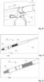
- the force transmitter assembly 13 in accordance with the example of figure 4 as an assembled view.
- the force transmitter assembly 13 comprises by the spring 47 ( fig. 4 ) spring-loaded bushing 14B at one end of the force transmitter 15 of the force transmitter assembly 13.
- the spring 47 effects the spring-load to the bushing 14B.
- the force transmitter assembly 13 comprises the helical, return spring 16, which functions as the return-spring returning the force transmitter assembly 13, when the bolt carrier has returned back.
- the helical, return spring 16 is located at a spring bushing 52.
- the force transmitter assembly 13 also comprises a bushing 53 for guiding the force transmitter 15.
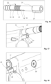
- FIG 13 is shown a more detailed example of an example of an end 25 of the force transmitter assembly 13 in accordance with the example of figure 4 .
- the end 25 of the force transmitter assembly 13 is tapered for controlling the position of the force transmitter assembly 13 in conjunction with a gas piston 12 ( fig. 16 ).
- FIG 16 is shown a more detailed example of an alternative of the indexing part 21 of the gas piston 12.
- the indexing part 21 of the gas piston 12 has a protrusion 27, which corresponds to the indexing groove 27 of the indexing counterpart 22 ( fig. 17 ).
- a form-fitting joint is formed by the indexing groove 26 and the indexing protrusion 27 and thus, the gas piston 12 is located at the correct position.
- the indexing protrusion 27 guides by the indexing groove 26 the gas piston 12 to its correct location.
- figure 17 is shown the example of figure 16 yet in greater detail. Additionally, in the figure is shown the gas piston 12 at the position, where it has travelled to contact the force transmitter 15. In this position no more gas passes from the barrel 101 of the firearm 100 to the gas piston 12 and charging is finished. Only the gas encapsulated inside the gas block/gas piston 12 volume is contributing to the cycling of the weapon now.
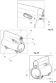
- FIGS 18 and 19 is shown the example of figure 10 .
- the press button assembly 28 is pressed down and the indexing counterpart 22 is unlocked and the gas piston 12 is released as shown in figs. 7-9 .
- the positioning tag 57 positions the barrel 101 and the gas block 11.
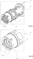
- FIGS 20-21 is shown the gas block 11 of the gas system 10. Inside the gas block 11 a space 29 is provided for the gas piston 12. Towards the space 29 inside the gas block 11 grooving 30 is provided for crust removal and gas sealing. At least one bore 31 is provided also in the gas block 11 for the indexing counterpart 22. Additionally, one exhaust opening 32 is provided on the front of the gas block 11.
- the gas block 11 will be attached onto the barrel 101 of the firearm 100 by attachment means, for example by spiral locking pins 33.
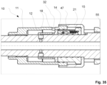
- stage 1 when a shot is fired and the bullet B has not yet reached the gas openings 18 and no gas passes yet into the gas block 11.
- openings of the gas piston 12 are aligned with the gas openings 18 and the exhaust opening 32 is closed by the gas piston 12.
- the gas system 10 is still in its initial setting.
- gas will start streaming into the gas block 11.
- the pressure inside the gas block 11 rises and the gas piston 12 starts moving, while the bullet B continues its travelling towards the end of the barrel 101.
- the gas piston 12 acts on the bushing 14B or the spring loaded pin 14 respectively ( figs.4-6 ) integrated into the force transmitter assembly 13 ( figs. 2-7 , 11-15 ) and the force transmitter 15 ( figs. 2-7 , 11-12 , 17 ), which do not move at this point and hence do not transmit momentum onto the bolt carrier.
- the cycling operation has not yet begun.
- stage 2 when the bullet B has reached the end of the barrel 101.
- the gas piston 12 has moved to rest against the force transmitter assembly 13 ( figs. 2-7 , 11-15 ) and the force transmitter 15 ( figs. 2-7 , 11-12 , 17 ), which are still stationary and have not yet accelerated the bolt carrier.
- no more gas from barrel 101 can flow into the gas openings 18 and the exhaust opening 32 is still closed.
- pressure inside the gas block 11 acts onto the bolt carrier by means of the force transmitter assembly 13 ( figs. 2-7 , 11-15 ) and the force transmitter 15 ( figs. 2-7 , 11-12 , 17 ).
- FIG 24 are shown stages 3 and 4, when the bullet B is long gone and travels towards its target along its trajectory.
- the pressurized gas enclosed within the internal volume of the gas openings 18 has carried out work and by means of the gas piston 12 pushed the force transmitter assembly 13 ( figs. 2-7 , 11-15 ) and the force transmitter 15 ( figs. 2-7 , 11-12 , 17 ) backwards for a certain distance and therewith transmitted momentum to the bolt carrier.
- the force transmitter assembly 13 ( figs. 2-7 , 11-15 ), the force transmitter 15 ( figs. 2-7 , 11-12 , 17 ) and the gas piston 12 stop at some point and the bolt carrier and the bolt continues moving on its own in accordance to "the short-stroke system"- principle.
- FIG. 25 is shown another example of a gas system 10 of the firearm 100.
- the gas system 10 is located around the barrel 101 of the firearm 100.
- the gas block 11 and the indexing part 21 are not moving parts but instead stay at their locations.
- the force transmitter assembly 13 has pushed the gas piston 12 to its front position and thus, the spring-loaded pins 14 have pushed the gas piston 12 to its front position and the gas can flow through the gas openings 18 to the space in between the gas piston 12 and the gas block 11.
- Pressure of the gas in the space between the gas piston 12 and the gas block 11 moves the gas piston 12 and from the gas opening 18 no further gas can enter the space between the gas piston 12 and the gas block 11.
- the spring-loaded pins 14 of the force transmitter sleeve 15 have been pressed in to pressed position.
Landscapes
- Engineering & Computer Science (AREA)
- General Engineering & Computer Science (AREA)
- Fluid-Damping Devices (AREA)
Claims (7)
- Schusswaffe (100), umfassend einen Lauf (101), umfassend eine Gasöffnung, und ein Gassystem (10), dessen Gassystem (10) einen Gasblock (11), einen Gaskolben (12), eine Kraftübertragungsanordnung (13), umfassend mindestens einen Kraftübertrager (15), Gasöffnungen (18), die sich an dem Gaskolben (12) befinden, umfasst, dessen Gasblock (11) fest an dem Lauf (101) befestigt ist, in dessen Gassystem (10) das Gas ausgestaltet ist, um durch die Gasöffnung des Laufs (101) über die Gasöffnungen (18) des Gassystems in den Gasblock (11) zu strömen und den Gaskolben (12) in Bewegung zu setzen, in dessen Gassystem (10) der Gaskolben (12) während der Bewegung nach hinten ausgestaltet ist, um die Gasöffnung des Laufs (101) für eine definierte Zeitspanne zu schließen und dass der Gaskolben (12) die Leistung/Energie des Verbrennungsgases an die Kraftübertragungsanordnung (13) nicht überträgt, solange die Gasöffnungen (18) des Gassystems (10) nicht geschlossen sind, dessen Gassystem (10) eine Auslassöffnung (32) in dem Gasblock (11) umfasst und die mit dem Umgebungsdruck verbundene Auslassöffnung (32) nach einer bestimmten Zeitspanne geöffnet wird, dadurch gekennzeichnet, dass das Gassystem (10) ein Indexteil (21), umfassend abgeschrägte Oberflächen (20), und eine Indexnut (17) und ein Indexgegenstück (22) mit einem Indexvorsprung (23), der der Indexnut (17) des Indexteils (21) des Gaskolbens (12) entspricht, umfasst, um die Gasöffnungen (18) des Gaskolbens (12) mit Gasöffnungen in dem Lauf (101) und dem Gasblock (11) ausgerichtet zu halten, und wobei der Gaskolben (12) durch das Indexteil (21) positioniert wird, und dass der Gaskolben (12) über einen federbelasteten Stift oder eine federbelastete Buchse (14; 14B) mit mindestens einem Kraftübertrager (15) der Kraftübertragungsanordnung (13) verbunden ist.
- Schusswaffe nach Anspruch 1, dadurch gekennzeichnet, dass das Gassystem (10) ein Kurzhub-Gaskolbensystem ist.
- Schusswaffe nach Anspruch 1 oder 2, dadurch gekennzeichnet, dass der Gasblock (11) auf dem Lauf (101) der Schusswaffe (100) befestigt ist.
- Schusswaffe nach Anspruch 1 oder 2, dadurch gekennzeichnet, dass der Gasblock (11) um den Lauf (101) der Schusswaffe (100) befestigt ist.
- Schusswaffe nach irgendeinem der vorhergehenden Ansprüche, dadurch gekennzeichnet, dass der Gasblock (11) und der Gaskolben (12) zusammen eine hohle Umhüllung bilden, die mit Gas aus dem Lauf (101) gefüllt ist.
- Schusswaffe nach irgendeinem der vorhergehenden Ansprüche, dadurch gekennzeichnet, dass die Kraftübertragungsanordnung (13) eine schraubenförmige Rückstellfeder (16) umfasst, die ausgestaltet ist, um als Rückstellfeder zu fungieren, die die Kraftübertragungsanordnung (13) zurückstellt.
- Schusswaffe nach irgendeinem der vorhergehenden Ansprüche, dadurch gekennzeichnet, dass die Außenoberfläche des Gaskolbens (12) mit Nuten (61) zur Entfernung von Verkrustungen versehen ist.
Priority Applications (2)
| Application Number | Priority Date | Filing Date | Title |
|---|---|---|---|
| RS20250557A RS66867B1 (sr) | 2020-05-20 | 2021-05-20 | Gasni sistem vatrenog oružja |
| HRP20250683TT HRP20250683T1 (hr) | 2020-05-20 | 2021-05-20 | Plinski sustav vatrenog oružja |
Applications Claiming Priority (2)
| Application Number | Priority Date | Filing Date | Title |
|---|---|---|---|
| FI20205509A FI129617B (en) | 2020-05-20 | 2020-05-20 | Gas system for a firearm |
| PCT/EP2021/063474 WO2021234090A1 (en) | 2020-05-20 | 2021-05-20 | Gas system of a firearm |
Publications (3)
| Publication Number | Publication Date |
|---|---|
| EP4153929A1 EP4153929A1 (de) | 2023-03-29 |
| EP4153929C0 EP4153929C0 (de) | 2025-03-12 |
| EP4153929B1 true EP4153929B1 (de) | 2025-03-12 |
Family
ID=76197423
Family Applications (1)
| Application Number | Title | Priority Date | Filing Date |
|---|---|---|---|
| EP21728851.3A Active EP4153929B1 (de) | 2020-05-20 | 2021-05-20 | Gassystem einer feuerwaffe |
Country Status (11)
| Country | Link |
|---|---|
| US (1) | US12163754B2 (de) |
| EP (1) | EP4153929B1 (de) |
| AU (1) | AU2021275485B2 (de) |
| CA (1) | CA3181941A1 (de) |
| ES (1) | ES3018478T3 (de) |
| FI (1) | FI129617B (de) |
| HR (1) | HRP20250683T1 (de) |
| HU (1) | HUE071430T2 (de) |
| PL (1) | PL4153929T3 (de) |
| RS (1) | RS66867B1 (de) |
| WO (1) | WO2021234090A1 (de) |
Families Citing this family (1)
| Publication number | Priority date | Publication date | Assignee | Title |
|---|---|---|---|---|
| HRP20221357T1 (hr) * | 2019-10-04 | 2022-12-23 | Glock Technology Gmbh | Karabin na plinski pogon |
Family Cites Families (26)
| Publication number | Priority date | Publication date | Assignee | Title |
|---|---|---|---|---|
| US2409225A (en) * | 1944-09-05 | 1946-10-15 | Wilbur A Schaich | Gas system for firearms |
| US2482880A (en) * | 1947-01-17 | 1949-09-27 | Olin Ind Inc | Gas-operated self-loading firearm |
| US2714334A (en) * | 1949-02-11 | 1955-08-02 | Earle M Harvey | Breech bolt lock for automatic firearms |
| FR1286037A (fr) * | 1961-01-19 | 1962-03-02 | Perfectionnement aux fusils de chasse à répétition | |
| EP0054088B1 (de) * | 1980-12-11 | 1985-07-17 | Chartered Industries Of Singapore Private Limited | Gasdruckbetätigte automatische oder halbautomatische Feuerwaffen |
| JPH067039B2 (ja) * | 1985-02-14 | 1994-01-26 | 豊和工業株式会社 | 自動銃におけるガス圧作動機構のガス圧調整装置 |
| BE1007314A3 (fr) * | 1993-07-16 | 1995-05-16 | Browning Sa Societe Anonyme | Arme a feu perfectionnee. |
| IT250545Y1 (it) * | 2000-06-07 | 2003-09-24 | Beretta Armi Spa | Dispositivo a presa di gas migliorato per armi a caricamentoautomatico |
| US7779743B2 (en) * | 2006-01-30 | 2010-08-24 | Herring Geoffrey A | Gas piston assembly and bolt carrier for gas-operated firearms |
| US7461581B2 (en) * | 2006-07-24 | 2008-12-09 | Lwrcinternational, Llc | Self-cleaning gas operating system for a firearm |
| US8250964B2 (en) | 2007-08-29 | 2012-08-28 | Ra Brands, L.L.C. | Gas system for firearms |
| US8161864B1 (en) * | 2009-03-24 | 2012-04-24 | Sturm, Ruger & Company, Inc. | Firearm gas piston operating system |
| US8176837B1 (en) | 2009-10-11 | 2012-05-15 | Jason Stewart Jackson | Firearm operating rod |
| US9261314B1 (en) * | 2010-07-19 | 2016-02-16 | Jason Stewart Jackson | Sleeve piston for actuating a firearm bolt carrier |
| US8640598B1 (en) * | 2010-07-19 | 2014-02-04 | Jason Stewart Jackson | Sleeve piston for actuating a firearm bolt carrier |
| US8863639B2 (en) * | 2012-08-23 | 2014-10-21 | Lwrc International Llc | Adjustable gas block for a gas operated firearm |
| US8850951B2 (en) * | 2012-12-27 | 2014-10-07 | Holland Automatic Rifles Llc | Gas management system for a firearm |
| CA2953998C (en) * | 2014-07-02 | 2018-09-18 | Beretta Usa Corp. | Gas operating system for small arms with spring loaded gas valve |
| US9903675B2 (en) * | 2014-12-22 | 2018-02-27 | Charles B. Cassels | Multi-block gas regulator |
| US9702644B2 (en) | 2015-01-13 | 2017-07-11 | Sig Sauer, Inc. | Regulator for a firearm auto loader |
| US10724812B2 (en) * | 2018-01-16 | 2020-07-28 | Game Scout, LLC | Adjustable gas block |
| US11060807B2 (en) * | 2018-01-16 | 2021-07-13 | Game Scout, LLC | Adjustable gas block |
| US11125516B2 (en) * | 2018-01-22 | 2021-09-21 | American Tactical, Inc. | Upper receiver for modular shotgun |
| US10578381B2 (en) * | 2018-01-22 | 2020-03-03 | American Tactical, Inc. | Upper receiver for modular shotgun |
| RU2721644C1 (ru) * | 2019-03-11 | 2020-05-21 | Рустам Гашимович Мирзоев | Система автоматического оружия с отводом части пороховых газов из канала ствола через отверстие в нем |
| SI25816A (sl) * | 2019-03-29 | 2020-09-30 | Tomaž Razpet | Puška |
-
2020
- 2020-05-20 FI FI20205509A patent/FI129617B/en active IP Right Grant
-
2021
- 2021-05-20 PL PL21728851.3T patent/PL4153929T3/pl unknown
- 2021-05-20 HU HUE21728851A patent/HUE071430T2/hu unknown
- 2021-05-20 RS RS20250557A patent/RS66867B1/sr unknown
- 2021-05-20 CA CA3181941A patent/CA3181941A1/en active Pending
- 2021-05-20 HR HRP20250683TT patent/HRP20250683T1/hr unknown
- 2021-05-20 US US17/922,961 patent/US12163754B2/en active Active
- 2021-05-20 WO PCT/EP2021/063474 patent/WO2021234090A1/en not_active Ceased
- 2021-05-20 ES ES21728851T patent/ES3018478T3/es active Active
- 2021-05-20 EP EP21728851.3A patent/EP4153929B1/de active Active
- 2021-05-20 AU AU2021275485A patent/AU2021275485B2/en active Active
Also Published As
| Publication number | Publication date |
|---|---|
| AU2021275485A1 (en) | 2022-12-01 |
| RS66867B1 (sr) | 2025-06-30 |
| AU2021275485B2 (en) | 2026-05-07 |
| US12163754B2 (en) | 2024-12-10 |
| HUE071430T2 (hu) | 2025-09-28 |
| WO2021234090A1 (en) | 2021-11-25 |
| ES3018478T3 (es) | 2025-05-16 |
| EP4153929C0 (de) | 2025-03-12 |
| PL4153929T3 (pl) | 2025-07-14 |
| HRP20250683T1 (hr) | 2025-08-01 |
| FI20205509A1 (en) | 2021-11-21 |
| FI129617B (en) | 2022-05-31 |
| US20230160648A1 (en) | 2023-05-25 |
| EP4153929A1 (de) | 2023-03-29 |
| CA3181941A1 (en) | 2021-11-25 |
Similar Documents
| Publication | Publication Date | Title |
|---|---|---|
| US9328981B2 (en) | Self regulating gas system for suppressed weapons | |
| EP3164661B1 (de) | Gasbetriebssystem für handfeuerwaffen mit federbelastetem gasventil | |
| US9500423B2 (en) | Method and mechanism for automatic regulation of gas flow when mounting a suppressor to a firearm | |
| US3988964A (en) | Gas operated firearm with metering adjustment | |
| US9719739B2 (en) | Gas block balancing piston for auto-loading firearm | |
| US8893608B2 (en) | Gas piston system for M16/AR15 rifle or M4 carbine systems | |
| US10584928B2 (en) | Cased telescoped ammunition firearm with translating chamber | |
| US8074556B2 (en) | Locking systems for use with firearms | |
| US9097475B2 (en) | Gas-operated firearm with pressure compensating gas piston | |
| CN115398176A (zh) | 多发型气枪 | |
| US7987763B1 (en) | Double action firing pin system | |
| US20240288236A1 (en) | Firearm | |
| AU2021275485B2 (en) | Gas system of a firearm | |
| US11629921B2 (en) | Firearm | |
| KR102896483B1 (ko) | 가스 블록 | |
| GB1567317A (en) | Gas operated firearm | |
| US11187473B1 (en) | Firearm | |
| EP1363100B1 (de) | Druckgasgewehr |
Legal Events
| Date | Code | Title | Description |
|---|---|---|---|
| REG | Reference to a national code |
Ref country code: HR Ref legal event code: TUEP Ref document number: P20250683T Country of ref document: HR |
|
| STAA | Information on the status of an ep patent application or granted ep patent |
Free format text: STATUS: UNKNOWN |
|
| STAA | Information on the status of an ep patent application or granted ep patent |
Free format text: STATUS: THE INTERNATIONAL PUBLICATION HAS BEEN MADE |
|
| PUAI | Public reference made under article 153(3) epc to a published international application that has entered the european phase |
Free format text: ORIGINAL CODE: 0009012 |
|
| STAA | Information on the status of an ep patent application or granted ep patent |
Free format text: STATUS: REQUEST FOR EXAMINATION WAS MADE |
|
| 17P | Request for examination filed |
Effective date: 20221028 |
|
| AK | Designated contracting states |
Kind code of ref document: A1 Designated state(s): AL AT BE BG CH CY CZ DE DK EE ES FI FR GB GR HR HU IE IS IT LI LT LU LV MC MK MT NL NO PL PT RO RS SE SI SK SM TR |
|
| DAV | Request for validation of the european patent (deleted) | ||
| DAX | Request for extension of the european patent (deleted) | ||
| STAA | Information on the status of an ep patent application or granted ep patent |
Free format text: STATUS: EXAMINATION IS IN PROGRESS |
|
| 17Q | First examination report despatched |
Effective date: 20231120 |
|
| GRAP | Despatch of communication of intention to grant a patent |
Free format text: ORIGINAL CODE: EPIDOSNIGR1 |
|
| STAA | Information on the status of an ep patent application or granted ep patent |
Free format text: STATUS: GRANT OF PATENT IS INTENDED |
|
| INTG | Intention to grant announced |
Effective date: 20241127 |
|
| GRAS | Grant fee paid |
Free format text: ORIGINAL CODE: EPIDOSNIGR3 |
|
| GRAA | (expected) grant |
Free format text: ORIGINAL CODE: 0009210 |
|
| STAA | Information on the status of an ep patent application or granted ep patent |
Free format text: STATUS: THE PATENT HAS BEEN GRANTED |
|
| AK | Designated contracting states |
Kind code of ref document: B1 Designated state(s): AL AT BE BG CH CY CZ DE DK EE ES FI FR GB GR HR HU IE IS IT LI LT LU LV MC MK MT NL NO PL PT RO RS SE SI SK SM TR |
|
| REG | Reference to a national code |
Ref country code: GB Ref legal event code: FG4D |
|
| REG | Reference to a national code |
Ref country code: CH Ref legal event code: EP |
|
| REG | Reference to a national code |
Ref country code: DE Ref legal event code: R096 Ref document number: 602021027510 Country of ref document: DE |
|
| REG | Reference to a national code |
Ref country code: IE Ref legal event code: FG4D |
|
| U01 | Request for unitary effect filed |
Effective date: 20250327 |
|
| U07 | Unitary effect registered |
Designated state(s): AT BE BG DE DK EE FI FR IT LT LU LV MT NL PT RO SE SI Effective date: 20250402 |
|
| REG | Reference to a national code |
Ref country code: ES Ref legal event code: FG2A Ref document number: 3018478 Country of ref document: ES Kind code of ref document: T3 Effective date: 20250516 |
|
| PGFP | Annual fee paid to national office [announced via postgrant information from national office to epo] |
Ref country code: PL Payment date: 20250422 Year of fee payment: 5 |
|
| PGFP | Annual fee paid to national office [announced via postgrant information from national office to epo] |
Ref country code: GB Payment date: 20250618 Year of fee payment: 5 |
|
| PGFP | Annual fee paid to national office [announced via postgrant information from national office to epo] |
Ref country code: RS Payment date: 20250423 Year of fee payment: 5 Ref country code: NO Payment date: 20250519 Year of fee payment: 5 |
|
| PGFP | Annual fee paid to national office [announced via postgrant information from national office to epo] |
Ref country code: HR Payment date: 20250606 Year of fee payment: 5 |
|
| REG | Reference to a national code |
Ref country code: SK Ref legal event code: T3 Ref document number: E 46466 Country of ref document: SK |
|
| PGFP | Annual fee paid to national office [announced via postgrant information from national office to epo] |
Ref country code: HU Payment date: 20250527 Year of fee payment: 5 |
|
| REG | Reference to a national code |
Ref country code: HR Ref legal event code: ODRP Ref document number: P20250683T Country of ref document: HR Payment date: 20250606 Year of fee payment: 5 |
|
| PG25 | Lapsed in a contracting state [announced via postgrant information from national office to epo] |
Ref country code: GR Free format text: LAPSE BECAUSE OF FAILURE TO SUBMIT A TRANSLATION OF THE DESCRIPTION OR TO PAY THE FEE WITHIN THE PRESCRIBED TIME-LIMIT Effective date: 20250613 |
|
| U20 | Renewal fee for the european patent with unitary effect paid |
Year of fee payment: 5 Effective date: 20250617 |
|
| PGFP | Annual fee paid to national office [announced via postgrant information from national office to epo] |
Ref country code: TR Payment date: 20250523 Year of fee payment: 5 Ref country code: SK Payment date: 20250422 Year of fee payment: 5 |
|
| PGFP | Annual fee paid to national office [announced via postgrant information from national office to epo] |
Ref country code: CZ Payment date: 20250422 Year of fee payment: 5 |
|
| PGFP | Annual fee paid to national office [announced via postgrant information from national office to epo] |
Ref country code: IE Payment date: 20250522 Year of fee payment: 5 |
|
| REG | Reference to a national code |
Ref country code: HR Ref legal event code: T1PR Ref document number: P20250683 Country of ref document: HR |
|
| REG | Reference to a national code |
Ref country code: HU Ref legal event code: AG4A Ref document number: E071430 Country of ref document: HU |
|
| PG25 | Lapsed in a contracting state [announced via postgrant information from national office to epo] |
Ref country code: SM Free format text: LAPSE BECAUSE OF FAILURE TO SUBMIT A TRANSLATION OF THE DESCRIPTION OR TO PAY THE FEE WITHIN THE PRESCRIBED TIME-LIMIT Effective date: 20250312 |
|
| PGFP | Annual fee paid to national office [announced via postgrant information from national office to epo] |
Ref country code: ES Payment date: 20250826 Year of fee payment: 5 |
|
| PGFP | Annual fee paid to national office [announced via postgrant information from national office to epo] |
Ref country code: CH Payment date: 20250819 Year of fee payment: 5 |
|
| PG25 | Lapsed in a contracting state [announced via postgrant information from national office to epo] |
Ref country code: IS Free format text: LAPSE BECAUSE OF FAILURE TO SUBMIT A TRANSLATION OF THE DESCRIPTION OR TO PAY THE FEE WITHIN THE PRESCRIBED TIME-LIMIT Effective date: 20250712 |
|
| PLBE | No opposition filed within time limit |
Free format text: ORIGINAL CODE: 0009261 |
|
| STAA | Information on the status of an ep patent application or granted ep patent |
Free format text: STATUS: NO OPPOSITION FILED WITHIN TIME LIMIT |
|
| REG | Reference to a national code |
Ref country code: CH Ref legal event code: L10 Free format text: ST27 STATUS EVENT CODE: U-0-0-L10-L00 (AS PROVIDED BY THE NATIONAL OFFICE) Effective date: 20260121 |
|
| PG25 | Lapsed in a contracting state [announced via postgrant information from national office to epo] |
Ref country code: MC Free format text: LAPSE BECAUSE OF FAILURE TO SUBMIT A TRANSLATION OF THE DESCRIPTION OR TO PAY THE FEE WITHIN THE PRESCRIBED TIME-LIMIT Effective date: 20250312 |
|
| 26N | No opposition filed |
Effective date: 20251215 |