EP4153281B1 - Endoluminale freisetzungskanüle und anordnung - Google Patents
Endoluminale freisetzungskanüle und anordnung Download PDFInfo
- Publication number
- EP4153281B1 EP4153281B1 EP21726234.4A EP21726234A EP4153281B1 EP 4153281 B1 EP4153281 B1 EP 4153281B1 EP 21726234 A EP21726234 A EP 21726234A EP 4153281 B1 EP4153281 B1 EP 4153281B1
- Authority
- EP
- European Patent Office
- Prior art keywords
- cannula
- tip
- distal
- catheter
- endoluminal delivery
- Prior art date
- Legal status (The legal status is an assumption and is not a legal conclusion. Google has not performed a legal analysis and makes no representation as to the accuracy of the status listed.)
- Active
Links
Images


Classifications
-
- A—HUMAN NECESSITIES
- A61—MEDICAL OR VETERINARY SCIENCE; HYGIENE
- A61B—DIAGNOSIS; SURGERY; IDENTIFICATION
- A61B17/00—Surgical instruments, devices or methods
- A61B17/34—Trocars; Puncturing needles
- A61B17/3478—Endoscopic needles, e.g. for infusion
-
- A—HUMAN NECESSITIES
- A61—MEDICAL OR VETERINARY SCIENCE; HYGIENE
- A61M—DEVICES FOR INTRODUCING MEDIA INTO, OR ONTO, THE BODY; DEVICES FOR TRANSDUCING BODY MEDIA OR FOR TAKING MEDIA FROM THE BODY; DEVICES FOR PRODUCING OR ENDING SLEEP OR STUPOR
- A61M25/00—Catheters; Hollow probes
- A61M25/0067—Catheters; Hollow probes characterised by the distal end, e.g. tips
- A61M25/0068—Static characteristics of the catheter tip, e.g. shape, atraumatic tip, curved tip or tip structure
-
- A—HUMAN NECESSITIES
- A61—MEDICAL OR VETERINARY SCIENCE; HYGIENE
- A61M—DEVICES FOR INTRODUCING MEDIA INTO, OR ONTO, THE BODY; DEVICES FOR TRANSDUCING BODY MEDIA OR FOR TAKING MEDIA FROM THE BODY; DEVICES FOR PRODUCING OR ENDING SLEEP OR STUPOR
- A61M25/00—Catheters; Hollow probes
- A61M25/0067—Catheters; Hollow probes characterised by the distal end, e.g. tips
- A61M25/0082—Catheter tip comprising a tool
- A61M25/0084—Catheter tip comprising a tool being one or more injection needles
-
- A—HUMAN NECESSITIES
- A61—MEDICAL OR VETERINARY SCIENCE; HYGIENE
- A61M—DEVICES FOR INTRODUCING MEDIA INTO, OR ONTO, THE BODY; DEVICES FOR TRANSDUCING BODY MEDIA OR FOR TAKING MEDIA FROM THE BODY; DEVICES FOR PRODUCING OR ENDING SLEEP OR STUPOR
- A61M5/00—Devices for bringing media into the body in a subcutaneous, intra-vascular or intramuscular way; Accessories therefor, e.g. filling or cleaning devices, arm-rests
- A61M5/178—Syringes
- A61M5/31—Details
- A61M5/32—Needles; Details of needles pertaining to their connection with syringe or hub; Accessories for bringing the needle into, or holding the needle on, the body; Devices for protection of needles
- A61M5/3286—Needle tip design, e.g. for improved penetration
-
- A—HUMAN NECESSITIES
- A61—MEDICAL OR VETERINARY SCIENCE; HYGIENE
- A61M—DEVICES FOR INTRODUCING MEDIA INTO, OR ONTO, THE BODY; DEVICES FOR TRANSDUCING BODY MEDIA OR FOR TAKING MEDIA FROM THE BODY; DEVICES FOR PRODUCING OR ENDING SLEEP OR STUPOR
- A61M5/00—Devices for bringing media into the body in a subcutaneous, intra-vascular or intramuscular way; Accessories therefor, e.g. filling or cleaning devices, arm-rests
- A61M5/178—Syringes
- A61M5/31—Details
- A61M5/32—Needles; Details of needles pertaining to their connection with syringe or hub; Accessories for bringing the needle into, or holding the needle on, the body; Devices for protection of needles
- A61M5/329—Needles; Details of needles pertaining to their connection with syringe or hub; Accessories for bringing the needle into, or holding the needle on, the body; Devices for protection of needles characterised by features of the needle shaft
- A61M5/3291—Shafts with additional lateral openings
-
- A—HUMAN NECESSITIES
- A61—MEDICAL OR VETERINARY SCIENCE; HYGIENE
- A61B—DIAGNOSIS; SURGERY; IDENTIFICATION
- A61B17/00—Surgical instruments, devices or methods
- A61B17/00234—Surgical instruments, devices or methods for minimally invasive surgery
-
- A—HUMAN NECESSITIES
- A61—MEDICAL OR VETERINARY SCIENCE; HYGIENE
- A61B—DIAGNOSIS; SURGERY; IDENTIFICATION
- A61B17/00—Surgical instruments, devices or methods
- A61B17/00234—Surgical instruments, devices or methods for minimally invasive surgery
- A61B2017/00238—Type of minimally invasive operation
- A61B2017/00243—Type of minimally invasive operation cardiac
- A61B2017/00247—Making holes in the wall of the heart, e.g. laser Myocardial revascularization
-
- A—HUMAN NECESSITIES
- A61—MEDICAL OR VETERINARY SCIENCE; HYGIENE
- A61B—DIAGNOSIS; SURGERY; IDENTIFICATION
- A61B90/00—Instruments, implements or accessories specially adapted for surgery or diagnosis and not covered by any of the groups A61B1/00 - A61B50/00, e.g. for luxation treatment or for protecting wound edges
- A61B90/03—Automatic limiting or abutting means, e.g. for safety
- A61B2090/033—Abutting means, stops, e.g. abutting on tissue or skin
- A61B2090/036—Abutting means, stops, e.g. abutting on tissue or skin abutting on tissue or skin
-
- A—HUMAN NECESSITIES
- A61—MEDICAL OR VETERINARY SCIENCE; HYGIENE
- A61M—DEVICES FOR INTRODUCING MEDIA INTO, OR ONTO, THE BODY; DEVICES FOR TRANSDUCING BODY MEDIA OR FOR TAKING MEDIA FROM THE BODY; DEVICES FOR PRODUCING OR ENDING SLEEP OR STUPOR
- A61M25/00—Catheters; Hollow probes
- A61M25/0021—Catheters; Hollow probes characterised by the form of the tubing
- A61M2025/0042—Microcatheters, cannula or the like having outside diameters around 1 mm or less
-
- A—HUMAN NECESSITIES
- A61—MEDICAL OR VETERINARY SCIENCE; HYGIENE
- A61M—DEVICES FOR INTRODUCING MEDIA INTO, OR ONTO, THE BODY; DEVICES FOR TRANSDUCING BODY MEDIA OR FOR TAKING MEDIA FROM THE BODY; DEVICES FOR PRODUCING OR ENDING SLEEP OR STUPOR
- A61M25/00—Catheters; Hollow probes
- A61M25/0067—Catheters; Hollow probes characterised by the distal end, e.g. tips
- A61M25/0082—Catheter tip comprising a tool
- A61M25/0084—Catheter tip comprising a tool being one or more injection needles
- A61M2025/0089—Single injection needle protruding axially, i.e. along the longitudinal axis of the catheter, from the distal tip
Definitions
- the field of the present invention relates to an endoluminal delivery device, and in particular to a endoluminal delivery device for delivery of a substance to an extravascular or intramyocardial target site, according to the preamble of the independent claim.
- Minimally invasive techniques often use the vascular system to access specific sites or regions of the body, by inserting a catheter and/or guide wire assembly percutaneously through e.g. the femoral or radial artery, and subsequently steering through the vasculature to a specific site under the guidance of angiographic imaging.
- a catheter and/or guide wire assembly percutaneously through e.g. the femoral or radial artery, and subsequently steering through the vasculature to a specific site under the guidance of angiographic imaging.
- some sites within a body are not accessible, or difficult to access, using known techniques, due to the complexity and sizing of the vasculature.
- Various techniques and devices are known for administration via the vascular system of substances to specific and localized target sites within the body. Examples of procedures where such techniques are used are in chemotherapy, treatment of various immunological conditions and stem cell treatments.
- US 8,152,758 discloses a catheter assembly including a delivery cannula with multiple channels and an expandable distal portion, wherein two needles are threaded through channels and used for infusion of a substance into the vessel wall.
- US 5,464,395 shows an injection balloon catheter with side ports for needle injection into surrounding tissue.
- US 2008/0319314 discloses an injection catheter with internal channels and a tip electrode, with a needle threaded through the assembly such that it can protrude out through the distal tip.
- Other catheter systems with injection needles are shown in e.g. US 6,613,017B1 and US 6,796,963B1
- EP201 0263 A2 discloses a delivery catheter device system that is useable to deliver a substance, article or device to a location within the body of human or animal subject, wherein the delivery catheter device system generally comprises i) a catheter body having a side wall, a lumen and a distal end, ii) a tapered tip member with a pointed tip, the tip member located on the distal end of the catheter body, the pointed tip located on the distal end of the tapered tip member and iii) one or more delivery aperture(s).
- the inventors of the present invention has identified a need for an improved endoluminal delivery device, which provides for enhanced access to remote locations in the body, especially via the microvasculature, as well as procedural efficiency in delivering substances to extravascular or intramyocardial target sites.
- An object of the present invention is to provide an endoluminal delivery device which allows reliable access via the vasculature to more remote extravascular sites within the body.
- a further object of the present invention is to provide an endoluminal delivery device which mitigates the problems of bleeding at the puncture site of the vessel wall during and after penetration and delivery to an extravascular or intramyocardial target site.
- an endoluminal delivery cannula for delivery of a substance to an extravascular or intramyocardial target site via the vascular system of a human or animal.
- the endoluminal delivery cannula comprises a cannula hub provided at a proximal end of the cannula and an elongated proximal portion having an outer diameter, wherein the outer diameter is being constant along essentially the entire length of the proximal portion as measured when the cannula is essentially straight.
- the cannula comprises a tip portion arranged distally of the proximal portion and extending from the proximal portion to a distal tip of the cannula, and a continuous lumen extending from the proximal end of the cannula through the proximal portion and the tip portion to the distal tip.
- the tip portion has an opening at the distal tip to provide communication between the lumen and the exterior of the cannula.
- the tip portion is preferably tapered towards the distal tip by being provided at the proximal end of the tip portion with an outer diameter being essentially the same as the outer diameter of the elongated proximal portion, and an outer diameter at the distal tip being smaller than the outer diameter at the proximal end of the tip portion.
- the endoluminal delivery cannula has a distal tip with a pointed tip section for penetrating tissue, wherein the pointed tip section comprises at least one primary facet and two secondary facets, wherein the two secondary facets are arranged proximally of said primary facet.
- an endoluminal delivery assembly for delivery of a substance to an extravascular or intramyocardial target site via the vascular system of a human or animal body.
- the assembly comprises an endoluminal delivery cannula, a protective catheter adapted for insertion into the vascular system of a human or animal body, wherein a distal end of the assembly is configured to be guided to a position in the vascular system suitable for accessing the intended extravascular or intramyocardial target site.
- the assembly further comprises a proximal catheter hub provided at the proximal end of the protective catheter and adapted for guiding the catheter through the vascular system, wherein the proximal catheter hub is adapted for the endoluminal delivery cannula to be inserted therethrough and into said protective catheter.
- a method for delivery of a substance to an extravascular or intramyocardial target site via the vascular system of a human or animal body comprises the steps of
- proximal and distal is herein used as is conventional in the art, i.e. as being in relation to a user, such that a proximal end of a device or assembly is the end directed towards the user, and a distal end is directed away from a user.
- cannula and “needle” are used interchangeably herein, and both refer to an elongated tube, preferably made of a metal, which may have a sharpened tip adapted for penetration of tissue or the like.
- Figure 1 shows an overview of an endoluminal delivery cannula 1 as disclosed herein in use, when arranged within a blood vessel 300.
- the cannula 1 may preferably be provided in a kit or assembly 400 together with a protective catheter 150, and adapted for insertion into the vascular system of a human or animal body via a guide catheter, which is described in more detail further below.
- a guide catheter 200 is typically used to reach a location near a defined target site 500 via the vascular system.
- a guide catheter 200 is typically a standard interventional catheter for vascular access, and may be provided together with the disclosed cannula 1 and protective catheter 150, or as a separate unit.
- a cross-sectional view through the plane B is illustrated schematically, wherein it is seen that the protective catheter 150 is preferably coaxially arranged around the cannula 1, and the guide catheter 200 is arranged around the protective catheter 150 within the vessel 300.
- the guide catheter 200 may be inserted percutaneously into a blood vessel 300 according to known techniques, e.g. using the Seldinger procedure or other known techniques, to access the vasculature via for instance the femoral artery or the radial artery.
- known techniques e.g. using the Seldinger procedure or other known techniques
- the devices and assemblies described herein are especially adapted for access to remote target sites in the body, i.e. for access into and via the microvasculature, and thus adapted to navigate very small vessels, as small as 1 mm or less in diameter, to reach sites within the body previously not accessible via standard techniques.
- they are also compatible for use with larger guide catheters and via larger blood vessels.
- a target site may be accessed via navigation through the vascular system and reached either via penetration of a blood vessel wall (for an extravascular site) or via penetration of the myocardium from e.g. inside the heart (for an intramyocardial target site).
- the disclosed devices and assemblies may be used for targeted and localized delivery of one or a combination of cells, RNA, recombinant proteins, antibodies, high-dose chemotherapy, radiotherapy, or tumor-specific therapies.
- the specific target site 500 may be a tumor, an organ, a body cavity or a localized region of a specific tissue or body part.
- disclosed devices and assemblies may be used for delivery of e.g. cell or RNA therapy for cardiometabolic regenerative therapies including the heart, liver, and kidney and for direct intra-tumor infusion.
- the cannula 1 and protective catheter 150 are inserted via the guide catheter 200.
- the cannula 1 may be inserted into the guide catheter prior to inserting the assembly into the vasculature.
- the cannula 1 and protective catheter 150 are adapted to be navigated through the vascular system of a patient to a location near a target site 500 via the guide catheter 200.
- the cannula 1 and protective catheter 150 are directed towards the vessel wall 301, as seen in Figure 1 .
- a guide catheter 200 with a pre-shapeable and pre-bent tip 201 may be used, such that when the tip is near the target site, the bent tip will further assist in guiding the assembly towards the vessel wall 301.
- a steerable tip 201 is also envisioned to assist in fine adjustments of the injection direction.
- the protective catheter 150 and cannula 1 are prevented from axial displacement in relation to each other by a locking function at the proximal end, which will be described further below. This is to prevent the potentially sharp tip of the cannula 1 from piercing or damaging the guide catheter or the blood vessel before reaching the desired location.
- the tip of the cannula 1 is advanced out of the protective catheter 150 towards the vessel wall and further distally, such that it penetrates the vessel wall and extravascular tissue to reach the target site 500, as shown in Figure 1 .
- the tip of the cannula 1 may be provided with a depth limit element, as will be described further below.
- the advancement of the tip may preferably also be viewed by providing one or several radiopaque markers near or at the tip, such that the tip may be located during the procedure using angiography or other imaging techniques.
- a substance to be injected into the target site is applied by syringe into the cannula via a proximal cannula hub, and ejected from the cannula via a distal opening at the tip of the cannula.
- the injected substance may be ejected both via the distal opening, and via side openings near the distal tip of the cannula.
- the administration of substance may be repeated a number of times, as needed. Further, the tip of the cannula may be retracted and repositioned if needed. Once administration is finished, the tip of the cannula is retracted from the vessel wall and back into the protective catheter.
- the assembly may be used for taking samples from the target site via the tip of the cannula.
- Figure 2A schematically illustrates a cross-sectional view along a longitudinal axis of the endoluminal delivery cannula 1 as disclosed herein.
- the cannula 1 is adapted for delivery of a substance to an extravascular or intramyocardial target site via the vascular system of a human or animal body.
- the cannula 1 has a proximal end 2 configured to remain outside the body and a distal end 3 configured to be inserted into the body via the vascular system to access an extravascular target site.
- a cannula hub 8 is preferably provided at the proximal end 2 of the cannula 1.
- the majority of the longitudinal length L 1 of the cannula is made up of an elongated proximal portion 4, which has a constant outer diameter D 1 along essentially the entire length of the proximal portion 4.
- a "constant diameter” herein means that the diameter is constant as measured when the cannula is in an elongated or essentially straight configuration, as bending may cause distortions to the diameter.
- the cannula 1 further has a tip portion 5 arranged distally of the proximal portion 4 and extending from the proximal portion 4 to a distal tip 6 of the cannula 1.
- a continuous lumen 7 extends from an internal longitudinal channel 10 of the cannula hub at the proximal end 2 of the cannula through the proximal portion 4 and the tip portion 5 to the distal tip 6.
- the tip portion 5 has an opening 9 at the distal tip 6 to provide communication between the lumen 7 and the exterior of the cannula 1.
- the encircled tip portion 5 in Figure 2A is shown in an enlarged and more detailed illustration in Figure 2B .
- the tip portion 5 is tapered towards the distal tip 6, and thus has an outer diameter D 3 at the proximal end of the tip portion 5, and another smaller outer diameter D 4 at the distal tip 6.
- the outer diameter D 3 is essentially the same as the outer diameter D 1 of the elongated proximal portion 4, and the outer diameter D 4 is smaller than the outer diameter D 3 .
- a gradual taper is provided in a distal direction from the point where the proximal portion 4 transitions into the distal tip portion 5 to the distal end 6.
- the tip portion 5 and/or proximal portion 4 may preferably be provided with one or several radiopaque marker bands 11 at predefined distances from the distal end 6.
- One such example is schematically shown in Figure 3A , illustrating several radiopaque marker bands 11.
- Such marker bands are clearly visible using angiographic imaging during a procedure, and thus used to determine the exact location of the tip and the penetration depth into a target site.
- Figure 3A shows only one schematic example of providing radiopaque marker bands 11.
- bands may be provided in any pre-defined configuration, such that they may be used for localization of the tip, and, in particular, to guide the user and determine the penetration depth from the vessel wall to the target site.
- the tip portion 5 may be provided with one or several outwardly protruding depth limit elements 12, e.g. in the form of circumferential flanges or similar structures, such that a resistance is felt by the user when the depth limit elements 12 reach the vessel wall on penetration.
- a depth limit element may coincide with the transition from the tip portion 5 and the proximal portion 4.
- a cannula 1 may have either radiopaque markers 11 or depth limit elements 12, or both.
- opening 9 at the distal tip 6 provides communication between the lumen 7 and the exterior of the cannula 1 and thus, when the substance to be delivered exits the cannula into the target site, the substance exits the cannula through this distal opening 9. Substance delivery is thus controlled and easily directed in the direction that the cannula is directed.
- the cannula may be provided with one or several secondary side openings 9', near the distal opening 9, and thus distal to any radiopaque markers 11 and/or depth limit elements 12.
- Such side openings allow the substance to exit the cannula through both the distal opening 9 and the one or more side openings 9', and provide a wider and/or more rapid distribution of substance at a target site, as is shown by the dashed arrows in Figure 3B .
- Side openings 9' allow ejection from the cannula in a radial direction, in addition to the distal direction, provided by the distal opening 9.
- side openings 9' may be adapted to a specific pattern and/or opening size.
- one or several side openings 9' are provided along a circumference of the tip portion 5.
- the side openings 9' may be provided in a random pattern or a predefined pattern.
- side openings 9' are arranged near the distal opening 9.
- the aspects described in correlation to Figures 3A and 3B may thus be combined.
- the cannula 1 may have a total longitudinal length L 1 from the proximal end 2 to the distal end 3 within in the range of approximately 300 mm to 2500 mm.
- the total longitudinal length L 1 is preferably between 1200 mm to 1900 mm, or more preferably 1650 mm to 1750 mm.
- a total longitudinal length L 1 of approximately 300 mm to 800 mm is preferred.
- the longitudinal length L 2 of the proximal portion 4 may be within in the range of approximately 1000 mm to 2000 mm, preferably between 1200 mm to 1700, more preferably 1400 mm to 1500 mm.
- the tapered tip portion 5 has a longitudinal length L 3 of at least 100 mm, preferably within in the range of 100 mm and 300 mm, more preferably between 200 mm and 280 mm.
- the total length L 1 of the cannula 1 is approximately 1700 mm, wherein the proximal portion 4 has a longitudinal length L 2 of approximately 1450 mm and the tip portion 5 has a longitudinal length L 3 of approximately 250 mm.
- the total length L 1 of the cannula 1 is approximately 1700 mm, wherein the proximal portion 4 has a longitudinal length L 2 of approximately 1695 mm and the tip portion 5 has a longitudinal length L 3 of approximately 5 mm.
- Such a cannula would thus have essentially no or minimal tapered portion.
- the total length L 1 of the cannula 1 is approximately 500 mm, wherein the proximal portion 4 has a longitudinal length L 2 of approximately 425 mm and the tip portion 5 has a longitudinal length L 3 of approximately 75 mm. Such a size would be useful for paediatric use.
- the proximal portion 4 of the cannula 1 preferably has a constant outer diameter D 1 within the range of 0,15 mm to 0,50 mm, preferably between 0,20 mm and 0,35 mm, more preferably between 0,25 mm to 0,28 mm.
- the inner lumen 7 preferably has an inner diameter D 2 which is constant along essentially the entire length of the cannula 1, i.e. through the proximal portion 4 and the tip portion 5. Naturally, the inner diameter D 2 must be adapted to a suitable outer diameter D 1 of the cannula.
- the inner diameter D 2 of the lumen is preferably within in the range of approximately 0,08 mm to 0,40 mm, preferably between 0,10 mm and 0,25 mm, more preferably between 0,12 mm and 0,16 mm.
- the outer diameter D 1 of the proximal portion 4 is preferably essentially constant along essentially the entire length of the proximal portion 4.
- the part of the cannula where the proximal portion 4 adjoins the tip portion 5 has an outer diameter D 3 being essentially the same as the outer diameter D 1 of the elongated proximal portion 4.
- the cannula preferably has a smooth transition in outer diameter from the proximal portion 4 to the tip portion 5.
- the tip forms a gradual tapered tip towards the distal end 6, such that the outer diameter D 4 at the distal end 6 is smaller than the outer diameters D 3 and D 1 .
- This taper is preferably provided such that the outer diameter D 4 at the distal tip 6 is preferably between 0,10 mm and 0,25 mm, and more preferably between 0,15 mm to 0,22 mm.
- the outer diameter D 1 of the proximal portion 4 may be approximately 0,25 mm, the inner diameter D 2 of the lumen 7 approximately 0,134 mm and the outer diameter D 4 at the distal end 6 is 0,190 mm.
- the gradual tapered tip portion 5 provides improved manoeuvrability, trackability and mainly pushability of the cannula tip, as well as providing a gradual transition to a smaller size distal tip.
- a smaller size tip inflicts less trauma on the vessel wall during penetration, and the small diameter of the tip allows the vessel wall to close in on itself after withdrawal of the tip, such that less bleeding is experienced after delivery.
- the configuration of the tip portion mitigates the need for any separate closure steps of the penetration site of the vessel wall.
- the elongated proximal portion 4 and tip portion 5 of cannula 1 may preferably be made of stainless steel, nitinol, or any alloy with superelastic properties, such as Fe-Co-Ni-Ti alloys.
- the elongated proximal portion 4 and tip portion 5 are made entirely of nitinol or other nickel-titanium alloy.
- the tip portion 5 may be made of nitinol and the proximal portion 4 made of stainless steel.
- the tip portion may be made of nitinol with a tip made of a suitable ceramic material. Nitinol's superelastic properties resulting in superior flexibility provides improved navigation through small and tortuous vessels. Having a more rigid distal tip, such as a ceramic tip on a superelastic tip portion, improves the ease of penetration of the distal tip.
- the cannula 1 is provided with a proximal cannula hub 8.
- a cannula hub 8 is adapted for delivery of a substance, from a syringe or via another adaptor or connector, to the inner lumen 7 of the cannula for further delivery to the target site at the distal end of the cannula 1.
- the devices and assemblies described herein are especially adapted for delivery of very small volumes of various substances.
- substances may include chemotherapy, stem cells, RNA, orphan drugs etc., and such substances are typically very expensive.
- achieving a delivery system adapted for minimal loss of volume during delivery has great value.
- a further advantage of providing a delivery system with minimal dead volume within the system is that the risk of ejecting air bubbles into the target site is minimized, thus mitigating any air embolisms, which could cause a stroke or cardiac arrest, depending on the location within the body.
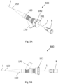
- FIG. 4A A cross-sectional view along a longitudinal axis of a preferred aspect of a cannula hub 8 is illustrated in Figure 4A .
- Figures 4A and 4B are cross-sectional views along a longitudinal axis of an essentially cylindrical or conical cannula hub.
- the cannula hub 8 preferably has a round shape being symmetric in all radial directions, as is also seen in Figures 5A and 5B , from perspective views.
- the internal longitudinal channel 10 of the cannula hub 8 connects the lumen 7 of the proximal part 4 of the cannula to the female connector 13 at the proximal end of the cannula hub 8.
- the female connector 13 may be a standard Luer female connector, or other suitable connector.
- the cannula hub 8 Before use in delivery of a substance, the cannula hub 8 may be provided with a cap or stopper 14, to keep the internal area clean and contaminant free.
- the inner cavity 15 of the cannula hub 8 is preferably adapted for minimal dead volume during delivery when using a standard Luer connector 16, as shown in Figure 4B .
- "Dead volume” is herein used as a term for the volume of e.g. a substance which does not exit the device during delivery, e.g. the volume that remains in the cannula hub (or the system as a whole) after a syringe is pressed into the female connector 13 and a substance 17 is injected via the syringe to the cannula.
- the inner cavity 15 of the cannula hub 8 is configured such that when a standard male Luer connector 16 is connected to the cannula hub it fits tightly along the inner walls of the cavity 15, and a minimal inner volume is present distally of the male connector 16.
- the shape of the inner volume may preferably be as illustrated in Figure 4A and 4B .
- the inner volume of the cannula hub 8 may be formed of a thin cylindrical disc distally of the male connector 16, a cone shaped volume and a narrow cylindrical volume of the inner longitudinal channel 10.
- the dead volume formed by the inner volume of the cannula hub 8 is preferably less than 0,45 ml, preferably within the range of 0,25 ml to 0,45 ml, more preferably between 0,30 ml to 0,40 mm.
- the dead volume of the delivery system as a whole comprises the inner volume of the cannula hub 8, as described above, together with the inner volume of the rest of the cannula 1.
- a small dead volume of the delivery system as seen when a male Luer connector is attached, allows minimal loss of substance during delivery, which is particularly important when delivering expensive and/or rare substances, and minimizes the risk of creating air embolisms.
- the total inner deadspace of the cannula hub 8 and cannula 1 is below 0,50 ml, more preferably below 0,40 ml.
- a further advantage of the particular inner volume shape of the cavity of the cannula hub as shown in Figures 4A and 4b i.e. a thin cylindrical disc transitioning smoothly into the inner longitudinal channel 10 via a short cone shape, is that less turbulence is seen in the solution when injecting the substance. This is of particular importance when using delicate substances such as solutions containing living cells, e.g. stem cells, or other less stable cells or molecules.
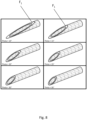
- the cannula 1 and cannula hub 8 are preferably used together with a protective catheter 150 and catheter hub 160.
- a protective catheter 150 and catheter hub 160 are illustrated in Figure 5A , in perspective view, and in Figure 5B , in a side view.
- the protective catheter 150 is integrated with or attached to the catheter hub 160 at the distal end of the catheter hub 160.
- protective catheter 150 is shown in cut-away view; however, it extends to cover the entire cannula 1 to the distal end of the cannula.
- Figure 6A illustrates a cross-sectional view along the longitudinal axis of the catheter hub 160.
- Figure 6B illustrates the catheter hub 160 as shown in Figure 6A with a cannula 1 inserted.
- the cannula 1 is adapted to be inserted from the proximal end of the catheter hub 160 through opening 161.
- a locking means 162 is adapted to be used to lock the cannula 1 in place after insertion of the cannula into the protective catheter 150 and during different stages of the delivery procedure.
- the locking means 162 is in a locked state, all axial movement between the protective catheter 150 and the cannula 1, and thus also the cannula hub 8 and the catheter hub 160, is prevented.
- the cannula 1 is inserted into the catheter 150 via the catheter hub 160 either by the user, or during manufacture of the assembly, such that the distal tip 6 of the cannula 1 is protected by a distal end of the protective catheter 150 (not illustrated).
- the catheter hub 160 may comprise a side port 170, which may be used for flushing the system with saline or other suitable solutions, before, during or after the delivery procedure.
- the catheter hub 160 comprises an internal channel 163 which extends from the proximal opening 161 along the longitudinal axis into the protective catheter 150 at the distal end of the catheter hub 160.
- the internal channel 163 is adapted for insertion of the cannula 1.
- the locking means 162 may comprise any suitable mechanism to be able to lock the cannula in place when inserted into the catheter hub.
- the locking means 162 is adapted to reversibly alternate between a locked state and an unlocked state.
- Non-limiting examples include screw locks, snap locks, friction locks and lever-based locks.
- Figures 5A-5B and 6A-6B show one example of a locking means 162.
- a locking wheel 164 comprising an extension of internal channel 163 is provided.
- Locking wheel 164 is provided with internal threads 165a, which are adapted to collaborate with external threads 165b on the catheter housing.
- a guide catheter is usually placed in a vessel such that the distal end of the guide catheter is as close to the target site as possible.
- the assembly 400 is inserted into the guide catheter 200 and pushed or guided into a position such that the distal end of the catheter 150 protrudes from the guide catheter 200, as seen in Figure 1 .
- the cannula 1 and protective catheter 150 are locked such that axial movement in relation to each other is prevented. This is to inhibit the potentially sharp tip of the cannula 1 from piercing or damaging the guide catheter 200 during insertion, and also to not damage the blood vessel before reaching the desired location.
- the distal end of the assembly 400 is positioned such that the longitudinal axis at the tip of the cannula 1 is directed towards the target site 500, as illustrated. In some aspects, this may be achieved by using a guide catheter 200 with a preshaped bent tip and/or a steerable tip 201, as is known in the art.
- the assembly 400 is advanced distally out of the guide catheter 200.
- the distal tip 6 of the cannula 1 is still contained within the protective catheter 150, to avoid any unintended damage to the vessel.
- locking means 162 of the catheter hub 160 is released, and the tip of the cannula 1 is advanced out of the protective catheter 150 towards the vessel wall and further distally, such that it penetrates the vessel wall and extravascular tissue to reach the target site.
- This movement is performed by moving the proximal cannula hub 8 closer to the proximal end of the catheter hub 160, by e.g. holding the catheter hub 160 still and moving the cannula hub 8 distally.
- a stop element may be provided to prevent premature advancement of the distal tip before reaching a desired location.
- a stop element could be a stop ring or similar arrangement around the cannula 1 between the cannula hub 8 and the catheter hub 160, that may be manually removed before penetration of the vessel wall.
- a marker may be provided on the cannula 1 at a location such that it can be seen between the cannula hub 8 and locking means 162 of the catheter hub 160 when the distal tip 6 of the cannula is protected by the distal tip of the protective catheter 150.
- Such a marker provides a user with a visual indication of when the sharp tip is in a retracted and protected position within the protective catheter, and is useful both during initial positioning of the tip and when repositioning the endoluminal delivery device.
- the cannula 1 and catheter 150 may be locked in a relative axial arrangement, e.g. by engaging locking means 162.
- the procedure may be reversed such that the cannula tip is once more protected by the catheter tip, and thereafter optionally repeated for another delivery dose.
- the distal tip portion 5 is preferably gradually tapered towards the distal tip 6.
- the distal tip portion 5 of the cannula is provided with a pointed tip section 100 for penetrating tissue formed by at least one primary facet F 1 and two secondary facets F 2 and F 3 .
- a pointed tip section 100 for penetrating tissue formed by at least one primary facet F 1 and two secondary facets F 2 and F 3 .
- a tip section is shown on a cannula 1 for delivery of a substance via the vasculature.
- a similar pointed tip for other devices with similar use, such as micro-needles for intramuscular or intradermal injections.
- Figures 7A-7E illustrate the grinding angles used to form the primary and secondary facets.
- the gradual taper of the distal tip portion 5 of the cannula is not visible in Figures 7A-7E , and the following figures, as they schematically illustrate only the final approximate 1-3 millimetres of the tip section 100.
- figures 7A, 7B , 7C and 8 to 11 i.e. when showing a perspective or side view, the left side of the figure is directed generally in the distal direction, and the right side of the figure is directed generally towards the proximal end of the cannula.
- Figure 7D showing a top view of a tip section 100, upwards in the figure corresponds to a distal direction of the tip.
- a tip section 100 is viewed along the longitudinal axis A.
- the distal end of the cannula is ground down and sharpened against a grinding wheel or other grinding media.
- the grinding wheel is stationary, and the needle or cannula is applied at a fixed angle in relation to the grinding surface.
- the resulting facets or bevels are thus formed in one or several planes which may be defined in relation to the geometry of the cannula itself.
- Figure 7A shows a perspective and schematic view of a tip section 100 before grinding of any facets.
- the cylindrical cannula tip section 100 is illustrated to have two reference planes, shown as a first plane P 1 and a second plane P 2 arranged along the longitudinal axis A, wherein the first and second planes P 1 , P 2 are perpendicular to each other.
- These reference planes P 1 , P 2 are herein used to define the angles and placement of the planes defining the facets of the resulting tip section 100.
- the first plane P 1 may be viewed as a horizontal plane and the second plane P 2 may be viewed as a vertical plane.
- Figure 7B illustrates a side view of the tip section 100 shown in Figure 7A after grinding of the facets.
- FIG. 7C A perspective view of the tip section 100 is shown in Figure 7C , wherein the planes forming the facets in relation to the reference planes are illustrated, as will be detailed below.
- the primary facet F 1 of the tip is formed by a needle grinding in a third plane P 3 , wherein the third plane P 3 is positioned at an angle theta ⁇ , in respect to the first plane P 1 , as best seen in Figure 7B .
- the third plane P 3 is symmetrically arranged in relation to the second plane P 2 such that the third plane P 3 intersects the first plane P 1 , in an extension perpendicular to the second plane P 2 .
- a pointed tip 6 is formed in the distal direction. Examples of a resulting tip after the first grinding are shown in Figure 8 and discussed further below.
- Figure 7D illustrates a top view, i.e. as seen from a direction perpendicular to plane P 1 , of the tip section 100 after a first grinding in the third plane P 3 .
- Figure 7E shows the tip section 100 from a distal direction, along the longitudinal axis A.
- the fourth and fifth planes P 4 ,P 5 are arranged at a set of two symmetrical and combined angles, such that the fourth and fifth planes P 4 ,P 5 are symmetrically arranged in relation to the longitudinal axis, and also to the first and second planes P 1 , P 2 .
- the symmetrical angles of the fourth and fifth planes P 4 ,P 5 are thus comprised of two combined angles measured in different planes or views. As seen in Figure 7D , when the tip section 100 is viewed from a top view, or along plane P 2 , a first angle phi (p may be measured on either side of the second plane P 2 in the first plane P 1 .
- the second component of the arrangement of the fourth and fifth planes P 4 ,P 5 is a rotational angle omega ⁇ around longitudinal axis A, as illustrated in Figure 7E.
- Figure 7E illustrates a tip section 100 as seen along the longitudinal axis A.
- the fourth and fifth planes P 4 ,P 5 are defined by rotation in two opposite directions in relation to the reference planes.
- the two angles phi ⁇ and omega ⁇ together describe the arrangement of fourth and fifth planes P 4 ,P 5 , and thus the angles defining the two secondary facets F 2 and F 3 . Examples of several resulting tips after the different grinding steps are shown in Figures 9 and 10 , and are further described in the experimental section below.
- the two secondary facets F 2 , F 3 form the distal tip 6 together with an outer mantle surface of the tip section 100.
- the sharpness of the distal tip may be controlled by both phi ⁇ and omega ⁇ , thereby offering the ability to optimize sharpness and finding the most effective penetration of e.g. a tissue.
- theta must be low, preferably under 30 degrees, to obtain a usable tip at all.
- the tip will have an unsatisfactory rigidity.
- a needle tip section with one primary facet F 1 and two secondary facets F 2 and F 3 is preferably provided at primary facet angle theta ⁇ being between 10.0 and 20.0 degrees, and secondary facets provided at +/- phi ⁇ angles between 15.0 and 20.0 degrees, and +/- omega ⁇ angles between 25.0 and 90.0 degrees.
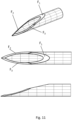
- a needle tip section is shown in Figure 11 , having theta ⁇ angle 12.5 degrees, phi ⁇ angle +/-18.0 degrees, omega angles +/-30.0 degrees.
- a suitable tip section would be a tip having theta ⁇ angle 15.0 degrees, phi ⁇ angle +/-20.0 degrees, omega angles +/-30.0 degrees.
- a tip section 100 works in combination with the overall tapered tip portion 5 of the cannula 1, such that a less-traumatic penetration of a vessel wall may be achieved, mitigating the need to provide any specific closure measures, such as plugging or stopping the hole made by the penetrating tip in the vessel wall.
- FIGS. 8 to 11 The figures illustrating a needle tip ( Figures 8 to 11 ) are based on a catheter having ID (inner diameter) 0.147 mm and OD (outer diameter) 0.190 mm at the distal end, being tapered by a 25 cm long grinding. Based on the dimensions of the catheter, the optimal grinding angles were mathematically modelled to determine low penetration force and low buckling of the needle tip, i.e. rigidity.
- the first grinding angle, theta was evaluated for angles between 10° and 35°. These grinding angles, as illustrated in Figure 8 , yielded a soft, rounded point, which had low vertical rigidity, but good lateral rigidity.
- Facets 2 and 3 can be tilted by rotating the catheter by an angle, omega, as shown in Fig. 7D . Consequently, the catheter was rotated +/- omega when grinding facets 2 and 3 respectively.
- omega was set to 30°, and a series of different geometries was constructed and inspected, after which a domain of good design could be identified.
- Theta ⁇ 10° produced a needle tip with low rigidity. When phi > 45°, the tip will not become sharp.
Landscapes
- Health & Medical Sciences (AREA)
- Life Sciences & Earth Sciences (AREA)
- Public Health (AREA)
- Veterinary Medicine (AREA)
- Biomedical Technology (AREA)
- Heart & Thoracic Surgery (AREA)
- General Health & Medical Sciences (AREA)
- Engineering & Computer Science (AREA)
- Animal Behavior & Ethology (AREA)
- Hematology (AREA)
- Anesthesiology (AREA)
- Surgery (AREA)
- Vascular Medicine (AREA)
- Biophysics (AREA)
- Pulmonology (AREA)
- Nuclear Medicine, Radiotherapy & Molecular Imaging (AREA)
- Medical Informatics (AREA)
- Molecular Biology (AREA)
- Pathology (AREA)
- Infusion, Injection, And Reservoir Apparatuses (AREA)
- Media Introduction/Drainage Providing Device (AREA)
Claims (14)
- Endoluminale Freisetzungskanüle (1) zum Freisetzen einer Substanz an eine extravaskuläre oder intramyokardiale Zielstelle über das Gefäßsystem eines menschlichen oder tierischen Körpers,
wobei die Kanüle (1) ein proximales Ende (2), das dazu konfiguriert ist, außerhalb des Körpers zu bleiben, und ein distales Ende (3), das dazu konfiguriert ist, über das Gefäßsystem in den Körper eingeführt zu werden, um auf die extravaskuläre oder intramyokardiale Zielstelle zuzugreifen, aufweist, wobei die Kanüle (1) eine gesamte Längslänge (L1) von dem proximalen Ende (2) zu dem distalen Ende (3) aufweist und die Kanüle (1) Folgendes umfasst:einen Kanülenansatz (8), der an dem proximalen Ende (2) der Kanüle (1) bereitgestellt ist,einen länglichen proximalen Abschnitt (4), der eine Längslänge (L2) und einen Außendurchmesser (D1) aufweist, wobei der Außendurchmesser (D1) entlang im Wesentlichen der vollständigen Länge des proximalen Abschnitts (4) konstant ist, wie gemessen, wenn die Kanüle im Wesentlichen gerade ist, undeinen Spitzenabschnitt (5), der distal des proximalen Abschnitts (4) angeordnet ist und sich von dem proximalen Abschnitt (4) zu einer distalen Spitze (6) der Kanüle (1) erstreckt, undein kontinuierliches Lumen (7), das sich von dem proximalen Ende (2) der Kanüle durch den proximalen Abschnitt (4) und den Spitzenabschnitt (5) zu der distalen Spitze (6) erstreckt, und wobei das Lumen (7) einen Innendurchmesser (D2) entlang der vollständigen Länge der Kanüle (1) aufweist,wobei der Spitzenabschnitt (5) eine primäre Öffnung (9) an der distalen Spitze (6) aufweist, um Kommunikation zwischen dem Lumen (7) und dem Äußeren der Kanüle (1) bereitzustellen,wobei der Spitzenabschnitt (5) in Richtung der distalen Spitze (6) entlang des vollständigen Spitzenabschnitts (5) von dem distalen Ende des länglichen proximalen Abschnitts (4) zu der distalen Spitze (6) verjüngt ist,wobei der verjüngte Spitzenabschnitt (5) an dem proximalen Ende des Spitzenabschnitts (5) mit einem äußeren Durchmesser (D3), der im Wesentlichen der gleiche wie der äußere Durchmesser (D1) des länglichen proximalen Abschnitts (4) ist, und einem äußeren Durchmesser (D4) an der distalen Spitze, der kleiner als der äußere Durchmesser (D3) an dem proximalen Ende des verjüngten Spitzenabschnitts (5) ist, bereitgestellt ist,wobei der verjüngte Spitzenabschnitt (5) mit einem distalen scharfen Spitzenteil (100) zum Durchdringen von Gewebe bereitgestellt ist,
dadurch gekennzeichnet, dassder verjüngte Spitzenabschnitt (5) eine Längslänge (L3) von mindestens 100 mm, bevorzugt zwischen 100 mm und 300 mm, bevorzugter zwischen 200 mm und 280 mm aufweist,wobei der scharfe Spitzenteil (100) mindestens eine primäre Facette (F1) und zwei sekundäre Facetten (F2, F3) umfasst,wobei die zwei sekundären Facetten (F2, F3) proximal der primären Facette (F1) angeordnet sind undwobei der distale scharfe Spitzenteil (100) ebenfalls ein Lumen (7) aufweist, das eine Fortsetzung des kontinuierlichen Lumens (7) ist. - Endoluminale Freisetzungskanüle (1) nach Anspruch 1, wobei die gesamte Längslänge (L1) von dem proximalen Ende (2) zu dem distalen Ende (3) innerhalb des Bereichs von ungefähr 300 mm bis 2500 mm liegt.
- Endoluminale Freisetzungskanüle (1) nach einem der vorhergehenden Ansprüche, wobei der äußere Durchmesser D4 an der distalen Spitze (6) innerhalb des Bereichs von 0,10 mm bis 0,25 mm und bevorzugt zwischen 0,15 mm bis 0,22 mm liegt.
- Endoluminale Freisetzungskanüle (1) nach einem der vorhergehenden Ansprüche, wobei der verjüngte Spitzenabschnitt (5) und/oder der proximale Abschnitt (4) mit einem oder mehreren strahlenundurchlässigen Markierungsstreifen (11) auf vordefinierten Abständen von der distalen Spitze (6) bereitgestellt ist.
- Endoluminale Freisetzungskanüle (1) nach einem der vorhergehenden Ansprüche, wobei der verjüngte Spitzenabschnitt (5) mit einem oder mehreren hervorstehenden Tiefenbegrenzungselementen (12) bereitgestellt ist.
- Endoluminale Freisetzungskanüle (1) nach einem der vorhergehenden Ansprüche, wobei der verjüngte Spitzenabschnitt (5) ferner mit einer oder mehreren Seitenöffnungen (9') entlang mindestens eines Teils des verjüngten Spitzenabschnitts (5) bereitgestellt ist.
- Endoluminale Freisetzungskanüle (1) nach einem der vorhergehenden Ansprüche, wobei der Kanülenansatz (8) an seinem proximalen Ende mit einem inneren Längskanal (10) und einem Buchsenanschluss (13) bereitgestellt ist, wobei der innere Längskanal (10) dazu konfiguriert ist, Kommunikation zwischen dem kontinuierlichen Lumen (7) der Kanüle und dem Buchsenanschluss (10) bereitzustellen, wobei der innere Längskanal (10) und der Buchsenanschluss (13) zusammen ein gesamtes inneres Volumen aufweisen, das weniger als 0,45 ml beträgt, wenn ein entsprechender Steckanschluss an dem Buchsenanschluss (13) befestigt ist.
- Endoluminale Freisetzungskanüle (1) nach einem der vorhergehenden Ansprüche, wobei der distale Spitzenteil (100) Folgendes aufweist:eine erste Ebene (P1), die entlang einer zentralen Längsachse (A) angeordnet ist, und eine zweite Ebene (P2), die entlang der Längsachse (A) angeordnet ist, wobei die erste und die zweite Ebene (P1, P2) senkrecht zueinander sind, undeine dritte Ebene (P3), die in einem Winkel Theta (θ) in Bezug auf die erste Ebene (P1) positioniert ist, wobei die dritte Ebene (P3) symmetrisch in Bezug auf die zweite Ebene (P2) angeordnet ist, undeine vierte Ebene (P4) und eine fünfte Ebene (P5), die als ein Satz zweier symmetrischer Winkel angeordnet sind, wobei die Winkel in Bezug auf jede der ersten und der zweiten Ebene (P1, P2) symmetrisch sind,wobei die symmetrischen Winkel kombinierte Winkel sind, die einen ersten Winkel Phi (ϕ), wie gemessen von der zweiten Ebene (P2), in der ersten Ebene (P1) und einen zweiten Winkel Omega (ω) umfassen, der ein Drehwinkel um die Längsachse (A) ist, wobeidie primäre Facette (F1) des distalen Spitzenteils (100) in der dritten Ebene (P3) bereitgestellt ist unddie zwei sekundären Facetten (F2, F3) in der vierten beziehungsweise der fünften Ebene (P4, P5) bereitgestellt sind.
- Endoluminale Freisetzungskanüle (1) nach Anspruch 8, wobei die zwei sekundären Facetten (F2, F3) zusammen mit einer äußeren Hüllenfläche des Spitzenteils (100) eine distale Spitze (6) bilden.
- Endoluminale Freisetzungskanüle (1) nach einem der Ansprüche 8 oder 9, wobei der Winkel Phi (ϕ) größer als der Winkel Theta (θ) ist.
- Endoluminale Freisetzungskanüle (1) nach einem der Ansprüche 8 bis 10, wobei die eine primäre Facette (F1) und die zwei sekundären Facetten (F2, F3) in einem primären Facettenwinkel Theta (θ) bereitgestellt werden, der zwischen 10,0 und 20,0 Grad beträgt, und die sekundären Facetten bei +/-Phi-Winkeln, ϕ-Winkeln, zwischen 15,0 und 20,0 Grad und +/-Omega-Winkeln, ω-Winkeln, zwischen 25,0 und 90,0 Grad bereitgestellt werden.
- Endoluminale Freisetzungsanordnung (400) zum Freisetzen einer Substanz an eine extravaskuläre oder intramyokardiale Zielstelle über das Gefäßsystem eines menschlichen oder tierischen Körpers, umfassend:die endoluminale Freisetzungskanüle (1) nach einem der Ansprüche 1 bis 11,einen Schutzkatheter (150) der zum Einführen in das Gefäßsystem eines menschlichen oder tierischen Körpers ausgelegt ist,wobei ein distales Ende der Anordnung dazu konfiguriert ist, an eine Position in dem Gefäßsystem geleitet zu werden, die zum Zugreifen auf die angestrebte extravaskuläre oder intramyokardiale Zielstelle geeignet ist, undeinen proximalen Katheteransatz (160), der an dem proximalen Ende des Schutzkatheters (150) bereitgestellt ist und zum Leiten des Schutzkatheters (150) durch das Gefäßsystem ausgelegt ist, wobei der proximale Katheteransatz (160) darauf ausgelegt ist, dass die endoluminale Freisetzungskanüle (1) dahindurch und in den Schutzkatheter (150) eingeführt wird.
- Endoluminale Freisetzungsanordnung (400) nach Anspruch 12, wobei der Katheteransatz (160) ferner ein Verriegelungsmittel (162) umfasst, das darauf ausgelegt ist, reversibel zwischen einem verriegelten Zustand und einem nichtverriegelten Zustand abzuwechseln, wobei das Verriegelungsmittel (162) dazu konfiguriert ist, in einem verriegelten Zustand eine axiale Bewegung zwischen dem Schutzkatheter (150) und der endoluminalen Freisetzungskanüle (1) zu verhindern.
- Endoluminale Freisetzungsanordnung (400) nach Anspruch 13, wobei das Verriegelungsmittel (162) ein Verriegelungsrad (164) umfasst, das mit inneren Gewinden (165a) bereitgestellt ist, die mit äußeren Gewinden (165b) des Katheteransatzgehäuses zusammenwirken, wobei das Verriegelungsmittel derart ausgelegt ist, dass, wenn das Verriegelungsmittel betätigt wird, eine innere Verriegelungsmanschette (166) zusammengedrückt wird, um ein proximales Ende der endoluminalen Freisetzungskanüle in Eingriff zu nehmen.
Applications Claiming Priority (2)
| Application Number | Priority Date | Filing Date | Title |
|---|---|---|---|
| SE2050580A SE2050580A1 (en) | 2020-05-19 | 2020-05-19 | Endoluminal delivery cannula and assembly |
| PCT/SE2021/050443 WO2021235993A1 (en) | 2020-05-19 | 2021-05-11 | Endoluminal delivery cannula and assembly, and related methods |
Publications (3)
| Publication Number | Publication Date |
|---|---|
| EP4153281A1 EP4153281A1 (de) | 2023-03-29 |
| EP4153281C0 EP4153281C0 (de) | 2024-11-06 |
| EP4153281B1 true EP4153281B1 (de) | 2024-11-06 |
Family
ID=75954240
Family Applications (1)
| Application Number | Title | Priority Date | Filing Date |
|---|---|---|---|
| EP21726234.4A Active EP4153281B1 (de) | 2020-05-19 | 2021-05-11 | Endoluminale freisetzungskanüle und anordnung |
Country Status (7)
| Country | Link |
|---|---|
| US (1) | US20230181179A1 (de) |
| EP (1) | EP4153281B1 (de) |
| JP (1) | JP2023526753A (de) |
| ES (1) | ES3006782T3 (de) |
| PL (1) | PL4153281T3 (de) |
| SE (1) | SE2050580A1 (de) |
| WO (1) | WO2021235993A1 (de) |
Families Citing this family (1)
| Publication number | Priority date | Publication date | Assignee | Title |
|---|---|---|---|---|
| US20220409855A1 (en) * | 2021-06-29 | 2022-12-29 | Staffan Holmin | Methods of delivering cells and therapeutic agents to organs and extravascular sites |
Citations (2)
| Publication number | Priority date | Publication date | Assignee | Title |
|---|---|---|---|---|
| US20050107751A1 (en) * | 2002-03-29 | 2005-05-19 | Terumo Kabushiki Kaisha | Injection needle |
| US20160206832A1 (en) * | 2014-07-08 | 2016-07-21 | Terumo Kabushiki Kaisha | Injection needle |
Family Cites Families (25)
| Publication number | Priority date | Publication date | Assignee | Title |
|---|---|---|---|---|
| US4248234A (en) * | 1979-03-08 | 1981-02-03 | Critikon, Inc. | Catheter with variable flexural modulus and method of using same |
| AU9143982A (en) * | 1982-01-20 | 1983-07-28 | Sorenson Research Co. Inc. | Translating and positioning a catheter |
| US5464395A (en) | 1994-04-05 | 1995-11-07 | Faxon; David P. | Catheter for delivering therapeutic and/or diagnostic agents to the tissue surrounding a bodily passageway |
| US6723082B1 (en) * | 1995-05-10 | 2004-04-20 | Sam G. Payne | Delivery catheter system for heart chamber |
| US5733323A (en) * | 1995-11-13 | 1998-03-31 | Cordis Corporation | Electrically conductive unipolar vascular sheath |
| CA2273467C (en) | 1998-06-04 | 2009-02-17 | Cordis Webster, Inc. | Catheter for injecting therapeutic and diagnostic agents |
| US6613017B1 (en) | 2000-08-08 | 2003-09-02 | Scimed Life Systems, Inc. | Controlled depth injection device and method |
| US8979801B2 (en) * | 2001-01-17 | 2015-03-17 | Medtronic Vascular, Inc. | Microcatheter devices and methods for targeted substance delivery |
| US6835193B2 (en) * | 2001-07-10 | 2004-12-28 | Myocardial Therapeutics, Inc. | Methods for controlled depth injections into interior body cavities |
| US6796963B2 (en) | 2001-07-10 | 2004-09-28 | Myocardial Therapeutics, Inc. | Flexible tissue injection catheters with controlled depth penetration |
| US20040267203A1 (en) * | 2003-06-26 | 2004-12-30 | Potter Daniel J. | Splittable cannula having radiopaque marker |
| US7273469B1 (en) | 2003-12-31 | 2007-09-25 | Advanced Cardiovascular Systems, Inc. | Modified needle catheter for directional orientation delivery |
| EP1990067A3 (de) * | 2006-02-23 | 2010-12-15 | Levitronix LLC | Perfusionskanüle und Blut-Managementsystem |
| WO2010078196A1 (en) * | 2008-12-31 | 2010-07-08 | St. Jude Medical, Atrial Fibrillation Division, Inc. | Fast-acting or rotating transseptal needle |
| WO2012004165A1 (en) * | 2010-07-08 | 2012-01-12 | Karolinska Institutet Innovations Ab | Novel endoluminal medical access device |
| CN102793577A (zh) * | 2011-05-27 | 2012-11-28 | 心诺普医疗技术(北京)有限公司 | 一种心包穿刺针组件 |
| US8852165B2 (en) * | 2011-06-16 | 2014-10-07 | II Edward G. Mackay | Endoluminal drug delivery devices and methods |
| CA2876116A1 (en) * | 2012-06-14 | 2013-12-19 | Asahi Kasei Medical Co., Ltd. | Puncture needle |
| EP3066999A1 (de) * | 2015-03-11 | 2016-09-14 | Richard A. Schatz | Einführbarriere für injektionsnadel |
| US20170035990A1 (en) * | 2015-08-04 | 2017-02-09 | Kevin Swift | Endoluminal fluid delivery device and method |
| US10702292B2 (en) * | 2015-08-28 | 2020-07-07 | Incuvate, Llc | Aspiration monitoring system and method |
| US10173027B2 (en) * | 2015-10-07 | 2019-01-08 | Cook Medical Technologies Llc | Methods, medical devices and kits for modifying the luminal profile of a body vessel |
| JP2017080117A (ja) * | 2015-10-28 | 2017-05-18 | テルモ株式会社 | 医療用穿刺針 |
| US10413707B2 (en) * | 2016-09-02 | 2019-09-17 | Lake Region Manufacturing, Inc. | Transseptal crossing guidewire with faceted piercing head |
| EP3863539A4 (de) * | 2018-10-10 | 2022-06-08 | Merit Medical Systems, Inc. | Teleskopische atriale septumnadel |
-
2020
- 2020-05-19 SE SE2050580A patent/SE2050580A1/en not_active Application Discontinuation
-
2021
- 2021-05-11 JP JP2022563442A patent/JP2023526753A/ja active Pending
- 2021-05-11 EP EP21726234.4A patent/EP4153281B1/de active Active
- 2021-05-11 WO PCT/SE2021/050443 patent/WO2021235993A1/en not_active Ceased
- 2021-05-11 US US17/925,844 patent/US20230181179A1/en active Pending
- 2021-05-11 PL PL21726234.4T patent/PL4153281T3/pl unknown
- 2021-05-11 ES ES21726234T patent/ES3006782T3/es active Active
Patent Citations (2)
| Publication number | Priority date | Publication date | Assignee | Title |
|---|---|---|---|---|
| US20050107751A1 (en) * | 2002-03-29 | 2005-05-19 | Terumo Kabushiki Kaisha | Injection needle |
| US20160206832A1 (en) * | 2014-07-08 | 2016-07-21 | Terumo Kabushiki Kaisha | Injection needle |
Also Published As
| Publication number | Publication date |
|---|---|
| EP4153281A1 (de) | 2023-03-29 |
| PL4153281T3 (pl) | 2025-03-31 |
| US20230181179A1 (en) | 2023-06-15 |
| ES3006782T3 (en) | 2025-03-18 |
| EP4153281C0 (de) | 2024-11-06 |
| JP2023526753A (ja) | 2023-06-23 |
| WO2021235993A1 (en) | 2021-11-25 |
| SE2050580A1 (en) | 2021-11-20 |
Similar Documents
| Publication | Publication Date | Title |
|---|---|---|
| JP7586900B2 (ja) | 患者の血管系にアクセスするためのカテーテルアセンブリ | |
| EP1351646B1 (de) | Vorrichtung zur myokardialen Revaskularisation | |
| US8568435B2 (en) | Transvascular retrograde access devices | |
| US8114110B2 (en) | Transseptal puncture needle and needle assemblies | |
| US7022109B1 (en) | Pain abatement catheter system | |
| US8628491B2 (en) | Transjugular intrahepatic portosystemic shunt device | |
| US20100160731A1 (en) | Ultrasound-visualizable endoscopic access system | |
| US20050149097A1 (en) | Transseptal needle | |
| US20070135681A1 (en) | Flexible needle | |
| US12303662B2 (en) | Injection devices and systems and methods for using them | |
| US20170112528A1 (en) | Echogenic needle assemblies and method of use thereof | |
| CN101495171A (zh) | 用于穿过脉管系统中的完全闭塞的导管系统 | |
| WO2020014295A1 (en) | Vascular access needle for guidewire insertion | |
| US20130116556A1 (en) | Neural safety injection system and related methods | |
| EP4153281B1 (de) | Endoluminale freisetzungskanüle und anordnung | |
| US9072596B1 (en) | Transjugular intrahepatic portosystemic shunt device | |
| HK40088181B (en) | Endoluminal delivery cannula and assembly | |
| HK40088181A (en) | Endoluminal delivery cannula and assembly | |
| WO2023278382A1 (en) | Endoluminal delivery cannula | |
| WO2016179280A1 (en) | Hybrid needle system for central venous access | |
| CN121154220B (zh) | 用于卵圆孔未闭介入封堵器导丝的导引系统 | |
| EP2994177A1 (de) | Transjuguläre intrahepatische portosystemische shunt-vorrichtung | |
| US20250256124A1 (en) | System and method for high pressure delivery of radioactive material for cancer therapy | |
| EP2740422A1 (de) | Neurales Sicherheitsinjektionssystem und zugehörige Verfahren | |
| CA2797922A1 (en) | Safety neural injection system and related methods |
Legal Events
| Date | Code | Title | Description |
|---|---|---|---|
| STAA | Information on the status of an ep patent application or granted ep patent |
Free format text: STATUS: UNKNOWN |
|
| STAA | Information on the status of an ep patent application or granted ep patent |
Free format text: STATUS: THE INTERNATIONAL PUBLICATION HAS BEEN MADE |
|
| PUAI | Public reference made under article 153(3) epc to a published international application that has entered the european phase |
Free format text: ORIGINAL CODE: 0009012 |
|
| STAA | Information on the status of an ep patent application or granted ep patent |
Free format text: STATUS: REQUEST FOR EXAMINATION WAS MADE |
|
| 17P | Request for examination filed |
Effective date: 20221021 |
|
| AK | Designated contracting states |
Kind code of ref document: A1 Designated state(s): AL AT BE BG CH CY CZ DE DK EE ES FI FR GB GR HR HU IE IS IT LI LT LU LV MC MK MT NL NO PL PT RO RS SE SI SK SM TR |
|
| DAV | Request for validation of the european patent (deleted) | ||
| DAX | Request for extension of the european patent (deleted) | ||
| REG | Reference to a national code |
Ref country code: HK Ref legal event code: DE Ref document number: 40088181 Country of ref document: HK |
|
| STAA | Information on the status of an ep patent application or granted ep patent |
Free format text: STATUS: EXAMINATION IS IN PROGRESS |
|
| 17Q | First examination report despatched |
Effective date: 20240123 |
|
| GRAP | Despatch of communication of intention to grant a patent |
Free format text: ORIGINAL CODE: EPIDOSNIGR1 |
|
| STAA | Information on the status of an ep patent application or granted ep patent |
Free format text: STATUS: GRANT OF PATENT IS INTENDED |
|
| RIC1 | Information provided on ipc code assigned before grant |
Ipc: A61M 25/00 20060101ALI20240704BHEP Ipc: A61B 17/34 20060101ALI20240704BHEP Ipc: A61M 5/32 20060101AFI20240704BHEP |
|
| INTG | Intention to grant announced |
Effective date: 20240724 |
|
| GRAS | Grant fee paid |
Free format text: ORIGINAL CODE: EPIDOSNIGR3 |
|
| GRAA | (expected) grant |
Free format text: ORIGINAL CODE: 0009210 |
|
| STAA | Information on the status of an ep patent application or granted ep patent |
Free format text: STATUS: THE PATENT HAS BEEN GRANTED |
|
| AK | Designated contracting states |
Kind code of ref document: B1 Designated state(s): AL AT BE BG CH CY CZ DE DK EE ES FI FR GB GR HR HU IE IS IT LI LT LU LV MC MK MT NL NO PL PT RO RS SE SI SK SM TR |
|
| REG | Reference to a national code |
Ref country code: GB Ref legal event code: FG4D |
|
| REG | Reference to a national code |
Ref country code: CH Ref legal event code: EP |
|
| REG | Reference to a national code |
Ref country code: DE Ref legal event code: R096 Ref document number: 602021021416 Country of ref document: DE |
|
| REG | Reference to a national code |
Ref country code: IE Ref legal event code: FG4D |
|
| U01 | Request for unitary effect filed |
Effective date: 20241118 |
|
| U07 | Unitary effect registered |
Designated state(s): AT BE BG DE DK EE FI FR IT LT LU LV MT NL PT RO SE SI Effective date: 20241202 |
|
| REG | Reference to a national code |
Ref country code: ES Ref legal event code: FG2A Ref document number: 3006782 Country of ref document: ES Kind code of ref document: T3 Effective date: 20250318 |
|
| PG25 | Lapsed in a contracting state [announced via postgrant information from national office to epo] |
Ref country code: IS Free format text: LAPSE BECAUSE OF FAILURE TO SUBMIT A TRANSLATION OF THE DESCRIPTION OR TO PAY THE FEE WITHIN THE PRESCRIBED TIME-LIMIT Effective date: 20250306 Ref country code: HR Free format text: LAPSE BECAUSE OF FAILURE TO SUBMIT A TRANSLATION OF THE DESCRIPTION OR TO PAY THE FEE WITHIN THE PRESCRIBED TIME-LIMIT Effective date: 20241106 |
|
| PG25 | Lapsed in a contracting state [announced via postgrant information from national office to epo] |
Ref country code: NO Free format text: LAPSE BECAUSE OF FAILURE TO SUBMIT A TRANSLATION OF THE DESCRIPTION OR TO PAY THE FEE WITHIN THE PRESCRIBED TIME-LIMIT Effective date: 20250206 |
|
| PG25 | Lapsed in a contracting state [announced via postgrant information from national office to epo] |
Ref country code: GR Free format text: LAPSE BECAUSE OF FAILURE TO SUBMIT A TRANSLATION OF THE DESCRIPTION OR TO PAY THE FEE WITHIN THE PRESCRIBED TIME-LIMIT Effective date: 20250207 |
|
| PGFP | Annual fee paid to national office [announced via postgrant information from national office to epo] |
Ref country code: GB Payment date: 20250318 Year of fee payment: 5 |
|
| PG25 | Lapsed in a contracting state [announced via postgrant information from national office to epo] |
Ref country code: RS Free format text: LAPSE BECAUSE OF FAILURE TO SUBMIT A TRANSLATION OF THE DESCRIPTION OR TO PAY THE FEE WITHIN THE PRESCRIBED TIME-LIMIT Effective date: 20250206 |
|
| U20 | Renewal fee for the european patent with unitary effect paid |
Year of fee payment: 5 Effective date: 20250324 |
|
| PG25 | Lapsed in a contracting state [announced via postgrant information from national office to epo] |
Ref country code: SM Free format text: LAPSE BECAUSE OF FAILURE TO SUBMIT A TRANSLATION OF THE DESCRIPTION OR TO PAY THE FEE WITHIN THE PRESCRIBED TIME-LIMIT Effective date: 20241106 |
|
| PGFP | Annual fee paid to national office [announced via postgrant information from national office to epo] |
Ref country code: PL Payment date: 20250425 Year of fee payment: 5 |
|
| PGFP | Annual fee paid to national office [announced via postgrant information from national office to epo] |
Ref country code: CH Payment date: 20250601 Year of fee payment: 5 |
|
| PG25 | Lapsed in a contracting state [announced via postgrant information from national office to epo] |
Ref country code: SK Free format text: LAPSE BECAUSE OF FAILURE TO SUBMIT A TRANSLATION OF THE DESCRIPTION OR TO PAY THE FEE WITHIN THE PRESCRIBED TIME-LIMIT Effective date: 20241106 |
|
| PG25 | Lapsed in a contracting state [announced via postgrant information from national office to epo] |
Ref country code: CZ Free format text: LAPSE BECAUSE OF FAILURE TO SUBMIT A TRANSLATION OF THE DESCRIPTION OR TO PAY THE FEE WITHIN THE PRESCRIBED TIME-LIMIT Effective date: 20241106 |
|
| PGFP | Annual fee paid to national office [announced via postgrant information from national office to epo] |
Ref country code: IE Payment date: 20250415 Year of fee payment: 5 |
|
| PLBE | No opposition filed within time limit |
Free format text: ORIGINAL CODE: 0009261 |
|
| STAA | Information on the status of an ep patent application or granted ep patent |
Free format text: STATUS: NO OPPOSITION FILED WITHIN TIME LIMIT |
|
| PGFP | Annual fee paid to national office [announced via postgrant information from national office to epo] |
Ref country code: ES Payment date: 20250828 Year of fee payment: 5 |
|
| 26N | No opposition filed |
Effective date: 20250807 |
|
| PG25 | Lapsed in a contracting state [announced via postgrant information from national office to epo] |
Ref country code: MC Free format text: LAPSE BECAUSE OF FAILURE TO SUBMIT A TRANSLATION OF THE DESCRIPTION OR TO PAY THE FEE WITHIN THE PRESCRIBED TIME-LIMIT Effective date: 20241106 |