EP4152855A1 - Direktzugriffssignalübertragungsverfahren und endgerät - Google Patents
Direktzugriffssignalübertragungsverfahren und endgerät Download PDFInfo
- Publication number
- EP4152855A1 EP4152855A1 EP21803948.5A EP21803948A EP4152855A1 EP 4152855 A1 EP4152855 A1 EP 4152855A1 EP 21803948 A EP21803948 A EP 21803948A EP 4152855 A1 EP4152855 A1 EP 4152855A1
- Authority
- EP
- European Patent Office
- Prior art keywords
- fixed frame
- frame period
- random access
- pdcch
- time range
- Prior art date
- Legal status (The legal status is an assumption and is not a legal conclusion. Google has not performed a legal analysis and makes no representation as to the accuracy of the status listed.)
- Pending
Links
Images


Classifications
-
- H—ELECTRICITY
- H04—ELECTRIC COMMUNICATION TECHNIQUE
- H04W—WIRELESS COMMUNICATION NETWORKS
- H04W72/00—Local resource management
- H04W72/04—Wireless resource allocation
- H04W72/044—Wireless resource allocation based on the type of the allocated resource
- H04W72/0446—Resources in time domain, e.g. slots or frames
-
- H—ELECTRICITY
- H04—ELECTRIC COMMUNICATION TECHNIQUE
- H04W—WIRELESS COMMUNICATION NETWORKS
- H04W74/00—Wireless channel access
- H04W74/002—Transmission of channel access control information
-
- H—ELECTRICITY
- H04—ELECTRIC COMMUNICATION TECHNIQUE
- H04W—WIRELESS COMMUNICATION NETWORKS
- H04W74/00—Wireless channel access
- H04W74/08—Non-scheduled access, e.g. ALOHA
- H04W74/0833—Random access procedures, e.g. with 4-step access
-
- H—ELECTRICITY
- H04—ELECTRIC COMMUNICATION TECHNIQUE
- H04W—WIRELESS COMMUNICATION NETWORKS
- H04W74/00—Wireless channel access
- H04W74/002—Transmission of channel access control information
- H04W74/006—Transmission of channel access control information in the downlink, i.e. towards the terminal
-
- H—ELECTRICITY
- H04—ELECTRIC COMMUNICATION TECHNIQUE
- H04W—WIRELESS COMMUNICATION NETWORKS
- H04W74/00—Wireless channel access
- H04W74/08—Non-scheduled access, e.g. ALOHA
- H04W74/0808—Non-scheduled access, e.g. ALOHA using carrier sensing, e.g. carrier sense multiple access [CSMA]
-
- H—ELECTRICITY
- H04—ELECTRIC COMMUNICATION TECHNIQUE
- H04W—WIRELESS COMMUNICATION NETWORKS
- H04W74/00—Wireless channel access
- H04W74/08—Non-scheduled access, e.g. ALOHA
- H04W74/0833—Random access procedures, e.g. with 4-step access
- H04W74/0836—Random access procedures, e.g. with 4-step access with 2-step access
Definitions
- Embodiments of the present invention relate to the field of wireless communication technologies, and in particular, to a random access signal transmission method and a terminal.
- a new radio (New Radio, NR) system run at an unlicensed band may be run in a frame-based channel access (FBE channel access) mode.
- FBE channel access frame-based channel access
- FFP Fixed Frame Period
- Embodiments of the present invention provide a random access signal transmission method and a terminal, to resolve a problem that a random access signal cannot be transmitted due to lack of downlink signal configuration or insufficient time for processing a downlink signal within the fixed frame period, affecting access performance of a system.
- an embodiment of the present invention provides a random access signal transmission method, applied to a terminal, the method including:
- an embodiment of the present invention further provides a terminal, including:
- an embodiment of the present invention provides a terminal, including a processor, a memory, and a computer program stored in the memory and executable by the processor, the computer program, when executed by the processor, implementing the steps of the random access signal transmission method according to the first aspect.
- an embodiment of the present invention provides a computer-readable storage medium, the computer-readable storage medium storing a computer program, the computer program, when executed by a processor, implementing the steps of the random access signal transmission according to the first aspect.
- an embodiment of the present invention provides a computer software product, the computer software product being stored in a non-volatile storage medium and being configured to be executed by at least one processor to implement the steps of the random access signal transmission method according to the first aspect.
- a target time range may be determined according to a target downlink signal within a fixed frame period, and a random access channel (RACH) occasion intersected with the target time range within the fixed frame period may be determined as an invalid random access channel (RACH) occasion that is not used for mapping with a synchronization signal and PBCH block, which can avoid the problem that a random access signal cannot be transmitted due to lack of downlink signal configuration or insufficient time for processing a downlink signal within the fixed frame period, affecting access performance of a system.
- RACH random access channel
- the term such as “exemplarily” or “for example” is used to represent giving an example, an illustration, or a description. Any embodiment or design scheme described as an “exemplarily” or “for example” in the embodiments of the present invention should not be explained as being more preferred or having more advantages than another embodiment or design scheme. Exactly, the term such as “exemplarily” or “for example” is intended to present a related concept in a specific manner.
- the wireless communication system may be a 5 th generation system (5 th Generation, 5G), an evolved long term evolution (Evolved Long Term Evolution, eLTE) system, or a subsequent evolution communication system.
- 5G 5 th Generation
- eLTE evolved long term evolution
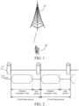
- FIG. 1 is a schematic architectural diagram of a wireless communication system according to an embodiment of the present invention.
- the wireless communication system may include: a network side device 11 and a terminal 12, where the terminal 12 may be connected to the network side device 11.
- connections between the foregoing devices may be wireless connections.
- solid lines are used for illustration in FIG. 1 .
- the foregoing communication system may include a plurality of terminals 12, and the network side device 11 may further communicate (transmit signaling or data) with the plurality of terminals 12.
- the network side device 11 provided in this embodiment of the present invention may be a base station.
- the base station may be a base station.
- the base station may be a commonly used base station, or may be an evolved node base station (evolved node base station, eNB), or may be a network side device (for example, a next generation node base station (next generation node base station, gNB) or a transmission and reception point (transmission and reception point, TRP) or a cell in a 5G system, or may be a network side device in a subsequent evolution communication system.
- eNB evolved node base station
- gNB next generation node base station
- TRP transmission and reception point
- the terminal 12 provided in this embodiment of the present invention may be a mobile phone, a tablet computer, a notebook computer, an ultra-mobile personal computer (Ultra-Mobile Personal Computer, UMPC), a netbook, a personal digital assistant (Personal Digital Assistant, PDA), or the like.
- UMPC Ultra-Mobile Personal Computer
- PDA Personal Digital Assistant
- an unlicensed band may be used as a supplement to a licensed band (Licensed Band) to help an operator expand services.
- the unlicensed band is shared by a plurality of radio access technologies (Radio Access Technologies, RATs) such as Wireless Fidelity (Wireless Fidelity, Wi-Fi), radar, LTE-LAA (License Assisted Access), and the like. Therefore, in some countries or regions, the use of the unlicensed band needs to comply with regulatory regulations to ensure that all devices can fairly share the resource.
- a transmitting node needs to transmit information
- listen before talk (Listen Before Talk, LBT) is first required to be performed on a designated radio channel to perform energy detection (Energy Detection, ED) on a surrounding wireless transmission environment.
- the channel is determined to be idle in a case that energy is lower than a certain threshold, and transmission may be performed in this case. Otherwise, the channel is determined to be busy in a case that the energy is higher than a certain threshold, and the transmission node cannot perform transmission in this case.
- the transmitting device may be a base station, a user equipment (User Equipment, UE), a Wi-Fi access point (Access Point, AP), and the like. After the transmitting node starts to perform transmission, a time occupied by the channel cannot exceed a maximum channel occupancy time (Maximum Channel Occupancy Time, MCOT).
- MCOT maximum Channel Occupancy Time
- a frame based equipment means that transmission/reception by the equipment regularly adopts a periodic structure with a period of a fixed frame period (Fixed Frame Period).
- An FBE node occupies a channel by using an LBT-based channel access mechanism.
- a node that initiates a transmission sequence including one or more times of consecutive transmission is referred to as an initiating node (Initiating Device), and other devices are referred to as responding nodes (Responding Device).
- the FBE node may be an initiating node, a responding node, or a node simultaneously supporting two node functions.
- operation requirements include:
- the responding node may perform the following operations:
- the responding node In a case that the responding node initiates transmission with a maximum interval of 16 ⁇ s after the last authorized transmission instructed by the initiating node is performed, the responding node does not need to perform CCA before transmission, or otherwise, CCA is performed before the beginning of the authorized transmission.
- Authorization is discarded in a case that the channel is determined to be busy, or otherwise, transmission may be initiated on the designated channel, where the channel may occupy a remaining part of the COT within a current fixed frame period at most, transmission may be initiated for a plurality times as long as each time interval between adjacent transmissions does not exceed 16 ⁇ s, and the authorization is discarded after transmission is completed.
- system information transmitted by the base station may be configured as an FBE channel access (that is, semi-static channel access) mode.
- FBE channel access that is, semi-static channel access
- the terminal needs to confirm that downlink transmission is detected within the fixed frame period, or otherwise transmission cannot be performed.
- a plurality of random access channel (RACH) occasions (Random Access Channel (RACH) Occasions, ROs) are configured within a fixed frame period, and such ROs needs to map with corresponding synchronization signal and PBCH blocks (Synchronization Signal and PBCH blocks, SSBs) according to a current technical solution.
- RACH Random Access Channel
- PBCH blocks Synchronization Signal and PBCH blocks, SSBs
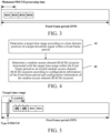
- an embodiment of the present invention provides a random access signal transmission method, applied to a terminal, the method including: Step 41: Determine a target time range according to a time domain position of a target downlink signal within a fixed frame period.
- Step 42 Determine a random access channel (RACH) occasion intersected with the target time range within the fixed frame period as an invalid random access channel (RACH) occasion according to configuration information of the fixed frame period and configuration information of the random access channel (RACH) occasion.
- RACH random access channel
- the invalid random access channel (RACH) occasion is not used for mapping with the synchronization signal and PBCH block, and therefore, is not used for transmission of the random access signal.
- the invalid random access channel (RACH) occasion does not map with a channel state information reference signal.
- a target time range may be determined according to a target downlink signal within a fixed frame period.
- a random access channel (RACH) occasion is configured within the fixed frame period
- a random access channel (RACH) occasion intersected (which is overlapped in a time domain) with the target time range may be determined as an invalid random access channel (RACH) occasion that is not used for mapping with a synchronization signal and PBCH block, which can avoid the problem that a random access signal cannot be transmitted due to lack of downlink signal configuration or insufficient time for processing a downlink signal within the fixed frame period, affecting access performance of a system.
- the random access signal transmission method further includes:
- the valid random access channel (RACH) occasion maps with the channel state information reference signal.
- the target downlink signal in the foregoing embodiments may be of various types, which is described below by using examples.
- a time domain position of the PDCCH and/or the synchronization signal and PBCH block may be determined according to configuration information of the PDCCH and/or configuration information of the synchronization signal and PBCH block, thereby determining the target time range.
- X is predefined, configured according to system information, or configured by Radio Resource Control (Radio Resource Control, RRC). X is related to a time for processing the target downlink signal.
- RRC Radio Resource Control
- the PDCCH is a PDCCH of a common search space type.
- the PDCCH includes one or more of the following: a Type 0 PDCCH, a Type 0A PDCCH, a Type 1 PDCCH, a Type 2 PDCCH, or a Type 3 PDCCH.
- a Type 0 PDCCH a Type 0 PDCCH
- a Type 0A PDCCH a Type 1 PDCCH
- a Type 2 PDCCH a Type 3 PDCCH.
- the foregoing first PDCCH is the first Type 0 PDCCH in this case.
- the first PDCCH is the first Type 0 PDCCH, Type 0A PDCCH, or Type 1 PDCCH that appears.
- the random access signal transmission method further includes: determining that all random access channel (RACH) occasions within the fixed frame period are invalid random access channel (RACH) occasions in a case that the target downlink signal does not exist within the fixed frame period.
- RACH random access channel
- the target downlink signal is a downlink signal on an initial (initial) bandwidth part (Bandwidth Part, BWP) or a BWP including the initial BWP.
- BWP Bandwidth Part
- an existing PDCCH and/or SSB is used as the target downlink signal to determine whether the random access channel (RACH) occasion is invalid, and configuration for detecting the downlink signal is not additionally introduced. In this way, a relatively slight change is made to the system, and implementation is easy.
- the target downlink signal is a first downlink detection signal transmitted within initial Y resource elements of the fixed frame period configured with the random access channel (RACH) occasion, the resource element being a symbol or a slot.
- RACH random access channel
- the method before the determining a target time range according to a time domain position of a target downlink signal within a fixed frame period, the method further includes:
- the time domain position of the first downlink detection signal may be implicitly determined according to the configuration information of the fixed frame period and the configuration information of the random access channel (RACH) occasion.
- Y is predefined, configured according to system information, or configured by RRC.
- the target time range is at least one of the following:
- X is predefined, configured according to system information, or configured by RRC. X is related to a time for processing the target downlink signal.
- the first downlink detection signal includes at least one of the following:
- the predefined sequence is one of the following: a primary synchronization signal (Primary Synchronization Signal, PSS), a secondary synchronization signal (Secondary Synchronization Signal, SSS), a channel state information reference signal (Channel State Information Reference Signal, CSI-RS), or a wideband (wideband)-demodulation reference signal (demodulation reference signal, DM-RS).
- PSS Primary Synchronization Signal
- SSS Secondary Synchronization Signal
- SSS Secondary Synchronization Signal
- CSI-RS Channel State Information Reference Signal
- DM-RS wideband-demodulation reference signal
- the first downlink detection signal does not carry any information or carries information related to a random access channel.
- the random access signal includes a random access pilot or a physical uplink shared channel (Physical Uplink Shared Channel, PUSCH) in MsgA in a 2-step random access procedure.
- PUSCH Physical Uplink Shared Channel
- a dedicated target downlink signal is newly defined to determine whether a random access channel (RACH) occasion within the fixed frame period is invalid, and the target signal is a dedicated signal. In this way, it may be ensured that a downlink signal is existed within each fixed frame period in which the random access channel (RACH) occasion is configured.
- the terminal determines a time domain position of a first common PDCCH within a fixed frame period according to configuration information of a common search space
- the target time range is X symbols after an end time of a control resource set associated with a Type 0 PDCCH search space within a fixed frame period (FFP).
- FFP fixed frame period
- the terminal determines time domain positions (RO1, RO2, RO3, and RO4) of random access channel (RACH) occasions according to configuration information of the random access channel (RACH) occasions in the system information, and determines random access channel (RACH) occasions intersected with the target time range as invalid random access channel (RACH) occasions (such as RO1 and RO2), where the random access channel (RACH) occasions do not map with synchronization signal and PBCH blocks (SSBs).
- the invalid random access channel (RACH) occasion does not map with a channel state information reference signal.
- the terminal determines a fixed frame period (FFP) configured with a random access channel (RACH) occasion according to the configuration information of the fixed frame period and the configuration information of the random access channel (RACH) occasion in the system information, and receives a predefined downlink detection signal (such as the GC-PDCCH) within previous Y symbols (symbols) of the fixed frame period configured with the random access channel (RACH) occasion, thereby determining that the target time range is X symbols after an end time of the downlink detection signal.
- FTP fixed frame period
- RACH random access channel
- the terminal determines time domain positions (RO1, RO2, RO3, and RO4) of random access channel (RACH) occasions according to configuration information of the random access channel (RACH) occasions in the system information, and determines a random access channel (RACH) occasion intersected with the target time range as an invalid random access channel (RACH) occasion (such as RO1), where the random access channel (RACH) occasion does not map with a synchronization signal and PBCH block (SSB).
- the invalid random access channel (RACH) occasion does not map with a channel state information reference signal.
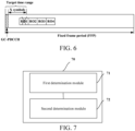
- FIG. 7 is a schematic structural diagram of a terminal according to an embodiment of the present invention.
- the terminal includes:
- a target time range may be determined according to a target downlink signal within a fixed frame period, and a random access channel (RACH) occasion intersected with the target time range within the fixed frame period may be determined as an invalid random access channel (RACH) occasion that is not used for mapping with a synchronization signal and PBCH block, which can avoid the problem that a random access signal cannot be transmitted due to lack of downlink signal configuration or insufficient time for processing a downlink signal within the fixed frame period, affecting access performance of a system.
- RACH random access channel
- the invalid random access channel (RACH) occasion does not map with a channel state information reference signal.
- the terminal provided in this embodiment of the present invention further includes:
- the valid random access channel (RACH) occasion maps with the channel state information reference signal.
- the target downlink signal includes at least one of the following: a physical downlink control channel PDCCH or a synchronization signal and PBCH block.
- the target time range is at least one of the following:
- the PDCCH includes one or more of the following: a Type 0 PDCCH, a Type 0A PDCCH, a Type 1 PDCCH, a Type 2 PDCCH, or a Type 3 PDCCH.
- the terminal provided in this embodiment of the present invention further includes: a fourth determination module, configured to determine that all random access channel (RACH) occasions within the fixed frame period are invalid random access channel (RACH) occasions in a case that the target downlink signal does not exist within the fixed frame period.
- a fourth determination module configured to determine that all random access channel (RACH) occasions within the fixed frame period are invalid random access channel (RACH) occasions in a case that the target downlink signal does not exist within the fixed frame period.
- the target downlink signal is a first downlink detection signal transmitted within initial Y resource elements of the fixed frame period configured with the random access channel (RACH) occasion, the resource element being a symbol or a slot.
- RACH random access channel
- the terminal provided in this embodiment of the present invention further includes:
- Y is predefined, configured according to system information, or configured by RRC.
- the target time range is at least one of the following:
- X is predefined, configured according to system information, or configured by RRC.
- the first downlink detection signal includes at least one of the following:
- the predefined sequence is one of the following: a primary synchronization signal, a secondary synchronization signal, a channel state information reference signal, or a wideband-dedicated demodulation reference signal.
- the first downlink detection signal does not carry any information or carries information related to a random access channel.
- the target downlink signal is a downlink signal on an initial BWP or a BWP including the initial BWP.
- the random access signal includes a random access pilot or a PUSCH in MsgA in a 2-step random access procedure.
- the terminal provided in the embodiments of the present invention can implement the processes implemented by the terminal in the method embodiment of FIG. 4 . To avoid repetition, details are not described herein again.
- FIG. 8 is a schematic structural diagram of hardware of a terminal configured to implement the embodiments of the present invention.
- the terminal 80 includes, but is not limited to, components such as a radio frequency unit 81, a network module 82, an audio output unit 83, an input unit 84, a sensor 85, a display unit 86, a user input unit 87, an interface unit 88, a memory 89, a processor 810, and a power source 811.
- a radio frequency unit 81 such as a radio frequency unit 81, a network module 82, an audio output unit 83, an input unit 84, a sensor 85, a display unit 86, a user input unit 87, an interface unit 88, a memory 89, a processor 810, and a power source 811.
- a person skilled in the art may understand that the terminal structure shown in FIG. 1 constitutes no limitation on the terminal, and the terminal may include more or fewer components than those shown in the figure, or some components may be combined, or a
- the terminal in the embodiments of the present invention includes, but is not limited to, a mobile phone, a tablet computer, a notebook computer, a palmtop computer, an in-vehicle terminal, a wearable device, a pedometer, and the like.
- the processor 810 is configured to determine a target time range according to a time domain position of a target downlink signal within a fixed frame period; and determine a random access channel (RACH) occasion intersected with the target time range within the fixed frame period as an invalid random access channel (RACH) occasion according to configuration information of the fixed frame period and configuration information of the random access channel (RACH) occasion.
- RACH random access channel
- a target time range may be determined according to a target downlink signal within a fixed frame period, and a random access channel (RACH) occasion intersected with the target time range within the fixed frame period may be determined as an invalid random access channel (RACH) occasion that is not used for mapping with a synchronization signal and PBCH block, which can avoid the problem that a random access signal cannot be transmitted due to lack of downlink signal configuration or insufficient time for processing a downlink signal within the fixed frame period, affecting access performance of a system.
- RACH random access channel
- the terminal provided in the embodiments of the present invention can implement the processes implemented by the terminal in the method embodiment of FIG. 4 . To avoid repetition, details are not described herein again.
- the radio frequency unit 81 may be configured to send and receive a signal in an information receiving and sending process or a call process. Specifically, the radio frequency unit receives downlink data from a base station, and then delivers the downlink data to the processor 810 for processing; and in addition, sends uplink data to the base station.
- the radio frequency unit 81 includes, but is not limited to, an antenna, at least one amplifier, a transceiver, a coupler, a low noise amplifier, a duplexer, and the like.
- the radio frequency unit 81 may further communicate with another device through a wireless communication system and a network.
- the terminal provides wireless broadband Internet access for a user by using the network module 82, for example, allowing the user to send and receive emails, browse webpages, access streaming media content, and so on.
- the audio output unit 83 may convert audio data received by the RF unit 81 or the network module 82 or stored in the memory 89 into an audio signal and output the audio signal as a sound.
- the audio output unit 83 may provide an audio output (such as a call signal receiving sound or a message receiving sound) related to a specific function executed by the terminal 80.
- the audio output unit 83 includes a speaker, a buzzer, a receiver, and the like.
- the input unit 84 is configured to receive an audio or video signal.
- the input unit 84 may include a graphics processing unit (Graphics Processing Unit, GPU) 841 and a microphone 842.
- the graphics processing unit 841 performs processing on image data of a static picture or a video acquired by an image acquisition device (for example, a camera) in a video acquisition mode or an image acquisition mode.
- the processed image frame can be displayed on the display unit 86.
- An image frame processed by the graphics processing unit 841 may be stored in the memory 89 (or another storage medium) or sent by using the radio frequency unit 81 or the network module 82.
- the microphone 842 may receive a sound and can process such a sound into audio data.
- the processed audio data may be converted, in a phone call mode, into a format that may be sent by the radio frequency unit 81 to a mobile communication base station.
- the terminal 80 further includes at least one sensor 85 such as an optical sensor, a motion sensor, and another sensor.
- the optical sensor includes an ambient light sensor and a proximity sensor.
- the ambient light sensor may adjust luminance of a display panel 861 according to the luminance of ambient light
- the proximity sensor may switch off the display panel 861 and backlight when the terminal 80 is moved to an ear.
- an acceleration sensor may detect magnitude of accelerations in various directions (generally on three axes), and detect the magnitude and direction of gravity at rest.
- the acceleration sensor is configured to recognize the attitude of the terminal (for example, switching between landscape orientation and portrait orientation, related gaming, and magnetometer attitude calibration), a function related to vibration recognition (such as a pedometer and a knock), and the like.
- the sensor 85 may further include a fingerprint sensor, a pressure sensor, an iris sensor, a molecular sensor, a gyroscope, a barometer, a hygrometer, a thermometer, an infrared sensor, and the like, which will not be described in detail herein.
- the display unit 86 is configured to display information inputted by the user or information to be presented to the user.
- the display unit 86 may include a display panel 861.
- the display panel 861 may be configured in a form of a liquid crystal display (Liquid Crystal Display, LCD), an organic light-emitting diode (Organic Light-Emitting Diode, OLED), or the like.
- the user input unit 87 is configured to receive inputted digital or character information, and generate a key signal input related to user settings and function control of the terminal.
- the user input unit 87 may include a touch panel 871 and other input devices 872.
- the touch panel 871 also referred to as a touch screen, is configured to collect a touch operation made by the user on or in proximity to the touch panel 871 (e.g., an operation made by the user through any appropriate object or attachment (e.g., finger or stylus) on or in proximity to the touch panel 871).
- the touch panel 871 may include a touch detection apparatus and a touch controller.
- the touch detection apparatus is configured to detect a touch position of the user and a signal generated due to the touch operation, and transmit the signal to the touch controller.
- the touch controller is configured to receive touch information from the touch detection apparatus, convert the touch information into coordinates of a touch point, transmit the coordinates to the processor 810, and receive and execute a command sent from the processor 810.
- the touch panel 871 may be of a resistive type, a capacitive type, an infrared type, or a surface acoustic wave type.
- the user input unit 87 may further include the another input device 872.
- the other input devices 872 include, but not limited to, a physical keyboard, a functional button (such as a volume control button or an on/off button), a trackball, a mouse, and a joystick, which will not be described in detail herein.
- the touch panel 871 may cover the display panel 861.
- the touch panel 871 transmits the touch information to the processor 810 so as to determine a type of a touch event. Then, the processor 810 provides a corresponding visual output on the display panel 861 in accordance with the type of the touch event.
- the touch panel 871 and the display panel 861 are used as two separate parts to implement input and output functions of the terminal in FIG. 8 , in some embodiments, the touch panel 871 and the display panel 861 may be integrated to implement the input and output functions of the terminal, which is not limited herein.
- the interface unit 88 is an interface configured to connect an external apparatus to the terminal 80.
- the external apparatus may include a wired or wireless headset port, an external power supply (or a battery charger) port, a wired or wireless data port, a storage card port, a port used to connect an apparatus having an identification module, an audio input/output (Input/Output, I/O) port, a video I/O port, an earphone port, and the like.
- the interface unit 88 is configured to receive an input (such as data information or electric power) from the external apparatus and transmit the received input to one or more elements in the terminal 80 or is configured to transmit data between the terminal 80 and the external apparatus.
- the memory 89 is configured to store a software program and various data.
- the memory 89 may mainly include a program storage area and a data storage area.
- the program storage area may store an operating system, an application program required by at least one function (for example, a sound playback function and an image playback function), or the like.
- the data storage area may store data (for example, audio data and a phone book) created according to use of the mobile phone.
- the memory 89 may include a high speed random access memory, and may further include a non-volatile memory, such as at least one magnetic disk storage device, a flash memory, or another volatile solid storage device.
- the processor 810 is the control center of the terminal, and is connected to various parts of the terminal by various interfaces and lines. By running or executing the software program and/or module stored in the memory 89 and invoking data stored in the memory 89, the processor 810 performs various functions of the terminal and processes data, thereby monitoring the terminal.
- the processor 810 may include one or more processing units. Exemplarily, the processor 810 may integrate an application processor and a modem processor.
- the application processor mainly handles operating systems, user interfaces, applications, and the like.
- the modem processor mainly handles wireless communication. It may be understood that the modem processor may not be integrated into the processor 810.
- the terminal 80 further includes the power source 811 (such as a battery) configured to supply power to the components.
- the power source 811 may be logically connected to the processor 810 by a power management system, so as to implement functions such as charging, discharging, and power consumption management via the power management system.
- the terminal 80 includes some functional modules not shown, which will not be described in detail herein.
- an embodiment of the present invention further provides a terminal 130, including a processor 131, a memory 132, and a computer program stored in the memory 132 and executable by the processor 131.
- the computer program when executed by the processor 131, implements the processes of the embodiments of the foregoing random access signal transmission method, and the same technical effects can be achieved, which will not be described in detail herein again to avoid repetition.
- an embodiment of the present invention further provides a terminal 90, including a processor 91, a memory 92, and a computer program stored in the memory 92 and executable by the processor 101.
- the computer program when executed by the processor 91, implements the processes of the embodiments of the foregoing random access signal transmission method shown in FIG. 4 , and the same technical effects can be achieved, which will not be described in detail herein again to avoid repetition.
- An embodiment of the present invention further provides a computer-readable storage medium, storing a computer program, where the computer program, when executed by a processor, implements the processes of the foregoing method embodiments of the random access signal transmission method shown in FIG. 4 , and the same technical effect can be achieved. To avoid repetition, details are not repeated herein.
- the computer-readable storage medium is, for example, a read-only memory (Read-Only Memory, ROM), a random access memory (Random Access Memory, RAM), a magnetic disk, an optical disc, or the like.
- the disclosed apparatus and method may be implemented in other manners.
- the described apparatus embodiment is merely exemplary.
- the unit division is merely a logical function division and may be other division during actual implementation.
- a plurality of units or components may be combined or integrated into another system, or some features may be ignored or not performed.
- the displayed or discussed mutual couplings or direct couplings or communication connections may be implemented through some interfaces.
- the indirect couplings or communication connections between the apparatuses or units may be implemented in electronic, mechanical, or other forms.
- the units described as separate parts may or may not be physically separate, and the parts displayed as units may or may not be physical units, may be located in one position, or may be distributed on a plurality of network units. Some or all of the units may be selected according to actual needs to achieve the objectives of the solutions of the embodiments.
- the foregoing embodiment methods may be implemented by using software in combination with a necessary universal hardware platform.
- the embodiment methods may also be implemented by using hardware, but the former is a better implementation in many cases.
- the technical solutions of the present invention essentially or the part contributing to the prior art may be implemented in a form of a software product.
- the computer software product is stored in a storage medium (such as a ROM/RAM, a magnetic disk, or an optical disc) and includes several instructions for instructing a terminal (which may be a mobile phone, a computer, a server, an air conditioner, a network device, or the like) to perform the methods described in the embodiments of the present invention.
- the program may be stored in a computer-readable storage medium. During the execution of the program, processes of the foregoing method embodiments may be included.
- the storage medium may be a magnetic disk, an optical disc, a read-only memory (Read-Only Memory, ROM), a random access memory (Random Access Memory, RAM), or the like.
- the embodiments described in the embodiments of the present disclosure may be implemented by using software, hardware, firmware, middleware, microcode, or a combination thereof.
- the module, unit, and subunit may be implemented by one or more application-specific integrated circuits (Application Specific Integrated Circuits, ASICs), digital signal processors (Digital Signal Processors, DSPs), digital signal processor devices (DSP Devices, DSPDs), programmable logic devices (Programmable Logic Devices, PLDs), field programmable gate arrays (Field-Programmable Gate Arrays, FPGAs), general-purpose processors, controllers, microcontrollers, microprocessors, other electronic components configured to implement the functions of the present disclosure, or a combination thereof.
- ASICs Application Specific Integrated Circuits
- DSPs Digital Signal Processors
- DSP Devices digital signal processor devices
- DSPDs digital signal processor devices
- PLDs programmable logic devices
- FPGAs field programmable gate arrays
- general-purpose processors controllers,
- the technology described in the embodiments of the present disclosure may be implemented by using modules (for example, processes and functions) implementing the functions of the embodiments of the present disclosure.
- Software code may be stored in a memory and executed by a processor.
- the memory may be implemented in the processor or outside the processor.
Landscapes
- Engineering & Computer Science (AREA)
- Computer Networks & Wireless Communication (AREA)
- Signal Processing (AREA)
- Mobile Radio Communication Systems (AREA)
Applications Claiming Priority (2)
| Application Number | Priority Date | Filing Date | Title |
|---|---|---|---|
| CN202010414524.0A CN113677012B (zh) | 2020-05-15 | 2020-05-15 | 随机接入信号的传输方法和终端 |
| PCT/CN2021/093011 WO2021228073A1 (zh) | 2020-05-15 | 2021-05-11 | 随机接入信号的传输方法和终端 |
Publications (2)
| Publication Number | Publication Date |
|---|---|
| EP4152855A1 true EP4152855A1 (de) | 2023-03-22 |
| EP4152855A4 EP4152855A4 (de) | 2023-10-25 |
Family
ID=78525281
Family Applications (1)
| Application Number | Title | Priority Date | Filing Date |
|---|---|---|---|
| EP21803948.5A Pending EP4152855A4 (de) | 2020-05-15 | 2021-05-11 | Direktzugriffssignalübertragungsverfahren und endgerät |
Country Status (5)
| Country | Link |
|---|---|
| US (1) | US12588065B2 (de) |
| EP (1) | EP4152855A4 (de) |
| JP (1) | JP7538887B2 (de) |
| CN (1) | CN113677012B (de) |
| WO (1) | WO2021228073A1 (de) |
Families Citing this family (1)
| Publication number | Priority date | Publication date | Assignee | Title |
|---|---|---|---|---|
| CN115226207A (zh) * | 2021-04-15 | 2022-10-21 | 华为技术有限公司 | 一种随机接入的方法、通信装置及通信系统 |
Family Cites Families (25)
| Publication number | Priority date | Publication date | Assignee | Title |
|---|---|---|---|---|
| CN110475349B (zh) * | 2018-05-11 | 2023-01-13 | 中国移动通信有限公司研究院 | 一种资源确定方法、接收方法、装置、通信设备及终端 |
| CN111107662B (zh) * | 2016-01-13 | 2023-06-20 | 中兴通讯股份有限公司 | 一种随机接入方法及装置 |
| US11405950B2 (en) * | 2017-11-27 | 2022-08-02 | Idac Holdings, Inc. | Initial access and channel access in new radio/new radio-unlicensed (NR/NR-U) |
| CN113613267B (zh) * | 2018-04-02 | 2024-05-14 | 北京三星通信技术研究有限公司 | 同步信号块映射周期确定的方法及设备 |
| CN110351876B (zh) * | 2018-04-04 | 2023-08-29 | 北京三星通信技术研究有限公司 | 随机接入方法及用户设备 |
| CN109451585B (zh) * | 2018-04-04 | 2020-07-14 | 华为技术有限公司 | 一种通信方法及装置 |
| CN110545582B (zh) * | 2018-05-29 | 2021-09-03 | 维沃移动通信有限公司 | 一种随机接入资源确定方法及终端 |
| US11076432B2 (en) * | 2018-06-26 | 2021-07-27 | Qualcomm Incorporated | Conflict avoidance in Random Access Channel (RACH) resources in Integrated Access and Backhaul (IAB) networks |
| WO2020014907A1 (en) * | 2018-07-18 | 2020-01-23 | Qualcomm Incorporated | User identification in a two-step random access channel procedure |
| WO2020027533A1 (en) * | 2018-07-30 | 2020-02-06 | Samsung Electronics Co., Ltd. | Method and apparatus for frame based equipment operation of nr unlicensed |
| CN110784873B (zh) * | 2018-07-31 | 2022-01-07 | 维沃移动通信有限公司 | 非授权频段的信息传输方法、终端及网络设备 |
| US11950290B2 (en) * | 2018-08-09 | 2024-04-02 | Lg Electronics Inc. | Method for transmitting RACH by terminal in wireless communication system and terminal using same method |
| WO2020032742A1 (ko) * | 2018-08-09 | 2020-02-13 | 엘지전자 주식회사 | 무선 통신 시스템에서 무선 신호 송수신 방법 및 장치 |
| US11956831B2 (en) * | 2018-08-09 | 2024-04-09 | Lg Electronics Inc. | Method and device for transmitting/receiving signal in wireless communication system |
| US20200053637A1 (en) * | 2018-08-10 | 2020-02-13 | Mediatek Inc. | Initial access design for unlicensed spectrum |
| US11825525B2 (en) * | 2018-09-27 | 2023-11-21 | Apple Inc. | Allocation of resources for preamble and payload of messages in a 2-step random access (RA) procedure in new radio (NR) systems |
| CN110972294B (zh) * | 2018-09-29 | 2022-05-13 | 华为技术有限公司 | 传输随机接入信号的方法和装置 |
| CN111107628A (zh) * | 2018-10-25 | 2020-05-05 | 普天信息技术有限公司 | 一种数据传输方法及装置 |
| CN111432500B (zh) * | 2019-01-10 | 2023-12-29 | 北京三星通信技术研究有限公司 | 上行信号的传输方法、用户设备和计算机可读介质 |
| US10869336B2 (en) * | 2019-02-15 | 2020-12-15 | Qualcomm Incorporated | Random access channel access and validity procedures |
| US11606815B2 (en) * | 2019-07-15 | 2023-03-14 | Qualcomm Incorporated | Random access channel transmissions for frame based equipment systems |
| US12506584B2 (en) * | 2019-10-14 | 2025-12-23 | Qualcomm Incorporated | Systems and methods for physical uplink shared channel (PUSCH) occasion validation for 2-step random access channel (RACH) |
| CN110856180B (zh) * | 2019-11-08 | 2022-02-11 | 展讯通信(上海)有限公司 | 数据接收方法及装置、存储介质、终端 |
| US12167474B2 (en) * | 2021-01-12 | 2024-12-10 | Samsung Electronics Co., Ltd. | User equipment for random access and method thereof, base station for random access and method thereof |
| US20250119953A1 (en) * | 2022-04-06 | 2025-04-10 | Qualcomm Incorporated | Resource mapping for random access repetitions using a same spatial filter |
-
2020
- 2020-05-15 CN CN202010414524.0A patent/CN113677012B/zh active Active
-
2021
- 2021-05-11 WO PCT/CN2021/093011 patent/WO2021228073A1/zh not_active Ceased
- 2021-05-11 EP EP21803948.5A patent/EP4152855A4/de active Pending
- 2021-05-11 JP JP2022569443A patent/JP7538887B2/ja active Active
-
2022
- 2022-11-15 US US17/987,794 patent/US12588065B2/en active Active
Also Published As
| Publication number | Publication date |
|---|---|
| JP7538887B2 (ja) | 2024-08-22 |
| JP2023525370A (ja) | 2023-06-15 |
| WO2021228073A1 (zh) | 2021-11-18 |
| US12588065B2 (en) | 2026-03-24 |
| EP4152855A4 (de) | 2023-10-25 |
| US20230074126A1 (en) | 2023-03-09 |
| CN113677012B (zh) | 2024-09-24 |
| CN113677012A (zh) | 2021-11-19 |
Similar Documents
| Publication | Publication Date | Title |
|---|---|---|
| US20210204331A1 (en) | Random access information obtaining method, random access information sending method, and network node | |
| CN112533232B (zh) | 一种节能信号监听时刻的确定方法、配置方法及相关设备 | |
| EP3986032A1 (de) | Pdcch-überwachungsverfahren und endgerät | |
| EP3829095A1 (de) | Direktzugriffsverfahren und zugehörige vorrichtung | |
| EP3826387B1 (de) | Funkrufanzeigeverfahren, -vorrichtung und -system | |
| KR102907843B1 (ko) | 세컨더리 셀(Scell) 휴면 지시 처리 방법, 단말기 및 네트워크 기기 | |
| EP3691303A1 (de) | Funkrufverfahren, endgerät und netzseitige vorrichtung | |
| AU2020250543B2 (en) | SSB transmission indication method and apparatus, terminal, device, and medium | |
| US11909490B2 (en) | Scheduling request transmitting method, scheduling request receiving method, terminal, and network device | |
| WO2020156428A1 (zh) | 信息发送方法、信息检测方法、终端设备及网络设备 | |
| EP3998831A1 (de) | Zufallszugriffsverfahren, konfigurationsverfahren, endgerät und netzseitige vorrichtung | |
| EP3962167A1 (de) | Handover-verfahren und endgerät | |
| US12382510B2 (en) | Random access method, random access processing method, terminal, and network device | |
| US20220272636A1 (en) | Power-saving signal monitoring method and terminal | |
| WO2020200117A1 (zh) | 随机接入方法、指示方法、网络设备及终端 | |
| EP4037214A1 (de) | Pdcch-überwachungssteuerungsverfahren und zugehörige vorrichtung | |
| US12588065B2 (en) | Random access signal transmission method and terminal | |
| CN111836398A (zh) | 一种传输方法、终端设备和网络侧设备 | |
| EP3920629B1 (de) | Datenverarbeitungsverfahren und benutzergerät | |
| EP3855852B1 (de) | Direktzugriffsverfahren und -endgerät | |
| US20220377686A1 (en) | Method for determining system operating mode and terminal | |
| CA3135314C (en) | Ssb transmission indication method and apparatus, terminal, device, and medium | |
| CN112654098B (zh) | 随机接入、信息发送方法、终端及网络设备 | |
| HK40063757A (en) | Pdcch monitoring method and terminal | |
| HK40065170A (en) | Scheduling request sending method, scheduling request receiving method, terminal and network device |
Legal Events
| Date | Code | Title | Description |
|---|---|---|---|
| STAA | Information on the status of an ep patent application or granted ep patent |
Free format text: STATUS: THE INTERNATIONAL PUBLICATION HAS BEEN MADE |
|
| PUAI | Public reference made under article 153(3) epc to a published international application that has entered the european phase |
Free format text: ORIGINAL CODE: 0009012 |
|
| STAA | Information on the status of an ep patent application or granted ep patent |
Free format text: STATUS: REQUEST FOR EXAMINATION WAS MADE |
|
| 17P | Request for examination filed |
Effective date: 20221213 |
|
| AK | Designated contracting states |
Kind code of ref document: A1 Designated state(s): AL AT BE BG CH CY CZ DE DK EE ES FI FR GB GR HR HU IE IS IT LI LT LU LV MC MK MT NL NO PL PT RO RS SE SI SK SM TR |
|
| DAV | Request for validation of the european patent (deleted) | ||
| DAX | Request for extension of the european patent (deleted) | ||
| A4 | Supplementary search report drawn up and despatched |
Effective date: 20230926 |
|
| RIC1 | Information provided on ipc code assigned before grant |
Ipc: H04W 74/00 20090101ALN20230920BHEP Ipc: H04W 74/08 20090101ALN20230920BHEP Ipc: H04W 72/04 20230101AFI20230920BHEP |
|
| STAA | Information on the status of an ep patent application or granted ep patent |
Free format text: STATUS: EXAMINATION IS IN PROGRESS |
|
| 17Q | First examination report despatched |
Effective date: 20260206 |