EP4152494A1 - Hermetically sealed battery - Google Patents
Hermetically sealed battery Download PDFInfo
- Publication number
- EP4152494A1 EP4152494A1 EP21802912.2A EP21802912A EP4152494A1 EP 4152494 A1 EP4152494 A1 EP 4152494A1 EP 21802912 A EP21802912 A EP 21802912A EP 4152494 A1 EP4152494 A1 EP 4152494A1
- Authority
- EP
- European Patent Office
- Prior art keywords
- electrode body
- battery
- sealing
- plate
- rivet
- Prior art date
- Legal status (The legal status is an assumption and is not a legal conclusion. Google has not performed a legal analysis and makes no representation as to the accuracy of the status listed.)
- Granted
Links
Images


Classifications
-
- H—ELECTRICITY
- H01—ELECTRIC ELEMENTS
- H01M—PROCESSES OR MEANS, e.g. BATTERIES, FOR THE DIRECT CONVERSION OF CHEMICAL ENERGY INTO ELECTRICAL ENERGY
- H01M50/00—Constructional details or processes of manufacture of the non-active parts of electrochemical cells other than fuel cells, e.g. hybrid cells
- H01M50/50—Current conducting connections for cells or batteries
- H01M50/543—Terminals
- H01M50/564—Terminals characterised by their manufacturing process
- H01M50/567—Terminals characterised by their manufacturing process by fixing means, e.g. screws, rivets or bolts
-
- H—ELECTRICITY
- H01—ELECTRIC ELEMENTS
- H01M—PROCESSES OR MEANS, e.g. BATTERIES, FOR THE DIRECT CONVERSION OF CHEMICAL ENERGY INTO ELECTRICAL ENERGY
- H01M50/00—Constructional details or processes of manufacture of the non-active parts of electrochemical cells other than fuel cells, e.g. hybrid cells
- H01M50/10—Primary casings; Jackets or wrappings
- H01M50/183—Sealing members
- H01M50/184—Sealing members characterised by their shape or structure
-
- H—ELECTRICITY
- H01—ELECTRIC ELEMENTS
- H01M—PROCESSES OR MEANS, e.g. BATTERIES, FOR THE DIRECT CONVERSION OF CHEMICAL ENERGY INTO ELECTRICAL ENERGY
- H01M50/00—Constructional details or processes of manufacture of the non-active parts of electrochemical cells other than fuel cells, e.g. hybrid cells
- H01M50/10—Primary casings; Jackets or wrappings
- H01M50/102—Primary casings; Jackets or wrappings characterised by their shape or physical structure
- H01M50/107—Primary casings; Jackets or wrappings characterised by their shape or physical structure having curved cross-section, e.g. round or elliptic
-
- H—ELECTRICITY
- H01—ELECTRIC ELEMENTS
- H01M—PROCESSES OR MEANS, e.g. BATTERIES, FOR THE DIRECT CONVERSION OF CHEMICAL ENERGY INTO ELECTRICAL ENERGY
- H01M50/00—Constructional details or processes of manufacture of the non-active parts of electrochemical cells other than fuel cells, e.g. hybrid cells
- H01M50/10—Primary casings; Jackets or wrappings
- H01M50/147—Lids or covers
- H01M50/148—Lids or covers characterised by their shape
- H01M50/152—Lids or covers characterised by their shape for cells having curved cross-section, e.g. round or elliptic
-
- H—ELECTRICITY
- H01—ELECTRIC ELEMENTS
- H01M—PROCESSES OR MEANS, e.g. BATTERIES, FOR THE DIRECT CONVERSION OF CHEMICAL ENERGY INTO ELECTRICAL ENERGY
- H01M50/00—Constructional details or processes of manufacture of the non-active parts of electrochemical cells other than fuel cells, e.g. hybrid cells
- H01M50/10—Primary casings; Jackets or wrappings
- H01M50/172—Arrangements of electric connectors penetrating the casing
- H01M50/174—Arrangements of electric connectors penetrating the casing adapted for the shape of the cells
- H01M50/179—Arrangements of electric connectors penetrating the casing adapted for the shape of the cells for cells having curved cross-section, e.g. round or elliptic
-
- H—ELECTRICITY
- H01—ELECTRIC ELEMENTS
- H01M—PROCESSES OR MEANS, e.g. BATTERIES, FOR THE DIRECT CONVERSION OF CHEMICAL ENERGY INTO ELECTRICAL ENERGY
- H01M50/00—Constructional details or processes of manufacture of the non-active parts of electrochemical cells other than fuel cells, e.g. hybrid cells
- H01M50/10—Primary casings; Jackets or wrappings
- H01M50/183—Sealing members
- H01M50/186—Sealing members characterised by the disposition of the sealing members
-
- H—ELECTRICITY
- H01—ELECTRIC ELEMENTS
- H01M—PROCESSES OR MEANS, e.g. BATTERIES, FOR THE DIRECT CONVERSION OF CHEMICAL ENERGY INTO ELECTRICAL ENERGY
- H01M50/00—Constructional details or processes of manufacture of the non-active parts of electrochemical cells other than fuel cells, e.g. hybrid cells
- H01M50/10—Primary casings; Jackets or wrappings
- H01M50/183—Sealing members
- H01M50/186—Sealing members characterised by the disposition of the sealing members
- H01M50/188—Sealing members characterised by the disposition of the sealing members the sealing members being arranged between the lid and terminal
-
- H—ELECTRICITY
- H01—ELECTRIC ELEMENTS
- H01M—PROCESSES OR MEANS, e.g. BATTERIES, FOR THE DIRECT CONVERSION OF CHEMICAL ENERGY INTO ELECTRICAL ENERGY
- H01M50/00—Constructional details or processes of manufacture of the non-active parts of electrochemical cells other than fuel cells, e.g. hybrid cells
- H01M50/50—Current conducting connections for cells or batteries
- H01M50/528—Fixed electrical connections, i.e. not intended for disconnection
-
- H—ELECTRICITY
- H01—ELECTRIC ELEMENTS
- H01M—PROCESSES OR MEANS, e.g. BATTERIES, FOR THE DIRECT CONVERSION OF CHEMICAL ENERGY INTO ELECTRICAL ENERGY
- H01M50/00—Constructional details or processes of manufacture of the non-active parts of electrochemical cells other than fuel cells, e.g. hybrid cells
- H01M50/50—Current conducting connections for cells or batteries
- H01M50/543—Terminals
- H01M50/552—Terminals characterised by their shape
- H01M50/559—Terminals adapted for cells having curved cross-section, e.g. round, elliptic or button cells
-
- H—ELECTRICITY
- H01—ELECTRIC ELEMENTS
- H01M—PROCESSES OR MEANS, e.g. BATTERIES, FOR THE DIRECT CONVERSION OF CHEMICAL ENERGY INTO ELECTRICAL ENERGY
- H01M50/00—Constructional details or processes of manufacture of the non-active parts of electrochemical cells other than fuel cells, e.g. hybrid cells
- H01M50/50—Current conducting connections for cells or batteries
- H01M50/572—Means for preventing undesired use or discharge
- H01M50/584—Means for preventing undesired use or discharge for preventing incorrect connections inside or outside the batteries
- H01M50/586—Means for preventing undesired use or discharge for preventing incorrect connections inside or outside the batteries inside the batteries, e.g. incorrect connections of electrodes
-
- H—ELECTRICITY
- H01—ELECTRIC ELEMENTS
- H01M—PROCESSES OR MEANS, e.g. BATTERIES, FOR THE DIRECT CONVERSION OF CHEMICAL ENERGY INTO ELECTRICAL ENERGY
- H01M50/00—Constructional details or processes of manufacture of the non-active parts of electrochemical cells other than fuel cells, e.g. hybrid cells
- H01M50/50—Current conducting connections for cells or batteries
- H01M50/572—Means for preventing undesired use or discharge
- H01M50/584—Means for preventing undesired use or discharge for preventing incorrect connections inside or outside the batteries
- H01M50/59—Means for preventing undesired use or discharge for preventing incorrect connections inside or outside the batteries characterised by the protection means
- H01M50/593—Spacers; Insulating plates
-
- Y—GENERAL TAGGING OF NEW TECHNOLOGICAL DEVELOPMENTS; GENERAL TAGGING OF CROSS-SECTIONAL TECHNOLOGIES SPANNING OVER SEVERAL SECTIONS OF THE IPC; TECHNICAL SUBJECTS COVERED BY FORMER USPC CROSS-REFERENCE ART COLLECTIONS [XRACs] AND DIGESTS
- Y02—TECHNOLOGIES OR APPLICATIONS FOR MITIGATION OR ADAPTATION AGAINST CLIMATE CHANGE
- Y02E—REDUCTION OF GREENHOUSE GAS [GHG] EMISSIONS, RELATED TO ENERGY GENERATION, TRANSMISSION OR DISTRIBUTION
- Y02E60/00—Enabling technologies; Technologies with a potential or indirect contribution to GHG emissions mitigation
- Y02E60/10—Energy storage using batteries
Definitions
- the present disclosure relates to a hermetically sealed battery including a battery can, an electrode body accommodated in the battery can, and a sealing plate covering an opening of the battery can.
- PTL 1 discloses a structure that includes a battery case, a sealing plate covering an opening of the battery case, a rivet disposed on the sealing plate and serving as a terminal, and a gasket insulating the sealing plate from the rivet.
- the gasket On a lower side of the sealing plate (side facing an electrode plate group), the gasket is bent in a direction of an electrode plate group to surround a metal washer electrically connected to a current collecting lead of the electrode plate group.
- an actual drop direction is not limited to a direction from the electrode plate group toward the sealing plate (a Z-direction), and a drop impact may be applied in a direction (XY direction) perpendicular to the direction from the electrode plate group toward the sealing plate.
- XY direction a direction perpendicular to the direction from the electrode plate group toward the sealing plate.
- a hermetically sealed battery in accordance with one aspect of the present disclosure includes a battery can having a bottomed cylindrical shape and an opening, an electrode body accommodated in the battery can, a sealing plate covering the opening of the battery can, a rivet disposed on the sealing plate and serving as a terminal, an insulator insulates the sealing plate from the rivet, and an internal lead electrically connected to the rivet.
- the insulator includes a sealing part sealing between the sealing plate and the rivet and a plate part closer to the electrode body than the sealing part, the plate part being extended in a radial direction of the electrode body.
- the plate part has a cut-away portion recessed in a periphery of the plate part in the radial direction.
- the internal lead is partially disposed in the cut-away portion.
- the present disclosure offers a hermetically sealed battery with preferable impact resistance to retain electrical connection between the electrode body and the terminal even when an impact typically caused by dropping is applied.
- a hermetically sealed battery (hereinafter also simply referred to as a battery) includes a battery can that has a bottomed cylindrical shape and an opening, an electrode body accommodated in the battery can, a sealing plate covering the opening of the battery can, a rivet disposed on the sealing plate and serving as a terminal, an insulator insulating the sealing plate from the rivet, and an internal lead electrically connected to the rivet.
- the insulator is, for example, a gasket.
- the insulator may be made of resin material.
- a direction of the battery from the electrode body toward the terminal (rivet) is defined as a Z-direction.
- the Z-direction is referred to as a vertical direction, an axial direction, or a height direction of the battery.
- a direction perpendicular to the direction (Z-direction) from the electrode body toward the terminal (rivet) is referred to as XY directions.
- the XY direction includes a radial direction.
- the insulator includes a sealing part sealing between the sealing plate and the rivet and a plate part disposed closer to the electrode body than the sealing part and extended in the radial direction of the electrode body.
- the plate part restricts movement of the electrode body in the Z-direction.
- the plate part is extended in the Z-direction to the vicinity of the electrode body.
- the plate part preferably protrudes in the Z-direction and contacts an insulating plate disposed above the electrode body or directly contacts the electrode body.
- the cut-away portion is formed by, for example, notching a portion of the periphery of the plate part ( FIG. 2(A) ).
- the internal lead may pass through a clearance in the plate part created by the cut-away portion and folded to be accommodated between the electrode body and the terminal. Accordingly, the internal lead is locked with the cut-away portion of the plate part. This configuration restricts a movement of the internal lead according to the movement of the electrode body.
- One cut-away portion or plural cut-away portions may be provided in the periphery of the plate part.
- the plural cut-away portions in the periphery of the plate part easily restricts the movement of the electrode body.
- the plate part may include a sloped portion in which a point on the sloped portion approaches the electrode body as shifting outward in the radial direction.
- the sloped portion serves as a spring capable of reducing an impact.
- an aera of the contacting portion increases to securely fix the electrode body against the drop impact and the like. As a result, impact resistance is enhanced and thus reliability is improved.
- Tilt angle ⁇ of the sloped portion in an extending direction with respect to the axial direction of the battery may range, for example, from 20° to 70°.
- the plate part may preferably further include a flange portion bent from the sloped portion and extended outward in the radial direction along an end surface of the electrode body.
- the flange portion is extended, for example, on a surface of the insulating plate or a flat surface along the end surface of the electrode body to form a flat portion.
- a surface of the flange portion contacts a surface of the insulating plate (or electrode body) at a large aera. Accordingly, the electrode body may be reliably fixed against the drop impact and the like to enhance the impact resistance, thus providing a reliable battery.
- the insulating plate is often provided above the electrode body to insulate the electrode body from the battery can and the terminal to prevent internal short-circuiting.
- the plate part including the flange portion may not require the insulating plate separately since the flange portion may serve as the insulating plate.
- the flange portion may press the electrode body in the Z-direction.
- This configuration fixes the position of the electrode body in the Z-direction.
- a friction force caused by pressing also suppresses displacement of the electrode body in the XY directions, thus fixing the position thereof in the XY directions. Accordingly, an effect of fixing the position of the electrode body in the arbitrary three-dimensional direction is increased to enhance the impact resistance against the drop impact and the like. As a result, the increase of internal resistance due to winding deviation of the electrode body or disconnection of the internal lead can be suppressed, thus providing a reliable battery.
- the flange portion may protrude outward in the radial direction from the electrode body of the battery immediately after manufacturing. In this case, a space exists between the battery can and the electrode body, and thus the electrode body may be easily moved in the XY direction.
- the cut-away portion and the flange portion suppress the movement of the electrode body in the XY directions against the drop impact and the like.
- width W of the flange portion in the radial direction may range, for example, from 0.05 times to 0.5 times of the maximum diameter of the electrode body.
- width W is 0.05 times or more of the maximum diameter of the electrode body, a displacement of the electrode body can be easily suppressed in the arbitrary three-dimensional direction via the insulating plate.
- width W may range preferably from 0.1 times to 0.4 times of the maximum diameter of the electrode body, and more preferably from 0.2 times to 0.3 times.
- width W may range, for example, from 0.8 mm to 8. 0 mm.
- width W of the flange portion in the radial direction may range from 0.1 times to 0.7 times of the maximum diameter of the electrode body. From a view of enhancing the suppression effect of positional deviation while reducing the volume occupied by the flange portion inside the battery, width W ranges preferably from 0.2 times to 0.6 times of the maximum diameter of the electrode body, and more preferably from 0.3 times to 0.5 times. In the case that the maximum diameter of the electrode body is 16 mm, width W may range, for example, from 1.6 mm to 11.2 mm.
- outer diameter D of the flange portion also depends on a presence of the insulating plate.
- outer diameter D of the flange portion may range, for example, from 0.5 times to 1.1 times of the maximum diameter of the electrode body. In the case that the insulating plate is not provided, outer diameter D may range from 0.7 times to 1.5 times.
- the flange portion may have a through-hole provided therein.
- the through-hole suppresses warping of the insulator due to aging of the insulator.
- the insulator expands or shrinks due to aging, and may warp.
- the flange portion of the insulator warps, the flange portion is no longer flat and the contact area with the electrode body (or insulating plate) decreases.
- the effect of fixing the electrode body against the drop impact and the like may decrease.
- the through-hole expands or shrinks to suppress warping. Accordingly, a high effect of fixing the electrode body in a long duration of use can be maintained to enhance the impact resistance and improve the reliability.
- the opening of the through-hole created in the flange portion preferably has a circular shape.
- a diameter of the through-hole may range, for example, from 0.6 mm to 3 mm in the case that the maximum diameter of the electrode body is 16 mm.
- the diameter of the through-hole may range, for example, from 0.3 times to 0.7 times of width W of a second portion.
- the through-hole may be created at each of one or more positions along a circumferential direction of the flange portion.
- FIG. 1 is a longitudinal sectional view of the hermetically sealed battery.
- Battery 10 includes battery can 100 having a bottomed cylindrical shape, electrode body 200 having a cylindrical shape and accommodated in battery can 100, and sealing plate 300 covering an opening of battery can 100.
- Sealing plate 300 is fixed to battery can 100 in the vicinity of the opening of battery can 100 typically by laser welding. Sealing plate 300 may be crimped in the vicinity of the opening of battery can 100.
- a material of battery can 100 and sealing plate 300 is not particularly limited, and iron and/or iron alloy (including stainless steel), aluminum, aluminum alloy (alloy containing a slight amount of other metal such as manganese or copper) can be exemplified as the material.
- Sealing plate 300 is fixed to battery can 100 in the vicinity of the opening of battery can 100 to cover the opening.
- Sealing plate 300 has first main surface 300X facing outside the battery can and second main surface 300Y opposite to first main surface 300X, and has an annular shape with a through-hole provided therein at its center.
- External terminal 330 (rivet) with a crushed tip portion thereof is fixed in the through-hole at the center of sealing plate 300 via insulating gasket 310 (insulator) and washer 320.
- External terminal 330 is connected to an end of internal lead 210 led out from a positive electrode or a negative electrode configuring the electrode body.
- a component configured with sealing plate 300, gasket 310, washer 320, and external terminal 330 may be referred to as a sealing body.
- shapes of sealing plate 300 and the sealing body are not limited thereto.
- a thin portion is provided in sealing plate 300 or the bottom of battery can 100 between an outer periphery and an inner periphery.
- a pressure is applied in a direction that sealing plate 300 or battery can 100 swells outward.
- a tensile stress is intensively applied to the thin portion.
- an explosion-proof function activates to release the internal pressure.
- Gasket 310 is, for example, made of a resin material, and is formed by insert molding or injection molding together with sealing plate 300.
- Gasket 310 includes sealing part 310A that seals between sealing plate 300 and external terminal 330, and the plate part that is closer to electrode body 200 than sealing part 310A and extended in the radial direction.
- the plate part includes sloped portion 310B extended outward along the radial direction from sealing part 310A toward electrode body 200, and flange portion 310C that is bent and extended outward along the radial direction from sloped portion 310B along the end surface of electrode body 200.
- Sloped portion 310B restricts the movement of the electrode body in the Z-direction. This configuration enhances the impact resistance and suppresses an increase of internal resistance due to winding deviation of the electrode body even when the drop impact and the like is applied, thus providing a reliable battery.
- flange portion 310C directly contacts electrode body 200.
- Flange portion 310C has at least a flat surface facing the electrode body, and the flat surface is extended outward along the radial direction along an outer surface (end surface) of electrode body 200 to surface-contact the outer surface of the electrode body.
- Flange portion 301C preferably presses electrode body 200. This configuration enhances the effect of fixing the position of the electrode body in the arbitrary three-dimensional direction, and the impact resistance against the drop impact and the like can be improved. As a result, the increase of the internal resistance due to winding deviation of the electrode body or disconnection of internal wiring can be further suppressed to achieve the highly-reliable battery.
- Flange portion 310C may contact the insulating plate (upper insulating plate) provided on electrode body 200. In this case, flange portion 310C presses electrode body 200 via the upper insulating plate. Accordingly, the position of the electrode body can be fixed in the arbitrary three-dimensional direction to improve the impact resistance against the drop impact and the like. As a result, the increase of the internal resistance due to winding deviation of the electrode body or disconnection of internal wiring can be further suppressed to achieve the highly-reliable battery.
- FIG. 2 is a schematic view of an essential part of battery 11 including upper insulating plate 230A.
- FIG. 2(A) is a top view of the sealing body of battery 11 viewed from electrode body 200.
- FIG. 2(B) is an enlarged schematic sectional view of a part of the battery in the vicinity of the sealing body.
- gasket 310 is extended while inclining such that a point on the gasket approaches electrode body 200 as the point shifts outward along the radial direction from sealing part 310A toward electrode body 200.
- a portion of the gasket extended inclining constitutes sloped portion 310B.
- Gasket 310 is further bend from sloped portion 310B and extended outward in the radial direction along a surface of upper insulating plate 230A on a gasket side. This portion extending outward in the radial direction along the outer surface (end surface) of the electrode body constitutes flange portion 310C.
- a periphery of gasket 310 is partially notched in sloped portion 310B and flange portion 310C to form cut-away portion 310D.
- Internal lead 210 is extended in a clearance created by cut-away portion 310D in sloped portion 310B and flange portion 310C and is folded to be accommodated between electrode body 200 and external terminal 330. Since internal lead 210 is extended to cut-away portion 310D, the displacement of internal lead 210 in the XY directions is restricted. Accordingly, the impact resistance is enhanced to suppress the increase of internal pressure due to disconnection of the internal lead. As a result, the highly-reliable battery can be achieved.
- internal lead 210 is extended to cut-away portion 310D, long internal lead 210 can be accommodated.
- a force applied to a connected portion of external terminal 330 and internal lead 210 with respect to the movement of electrode body 200 is reduced more in a longer lead wire and thus the impact resistance is enhanced.
- Plural cut-away portions 310D may be provided in the circumferential direction. Plural cut-away portions 310D provided in the circumferential direction easily restricts the movement of the electrode body in the XY directions.
- FIG. 3 illustrates an example of battery 12 having two cut-away portions 310D.
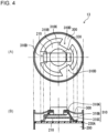
- FIG. 4 illustrates an example of battery 13 having three cut-away portions 310D.
- FIGS. 3(A) and 4(A) are top views of the sealing body of the battery viewed from of electrode body 200, and FIGS. 3(B) and 4(B) are enlarged schematic sectional views of the sealing body magnifying the vicinity of the sealing body.
- two cut-away portions 310D are provided at positions opposite to each other (positions where angles are 0° and 180° in the circumferential direction).
- Internal lead 210 is extended from the connecting portion with electrode body 200 to one cut-away portion, and is then bent to be extended to the other cut-away portion so that internal lead 20 is accommodated between electrode body 200 and external terminal 330. Accordingly, the movement of internal lead 210 in the XY directions can be further suppressed to further enhance the impact resistance.
- FIGS. 2 to 4 illustrate an essential part of the battery including upper insulating plate 230A.
- battery 10 without upper insulating plate 230A illustrated in FIG. 1 can also adopt a structure of cut-away portion 310D similar to FIGS. 2 to 4 .
- a material of gasket 310 is not limited but, for example, polypropylene (PP), polyphenylene sulfide (PPS), polyetheretherketone (PEEK), polyethylene (PE), polybutylene terephthalate (PBT), perfluoroalkoxy alkane (PFA), polytetrafluoroethylene (PTFE), and polyamide (PA) can be used.
- PP polypropylene
- PPS polyphenylene sulfide
- PEEK polyetheretherketone
- PE polyethylene
- PBT polybutylene terephthalate
- PFA perfluoroalkoxy alkane
- PTFE polytetrafluoroethylene
- PA polyamide
- Electrode body 200 having the cylindrical shape is a winding type, and formed by spirally winding positive electrode 201 and negative electrode 202 via separator 203 in between.
- One of positive electrode 201 and negative electrode 202 (positive electrode 201 in an illustrated example) is connected to internal lead 210.
- Internal lead 210 is connected to external terminal 330 typically by welding.
- the other of positive electrode 201 and negative electrode 202 (negative electrode 202 in the illustrated example) is connected to different internal lead 220.
- Internal lead 220 is connected to an inner surface of battery can 100 typically by welding.
- Electrode body 200 is accommodated in battery can 100 together with electrolyte (not illustrated). Normally, to prevent internal short-circuiting, the upper insulating plate and the lower insulating plate are disposed on an upper part and a lower part of electrode body 200, respectively. However, in the battery according to the exemplary embodiment, flange portion 310C of the gasket serves as the upper insulating plate. As illustrated in FIG. 1 , the battery may include only lower insulating plate 230B or both upper insulating plate 230A and lower insulating plate 230B as exemplified in FIG. 2 .
- the positive electrode includes a positive electrode active material.
- Manganese dioxide may be used as the positive electrode active material.
- the positive electrode includes, for example, a positive electrode collector and a positive electrode mixture layer attached to the positive electrode collector.
- the positive electrode mixture layer may contain resin material, such as fluorine resin, as binder in addition to the positive electrode active material.
- the positive electrode mixture layer may further contain conductive material, such as a carbon material, as conductive agent.
- the positive electrode collector is, for example, an expanded metal, a net, or a punching metal made of stainless steel.
- the negative electrode includes a negative electrode active material.
- Metallic lithium or lithium alloy may be used as the negative electrode active material.
- extrusion molding is performed on the metallic lithium or lithium alloy to form a long sheet to be used as the negative electrode.
- the lithium alloy is, for example, alloy of LI-AL, Li-Sn, Li-Ni-Si, or Li-Pb, but Li-Al alloy is preferable.
- Content of metal element other than lithium in the lithium alloy may range preferably from 0.1% by mass to 5% by mass.
- the separator is preferably a fine porous membrane or nonwoven fabric made of resin.
- a material (resin) of the separator is preferably polyolefin, polyamide, polyamideimide, and the like.
- the electrolyte is nonaqueous solvent in which lithium salt is dissolved.
- the nonaqueous solvent is not particularly limited, but propylene carbonate, ethylene carbonate, 1, 2-dimethoxyethane, or ⁇ -butyrolactone can be used.
- As the lithium salt lithium borofluoride, lithium hexafluorophosphate, lithium trifluoromethanesulfonate, lithium bis (fluorosulfonyl) imide, lithium bis (trifluoromethylsulfonyl) imide, and the like may be used.
- a through-hole with a diameter of about 3 mm was formed in the center of the sealing plate with a diameter of 17 mm.
- the rivet to serve as the external terminal was fixed via the insulating gasket and the washer to prepare the sealing body.
- the gasket prepared includes sloped portion 310B extended from the sealing part sealing between the external terminal and the sealing plate and flange portion 310C. Angle ⁇ of 30° was formed between the extending direction of the sloped portion and a normal direction of the sealing plate. An extending length of the sloped portion was a length such that the flange portion contacts the electrode body when the sealing body is overlaid on the opening of the battery can.
- Width W of the flange portion in the radial direction was 3 mm, and outer diameter D of the flange portion was 14 mm.
- one notch (cut-away portion) was formed in the sloped portion and the flange portion.
- Ketjen black of 3.5 parts by mass, which is the conductive agent, polytetrafluoroethylene of 4.5 parts by mass, which is the binder, and pure water of appropriate amount were added to electrolytic manganese dioxide of 92 parts by mass, which is the positive electrode active material, and kneaded to prepare a wet positive electrode mix.
- the wet positive electrode mix was applied to the positive electrode collector made of stainless steel expanded metal to prepare a positive electrode precursor. Then, the positive electrode precursor was dried, rolled by roll press, and cut into predetermined dimensions to complete a positive electrode strip.
- ALi-Al alloy sheet (Al content: 0.3% by mass) was cut into predetermined dimensions to complete a negative electrode strip.
- the positive electrode mixture was partially peeled from a portion of the positive electrode to expose the positive electrode collector.
- a positive electrode tab lead made of stainless steel was welded to the exposed portion of the positive electrode.
- a negative electrode tab lead made of nickel was press attached to a predetermined portion of the negative electrode.
- the positive electrode, the negative electrode, and the separator interposed between the electrodes were spirally wound to configure the electrode body with a cylindrical shape (diameter: 16 mm).
- the polyethylene fine porous membrane was used as the separator.
- PC propylene carbonate
- the electrode body was inserted into a bottomed cylindrical battery can (made of SUS316L).
- the negative electrode tab lead was welded onto an inner bottom of the battery can, and the positive electrode tab lead was welded onto the external terminal fixed on the sealing plate.
- the electrolyte filled inside the battery can, and the sealing body was placed on the opening of the battery can such that the positive electrode tab lead is folded while that the positive electrode tab lead was partially arranged in the cut-away portion of the gasket.
- the sealing plate was laser-welded onto of the battery can in the vicinity of the opening of the battery can.
- the gasket having two notches in the sloped portion and the flange portion was used.
- the other points were set to be the same as Example 1, and twenty hermetically sealed cylindrical lithium batteries having the structure illustrated in FIG. 3 were prepared.
- the batteries were evaluated similarly to Example 1.
- the gasket having three notches in the sloped portion and the flange portion was used.
- the other points were set to be the same as Example 1, and twenty hermetically sealed cylindrical lithium batteries having the structure illustrated in FIG. 4 were prepared.
- the batteries were evaluated similarly to Example 1.
- the gasket having two notches in the sloped portion and the flange portion was used.
- two through-holes (diameter: 1.5 mm) were formed in the flange portion of the gasket at positions forming angles of ⁇ 90° in the circumferential direction with respect to the notches.
- Example 2 The other points were the same as Example 1, and twenty hermetically sealed cylindrical lithium batteries having the structure illustrated in FIG. 3 and the through-holes in the second portion of the gasket were prepared. The batteries were evaluated similarly.
- the gasket provided with a plate part extending from the sealing part sealing between the external terminal and the sealing plate was used.
- An extending length of the plate part was a height such that a tip of the plate part contacts the electrode body when the sealing body is overlaid on the opening of the battery can. The plate part was not notched.
- Example 1 The other points were set to be the same as Example 1, and twenty hermetically sealed cylindrical lithium batteries were prepared. The batteries were evaluated similarly to Example 1.
- Table 1 and Table 2 show evaluation results of the batteries of Examples 1 to 4 and Comparative Example 1 with respect to the internal resistance increase rate due to the drop test.
- Table 1 shows the evaluation results after the drop test performed on initial batteries immediately after preparation.
- Table 2 shows the evaluation results after the drop test performed on the batteries after applying 1000 cycles of thermal impact.
- internal resistance increase rate X1 was equal to or larger than 10% in all ten batteries of Comparative Example 1. Out of which, internal resistance increase rate X1 was equal to or larger than 20% in five batteries. On the other hand, internal resistance increase rate X1 of all ten batteries of Examples 1 to 4 was smaller than 10%. The increase of internal resistance was suppressed even when the drop impact was applied.
- a reason for increased internal resistance due to drop impact is a decreased facing area between the positive electrode and the negative electrode caused by winding deviation of the electrode body due to an impact applied in the axial direction (Z-direction) of the battery.
- lateral deviation of the internal lead due to an impact applied in the radial direction (XY directions) of the battery has reduced the welding area with the internal lead or has broken the connection.
- the winding deviation of the electrode body was suppressed but the lateral deviation of the internal lead was not suppressed. It is assumed that internal resistance increase rate X1 has significantly increased, compared with Examples 1 to 4, due to this reason.
- the through-hole formed in the flange portion of the gasket in Example 4 suppresses internal resistance increase rate X2 to a value less than 10% in all ten batteries even after applying the thermal impact.
- Table 1 Internal resistance increase rate X1 Less than 10% Equal to or larger than 10% and equal to or less than 20% Equal to or larger than 20%
- Example 1 10 0 0 Example 2 10 0 0
- Example 3 10 0 0
- Example 4 10 0 0 Comparative Example 1 0 5 5
- Table 2 Internal resistance increase rate X2 Less than 10% Equal to or larger than 10% and equal to or less than 20% Equal to or larger than 20%
- a hermetically sealed battery according to the present disclosure has good impact resistance and is effectively applicable to a power source of various electronic apparatuses.
Landscapes
- Chemical & Material Sciences (AREA)
- Chemical Kinetics & Catalysis (AREA)
- Electrochemistry (AREA)
- General Chemical & Material Sciences (AREA)
- Engineering & Computer Science (AREA)
- Manufacturing & Machinery (AREA)
- Sealing Battery Cases Or Jackets (AREA)
- Connection Of Batteries Or Terminals (AREA)
Abstract
Description
- The present disclosure relates to a hermetically sealed battery including a battery can, an electrode body accommodated in the battery can, and a sealing plate covering an opening of the battery can.
- As a method of sealing a hermetically sealed battery, PTL 1 discloses a structure that includes a battery case, a sealing plate covering an opening of the battery case, a rivet disposed on the sealing plate and serving as a terminal, and a gasket insulating the sealing plate from the rivet. On a lower side of the sealing plate (side facing an electrode plate group), the gasket is bent in a direction of an electrode plate group to surround a metal washer electrically connected to a current collecting lead of the electrode plate group. This structure suppresses movement of the electrode plate group to prevent upward displacement of the electrode plate typically due to a drop impact.
- PTL 1:
Japanese Patent Laid-Open Publication No. 11-167909 - However, an actual drop direction is not limited to a direction from the electrode plate group toward the sealing plate (a Z-direction), and a drop impact may be applied in a direction (XY direction) perpendicular to the direction from the electrode plate group toward the sealing plate. In PTL 1, when an impact is applied in the XY direction, a connecting part with the current collecting lead moves according to movement of the electrode plate group. In this case, when the current collecting lead is not sufficiently extended, a tension occurs in the current collecting lead. As a result, the washer may be partially or completely disconnected from the current collecting lead, thus causing an electrical connection failure.
- A hermetically sealed battery in accordance with one aspect of the present disclosure includes a battery can having a bottomed cylindrical shape and an opening, an electrode body accommodated in the battery can, a sealing plate covering the opening of the battery can, a rivet disposed on the sealing plate and serving as a terminal, an insulator insulates the sealing plate from the rivet, and an internal lead electrically connected to the rivet. The insulator includes a sealing part sealing between the sealing plate and the rivet and a plate part closer to the electrode body than the sealing part, the plate part being extended in a radial direction of the electrode body. The plate part has a cut-away portion recessed in a periphery of the plate part in the radial direction. The internal lead is partially disposed in the cut-away portion.
- The present disclosure offers a hermetically sealed battery with preferable impact resistance to retain electrical connection between the electrode body and the terminal even when an impact typically caused by dropping is applied.
-
-
FIG. 1 is a schematic sectional view of a hermetically sealed battery in accordance with an exemplary embodiment of the present disclosure. -
FIG. 2 is top view (A) and sectional view (B) of an essential part of a hermetically sealed battery in accordance with another exemplary embodiment of the present disclosure. -
FIG. 3 is top view (A) and sectional view (B) of an essential part of a hermetically sealed battery in accordance with still another exemplary embodiment of the present disclosure. -
FIG. 4 is top view (A) and sectional view (B) of an essential part of a hermetically sealed battery in accordance with a further exemplary embodiment of the present disclosure. - A hermetically sealed battery (hereinafter also simply referred to as a battery) includes a battery can that has a bottomed cylindrical shape and an opening, an electrode body accommodated in the battery can, a sealing plate covering the opening of the battery can, a rivet disposed on the sealing plate and serving as a terminal, an insulator insulating the sealing plate from the rivet, and an internal lead electrically connected to the rivet. The insulator is, for example, a gasket. The insulator may be made of resin material.
- In the following description, a direction of the battery from the electrode body toward the terminal (rivet) is defined as a Z-direction. The Z-direction is referred to as a vertical direction, an axial direction, or a height direction of the battery. A direction perpendicular to the direction (Z-direction) from the electrode body toward the terminal (rivet) is referred to as XY directions. The XY direction includes a radial direction.
- The insulator includes a sealing part sealing between the sealing plate and the rivet and a plate part disposed closer to the electrode body than the sealing part and extended in the radial direction of the electrode body. The plate part restricts movement of the electrode body in the Z-direction. The plate part is extended in the Z-direction to the vicinity of the electrode body. The plate part preferably protrudes in the Z-direction and contacts an insulating plate disposed above the electrode body or directly contacts the electrode body. As a result, the position of the electrode body along the Z-direction is fixed to enhance impact resistance even when a drop impact and the like is applied. In addition, an increase of internal resistance due to winding deviation of the electrode body is suppressed, thus providing a reliable battery.
- The plate part has a cut-away portion recessed in a periphery in the radial direction. The internal lead is partially disposed in the cut-away portion so that the internal lead is extended in the cut-away portion. This configuration restricts movement (or rotation) of the internal lead in the XY directions, and restricts movement (or rotation) of the electrode body connected to the internal lead in the XY directions. Accordingly, the position of the electrode body is fixed in an arbitrary three-dimensional direction, and thus the impact resistance is further enhanced when a drop impact and the like is applied. Furthermore, the increase of internal resistance due to disconnection of the internal lead is suppressed, thus providing a reliable battery.
- The internal lead partially disposed in the cut-away portion restricts a movement (rotation) of the internal lead and the electrode body in the XY directions, hence enhancing the impact resistance. This is particularly effective in that in case of using an electrode body with a small diameter, as a space between the electrode body and the battery can is large, the electrode body easily allow to move in the XY directions due to a drop impact and the like .
- The cut-away portion is formed by, for example, notching a portion of the periphery of the plate part (
FIG. 2(A) ). For example, the internal lead may pass through a clearance in the plate part created by the cut-away portion and folded to be accommodated between the electrode body and the terminal. Accordingly, the internal lead is locked with the cut-away portion of the plate part. This configuration restricts a movement of the internal lead according to the movement of the electrode body. - One cut-away portion or plural cut-away portions may be provided in the periphery of the plate part. The plural cut-away portions in the periphery of the plate part easily restricts the movement of the electrode body.
- The plate part may include a sloped portion in which a point on the sloped portion approaches the electrode body as shifting outward in the radial direction. In this case, the sloped portion serves as a spring capable of reducing an impact. In addition, since a portion of the sloped portion contacting the insulating plate (or electrode body) approaches outside in the radial direction, an aera of the contacting portion increases to securely fix the electrode body against the drop impact and the like. As a result, impact resistance is enhanced and thus reliability is improved.
- Tilt angle θ of the sloped portion in an extending direction with respect to the axial direction of the battery may range, for example, from 20° to 70°.
- The plate part may preferably further include a flange portion bent from the sloped portion and extended outward in the radial direction along an end surface of the electrode body. The flange portion is extended, for example, on a surface of the insulating plate or a flat surface along the end surface of the electrode body to form a flat portion. In this case, a surface of the flange portion contacts a surface of the insulating plate (or electrode body) at a large aera. Accordingly, the electrode body may be reliably fixed against the drop impact and the like to enhance the impact resistance, thus providing a reliable battery.
- The insulating plate is often provided above the electrode body to insulate the electrode body from the battery can and the terminal to prevent internal short-circuiting. However, the plate part including the flange portion may not require the insulating plate separately since the flange portion may serve as the insulating plate.
- The flange portion may press the electrode body in the Z-direction. This configuration fixes the position of the electrode body in the Z-direction. Furthermore, a friction force caused by pressing also suppresses displacement of the electrode body in the XY directions, thus fixing the position thereof in the XY directions. Accordingly, an effect of fixing the position of the electrode body in the arbitrary three-dimensional direction is increased to enhance the impact resistance against the drop impact and the like. As a result, the increase of internal resistance due to winding deviation of the electrode body or disconnection of the internal lead can be suppressed, thus providing a reliable battery.
- In consideration of an expansion of the electrode body in actual use, the flange portion may protrude outward in the radial direction from the electrode body of the battery immediately after manufacturing. In this case, a space exists between the battery can and the electrode body, and thus the electrode body may be easily moved in the XY direction. However, the cut-away portion and the flange portion suppress the movement of the electrode body in the XY directions against the drop impact and the like.
- In the case that the insulating plate is provided, width W of the flange portion in the radial direction may range, for example, from 0.05 times to 0.5 times of the maximum diameter of the electrode body. When width W is 0.05 times or more of the maximum diameter of the electrode body, a displacement of the electrode body can be easily suppressed in the arbitrary three-dimensional direction via the insulating plate. From a view of enhancing a suppression effect of displacement while reducing a volume occupied by the flange portion inside the battery, width W may range preferably from 0.1 times to 0.4 times of the maximum diameter of the electrode body, and more preferably from 0.2 times to 0.3 times. In the case that the maximum diameter of the electrode body is 16 mm, width W may range, for example, from 0.8 mm to 8. 0 mm.
- On the other hand, in the case that the insulating plate is not provided, a sufficiently large contact area between the flange portion and the electrode body is preferably secured in order to suppress the displacement of the electrode body in the arbitrary three-dimensional direction. In this case, width W of the flange portion in the radial direction may range from 0.1 times to 0.7 times of the maximum diameter of the electrode body. From a view of enhancing the suppression effect of positional deviation while reducing the volume occupied by the flange portion inside the battery, width W ranges preferably from 0.2 times to 0.6 times of the maximum diameter of the electrode body, and more preferably from 0.3 times to 0.5 times. In the case that the maximum diameter of the electrode body is 16 mm, width W may range, for example, from 1.6 mm to 11.2 mm.
- Similarly to width W, outer diameter D of the flange portion also depends on a presence of the insulating plate. In the case that the insulating plate is provided, outer diameter D of the flange portion may range, for example, from 0.5 times to 1.1 times of the maximum diameter of the electrode body. In the case that the insulating plate is not provided, outer diameter D may range from 0.7 times to 1.5 times.
- The flange portion may have a through-hole provided therein. The through-hole suppresses warping of the insulator due to aging of the insulator.
- The insulator expands or shrinks due to aging, and may warp. In particular, when the flange portion of the insulator warps, the flange portion is no longer flat and the contact area with the electrode body (or insulating plate) decreases. As a result, the effect of fixing the electrode body against the drop impact and the like may decrease. However, the through-hole expands or shrinks to suppress warping. Accordingly, a high effect of fixing the electrode body in a long duration of use can be maintained to enhance the impact resistance and improve the reliability.
- The opening of the through-hole created in the flange portion preferably has a circular shape. In this case, a diameter of the through-hole may range, for example, from 0.6 mm to 3 mm in the case that the maximum diameter of the electrode body is 16 mm. The diameter of the through-hole may range, for example, from 0.3 times to 0.7 times of width W of a second portion. The through-hole may be created at each of one or more positions along a circumferential direction of the flange portion.
- The hermetically sealed battery in accordance with an exemplary embodiment will be described below with reference to the drawings. However, the exemplary embodiment is not limited thereto. In the drawings, same reference marks are given to components having the same functions.
-
FIG. 1 is a longitudinal sectional view of the hermetically sealed battery. -
Battery 10 includes battery can 100 having a bottomed cylindrical shape,electrode body 200 having a cylindrical shape and accommodated in battery can 100, and sealingplate 300 covering an opening of battery can 100.Sealing plate 300 is fixed to battery can 100 in the vicinity of the opening of battery can 100 typically by laser welding.Sealing plate 300 may be crimped in the vicinity of the opening of battery can 100. - A material of battery can 100 and sealing
plate 300 is not particularly limited, and iron and/or iron alloy (including stainless steel), aluminum, aluminum alloy (alloy containing a slight amount of other metal such as manganese or copper) can be exemplified as the material. -
Sealing plate 300 is fixed to battery can 100 in the vicinity of the opening of battery can 100 to cover the opening.Sealing plate 300 has firstmain surface 300X facing outside the battery can and secondmain surface 300Y opposite to firstmain surface 300X, and has an annular shape with a through-hole provided therein at its center. External terminal 330 (rivet) with a crushed tip portion thereof is fixed in the through-hole at the center of sealingplate 300 via insulating gasket 310 (insulator) andwasher 320.External terminal 330 is connected to an end ofinternal lead 210 led out from a positive electrode or a negative electrode configuring the electrode body. Hereinafter, a component configured with sealingplate 300,gasket 310,washer 320, andexternal terminal 330 may be referred to as a sealing body. However, shapes of sealingplate 300 and the sealing body are not limited thereto. - While not illustrated, a thin portion is provided in sealing
plate 300 or the bottom of battery can 100 between an outer periphery and an inner periphery. When an internal pressure of the battery increases, a pressure is applied in a direction that sealingplate 300 or battery can 100 swells outward. At this point, a tensile stress is intensively applied to the thin portion. When the sealing plate or the battery breaks at the thin portion, an explosion-proof function activates to release the internal pressure. -
Gasket 310 is, for example, made of a resin material, and is formed by insert molding or injection molding together with sealingplate 300.Gasket 310 includes sealingpart 310A that seals between sealingplate 300 andexternal terminal 330, and the plate part that is closer toelectrode body 200 than sealingpart 310A and extended in the radial direction. The plate part includes slopedportion 310B extended outward along the radial direction from sealingpart 310A towardelectrode body 200, andflange portion 310C that is bent and extended outward along the radial direction from slopedportion 310B along the end surface ofelectrode body 200. -
Sloped portion 310B restricts the movement of the electrode body in the Z-direction. This configuration enhances the impact resistance and suppresses an increase of internal resistance due to winding deviation of the electrode body even when the drop impact and the like is applied, thus providing a reliable battery. - In
battery 10 illustrated inFIG. 1 ,flange portion 310C directlycontacts electrode body 200.Flange portion 310C has at least a flat surface facing the electrode body, and the flat surface is extended outward along the radial direction along an outer surface (end surface) ofelectrode body 200 to surface-contact the outer surface of the electrode body. Flange portion 301C preferably presseselectrode body 200. This configuration enhances the effect of fixing the position of the electrode body in the arbitrary three-dimensional direction, and the impact resistance against the drop impact and the like can be improved. As a result, the increase of the internal resistance due to winding deviation of the electrode body or disconnection of internal wiring can be further suppressed to achieve the highly-reliable battery. -
Flange portion 310C may contact the insulating plate (upper insulating plate) provided onelectrode body 200. In this case,flange portion 310C presseselectrode body 200 via the upper insulating plate. Accordingly, the position of the electrode body can be fixed in the arbitrary three-dimensional direction to improve the impact resistance against the drop impact and the like. As a result, the increase of the internal resistance due to winding deviation of the electrode body or disconnection of internal wiring can be further suppressed to achieve the highly-reliable battery. -
FIG. 2 is a schematic view of an essential part ofbattery 11 including upper insulatingplate 230A.FIG. 2(A) is a top view of the sealing body ofbattery 11 viewed fromelectrode body 200.FIG. 2(B) is an enlarged schematic sectional view of a part of the battery in the vicinity of the sealing body. - As illustrated in
FIG. 2 ,gasket 310 is extended while inclining such that a point on the gasket approacheselectrode body 200 as the point shifts outward along the radial direction from sealingpart 310A towardelectrode body 200. A portion of the gasket extended inclining constitutes slopedportion 310B.Gasket 310 is further bend from slopedportion 310B and extended outward in the radial direction along a surface of upper insulatingplate 230A on a gasket side. This portion extending outward in the radial direction along the outer surface (end surface) of the electrode body constitutesflange portion 310C. - A periphery of
gasket 310 is partially notched in slopedportion 310B andflange portion 310C to form cut-away portion 310D.Internal lead 210 is extended in a clearance created by cut-away portion 310D insloped portion 310B andflange portion 310C and is folded to be accommodated betweenelectrode body 200 andexternal terminal 330. Sinceinternal lead 210 is extended to cut-away portion 310D, the displacement ofinternal lead 210 in the XY directions is restricted. Accordingly, the impact resistance is enhanced to suppress the increase of internal pressure due to disconnection of the internal lead. As a result, the highly-reliable battery can be achieved. - Since
internal lead 210 is extended to cut-away portion 310D, longinternal lead 210 can be accommodated. When the drop impact and the like is applied, a force applied to a connected portion ofexternal terminal 330 andinternal lead 210 with respect to the movement ofelectrode body 200 is reduced more in a longer lead wire and thus the impact resistance is enhanced. - Plural cut-away
portions 310D may be provided in the circumferential direction. Plural cut-awayportions 310D provided in the circumferential direction easily restricts the movement of the electrode body in the XY directions. -
FIG. 3 illustrates an example ofbattery 12 having two cut-awayportions 310D.FIG. 4 illustrates an example ofbattery 13 having three cut-awayportions 310D. InFIG. 3 andFIG. 4 , similar toFIG. 2 ,FIGS. 3(A) and4(A) are top views of the sealing body of the battery viewed from ofelectrode body 200, andFIGS. 3(B) and4(B) are enlarged schematic sectional views of the sealing body magnifying the vicinity of the sealing body. - In
battery 12 illustrated inFIG. 3 , two cut-awayportions 310D are provided at positions opposite to each other (positions where angles are 0° and 180° in the circumferential direction).Internal lead 210 is extended from the connecting portion withelectrode body 200 to one cut-away portion, and is then bent to be extended to the other cut-away portion so that internal lead 20 is accommodated betweenelectrode body 200 andexternal terminal 330. Accordingly, the movement ofinternal lead 210 in the XY directions can be further suppressed to further enhance the impact resistance. -
FIGS. 2 to 4 illustrate an essential part of the battery including upper insulatingplate 230A. However, inbattery 10 without upper insulatingplate 230A illustrated inFIG. 1 can also adopt a structure of cut-away portion 310D similar toFIGS. 2 to 4 . - A material of
gasket 310 is not limited but, for example, polypropylene (PP), polyphenylene sulfide (PPS), polyetheretherketone (PEEK), polyethylene (PE), polybutylene terephthalate (PBT), perfluoroalkoxy alkane (PFA), polytetrafluoroethylene (PTFE), and polyamide (PA) can be used. - Next, the structure of the electrode body will be described taking a lithium primary battery as an example.
-
Electrode body 200 having the cylindrical shape is a winding type, and formed by spirally windingpositive electrode 201 and negative electrode 202 viaseparator 203 in between. One ofpositive electrode 201 and negative electrode 202 (positive electrode 201 in an illustrated example) is connected tointernal lead 210.Internal lead 210 is connected toexternal terminal 330 typically by welding. The other ofpositive electrode 201 and negative electrode 202 (negative electrode 202 in the illustrated example) is connected to differentinternal lead 220.Internal lead 220 is connected to an inner surface of battery can 100 typically by welding. -
Electrode body 200 is accommodated in battery can 100 together with electrolyte (not illustrated). Normally, to prevent internal short-circuiting, the upper insulating plate and the lower insulating plate are disposed on an upper part and a lower part ofelectrode body 200, respectively. However, in the battery according to the exemplary embodiment,flange portion 310C of the gasket serves as the upper insulating plate. As illustrated inFIG. 1 , the battery may include only lower insulatingplate 230B or both upper insulatingplate 230A and lower insulatingplate 230B as exemplified inFIG. 2 . - The positive electrode includes a positive electrode active material. Manganese dioxide may be used as the positive electrode active material. The positive electrode includes, for example, a positive electrode collector and a positive electrode mixture layer attached to the positive electrode collector. The positive electrode mixture layer may contain resin material, such as fluorine resin, as binder in addition to the positive electrode active material. The positive electrode mixture layer may further contain conductive material, such as a carbon material, as conductive agent. The positive electrode collector is, for example, an expanded metal, a net, or a punching metal made of stainless steel.
- The negative electrode includes a negative electrode active material. Metallic lithium or lithium alloy may be used as the negative electrode active material. For example, extrusion molding is performed on the metallic lithium or lithium alloy to form a long sheet to be used as the negative electrode. The lithium alloy is, for example, alloy of LI-AL, Li-Sn, Li-Ni-Si, or Li-Pb, but Li-Al alloy is preferable. Content of metal element other than lithium in the lithium alloy may range preferably from 0.1% by mass to 5% by mass.
- The separator is preferably a fine porous membrane or nonwoven fabric made of resin. A material (resin) of the separator is preferably polyolefin, polyamide, polyamideimide, and the like.
- The electrolyte is nonaqueous solvent in which lithium salt is dissolved. The nonaqueous solvent is not particularly limited, but propylene carbonate, ethylene carbonate, 1, 2-dimethoxyethane, or γ-butyrolactone can be used. As the lithium salt, lithium borofluoride, lithium hexafluorophosphate, lithium trifluoromethanesulfonate, lithium bis (fluorosulfonyl) imide, lithium bis (trifluoromethylsulfonyl) imide, and the like may be used.
- The present disclosure will be detailed below with reference to examples and a comparative example. However, the present disclosure is not limited to the following examples.
- A through-hole with a diameter of about 3 mm was formed in the center of the sealing plate with a diameter of 17 mm. In this through-hole, the rivet to serve as the external terminal was fixed via the insulating gasket and the washer to prepare the sealing body. The gasket prepared includes sloped
portion 310B extended from the sealing part sealing between the external terminal and the sealing plate andflange portion 310C. Angle θ of 30° was formed between the extending direction of the sloped portion and a normal direction of the sealing plate. An extending length of the sloped portion was a length such that the flange portion contacts the electrode body when the sealing body is overlaid on the opening of the battery can. Width W of the flange portion in the radial direction was 3 mm, and outer diameter D of the flange portion was 14 mm. In the circumferential direction, one notch (cut-away portion) was formed in the sloped portion and the flange portion. - Ketjen black of 3.5 parts by mass, which is the conductive agent, polytetrafluoroethylene of 4.5 parts by mass, which is the binder, and pure water of appropriate amount were added to electrolytic manganese dioxide of 92 parts by mass, which is the positive electrode active material, and kneaded to prepare a wet positive electrode mix.
- Next, the wet positive electrode mix was applied to the positive electrode collector made of stainless steel expanded metal to prepare a positive electrode precursor. Then, the positive electrode precursor was dried, rolled by roll press, and cut into predetermined dimensions to complete a positive electrode strip.
- ALi-Al alloy sheet (Al content: 0.3% by mass) was cut into predetermined dimensions to complete a negative electrode strip.
- The positive electrode mixture was partially peeled from a portion of the positive electrode to expose the positive electrode collector. A positive electrode tab lead made of stainless steel was welded to the exposed portion of the positive electrode. A negative electrode tab lead made of nickel was press attached to a predetermined portion of the negative electrode. The positive electrode, the negative electrode, and the separator interposed between the electrodes were spirally wound to configure the electrode body with a cylindrical shape (diameter: 16 mm). The polyethylene fine porous membrane was used as the separator.
- Ethylene carbonate (EC), and 1, 2-dimetoxyethane (DME) mixed at a volume ratio of 2:1:2, lithium trifluoromethanesulfonate, as the lithium salt, was dissolved in a nonaqueous solvent of propylene carbonate (PC) at a concentration of 0.5 mol/liter to prepare the electrolyte.
- While a lower insulating plate with a ring shape was disposed on a bottom of the electrode body, the electrode body was inserted into a bottomed cylindrical battery can (made of SUS316L). The negative electrode tab lead was welded onto an inner bottom of the battery can, and the positive electrode tab lead was welded onto the external terminal fixed on the sealing plate. Next, the electrolyte filled inside the battery can, and the sealing body was placed on the opening of the battery can such that the positive electrode tab lead is folded while that the positive electrode tab lead was partially arranged in the cut-away portion of the gasket. Then, the sealing plate was laser-welded onto of the battery can in the vicinity of the opening of the battery can.
- Twenty hermetically sealed cylindrical lithium batteries having the structure illustrated in
FIG. 1 were thus prepared. - Evaluation
- A drop test in accordance with IEC 60086-4 and JIS C 60068-2-31was performed on ten lithium batteries out of the twenty lithium batteries immediately after preparation. Before and after the drop test, an internal resistance was measured to obtain internal resistance increase rate X1 due to the drop test.

- Remaining ten lithium batteries out of the twenty lithium batteries were left at -40°C for 20 minutes and then at 85°C for 20 minutes on the assumption of aging. Considering these temperatures as one cycle, a -40°C and 85°C cycle was repeated 1,000 times.
- The same drop test as the batteries immediately after preparation was performed on the batteries after 1000 cycles. The internal resistance before and after the drop test was measured to obtain internal resistance increase rate X2. However, in the drop test, a height to drop the batteries was changed from 1 m to 1.5 m.
- In the preparation of the sealing body, the gasket having two notches in the sloped portion and the flange portion was used. The other points were set to be the same as Example 1, and twenty hermetically sealed cylindrical lithium batteries having the structure illustrated in
FIG. 3 were prepared. The batteries were evaluated similarly to Example 1. - In the preparation of the sealing body, the gasket having three notches in the sloped portion and the flange portion was used. The other points were set to be the same as Example 1, and twenty hermetically sealed cylindrical lithium batteries having the structure illustrated in
FIG. 4 were prepared. The batteries were evaluated similarly to Example 1. - In the preparation of the sealing body, the gasket having two notches in the sloped portion and the flange portion was used.
- In addition, two through-holes (diameter: 1.5 mm) were formed in the flange portion of the gasket at positions forming angles of ±90° in the circumferential direction with respect to the notches.
- The other points were the same as Example 1, and twenty hermetically sealed cylindrical lithium batteries having the structure illustrated in
FIG. 3 and the through-holes in the second portion of the gasket were prepared. The batteries were evaluated similarly. - In the preparation of the sealing body, the gasket provided with a plate part extending from the sealing part sealing between the external terminal and the sealing plate was used. However, the plate part was extended in parallel with the normal direction (θ = 0°) of the sealing plate, and the flange portion extending outward in the radial direction was not provided. An extending length of the plate part was a height such that a tip of the plate part contacts the electrode body when the sealing body is overlaid on the opening of the battery can. The plate part was not notched.
- The other points were set to be the same as Example 1, and twenty hermetically sealed cylindrical lithium batteries were prepared. The batteries were evaluated similarly to Example 1.
- Table 1 and Table 2 show evaluation results of the batteries of Examples 1 to 4 and Comparative Example 1 with respect to the internal resistance increase rate due to the drop test. Table 1 shows the evaluation results after the drop test performed on initial batteries immediately after preparation. Table 2 shows the evaluation results after the drop test performed on the batteries after applying 1000 cycles of thermal impact.
- As shown in Table 1, with respect to the results after the drop test performed on the batteries immediately after preparation, internal resistance increase rate X1 was equal to or larger than 10% in all ten batteries of Comparative Example 1. Out of which, internal resistance increase rate X1 was equal to or larger than 20% in five batteries. On the other hand, internal resistance increase rate X1 of all ten batteries of Examples 1 to 4 was smaller than 10%. The increase of internal resistance was suppressed even when the drop impact was applied.
- A reason for increased internal resistance due to drop impact is a decreased facing area between the positive electrode and the negative electrode caused by winding deviation of the electrode body due to an impact applied in the axial direction (Z-direction) of the battery. In addition, lateral deviation of the internal lead due to an impact applied in the radial direction (XY directions) of the battery has reduced the welding area with the internal lead or has broken the connection. In the batteries of Comparative Example 1, the winding deviation of the electrode body was suppressed but the lateral deviation of the internal lead was not suppressed. It is assumed that internal resistance increase rate X1 has significantly increased, compared with Examples 1 to 4, due to this reason.
- On the other hand, as shown in Table 2, the drop test was performed on the batteries after applying the thermal impact. As a result, in Examples 1 to 3, internal resistance increase rate X2 was equal to or larger than 10% and equal to or smaller than 20% in one out of ten batteries. An assumed reason is that the flange portion of the gasket has warped due to degradation of resin of the gasket by the thermal impact, and the effect of fixing in the XY directions and the Z-direction has decreased.
- The through-hole formed in the flange portion of the gasket in Example 4 suppresses internal resistance increase rate X2 to a value less than 10% in all ten batteries even after applying the thermal impact.
Table 1 Internal resistance increase rate X1 Less than 10% Equal to or larger than 10% and equal to or less than 20% Equal to or larger than 20% Example 1 10 0 0 Example 2 10 0 0 Example 3 10 0 0 Example 4 10 0 0 Comparative Example 1 0 5 5 Table 2 Internal resistance increase rate X2 Less than 10% Equal to or larger than 10% and equal to or less than 20% Equal to or larger than 20% Example 1 9 1 0 Example 2 9 1 0 Example 3 9 1 0 Example 4 10 0 0 Comparative Example 1 0 2 8 - A hermetically sealed battery according to the present disclosure has good impact resistance and is effectively applicable to a power source of various electronic apparatuses.
-
- 10, 11, 12
- battery
- 100
- battery can
- 200
- electrode body
- 201
- positive electrode
- 202
- negative electrode
- 203
- separator
- 210, 220
- internal lead
- 230A
- upper insulating plate
- 230B
- lower insulating plate
- 300
- sealing plate
- 300X
- first main surface
- 300Y
- second main surface
- 310
- gasket
- 310A
- sealing part
- 310B
- sloped portion
- 310C
- flange portion
- 310D
- cut-away portion
- 320
- washer
- 330
- external terminal
Claims (4)
- A hermetically sealed battery comprising:a battery can having a bottomed cylindrical shape and an opening;an electrode body accommodated in the battery can;a sealing plate covering the opening of the battery can;a rivet disposed on the sealing plate and serving as a terminal;an insulator insulates the sealing plate from the rivet; andan internal lead electrically connected to the rivet, whereinthe insulator includes:a sealing part sealing between the sealing plate and the rivet; anda plate part closer to the electrode body than the sealing part, the plate part being extended in a radial direction of the electrode body,the plate part has a cut-away portion recessed in a periphery of the plate part in the radial direction, andthe internal lead is partially disposed in the cut-away portion.
- The hermetically sealed battery according to claim 1, wherein the plate part includes a sloped portion, a point on the sloped portion approaching the electrode body as the point shifting outward in the radial direction.
- The hermetically sealed battery according to claim 2, wherein the plate part further includes a flange portion bent from the sloped portion and extended outward in the radial direction.
- The hermetically sealed battery according to claim 3, wherein the flange portion has a through-hole provided therein.
Applications Claiming Priority (2)
| Application Number | Priority Date | Filing Date | Title |
|---|---|---|---|
| JP2020086230 | 2020-05-15 | ||
| PCT/JP2021/015960 WO2021230014A1 (en) | 2020-05-15 | 2021-04-20 | Hermetically sealed battery |
Publications (3)
| Publication Number | Publication Date |
|---|---|
| EP4152494A1 true EP4152494A1 (en) | 2023-03-22 |
| EP4152494A4 EP4152494A4 (en) | 2024-01-03 |
| EP4152494B1 EP4152494B1 (en) | 2024-09-18 |
Family
ID=78525618
Family Applications (1)
| Application Number | Title | Priority Date | Filing Date |
|---|---|---|---|
| EP21802912.2A Active EP4152494B1 (en) | 2020-05-15 | 2021-04-20 | Hermetically sealed battery |
Country Status (5)
| Country | Link |
|---|---|
| US (1) | US12431566B2 (en) |
| EP (1) | EP4152494B1 (en) |
| JP (1) | JP7398719B2 (en) |
| CN (1) | CN115516706B (en) |
| WO (1) | WO2021230014A1 (en) |
Families Citing this family (1)
| Publication number | Priority date | Publication date | Assignee | Title |
|---|---|---|---|---|
| KR102525388B1 (en) * | 2021-06-30 | 2023-04-26 | 삼성에스디아이 주식회사 | Secondary battery |
Family Cites Families (25)
| Publication number | Priority date | Publication date | Assignee | Title |
|---|---|---|---|---|
| JPS57204655U (en) * | 1981-06-24 | 1982-12-27 | ||
| KR100405873B1 (en) * | 1995-07-28 | 2004-03-30 | 산요덴키가부시키가이샤 | Laser Sealed Battery |
| JPH10340709A (en) * | 1997-06-06 | 1998-12-22 | N Ii C Mori Energ Kk | Prismatic battery |
| JPH1131487A (en) * | 1997-07-09 | 1999-02-02 | Matsushita Electric Ind Co Ltd | Cylindrical sealed battery and its manufacturing method |
| JPH11167909A (en) | 1997-12-03 | 1999-06-22 | Matsushita Electric Ind Co Ltd | Explosion-proof valve device for non-aqueous electrolyte batteries |
| JP4479013B2 (en) * | 1998-02-13 | 2010-06-09 | 株式会社ジーエス・ユアサコーポレーション | Cylindrical battery |
| JP2000090908A (en) * | 1998-09-16 | 2000-03-31 | Furukawa Battery Co Ltd:The | Sealed storage battery |
| JP3574772B2 (en) | 1999-12-28 | 2004-10-06 | Necトーキン株式会社 | Cylindrical battery and method of manufacturing the same |
| CN100364149C (en) * | 2001-10-19 | 2008-01-23 | 松下电器产业株式会社 | secondary battery |
| US6828061B2 (en) * | 2001-10-26 | 2004-12-07 | Eveready Battery Company, Inc. | Electrochemical cell with reinforced separator |
| JP4338410B2 (en) * | 2003-01-31 | 2009-10-07 | 三洋電機株式会社 | Battery with spiral electrode group |
| FR2875056B1 (en) * | 2004-09-07 | 2007-03-30 | Accumulateurs Fixes | ACCUMULATOR HAVING TWO CURRENT OUTPUT TERMINALS ON A WALL OF ITS CONTAINER |
| JP2006252890A (en) * | 2005-03-09 | 2006-09-21 | Sanyo Electric Co Ltd | Cylinder-shaped secondary battery and manufacturing method of the same |
| JP5158832B2 (en) | 2006-01-19 | 2013-03-06 | 日立マクセルエナジー株式会社 | Sealed battery |
| JP5322511B2 (en) * | 2008-06-25 | 2013-10-23 | パナソニック株式会社 | Cylindrical sealed battery |
| JP5365855B2 (en) * | 2009-06-04 | 2013-12-11 | トヨタ自動車株式会社 | Sealed secondary battery |
| JP5679181B2 (en) * | 2010-02-22 | 2015-03-04 | Fdkエナジー株式会社 | Gasket for cylindrical battery, cylindrical battery |
| JP2012134108A (en) * | 2010-12-24 | 2012-07-12 | Fdk Twicell Co Ltd | Battery |
| KR101265213B1 (en) * | 2011-06-30 | 2013-05-27 | 로베르트 보쉬 게엠베하 | Rechargeable battery with sealing structure |
| JP2016091670A (en) * | 2014-10-31 | 2016-05-23 | 日立オートモティブシステムズ株式会社 | Cylindrical secondary battery |
| CN107534122B (en) * | 2015-04-27 | 2020-09-29 | 三洋电机株式会社 | Cylindrical battery, current collecting member therefor, and method of manufacturing the same |
| JP6745098B2 (en) * | 2015-09-30 | 2020-08-26 | マクセルホールディングス株式会社 | Sealed battery |
| JP6593659B2 (en) * | 2015-11-13 | 2019-10-23 | パナソニックIpマネジメント株式会社 | Nonaqueous electrolyte battery and nonaqueous electrolyte battery member |
| JP6986346B2 (en) * | 2016-12-19 | 2021-12-22 | Fdk株式会社 | Cylindrical alkaline battery |
| CN111937186B (en) * | 2018-04-06 | 2024-01-02 | 松下知识产权经营株式会社 | Batteries and battery modules |
-
2021
- 2021-04-20 WO PCT/JP2021/015960 patent/WO2021230014A1/en not_active Ceased
- 2021-04-20 CN CN202180033609.7A patent/CN115516706B/en active Active
- 2021-04-20 JP JP2022521790A patent/JP7398719B2/en active Active
- 2021-04-20 EP EP21802912.2A patent/EP4152494B1/en active Active
- 2021-04-20 US US17/924,002 patent/US12431566B2/en active Active
Also Published As
| Publication number | Publication date |
|---|---|
| CN115516706B (en) | 2024-07-26 |
| US20230178831A1 (en) | 2023-06-08 |
| EP4152494B1 (en) | 2024-09-18 |
| US12431566B2 (en) | 2025-09-30 |
| EP4152494A4 (en) | 2024-01-03 |
| JP7398719B2 (en) | 2023-12-15 |
| WO2021230014A1 (en) | 2021-11-18 |
| JPWO2021230014A1 (en) | 2021-11-18 |
| CN115516706A (en) | 2022-12-23 |
Similar Documents
| Publication | Publication Date | Title |
|---|---|---|
| CN111937186B (en) | Batteries and battery modules | |
| US11699834B2 (en) | Sealed battery | |
| KR101084221B1 (en) | Secondary battery | |
| US12308446B2 (en) | Battery | |
| US20110223472A1 (en) | Cylindrical battery cell with non-aqueous electrolyte | |
| CN116895820A (en) | Cylindrical secondary battery | |
| US20250158243A1 (en) | Battery and current collector | |
| EP4300645A1 (en) | Cylindrical battery and manufacturing method for same | |
| US20240039096A1 (en) | Gasket and cylindrical battery | |
| EP4250440A1 (en) | Cylindrical battery | |
| EP4152494B1 (en) | Hermetically sealed battery | |
| US20240387966A1 (en) | Cylindrical battery | |
| US20220407157A1 (en) | Sealed battery | |
| US12272831B2 (en) | Fastening structure | |
| JP5252691B2 (en) | Cylindrical non-aqueous electrolyte primary battery and manufacturing method thereof | |
| US20250192294A1 (en) | Cylindrical battery | |
| WO2020137777A1 (en) | Battery | |
| EP4239764A1 (en) | Cylindrical battery | |
| EP4528893A1 (en) | Cylindrical battery | |
| EP4632884A1 (en) | Cylindrical battery | |
| US20250055159A1 (en) | Cylindrical battery | |
| US20250192293A1 (en) | Cylindrical battery | |
| EP4657645A1 (en) | Secondary battery | |
| JP6413976B2 (en) | battery | |
| JP6529881B2 (en) | Power storage device |
Legal Events
| Date | Code | Title | Description |
|---|---|---|---|
| STAA | Information on the status of an ep patent application or granted ep patent |
Free format text: STATUS: THE INTERNATIONAL PUBLICATION HAS BEEN MADE |
|
| PUAI | Public reference made under article 153(3) epc to a published international application that has entered the european phase |
Free format text: ORIGINAL CODE: 0009012 |
|
| STAA | Information on the status of an ep patent application or granted ep patent |
Free format text: STATUS: REQUEST FOR EXAMINATION WAS MADE |
|
| 17P | Request for examination filed |
Effective date: 20221031 |
|
| AK | Designated contracting states |
Kind code of ref document: A1 Designated state(s): AL AT BE BG CH CY CZ DE DK EE ES FI FR GB GR HR HU IE IS IT LI LT LU LV MC MK MT NL NO PL PT RO RS SE SI SK SM TR |
|
| DAV | Request for validation of the european patent (deleted) | ||
| DAX | Request for extension of the european patent (deleted) | ||
| A4 | Supplementary search report drawn up and despatched |
Effective date: 20231205 |
|
| RIC1 | Information provided on ipc code assigned before grant |
Ipc: H01M 50/179 20210101ALI20231129BHEP Ipc: H01M 50/107 20210101ALI20231129BHEP Ipc: H01M 50/559 20210101ALI20231129BHEP Ipc: H01M 50/553 20210101ALI20231129BHEP Ipc: H01M 50/531 20210101ALI20231129BHEP Ipc: H01M 50/528 20210101ALI20231129BHEP Ipc: H01M 50/188 20210101ALI20231129BHEP Ipc: H01M 50/186 20210101ALI20231129BHEP Ipc: H01M 50/176 20210101ALI20231129BHEP Ipc: H01M 50/171 20210101ALI20231129BHEP Ipc: H01M 50/169 20210101ALI20231129BHEP Ipc: H01M 50/152 20210101ALI20231129BHEP Ipc: H01M 50/593 20210101ALI20231129BHEP Ipc: H01M 50/586 20210101ALI20231129BHEP Ipc: H01M 50/567 20210101ALI20231129BHEP Ipc: H01M 50/533 20210101ALI20231129BHEP Ipc: H01M 50/184 20210101AFI20231129BHEP |
|
| GRAP | Despatch of communication of intention to grant a patent |
Free format text: ORIGINAL CODE: EPIDOSNIGR1 |
|
| STAA | Information on the status of an ep patent application or granted ep patent |
Free format text: STATUS: GRANT OF PATENT IS INTENDED |
|
| INTG | Intention to grant announced |
Effective date: 20240426 |
|
| GRAS | Grant fee paid |
Free format text: ORIGINAL CODE: EPIDOSNIGR3 |
|
| GRAA | (expected) grant |
Free format text: ORIGINAL CODE: 0009210 |
|
| STAA | Information on the status of an ep patent application or granted ep patent |
Free format text: STATUS: THE PATENT HAS BEEN GRANTED |
|
| AK | Designated contracting states |
Kind code of ref document: B1 Designated state(s): AL AT BE BG CH CY CZ DE DK EE ES FI FR GB GR HR HU IE IS IT LI LT LU LV MC MK MT NL NO PL PT RO RS SE SI SK SM TR |
|
| REG | Reference to a national code |
Ref country code: GB Ref legal event code: FG4D |
|
| REG | Reference to a national code |
Ref country code: CH Ref legal event code: EP |
|
| REG | Reference to a national code |
Ref country code: IE Ref legal event code: FG4D |
|
| REG | Reference to a national code |
Ref country code: DE Ref legal event code: R096 Ref document number: 602021019055 Country of ref document: DE |
|
| REG | Reference to a national code |
Ref country code: LT Ref legal event code: MG9D |
|
| PG25 | Lapsed in a contracting state [announced via postgrant information from national office to epo] |
Ref country code: NO Free format text: LAPSE BECAUSE OF FAILURE TO SUBMIT A TRANSLATION OF THE DESCRIPTION OR TO PAY THE FEE WITHIN THE PRESCRIBED TIME-LIMIT Effective date: 20241218 |
|
| PG25 | Lapsed in a contracting state [announced via postgrant information from national office to epo] |
Ref country code: GR Free format text: LAPSE BECAUSE OF FAILURE TO SUBMIT A TRANSLATION OF THE DESCRIPTION OR TO PAY THE FEE WITHIN THE PRESCRIBED TIME-LIMIT Effective date: 20241219 Ref country code: FI Free format text: LAPSE BECAUSE OF FAILURE TO SUBMIT A TRANSLATION OF THE DESCRIPTION OR TO PAY THE FEE WITHIN THE PRESCRIBED TIME-LIMIT Effective date: 20240918 |
|
| PG25 | Lapsed in a contracting state [announced via postgrant information from national office to epo] |
Ref country code: BG Free format text: LAPSE BECAUSE OF FAILURE TO SUBMIT A TRANSLATION OF THE DESCRIPTION OR TO PAY THE FEE WITHIN THE PRESCRIBED TIME-LIMIT Effective date: 20240918 |
|
| PG25 | Lapsed in a contracting state [announced via postgrant information from national office to epo] |
Ref country code: LV Free format text: LAPSE BECAUSE OF FAILURE TO SUBMIT A TRANSLATION OF THE DESCRIPTION OR TO PAY THE FEE WITHIN THE PRESCRIBED TIME-LIMIT Effective date: 20240918 |
|
| PG25 | Lapsed in a contracting state [announced via postgrant information from national office to epo] |
Ref country code: HR Free format text: LAPSE BECAUSE OF FAILURE TO SUBMIT A TRANSLATION OF THE DESCRIPTION OR TO PAY THE FEE WITHIN THE PRESCRIBED TIME-LIMIT Effective date: 20240918 |
|
| REG | Reference to a national code |
Ref country code: NL Ref legal event code: MP Effective date: 20240918 |
|
| PG25 | Lapsed in a contracting state [announced via postgrant information from national office to epo] |
Ref country code: RS Free format text: LAPSE BECAUSE OF FAILURE TO SUBMIT A TRANSLATION OF THE DESCRIPTION OR TO PAY THE FEE WITHIN THE PRESCRIBED TIME-LIMIT Effective date: 20241218 |
|
| PG25 | Lapsed in a contracting state [announced via postgrant information from national office to epo] |
Ref country code: RS Free format text: LAPSE BECAUSE OF FAILURE TO SUBMIT A TRANSLATION OF THE DESCRIPTION OR TO PAY THE FEE WITHIN THE PRESCRIBED TIME-LIMIT Effective date: 20241218 Ref country code: NO Free format text: LAPSE BECAUSE OF FAILURE TO SUBMIT A TRANSLATION OF THE DESCRIPTION OR TO PAY THE FEE WITHIN THE PRESCRIBED TIME-LIMIT Effective date: 20241218 Ref country code: LV Free format text: LAPSE BECAUSE OF FAILURE TO SUBMIT A TRANSLATION OF THE DESCRIPTION OR TO PAY THE FEE WITHIN THE PRESCRIBED TIME-LIMIT Effective date: 20240918 Ref country code: HR Free format text: LAPSE BECAUSE OF FAILURE TO SUBMIT A TRANSLATION OF THE DESCRIPTION OR TO PAY THE FEE WITHIN THE PRESCRIBED TIME-LIMIT Effective date: 20240918 Ref country code: GR Free format text: LAPSE BECAUSE OF FAILURE TO SUBMIT A TRANSLATION OF THE DESCRIPTION OR TO PAY THE FEE WITHIN THE PRESCRIBED TIME-LIMIT Effective date: 20241219 Ref country code: FI Free format text: LAPSE BECAUSE OF FAILURE TO SUBMIT A TRANSLATION OF THE DESCRIPTION OR TO PAY THE FEE WITHIN THE PRESCRIBED TIME-LIMIT Effective date: 20240918 Ref country code: BG Free format text: LAPSE BECAUSE OF FAILURE TO SUBMIT A TRANSLATION OF THE DESCRIPTION OR TO PAY THE FEE WITHIN THE PRESCRIBED TIME-LIMIT Effective date: 20240918 |
|
| REG | Reference to a national code |
Ref country code: AT Ref legal event code: MK05 Ref document number: 1725473 Country of ref document: AT Kind code of ref document: T Effective date: 20240918 |
|
| PG25 | Lapsed in a contracting state [announced via postgrant information from national office to epo] |
Ref country code: NL Free format text: LAPSE BECAUSE OF FAILURE TO SUBMIT A TRANSLATION OF THE DESCRIPTION OR TO PAY THE FEE WITHIN THE PRESCRIBED TIME-LIMIT Effective date: 20240918 |
|
| PG25 | Lapsed in a contracting state [announced via postgrant information from national office to epo] |
Ref country code: IS Free format text: LAPSE BECAUSE OF FAILURE TO SUBMIT A TRANSLATION OF THE DESCRIPTION OR TO PAY THE FEE WITHIN THE PRESCRIBED TIME-LIMIT Effective date: 20250118 Ref country code: PT Free format text: LAPSE BECAUSE OF FAILURE TO SUBMIT A TRANSLATION OF THE DESCRIPTION OR TO PAY THE FEE WITHIN THE PRESCRIBED TIME-LIMIT Effective date: 20250120 |
|
| PG25 | Lapsed in a contracting state [announced via postgrant information from national office to epo] |
Ref country code: RO Free format text: LAPSE BECAUSE OF FAILURE TO SUBMIT A TRANSLATION OF THE DESCRIPTION OR TO PAY THE FEE WITHIN THE PRESCRIBED TIME-LIMIT Effective date: 20240918 Ref country code: SM Free format text: LAPSE BECAUSE OF FAILURE TO SUBMIT A TRANSLATION OF THE DESCRIPTION OR TO PAY THE FEE WITHIN THE PRESCRIBED TIME-LIMIT Effective date: 20240918 |
|
| PG25 | Lapsed in a contracting state [announced via postgrant information from national office to epo] |
Ref country code: ES Free format text: LAPSE BECAUSE OF FAILURE TO SUBMIT A TRANSLATION OF THE DESCRIPTION OR TO PAY THE FEE WITHIN THE PRESCRIBED TIME-LIMIT Effective date: 20240918 |
|
| PG25 | Lapsed in a contracting state [announced via postgrant information from national office to epo] |
Ref country code: AT Free format text: LAPSE BECAUSE OF FAILURE TO SUBMIT A TRANSLATION OF THE DESCRIPTION OR TO PAY THE FEE WITHIN THE PRESCRIBED TIME-LIMIT Effective date: 20240918 Ref country code: EE Free format text: LAPSE BECAUSE OF FAILURE TO SUBMIT A TRANSLATION OF THE DESCRIPTION OR TO PAY THE FEE WITHIN THE PRESCRIBED TIME-LIMIT Effective date: 20240918 |
|
| PG25 | Lapsed in a contracting state [announced via postgrant information from national office to epo] |
Ref country code: CZ Free format text: LAPSE BECAUSE OF FAILURE TO SUBMIT A TRANSLATION OF THE DESCRIPTION OR TO PAY THE FEE WITHIN THE PRESCRIBED TIME-LIMIT Effective date: 20240918 Ref country code: PL Free format text: LAPSE BECAUSE OF FAILURE TO SUBMIT A TRANSLATION OF THE DESCRIPTION OR TO PAY THE FEE WITHIN THE PRESCRIBED TIME-LIMIT Effective date: 20240918 |
|
| PG25 | Lapsed in a contracting state [announced via postgrant information from national office to epo] |
Ref country code: SK Free format text: LAPSE BECAUSE OF FAILURE TO SUBMIT A TRANSLATION OF THE DESCRIPTION OR TO PAY THE FEE WITHIN THE PRESCRIBED TIME-LIMIT Effective date: 20240918 Ref country code: IT Free format text: LAPSE BECAUSE OF FAILURE TO SUBMIT A TRANSLATION OF THE DESCRIPTION OR TO PAY THE FEE WITHIN THE PRESCRIBED TIME-LIMIT Effective date: 20240918 |
|
| REG | Reference to a national code |
Ref country code: DE Ref legal event code: R097 Ref document number: 602021019055 Country of ref document: DE |
|
| PGFP | Annual fee paid to national office [announced via postgrant information from national office to epo] |
Ref country code: DE Payment date: 20250422 Year of fee payment: 5 |
|
| PG25 | Lapsed in a contracting state [announced via postgrant information from national office to epo] |
Ref country code: DK Free format text: LAPSE BECAUSE OF FAILURE TO SUBMIT A TRANSLATION OF THE DESCRIPTION OR TO PAY THE FEE WITHIN THE PRESCRIBED TIME-LIMIT Effective date: 20240918 |
|
| PGFP | Annual fee paid to national office [announced via postgrant information from national office to epo] |
Ref country code: GB Payment date: 20250423 Year of fee payment: 5 |
|
| PGFP | Annual fee paid to national office [announced via postgrant information from national office to epo] |
Ref country code: FR Payment date: 20250425 Year of fee payment: 5 |
|
| PLBE | No opposition filed within time limit |
Free format text: ORIGINAL CODE: 0009261 |
|
| STAA | Information on the status of an ep patent application or granted ep patent |
Free format text: STATUS: NO OPPOSITION FILED WITHIN TIME LIMIT |
|
| 26N | No opposition filed |
Effective date: 20250619 |
|
| PG25 | Lapsed in a contracting state [announced via postgrant information from national office to epo] |
Ref country code: SE Free format text: LAPSE BECAUSE OF FAILURE TO SUBMIT A TRANSLATION OF THE DESCRIPTION OR TO PAY THE FEE WITHIN THE PRESCRIBED TIME-LIMIT Effective date: 20240918 |
|
| REG | Reference to a national code |
Ref country code: CH Ref legal event code: H13 Free format text: ST27 STATUS EVENT CODE: U-0-0-H10-H13 (AS PROVIDED BY THE NATIONAL OFFICE) Effective date: 20251125 |
|
| PG25 | Lapsed in a contracting state [announced via postgrant information from national office to epo] |
Ref country code: LU Free format text: LAPSE BECAUSE OF NON-PAYMENT OF DUE FEES Effective date: 20250420 |
|
| PG25 | Lapsed in a contracting state [announced via postgrant information from national office to epo] |
Ref country code: MC Free format text: LAPSE BECAUSE OF FAILURE TO SUBMIT A TRANSLATION OF THE DESCRIPTION OR TO PAY THE FEE WITHIN THE PRESCRIBED TIME-LIMIT Effective date: 20240918 |
|
| REG | Reference to a national code |
Ref country code: BE Ref legal event code: MM Effective date: 20250430 |
|
| PG25 | Lapsed in a contracting state [announced via postgrant information from national office to epo] |
Ref country code: BE Free format text: LAPSE BECAUSE OF NON-PAYMENT OF DUE FEES Effective date: 20250430 |
|
| PG25 | Lapsed in a contracting state [announced via postgrant information from national office to epo] |
Ref country code: CH Free format text: LAPSE BECAUSE OF NON-PAYMENT OF DUE FEES Effective date: 20250430 |
|
| PG25 | Lapsed in a contracting state [announced via postgrant information from national office to epo] |
Ref country code: IE Free format text: LAPSE BECAUSE OF NON-PAYMENT OF DUE FEES Effective date: 20250420 |