EP4152030B1 - Gradient coil assembly for a magnetic resonance imaging device and magnetic resonance imaging device - Google Patents
Gradient coil assembly for a magnetic resonance imaging device and magnetic resonance imaging device Download PDFInfo
- Publication number
- EP4152030B1 EP4152030B1 EP21197316.9A EP21197316A EP4152030B1 EP 4152030 B1 EP4152030 B1 EP 4152030B1 EP 21197316 A EP21197316 A EP 21197316A EP 4152030 B1 EP4152030 B1 EP 4152030B1
- Authority
- EP
- European Patent Office
- Prior art keywords
- openings
- magnetic resonance
- imaging device
- resonance imaging
- gradient
- Prior art date
- Legal status (The legal status is an assumption and is not a legal conclusion. Google has not performed a legal analysis and makes no representation as to the accuracy of the status listed.)
- Active
Links
Images

Classifications
-
- G—PHYSICS
- G01—MEASURING; TESTING
- G01R—MEASURING ELECTRIC VARIABLES; MEASURING MAGNETIC VARIABLES
- G01R33/00—Arrangements or instruments for measuring magnetic variables
- G01R33/20—Arrangements or instruments for measuring magnetic variables involving magnetic resonance
- G01R33/28—Details of apparatus provided for in groups G01R33/44 - G01R33/64
- G01R33/38—Systems for generation, homogenisation or stabilisation of the main or gradient magnetic field
- G01R33/385—Systems for generation, homogenisation or stabilisation of the main or gradient magnetic field using gradient magnetic field coils
-
- A—HUMAN NECESSITIES
- A61—MEDICAL OR VETERINARY SCIENCE; HYGIENE
- A61B—DIAGNOSIS; SURGERY; IDENTIFICATION
- A61B5/00—Measuring for diagnostic purposes; Identification of persons
- A61B5/0033—Features or image-related aspects of imaging apparatus, e.g. for MRI, optical tomography or impedance tomography apparatus; Arrangements of imaging apparatus in a room
- A61B5/0035—Features or image-related aspects of imaging apparatus, e.g. for MRI, optical tomography or impedance tomography apparatus; Arrangements of imaging apparatus in a room adapted for acquisition of images from more than one imaging mode, e.g. combining MRI and optical tomography
-
- A—HUMAN NECESSITIES
- A61—MEDICAL OR VETERINARY SCIENCE; HYGIENE
- A61B—DIAGNOSIS; SURGERY; IDENTIFICATION
- A61B5/00—Measuring for diagnostic purposes; Identification of persons
- A61B5/05—Detecting, measuring or recording for diagnosis by means of electric currents or magnetic fields; Measuring using microwaves or radio waves
- A61B5/055—Detecting, measuring or recording for diagnosis by means of electric currents or magnetic fields; Measuring using microwaves or radio waves involving electronic [EMR] or nuclear [NMR] magnetic resonance, e.g. magnetic resonance imaging
-
- A—HUMAN NECESSITIES
- A61—MEDICAL OR VETERINARY SCIENCE; HYGIENE
- A61B—DIAGNOSIS; SURGERY; IDENTIFICATION
- A61B5/00—Measuring for diagnostic purposes; Identification of persons
- A61B5/70—Means for positioning the patient in relation to the detecting, measuring or recording means
- A61B5/704—Tables
-
- A—HUMAN NECESSITIES
- A61—MEDICAL OR VETERINARY SCIENCE; HYGIENE
- A61B—DIAGNOSIS; SURGERY; IDENTIFICATION
- A61B6/00—Apparatus or devices for radiation diagnosis; Apparatus or devices for radiation diagnosis combined with radiation therapy equipment
- A61B6/02—Arrangements for diagnosis sequentially in different planes; Stereoscopic radiation diagnosis
- A61B6/03—Computed tomography [CT]
- A61B6/032—Transmission computed tomography [CT]
-
- A—HUMAN NECESSITIES
- A61—MEDICAL OR VETERINARY SCIENCE; HYGIENE
- A61B—DIAGNOSIS; SURGERY; IDENTIFICATION
- A61B6/00—Apparatus or devices for radiation diagnosis; Apparatus or devices for radiation diagnosis combined with radiation therapy equipment
- A61B6/44—Constructional features of apparatus for radiation diagnosis
- A61B6/4417—Constructional features of apparatus for radiation diagnosis related to combined acquisition of different diagnostic modalities
-
- G—PHYSICS
- G01—MEASURING; TESTING
- G01R—MEASURING ELECTRIC VARIABLES; MEASURING MAGNETIC VARIABLES
- G01R33/00—Arrangements or instruments for measuring magnetic variables
- G01R33/20—Arrangements or instruments for measuring magnetic variables involving magnetic resonance
- G01R33/44—Arrangements or instruments for measuring magnetic variables involving magnetic resonance using nuclear magnetic resonance [NMR]
- G01R33/48—NMR imaging systems
- G01R33/4808—Multimodal MR, e.g. MR combined with positron emission tomography [PET], MR combined with ultrasound or MR combined with computed tomography [CT]
-
- G—PHYSICS
- G01—MEASURING; TESTING
- G01R—MEASURING ELECTRIC VARIABLES; MEASURING MAGNETIC VARIABLES
- G01R33/00—Arrangements or instruments for measuring magnetic variables
- G01R33/20—Arrangements or instruments for measuring magnetic variables involving magnetic resonance
- G01R33/44—Arrangements or instruments for measuring magnetic variables involving magnetic resonance using nuclear magnetic resonance [NMR]
- G01R33/48—NMR imaging systems
- G01R33/4808—Multimodal MR, e.g. MR combined with positron emission tomography [PET], MR combined with ultrasound or MR combined with computed tomography [CT]
- G01R33/4812—MR combined with X-ray or computed tomography [CT]
-
- A—HUMAN NECESSITIES
- A61—MEDICAL OR VETERINARY SCIENCE; HYGIENE
- A61B—DIAGNOSIS; SURGERY; IDENTIFICATION
- A61B2562/00—Details of sensors; Constructional details of sensor housings or probes; Accessories for sensors
- A61B2562/18—Shielding or protection of sensors from environmental influences, e.g. protection from mechanical damage
- A61B2562/182—Electrical shielding, e.g. using a Faraday cage
-
- A—HUMAN NECESSITIES
- A61—MEDICAL OR VETERINARY SCIENCE; HYGIENE
- A61B—DIAGNOSIS; SURGERY; IDENTIFICATION
- A61B6/00—Apparatus or devices for radiation diagnosis; Apparatus or devices for radiation diagnosis combined with radiation therapy equipment
- A61B6/02—Arrangements for diagnosis sequentially in different planes; Stereoscopic radiation diagnosis
- A61B6/03—Computed tomography [CT]
- A61B6/037—Emission tomography
-
- A—HUMAN NECESSITIES
- A61—MEDICAL OR VETERINARY SCIENCE; HYGIENE
- A61B—DIAGNOSIS; SURGERY; IDENTIFICATION
- A61B6/00—Apparatus or devices for radiation diagnosis; Apparatus or devices for radiation diagnosis combined with radiation therapy equipment
- A61B6/40—Arrangements for generating radiation specially adapted for radiation diagnosis
- A61B6/4064—Arrangements for generating radiation specially adapted for radiation diagnosis specially adapted for producing a particular type of beam
- A61B6/4092—Arrangements for generating radiation specially adapted for radiation diagnosis specially adapted for producing a particular type of beam for producing synchrotron radiation
-
- G—PHYSICS
- G01—MEASURING; TESTING
- G01R—MEASURING ELECTRIC VARIABLES; MEASURING MAGNETIC VARIABLES
- G01R33/00—Arrangements or instruments for measuring magnetic variables
- G01R33/20—Arrangements or instruments for measuring magnetic variables involving magnetic resonance
- G01R33/28—Details of apparatus provided for in groups G01R33/44 - G01R33/64
- G01R33/32—Excitation or detection systems, e.g. using radio frequency signals
- G01R33/34—Constructional details, e.g. resonators, specially adapted to MR
- G01R33/34046—Volume type coils, e.g. bird-cage coils; Quadrature bird-cage coils; Circularly polarised coils
-
- G—PHYSICS
- G01—MEASURING; TESTING
- G01R—MEASURING ELECTRIC VARIABLES; MEASURING MAGNETIC VARIABLES
- G01R33/00—Arrangements or instruments for measuring magnetic variables
- G01R33/20—Arrangements or instruments for measuring magnetic variables involving magnetic resonance
- G01R33/28—Details of apparatus provided for in groups G01R33/44 - G01R33/64
- G01R33/42—Screening
- G01R33/421—Screening of main or gradient magnetic field
- G01R33/4215—Screening of main or gradient magnetic field of the gradient magnetic field, e.g. using passive or active shielding of the gradient magnetic field
Definitions
- Magnetic resonance imaging has become an often-used imaging modality, in particular in medicine. It requires a main magnetic field of high field strength and high homogeneity. With respect to magnetic field quality, cylindrical magnetic resonance imaging devices are mostly preferred.
- Such magnetic resonance imaging devices usually comprise an at least essentially cylindrical main magnet assembly, where superconducting main field coils are provided in a vacuum chamber, in particular cooled by helium.
- the main magnet assembly defines a cylindrical central opening, in which a gradient coil assembly for providing gradient fields, in particular for spatial encoding, and, often, a radio frequency coil assembly, for example comprising a body coil, are received.
- This arrangement may then be covered by cover elements, such that the patient bore remains open for receiving a patient to be imaged. That is, radially outwards from the patient, a radio frequency coil assembly, a gradient coil assembly and the main magnet assembly follow each other.
- the patient in the bore is only accessible through the axial openings of the bore.
- better access to the patient is desired.
- access to an imaging volume in the patient may be expedient for other imaging modalities, for example x-ray imaging or PET imaging, and/or for therapy, for example radiation therapy.
- the through openings are all located in the same axial plane of the carrier and/or at an axial center of the carrier, in particular in a central axial plane, where, usually, the field of view (homogeneity volume) of the magnetic resonance device is located. Hence, the through openings provide access to the field of view of the magnetic resonance imaging device.
- the dimensions of the through openings may be chosen corresponding to a field of view of a medical imaging device using the through openings, for example an x-ray imaging device.
- a medical imaging device for example an x-ray imaging device.
- the dimensions of the through openings may be chosen to accommodate the cone-beam emitted from an x-ray source emitting its x-rays through at least one of the through openings.
- the through opening provides enough space to accommodate the x-ray radiation field.
- a particle or photon beam-sized through opening may be provided.
- the through openings are used for providing access to the field of view of the magnetic resonance imaging device, that is, the homogeneity volume, for example for radiation, particles and/or instruments.
- the corresponding medical imaging and/or therapy devices will, in most cases, be placed radially outside the gradient coil assemblies, for example in corresponding openings in the main magnet assembly. However, in some cases, they may also be at least partly placed in the through openings.
- the openings in the main magnet assembly do not have to be complete through openings and/or may have different dimensions from the through holes, for example be larger depending on the additional medical application to be implemented.
- the magnetic resonance imaging device may further comprise a patient table, wherein at least the gradient coil assembly is rotatable around the patient table.
- the main magnet assembly and the gradient coil assembly in particular also the radio frequency coil assembly, may be rotatable together around the patient table. If at least the gradient coil assembly is rotatable around the axial direction, a more flexible geometry may be realized. For example, if magnetic resonance imaging and the additional modality provided by the at least one medical imaging and/or therapy device are to be applied successively in time, the gradient coil assembly may be used in a basic position for the additional modality, and in a position rotated 45 degrees for magnetic resonance imaging, such that the physical gradient axes comprise a vertical and a horizontal axis.
- the conductors of the outer layer 11 form active shielding coils, that is, the outer layer 11 represents an electrical shield of the gradient coil assembly 1.
- active shielding coils actively counteract the electromagnetic fields of the gradient coils in the inner layer 10 in the radially outward direction, that is, to the main magnet unit, as in principle known from the art.
Landscapes
- Health & Medical Sciences (AREA)
- Physics & Mathematics (AREA)
- Life Sciences & Earth Sciences (AREA)
- Engineering & Computer Science (AREA)
- Nuclear Medicine, Radiotherapy & Molecular Imaging (AREA)
- General Health & Medical Sciences (AREA)
- Medical Informatics (AREA)
- Pathology (AREA)
- Radiology & Medical Imaging (AREA)
- Surgery (AREA)
- Animal Behavior & Ethology (AREA)
- Veterinary Medicine (AREA)
- Public Health (AREA)
- Biophysics (AREA)
- Biomedical Technology (AREA)
- Heart & Thoracic Surgery (AREA)
- Molecular Biology (AREA)
- High Energy & Nuclear Physics (AREA)
- Theoretical Computer Science (AREA)
- Condensed Matter Physics & Semiconductors (AREA)
- General Physics & Mathematics (AREA)
- Pulmonology (AREA)
- Optics & Photonics (AREA)
- Magnetic Resonance Imaging Apparatus (AREA)
Description
- The invention concerns a magnetic resonance imaging device with a gradient coil assembly , comprising a cylindrical carrier with conductors forming three gradient coils associated with three orthogonal physical gradient axes.
- Magnetic resonance imaging has become an often-used imaging modality, in particular in medicine. It requires a main magnetic field of high field strength and high homogeneity. With respect to magnetic field quality, cylindrical magnetic resonance imaging devices are mostly preferred. Such magnetic resonance imaging devices usually comprise an at least essentially cylindrical main magnet assembly, where superconducting main field coils are provided in a vacuum chamber, in particular cooled by helium. The main magnet assembly defines a cylindrical central opening, in which a gradient coil assembly for providing gradient fields, in particular for spatial encoding, and, often, a radio frequency coil assembly, for example comprising a body coil, are received. This arrangement may then be covered by cover elements, such that the patient bore remains open for receiving a patient to be imaged. That is, radially outwards from the patient, a radio frequency coil assembly, a gradient coil assembly and the main magnet assembly follow each other.
- In most known magnetic resonance imaging devices, the patient in the bore is only accessible through the axial openings of the bore. However, for many medical applications, better access to the patient is desired. For example, access to an imaging volume in the patient may be expedient for other imaging modalities, for example x-ray imaging or PET imaging, and/or for therapy, for example radiation therapy.
- To provide such access for medical applications to be combined with magnetic resonance imaging, it has been proposed to split at least the gradient coil assembly into two halves, such that, in the area of the field of view of the magnetic resonance imaging device, a free space, which could be used for placement of medical imaging or therapy devices or to allow such devices to access the field of view in the patient, is provided.
- In an article by R. Fahrig et al., "A truly hybrid interventional MR/X-ray system: Feasibility demonstration", J Magn Reson Imaging 13 (2001), pages 294 - 300, the technical issues related to acquisition of x-ray images inside an open MRI system were studied. A flat-panel x-ray detector was placed under the patient bed, a fixed anode x-ray tube overhead with the anode-cathode axis aligned with the main magnetic field and a high frequency x-ray generator. Highquality x-ray and MR images have been acquired without repositioning the object using the hybrid system.
- In an article by Poole et al., "Split gradient coils for simultaneous PET-MRI", Magn Reson Med. 62 (2009), pages 1106 - 11, it was proposed to place the positron emission tomography detection scintillating crystals in an 80 mm gap between two halves of a 1 T split-magnet cryostat. A novel set of gradient and shim coils has been specially designed for the split MRI scanner to include an 110 mm gap from which wires are excluded so as not to interfere with positron detection.
-
US 5 304 933 A discloses a surgical local gradient coil for use with stereotaxic devices including an opening in the coil form positioned to minimize the disruption to the gradient fields.US 6 351 123 B1 discloses a gradient coil system for a magnetic resonance tomography apparatus with two tesseral gradient coils arranged on a substantially cylindrical surface. - However, split gradient coils result in a number of disadvantages. These include, for example, lower sensitivity and the requirement of torque compensation for the halves, leading to a further reduction in sensitivity and complicating the shielding of the stray field with regard to the main magnet.
- It is an object of the current invention to provide an improved design for magnetic resonance imaging devices, which, on the one hand, provides access for other diagnostic and/or therapeutic modalities and, on the other hand, provides high sensitivity and good shielding.
- In a magnetic resonance imaging device as initially described, this object is achieved by the carrier comprising at least two radial through openings at different angular positions, wherein at least one of the conductors runs through at least one area of the carrier located circumferentially between the through openings. Further, the magnetic resonance imaging device comprises a main magnet assembly, which has openings aligned with the through openings of the carrier, wherein at least one medical imaging and/or therapy device can be at least partly received in at least one set of aligned openings.
- It is an insight of the current invention that for many medical applications, in particular imaging and/or therapeutic modalities, to be combined with magnetic resonance imaging, access over the full 360 degrees azimuthal angle is not required. Instead, access at a finite number of positions, for example two or four orthogonal positions, is sufficient for many medical applications. Hence, a gradient coil assembly is proposed, which provides access to the field of view of the magnetic resonance device at at least two angular positions. The area between these access points, that is, the through openings, still leaves enough room for the usual carrier structure, in particular the placement of conductors, strongly reducing the effect of the through openings compared with a completely split gradient coil assembly.
- In other words, the access for other diagnostic and/or therapeutic modalities, like, for example, x-ray, PET, radiation therapy (LINAC) and the like, is provided by spatially limited through openings, that is, apertures, which act as passages for radiation and/or particles and/or instruments and/or installation location for medical imaging and/or therapy devices. This replaces a circumferential gap between two halves. The areas circumferentially located between the spatially limited through openings can be used for conductors of the gradient coils, to provide a higher sensitivity (mT/m/A) for the gradient coils. Hence, a reduction of gradient coil efficiency and gradient field quality can be reduced to a required minimum. Furthermore, the mechanical stability is improved, since it is no longer necessary to prevent twisting of the halves against each other.
- The through openings (apertures) are all located in the same axial plane of the carrier and/or at an axial center of the carrier, in particular in a central axial plane, where, usually, the field of view (homogeneity volume) of the magnetic resonance device is located. Hence, the through openings provide access to the field of view of the magnetic resonance imaging device.
- The carrier can be constructed as known from the art. In particular, conductors (and optionally other layers) may be placed on plates, from which the carrier is then formed by casting a carrier material, in particular a resin, around this arrangement. Such methods are, in principle, known in the art and do not have to be discussed in detail here.
- In preferred embodiments, at least one, in particular all, of the through openings are located at an angular position of minimal electric current density. That is, the through openings may be positioned in areas where, by design, the number of conductors of the gradient coil would be very low anyway. However, usually, if the physical gradient axes are chosen as the axial direction (z direction), the vertical direction (y direction) and the horizontal direction (x-direction), the angular positions of highest conductor density and thus highest current density would be at 0 degrees (uppermost vertical position), 90 degrees, 180 degrees and 270 degrees. On the other hand, these are exactly preferred positions for access of other medical imaging and/or therapy modalities. For example, medical professionals using a bi-plane x-ray system often use x-ray imaging arrangements oriented along the vertical axis (0 degrees) and along the horizontal axis (90 degrees). In this manner, images acquired by a medical imaging device and/or therapy measures provided by a medical therapy device can be easier understood and interpreted by the medical staff. In particular, placement at 0 degrees (vertical direction) and 90 degrees (horizontal direction) are known to the user and are intuitive.
- It is noted at this point that also generally, it is preferred that at least one pair of through openings, in particular all adjacent through openings, are provided at an angular distance of 90 degrees. For example regarding x-ray applications, in this manner, two orthogonal x-ray projection images may be acquired.
- To concretely place the through openings in an angular section where only few conductors of the gradient coils would be required for a perfect design, as explained above, in preferred embodiments of the invention, the angular positions of the through openings are centrally between two physical gradient axes in the axial plane of the through openings. That is, their center is at 45 degrees to each of the axes, such that, also in this case, adjacent through openings are angularly displaced by 90 degrees. Preferably, four through openings may be provided, one in each quadrant formed by the two physical gradient axes in the axial plane of the through openings. This provides a high symmetry advantageous in coil design and may, for example in an x-ray application, be used to place a sender and a receiver opposingly.
- As already noted, preferably, at least one through opening provides vertical access (0 degrees) and at least one through opening provides horizontal access (90 degrees). These angular positions match the locations where the transverse physical gradient axes, if chosen as horizontally (x direction) and vertically (y direction) as usual, comprise the maximal current density, such that a disruption at these angular positions would be nearly as disadvantageous as a complete split. To solve this problem, as will be further discussed below, it is proposed to rotate the transverse gradient axes by 45 degrees in the axial planes, such that the through openings are not in an area with maximum current density, but with minimum current density. Together with the third physical gradient axes in the axial direction, such a set of physical gradient axes still forms an orthogonal set of gradients. For magnetic resonance imaging, these physical gradient axes, which run diagonally, can be easily combined to logical gradient axes, which, as usual, run in the horizontal direction (x) and in the vertical direction (y). Such reprocessing to logical gradient axes is, for example, known from methods for acquisition of tilted slices.
- In embodiments, the gradient coil assembly may further comprise at least one electrical shield, which is usually positioned radially outward from the conductors forming the gradient coils, that is, towards the main magnet assembly in the magnetic resonance imaging device. Preferably, the shield may also extend at least partially, preferably completely, through at least one of the areas of the carrier located circumferentially between the through openings.
- In preferred embodiments, the shield may comprise an active shielding coil arrangement electrically connected to the gradient coils, wherein at least one electrical connection between the shield and the gradient coils runs through at least one of the through openings. That is, the gradient coil assembly comprises two layers of coils: an inner layer providing the gradient coils and an outer layer providing the active shielding coils. The active shielding coils actively counteract the field generation of the gradient coils to the radially outer side, as known from the state of the art. The presence of the through openings can now be used to further increase the efficiency of the gradient coil assembly. In this especially advantageous embodiment, the through openings are additionally used to directly contact the primary layer (gradient coils) to the secondary (shielding) layer (active shielding coils). In this manner, the inductance of the gradient coil is advantageously reduced, such that the efficiency of a gradient coil assembly with through openings is only slightly smaller than the efficiency of a conventional gradient coil assembly having no through opening.
- Preferably, as already known in the art, the course of the conductors, in particular also for the electrical shield, may be determined computationally by an optimization algorithm running on at least one processor. Hence, the conductors may be arranged on the carrier according to a pattern generated using the presence of the through openings as a boundary condition, in particular also providing an interlayer connection surface. That is, the surfaces of the walls emitting the through openings may explicitly be included as an interlayer connection surface where conductors connecting the gradient coils and the active shielding coils could run. In this manner, the presence of the through openings can be optimally exploited already in design, providing a highly efficient, low inductance gradient coil assembly comparable in performance to a gradient coil assembly having no access options for further medical applications.
- Regarding the dimensions of the through openings, they may be chosen corresponding to a field of view of a medical imaging device using the through openings, for example an x-ray imaging device. For example, if a cone-beam geometry is used for x-ray imaging, the dimensions of the through openings may be chosen to accommodate the cone-beam emitted from an x-ray source emitting its x-rays through at least one of the through openings. The through opening provides enough space to accommodate the x-ray radiation field. In the example of a radiation therapy device, for example, a particle or photon beam-sized through opening may be provided.
- Generally speaking, the through openings may, for example, extend over an angular interval of 5 to 15 degrees in the circumferential direction, such that only a minor part of the full angular interval is used for these apertures.
- All features and remarks regarding the gradient coil assembly analogously apply to the magnetic resonance imaging device, such that the same advantages can be achieved.
- In most cases, the through openings are used for providing access to the field of view of the magnetic resonance imaging device, that is, the homogeneity volume, for example for radiation, particles and/or instruments. The corresponding medical imaging and/or therapy devices will, in most cases, be placed radially outside the gradient coil assemblies, for example in corresponding openings in the main magnet assembly. However, in some cases, they may also be at least partly placed in the through openings. Generally speaking, the openings in the main magnet assembly do not have to be complete through openings and/or may have different dimensions from the through holes, for example be larger depending on the additional medical application to be implemented.
- In embodiments, the magnetic resonance imaging device may further comprise a cylindrical radio frequency coil assembly inside the carrier, which also has through openings aligned with the through openings of the carrier. As already explained, such a radio frequency coil assembly may, for example, comprise a body coil for sending radio frequency pulses and/or receiving magnetic resonance signals. If the medical imaging and/or therapy device uses radiation and/or particles able to pass through the materials of such a radio frequency coil assembly, through openings may, in other embodiments, also not be necessary.
- In preferred embodiments, the magnetic resonance imaging device may further comprise a patient table, wherein at least the gradient coil assembly is rotatable around the patient table. Preferably, the main magnet assembly and the gradient coil assembly, in particular also the radio frequency coil assembly, may be rotatable together around the patient table. If at least the gradient coil assembly is rotatable around the axial direction, a more flexible geometry may be realized. For example, if magnetic resonance imaging and the additional modality provided by the at least one medical imaging and/or therapy device are to be applied successively in time, the gradient coil assembly may be used in a basic position for the additional modality, and in a position rotated 45 degrees for magnetic resonance imaging, such that the physical gradient axes comprise a vertical and a horizontal axis.
- As already discussed regarding the gradient coil assembly, the through openings of the gradient coil assembly are preferably positioned at a relative angular position of 45 degrees to the respective physical gradient axes. Here, the influence on the efficiency of the gradient coils is reduced. Since, however, the most intuitive positioning for through openings and thus the additional imaging and/or therapy modality to be combined with magnetic resonance imaging are the horizontal and vertical directions (90 degrees and 0 degrees), the physical gradient axes preferably run diagonally.
- In such a configuration, in a preferred embodiment, the magnetic resonance imaging device may further comprise a control device, wherein the two physical gradient axes perpendicular to the longitudinal axis (axial or z direction) are at angles of 45 degrees each to the horizontal and the vertical direction (x and y direction), where the openings align, and the control device is adapted to process acquired magnetic resonance data to a logical vertical and a logical horizontal gradient axis.
- Other objects and features of the present invention will become apparent from the following detailed description considered in conjunction with the accompanying drawings. The drawings, however, are only principle sketches designed solely for the purpose of illustration and do not limit the invention. The drawings show:
- Fig. 1
- a perspective view of a gradient coil assembly as part of a magnetic resonance imaging device according to the invention,
- Fig. 2
- a side view of the gradient coil assembly of
fig. 1 , - Fig. 3
- a schematical section view along the line III - III in
fig. 2 , - Fig. 4
- an exemplary conductor pattern of the gradient coil assembly,
- Fig. 5
- a first rolled out depiction of an octant of a transverse gradient layer,
- Fig. 6
- a view similar to
fig. 5 with rotated physical gradient axes, and - Fig. 7
- a principle view of a magnetic resonance imaging device according to the invention.
-
Fig. 1 is a perspective view of agradient coil assembly 1 as part of a magneticresonance imaging device 14 according to the invention. As can be seen, thegradient coil assembly 1 comprises acylindrical carrier 2 extending in anaxial direction 3 along a respective longitudinal axis. Additionally, a horizontal direction 4 and avertical direction 5 are shown. In magnetic resonance imaging devices, thelongitudinal axis 3 usually is a z direction, the horizontal direction 4 is the x direction and thevertical direction 5 is the y direction. Infig. 1 and the following figures, thegradient coil assembly 1 is shown in an orientation in which it is inserted into an aperture of a main magnet assembly of a magnetic resonance imaging device. Here, the vertical upwards direction corresponds to 0 degrees, a horizontal sidewards direction to 90 degrees. In a central axial plane comprising the homogeneity volume and thus the field of view of the magnetic resonance imaging device, throughopenings 6 are provided at 0 degrees, 90 degrees, 180 degrees, and 270 degrees, which are thus angularly spaced apart by 90 degrees each. These through openings 6 (apertures) are provided as access points for an additional diagnostic or therapeutic modality, that is, an additional medical application, for example x-ray imaging, radiation therapy or PET imaging. Their dimensions are chosen sufficiently for the respective additional modality to be combined with magnetic resonance imaging, preferably for simultaneous use. For example, if x-ray imaging is used, where, for example, an x-ray source may be placed in a correspondingly aligned opening of the main magnet assembly, the x-ray radiation field dimensions, for example a cone-beam, may define the dimensions of the throughopenings 6. While, in this example, the x-ray detector may be placed in or behind the opposing throughopenings 6, it may also be placed inside the bore of the magnetic resonance imaging device, adjacent to the patient, while the opposing throughopenings 6 serve to provide symmetry advantageous for the design and efficiency of thegradient coil assembly 1, as further discussed below. Generally, however, choosing the horizontal direction 4 and thevertical direction 5 for the additional diagnostic and/or therapeutical modality provides for intuitive use by medical staff. - As can be seen in the cross-sectional view through the central
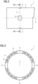
axial plane 7 indicated infig. 2 , thecarrier 2 comprises at least onecarrier material 8 andconductors 9 only coarsely indicated infig. 3 for reasons of simplicity. - An exemplary conductor configuration and pattern is shown in
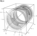
fig. 4 , where it can be seen that theconductors 9 are arranged in two layers, namely aninner layer 10 and anouter layer 11. Conductors of theinner layer 10 form the gradient coils for three physical gradient axes provided by thegradient coil assembly 1. This embodiment, the physical gradient axes 12 perpendicular to thelongitudinal direction 3 have been rotated from their usual orientation along the horizontal direction 4 and thevertical direction 5 by 45 degrees and hence run diagonally. This is due to the positioning of the throughopenings 6, as explained with respect tofigures 5 and 6 . -
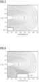
Fig. 5 shows a conventional conductor pattern of a transverse gradient coil in one octant rolled out on the plane spanned by thelongitudinal direction 3 and the circumferential direction. If, now, a through opening, as indicated bybox 13, would be positioned to provide access in a vertical or horizontal direction, it would come to be positioned in an area of very high conductor density and thus current density, in particular maximum current density, such that the efficiency of the gradient coil would be strongly reduced by placing a throughopening 6 here. - However, if the angular positions of the through
openings 6 are rotated 45 degrees against thephysical gradient axis 12, a position of low current density, in particular minimum current density, is reached, and the conductor pattern can, as shown infig. 6 , be designed to maintain a high efficiency of the gradient coils and hence the completegradient coil assembly 1. It is noted that the conductor patterns offig. 5 and fig. 6 only show one gradient coil, while the transverse gradient coil for the perpendiculartransverse gradient axis 12 would have its current density maximum at an angular distance of 90 degrees, that is, the right edge of the octant shown infigures 5 and 6 , such that, actually, the angular position of 45 degrees is the one with minimum current density if all gradient coils are taken into account. - In the magnetic resonance imaging device, a control device may be configured to process acquired magnetic resonance data to use logical gradient axes in the horizontal and
vertical directions 4, 5 instead of the tilted physical gradient axes 12. - The conductors of the
outer layer 11 form active shielding coils, that is, theouter layer 11 represents an electrical shield of thegradient coil assembly 1. These active shielding coils actively counteract the electromagnetic fields of the gradient coils in theinner layer 10 in the radially outward direction, that is, to the main magnet unit, as in principle known from the art. - The active shielding coils and the gradient coils are usually electrically connected, in particular to reduce the inductance of the gradient coil assembly. In this embodiment, the presence of the through
openings 6 is used to provide additional electrical contacting options, in particular an additional surface forconductors 9 electrically connecting thelayers fig. 4 for the leftmost throughopening 6. In other words, theprimary layer 10 and the secondary (shielding)layer 11, in particular gradient coils and active shielding coils associated with respective physical gradient axes 12 are directly electrically connected via the throughopenings 6, in particular their wall surfaces as interlayer connection surfaces. In this manner, the inductance of the gradient coils is reduced, increasing the efficiency of thegradient coil assembly 1. - It is noted that the presence of the through
openings 6 and hence the interlayer connection surfaces can also be taken into account when designing the conductor pattern for thegradient coil assembly 1. -
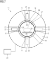
Fig. 7 shows a schematical cross-sectional view of a magneticresonance imaging device 14 according the invention. The magneticresonance imaging device 14 comprises a radially outer, at least predominantly cylindricalmain magnet assembly 15, in which agradient coil assembly 1 and an optional radiofrequency coil assembly 16 are received, leaving an open area forming the patient bore 17. Using a patient table 18, an imaging region of the patient can be positioned in the schematically indicatedhomogeneity volume 19, that is, the field of view of the magneticresonance imaging device 14. - The radio
frequency coil assembly 16 comprises throughopenings 20 aligned with the throughopenings 6 of thegradient coil assembly 1. Furthermore, themain magnet assembly 15 comprisesopenings 21, which do not have to be through openings, aligned with throughopenings therapy devices 22 for the additional diagnostic and/or therapeutic modality to be combined with magnetic resonance imaging, for example x-ray imaging components like an x-ray source, are mounted in at least two of theopenings 21, allowing access to thehomogeneity volume 19 fromvertical direction 5 and from horizontal direction 4. In other embodiments, medical imaging and/ortherapy devices 22 may also be at least partly received in throughopenings 6 and/or 20. In the embodiment shown infig. 7 , radiation and/or particles and/or instruments by the medical imaging and/ortherapy devices 22 may pass through throughopenings homogeneity volume 19. - Since, as explained with respect to
fig. 4 , the physical gradient axes 12 run diagonally, that is at 45 degrees to thevertical direction 5 and the horizontal direction 4, acontrol device 23 of the magneticresonance imaging device 14 is configured to process magnetic resonance data from thesephysical gradient axis 12 to logical gradient axes in the horizontal andvertical directions 4, 5. - Although the present invention has been described in detail with reference to the preferred embodiment, the present invention is not limited by the disclosed examples from which the skilled person is able to derive other variations without departing from the scope of the invention.
Claims (14)
- Magnetic resonance imaging device (14), comprising a gradient coil assembly (1) and a main magnet assembly (15), whereinthe gradient coil assembly (1) comprises a cylindrical carrier (2) with conductors (9) forming three gradient coils associated with three orthogonal physical gradient axes (12),the carrier (2) comprises at least two radial through openings (6) at different angular positions, wherein at least one of the conductors (9) runs through at least one area of the carrier (2) located circumferentially between the through openings (6),characterized in that the main magnet assembly (15) has openings (21) aligned with the through openings (6) of the carrier (2), wherein at least one medical imaging and/or therapy device (22) can be at least partly received in at least one set of aligned openings (6, 21).
- Magnetic resonance imaging device (14) according to claim 1, characterized in that at least one, in particular all, of the through openings (6) is located at an angular position of minimal electric current density.
- Magnetic resonance imaging device (14) according to claim 1 or 2, characterized in that at least one pair of through openings (6), in particular all adjacent through openings (6), are provided at an angular distance of 90 degrees.
- Magnetic resonance imaging device (14) according to one of the preceding claims, characterized in that the angular positions of the through openings (6) are centrally between two physical gradient axes (12) in the axial plane of the through openings (6).
- Magnetic resonance imaging device (14) according to claim 4, characterized in that four through openings (6) are provided, one in each quadrant formed by the two physical gradient axes (12) of the axial plane of the through openings (6) .
- Magnetic resonance imaging device (14) according to one of the preceding claims, characterized in that the gradient coil assembly (1) further comprises at least one electrical shield.
- Magnetic resonance imaging device (14) according to claim 6, characterized in that the shield comprises an active shielding coil arrangement electrically connected to the gradient coils, wherein at least one connection between the shield and the gradient coils runs through at least one of the through openings (6).
- Magnetic resonance imaging device (14) according to one of the preceding claims, characterized in that the conductors (9) are arranged on the carrier (2) according to a pattern generated using the presence of the through openings (6) as a boundary condition, in particular also as providing an interlayer connection surface.
- Magnetic resonance imaging device (14) according to one of the preceding claims, characterized in that the dimensions of the through openings (6) correspond to a field of view of the medical imaging device (22) using the through opening (6) and/or that the through openings (6) extend over an angular interval of 5 to 15 degrees in the circumferential direction.
- Magnetic resonance imaging device (14) according to one of the preceding claims, characterized in that it further comprises a cylindrical radio frequency coil (16) assembly inside the carrier (2), which also has through openings (20) aligned with the through openings (6) of the carrier (2).
- Magnetic resonance imaging device (14) according to one of the preceding claims, characterized in that the at least one medical imaging device (22) comprises an x-ray device for simultaneous acquisition of x-ray imaging data and magnetic resonance imaging data.
- Magnetic resonance imaging device (14) according to one of the preceding claims, characterized in that it further comprises a patient table (18), wherein at least the gradient coil assembly (1) is rotatable around the patient table (18).
- Magnetic resonance imaging device (14) according to claim 12, characterized in that the main magnet assembly (15) and the gradient coil assembly (1), in particular also the radio frequency coil assembly (16), are rotatable together around the patient table (18).
- Magnetic resonance imaging device (14) according to one of the preceding claims, characterized in that it further comprises a control device (23), wherein the two physical gradient axes (12) perpendicular to the longitudinal axis (3) are at angles of 45 degrees each to the horizontal and the vertical direction (4, 5), where the openings align, and the control device is adapted to process acquired magnetic resonance data to a logical vertical and a logical horizontal gradient axis.
Priority Applications (2)
| Application Number | Priority Date | Filing Date | Title |
|---|---|---|---|
| EP21197316.9A EP4152030B1 (en) | 2021-09-17 | 2021-09-17 | Gradient coil assembly for a magnetic resonance imaging device and magnetic resonance imaging device |
| US17/946,367 US12153109B2 (en) | 2021-09-17 | 2022-09-16 | Gradient coil assembly for a magnetic resonance imaging device and magnetic resonance imaging device |
Applications Claiming Priority (1)
| Application Number | Priority Date | Filing Date | Title |
|---|---|---|---|
| EP21197316.9A EP4152030B1 (en) | 2021-09-17 | 2021-09-17 | Gradient coil assembly for a magnetic resonance imaging device and magnetic resonance imaging device |
Publications (2)
| Publication Number | Publication Date |
|---|---|
| EP4152030A1 EP4152030A1 (en) | 2023-03-22 |
| EP4152030B1 true EP4152030B1 (en) | 2024-07-03 |
Family
ID=77821595
Family Applications (1)
| Application Number | Title | Priority Date | Filing Date |
|---|---|---|---|
| EP21197316.9A Active EP4152030B1 (en) | 2021-09-17 | 2021-09-17 | Gradient coil assembly for a magnetic resonance imaging device and magnetic resonance imaging device |
Country Status (2)
| Country | Link |
|---|---|
| US (1) | US12153109B2 (en) |
| EP (1) | EP4152030B1 (en) |
Families Citing this family (1)
| Publication number | Priority date | Publication date | Assignee | Title |
|---|---|---|---|---|
| EP4328610B1 (en) | 2022-08-25 | 2026-06-10 | Siemens Healthineers AG | Gradient coil unit for interventional mr imaging |
Family Cites Families (9)
| Publication number | Priority date | Publication date | Assignee | Title |
|---|---|---|---|---|
| US5304933A (en) * | 1991-08-01 | 1994-04-19 | General Electric Company | Surgical local gradient coil |
| CA2131705C (en) | 1992-03-09 | 2008-10-21 | Aaron G. Filler | Image neurography and diffusion anisotropy imaging |
| EP0737319B1 (en) * | 1993-06-04 | 1998-04-22 | University of Washington | Focal neurographic magnetic resonance imaging system |
| DE19829298C2 (en) * | 1998-06-30 | 2000-05-31 | Siemens Ag | Gradient coil system for a magnetic resonance imaging device |
| GB2427479B (en) * | 2005-06-22 | 2007-11-14 | Siemens Magnet Technology Ltd | Particle Radiation Therapy Equipment and method for performing particle radiation therapy |
| DE102007054324B4 (en) * | 2007-11-14 | 2009-10-22 | Siemens Ag | Device for radiotherapy under image monitoring |
| JP5224421B2 (en) * | 2009-03-12 | 2013-07-03 | 独立行政法人放射線医学総合研究所 | Open PET / MRI combined machine |
| EP3160585B1 (en) * | 2014-06-27 | 2019-02-27 | Koninklijke Philips N.V. | Charged particle beam therapy and magnetic resonance imaging |
| EP3327457A1 (en) * | 2016-11-23 | 2018-05-30 | Siemens Healthcare GmbH | Medical imaging system comprising a magnet unit and a radiation unit |
-
2021
- 2021-09-17 EP EP21197316.9A patent/EP4152030B1/en active Active
-
2022
- 2022-09-16 US US17/946,367 patent/US12153109B2/en active Active
Also Published As
| Publication number | Publication date |
|---|---|
| US12153109B2 (en) | 2024-11-26 |
| US20230086830A1 (en) | 2023-03-23 |
| EP4152030A1 (en) | 2023-03-22 |
Similar Documents
| Publication | Publication Date | Title |
|---|---|---|
| TWI743481B (en) | B magnet methods and apparatus for a magnetic resonance imaging system | |
| AU2017200361B2 (en) | Method and apparatus for shielding a linear accelerator and a magnetic resonance imaging device from each other | |
| EP2135107B1 (en) | Pet/mri hybrid system using a split gradient coil | |
| EP1893290B1 (en) | Particle radiation therapy equipment comprising magnetic resonance imaging means | |
| JP5715116B2 (en) | Mosaic shim coil for magnetic resonance system | |
| EP0679900B1 (en) | Pancake MRI magnet | |
| CA2728111C (en) | Radiation therapy system | |
| US9669237B2 (en) | Combined MRI and radiation therapy equipment | |
| CN105283934B (en) | Gradient coil assembly with outer coil comprising aluminum | |
| JP5468546B2 (en) | Control of magnetic field uniformity in a movable MRI scan system | |
| US12153109B2 (en) | Gradient coil assembly for a magnetic resonance imaging device and magnetic resonance imaging device | |
| US8198893B2 (en) | Method to design a gradient coil, method to manufacture a gradient coil, gradient coil, magnetic resonance apparatus and combined PET-MR system | |
| US8598878B2 (en) | Inductor assembly for a magnetic resonance imaging system | |
| US20240219494A1 (en) | Magnetic resonance imaging systems and components thereof | |
| JP5069471B2 (en) | Planar RF resonator for open MRI systems | |
| US20210103019A1 (en) | Open bore magnet for mri guided radiotherapy system | |
| CN221905435U (en) | Radiation therapy system | |
| US20240004003A1 (en) | Magnetic resonance imaging devices and radiation therapy systems including the magnetic resonance imaging devices | |
| US12449493B2 (en) | Gradient coil unit for interventional MR imaging | |
| US12099104B2 (en) | Passive shield for magnetic resonance imaging gradient coils | |
| US11255935B2 (en) | Gradient shield coil with meandering winding for a magnetic resonance imaging apparatus | |
| JPH0739539A (en) | High frequency coil used in magnetic resonance inspection system | |
| US20220031164A1 (en) | Mri-ct system and methods for sequentially imaging | |
| CN117298464A (en) | Magnetic resonance equipment and treatment systems including magnetic resonance equipment |
Legal Events
| Date | Code | Title | Description |
|---|---|---|---|
| PUAI | Public reference made under article 153(3) epc to a published international application that has entered the european phase |
Free format text: ORIGINAL CODE: 0009012 |
|
| STAA | Information on the status of an ep patent application or granted ep patent |
Free format text: STATUS: THE APPLICATION HAS BEEN PUBLISHED |
|
| AK | Designated contracting states |
Kind code of ref document: A1 Designated state(s): AL AT BE BG CH CY CZ DE DK EE ES FI FR GB GR HR HU IE IS IT LI LT LU LV MC MK MT NL NO PL PT RO RS SE SI SK SM TR |
|
| STAA | Information on the status of an ep patent application or granted ep patent |
Free format text: STATUS: REQUEST FOR EXAMINATION WAS MADE |
|
| 17P | Request for examination filed |
Effective date: 20230918 |
|
| RBV | Designated contracting states (corrected) |
Designated state(s): AL AT BE BG CH CY CZ DE DK EE ES FI FR GB GR HR HU IE IS IT LI LT LU LV MC MK MT NL NO PL PT RO RS SE SI SK SM TR |
|
| RAP1 | Party data changed (applicant data changed or rights of an application transferred) |
Owner name: SIEMENS HEALTHINEERS AG |
|
| GRAP | Despatch of communication of intention to grant a patent |
Free format text: ORIGINAL CODE: EPIDOSNIGR1 |
|
| STAA | Information on the status of an ep patent application or granted ep patent |
Free format text: STATUS: GRANT OF PATENT IS INTENDED |
|
| RIC1 | Information provided on ipc code assigned before grant |
Ipc: A61B 6/40 20240101ALN20240201BHEP Ipc: A61B 6/00 20060101ALN20240201BHEP Ipc: G01R 33/34 20060101ALN20240201BHEP Ipc: G01R 33/421 20060101ALN20240201BHEP Ipc: A61B 6/03 20060101ALI20240201BHEP Ipc: G01R 33/48 20060101ALI20240201BHEP Ipc: G01R 33/385 20060101AFI20240201BHEP |
|
| INTG | Intention to grant announced |
Effective date: 20240223 |
|
| INTG | Intention to grant announced |
Effective date: 20240223 |
|
| GRAS | Grant fee paid |
Free format text: ORIGINAL CODE: EPIDOSNIGR3 |
|
| GRAA | (expected) grant |
Free format text: ORIGINAL CODE: 0009210 |
|
| STAA | Information on the status of an ep patent application or granted ep patent |
Free format text: STATUS: THE PATENT HAS BEEN GRANTED |
|
| AK | Designated contracting states |
Kind code of ref document: B1 Designated state(s): AL AT BE BG CH CY CZ DE DK EE ES FI FR GB GR HR HU IE IS IT LI LT LU LV MC MK MT NL NO PL PT RO RS SE SI SK SM TR |
|
| REG | Reference to a national code |
Ref country code: CH Ref legal event code: EP |
|
| REG | Reference to a national code |
Ref country code: DE Ref legal event code: R096 Ref document number: 602021015059 Country of ref document: DE |
|
| REG | Reference to a national code |
Ref country code: LT Ref legal event code: MG9D |
|
| REG | Reference to a national code |
Ref country code: NL Ref legal event code: MP Effective date: 20240703 |
|
| PG25 | Lapsed in a contracting state [announced via postgrant information from national office to epo] |
Ref country code: PT Free format text: LAPSE BECAUSE OF FAILURE TO SUBMIT A TRANSLATION OF THE DESCRIPTION OR TO PAY THE FEE WITHIN THE PRESCRIBED TIME-LIMIT Effective date: 20241104 |
|
| REG | Reference to a national code |
Ref country code: AT Ref legal event code: MK05 Ref document number: 1700365 Country of ref document: AT Kind code of ref document: T Effective date: 20240703 |
|
| PG25 | Lapsed in a contracting state [announced via postgrant information from national office to epo] |
Ref country code: NL Free format text: LAPSE BECAUSE OF FAILURE TO SUBMIT A TRANSLATION OF THE DESCRIPTION OR TO PAY THE FEE WITHIN THE PRESCRIBED TIME-LIMIT Effective date: 20240703 |
|
| PG25 | Lapsed in a contracting state [announced via postgrant information from national office to epo] |
Ref country code: PT Free format text: LAPSE BECAUSE OF FAILURE TO SUBMIT A TRANSLATION OF THE DESCRIPTION OR TO PAY THE FEE WITHIN THE PRESCRIBED TIME-LIMIT Effective date: 20241104 Ref country code: NL Free format text: LAPSE BECAUSE OF FAILURE TO SUBMIT A TRANSLATION OF THE DESCRIPTION OR TO PAY THE FEE WITHIN THE PRESCRIBED TIME-LIMIT Effective date: 20240703 |
|
| PG25 | Lapsed in a contracting state [announced via postgrant information from national office to epo] |
Ref country code: NO Free format text: LAPSE BECAUSE OF FAILURE TO SUBMIT A TRANSLATION OF THE DESCRIPTION OR TO PAY THE FEE WITHIN THE PRESCRIBED TIME-LIMIT Effective date: 20241003 |
|
| PG25 | Lapsed in a contracting state [announced via postgrant information from national office to epo] |
Ref country code: FI Free format text: LAPSE BECAUSE OF FAILURE TO SUBMIT A TRANSLATION OF THE DESCRIPTION OR TO PAY THE FEE WITHIN THE PRESCRIBED TIME-LIMIT Effective date: 20240703 Ref country code: GR Free format text: LAPSE BECAUSE OF FAILURE TO SUBMIT A TRANSLATION OF THE DESCRIPTION OR TO PAY THE FEE WITHIN THE PRESCRIBED TIME-LIMIT Effective date: 20241004 Ref country code: PL Free format text: LAPSE BECAUSE OF FAILURE TO SUBMIT A TRANSLATION OF THE DESCRIPTION OR TO PAY THE FEE WITHIN THE PRESCRIBED TIME-LIMIT Effective date: 20240703 |
|
| PG25 | Lapsed in a contracting state [announced via postgrant information from national office to epo] |
Ref country code: BG Free format text: LAPSE BECAUSE OF FAILURE TO SUBMIT A TRANSLATION OF THE DESCRIPTION OR TO PAY THE FEE WITHIN THE PRESCRIBED TIME-LIMIT Effective date: 20240703 |
|
| PG25 | Lapsed in a contracting state [announced via postgrant information from national office to epo] |
Ref country code: LV Free format text: LAPSE BECAUSE OF FAILURE TO SUBMIT A TRANSLATION OF THE DESCRIPTION OR TO PAY THE FEE WITHIN THE PRESCRIBED TIME-LIMIT Effective date: 20240703 |
|
| PG25 | Lapsed in a contracting state [announced via postgrant information from national office to epo] |
Ref country code: IS Free format text: LAPSE BECAUSE OF FAILURE TO SUBMIT A TRANSLATION OF THE DESCRIPTION OR TO PAY THE FEE WITHIN THE PRESCRIBED TIME-LIMIT Effective date: 20241103 Ref country code: AT Free format text: LAPSE BECAUSE OF FAILURE TO SUBMIT A TRANSLATION OF THE DESCRIPTION OR TO PAY THE FEE WITHIN THE PRESCRIBED TIME-LIMIT Effective date: 20240703 |
|
| PG25 | Lapsed in a contracting state [announced via postgrant information from national office to epo] |
Ref country code: HR Free format text: LAPSE BECAUSE OF FAILURE TO SUBMIT A TRANSLATION OF THE DESCRIPTION OR TO PAY THE FEE WITHIN THE PRESCRIBED TIME-LIMIT Effective date: 20240703 Ref country code: CZ Free format text: LAPSE BECAUSE OF FAILURE TO SUBMIT A TRANSLATION OF THE DESCRIPTION OR TO PAY THE FEE WITHIN THE PRESCRIBED TIME-LIMIT Effective date: 20240703 |
|
| PG25 | Lapsed in a contracting state [announced via postgrant information from national office to epo] |
Ref country code: RS Free format text: LAPSE BECAUSE OF FAILURE TO SUBMIT A TRANSLATION OF THE DESCRIPTION OR TO PAY THE FEE WITHIN THE PRESCRIBED TIME-LIMIT Effective date: 20241003 Ref country code: ES Free format text: LAPSE BECAUSE OF FAILURE TO SUBMIT A TRANSLATION OF THE DESCRIPTION OR TO PAY THE FEE WITHIN THE PRESCRIBED TIME-LIMIT Effective date: 20240703 |
|
| PG25 | Lapsed in a contracting state [announced via postgrant information from national office to epo] |
Ref country code: RS Free format text: LAPSE BECAUSE OF FAILURE TO SUBMIT A TRANSLATION OF THE DESCRIPTION OR TO PAY THE FEE WITHIN THE PRESCRIBED TIME-LIMIT Effective date: 20241003 Ref country code: PL Free format text: LAPSE BECAUSE OF FAILURE TO SUBMIT A TRANSLATION OF THE DESCRIPTION OR TO PAY THE FEE WITHIN THE PRESCRIBED TIME-LIMIT Effective date: 20240703 Ref country code: NO Free format text: LAPSE BECAUSE OF FAILURE TO SUBMIT A TRANSLATION OF THE DESCRIPTION OR TO PAY THE FEE WITHIN THE PRESCRIBED TIME-LIMIT Effective date: 20241003 Ref country code: LV Free format text: LAPSE BECAUSE OF FAILURE TO SUBMIT A TRANSLATION OF THE DESCRIPTION OR TO PAY THE FEE WITHIN THE PRESCRIBED TIME-LIMIT Effective date: 20240703 Ref country code: IS Free format text: LAPSE BECAUSE OF FAILURE TO SUBMIT A TRANSLATION OF THE DESCRIPTION OR TO PAY THE FEE WITHIN THE PRESCRIBED TIME-LIMIT Effective date: 20241103 Ref country code: HR Free format text: LAPSE BECAUSE OF FAILURE TO SUBMIT A TRANSLATION OF THE DESCRIPTION OR TO PAY THE FEE WITHIN THE PRESCRIBED TIME-LIMIT Effective date: 20240703 Ref country code: GR Free format text: LAPSE BECAUSE OF FAILURE TO SUBMIT A TRANSLATION OF THE DESCRIPTION OR TO PAY THE FEE WITHIN THE PRESCRIBED TIME-LIMIT Effective date: 20241004 Ref country code: FI Free format text: LAPSE BECAUSE OF FAILURE TO SUBMIT A TRANSLATION OF THE DESCRIPTION OR TO PAY THE FEE WITHIN THE PRESCRIBED TIME-LIMIT Effective date: 20240703 Ref country code: ES Free format text: LAPSE BECAUSE OF FAILURE TO SUBMIT A TRANSLATION OF THE DESCRIPTION OR TO PAY THE FEE WITHIN THE PRESCRIBED TIME-LIMIT Effective date: 20240703 Ref country code: CZ Free format text: LAPSE BECAUSE OF FAILURE TO SUBMIT A TRANSLATION OF THE DESCRIPTION OR TO PAY THE FEE WITHIN THE PRESCRIBED TIME-LIMIT Effective date: 20240703 Ref country code: BG Free format text: LAPSE BECAUSE OF FAILURE TO SUBMIT A TRANSLATION OF THE DESCRIPTION OR TO PAY THE FEE WITHIN THE PRESCRIBED TIME-LIMIT Effective date: 20240703 Ref country code: AT Free format text: LAPSE BECAUSE OF FAILURE TO SUBMIT A TRANSLATION OF THE DESCRIPTION OR TO PAY THE FEE WITHIN THE PRESCRIBED TIME-LIMIT Effective date: 20240703 |
|
| REG | Reference to a national code |
Ref country code: DE Ref legal event code: R097 Ref document number: 602021015059 Country of ref document: DE |
|
| PG25 | Lapsed in a contracting state [announced via postgrant information from national office to epo] |
Ref country code: DK Free format text: LAPSE BECAUSE OF FAILURE TO SUBMIT A TRANSLATION OF THE DESCRIPTION OR TO PAY THE FEE WITHIN THE PRESCRIBED TIME-LIMIT Effective date: 20240703 Ref country code: RO Free format text: LAPSE BECAUSE OF FAILURE TO SUBMIT A TRANSLATION OF THE DESCRIPTION OR TO PAY THE FEE WITHIN THE PRESCRIBED TIME-LIMIT Effective date: 20240703 Ref country code: SM Free format text: LAPSE BECAUSE OF FAILURE TO SUBMIT A TRANSLATION OF THE DESCRIPTION OR TO PAY THE FEE WITHIN THE PRESCRIBED TIME-LIMIT Effective date: 20240703 |
|
| PG25 | Lapsed in a contracting state [announced via postgrant information from national office to epo] |
Ref country code: EE Free format text: LAPSE BECAUSE OF FAILURE TO SUBMIT A TRANSLATION OF THE DESCRIPTION OR TO PAY THE FEE WITHIN THE PRESCRIBED TIME-LIMIT Effective date: 20240703 Ref country code: MC Free format text: LAPSE BECAUSE OF FAILURE TO SUBMIT A TRANSLATION OF THE DESCRIPTION OR TO PAY THE FEE WITHIN THE PRESCRIBED TIME-LIMIT Effective date: 20240703 |
|
| PG25 | Lapsed in a contracting state [announced via postgrant information from national office to epo] |
Ref country code: IT Free format text: LAPSE BECAUSE OF FAILURE TO SUBMIT A TRANSLATION OF THE DESCRIPTION OR TO PAY THE FEE WITHIN THE PRESCRIBED TIME-LIMIT Effective date: 20240703 Ref country code: SK Free format text: LAPSE BECAUSE OF FAILURE TO SUBMIT A TRANSLATION OF THE DESCRIPTION OR TO PAY THE FEE WITHIN THE PRESCRIBED TIME-LIMIT Effective date: 20240703 |
|
| REG | Reference to a national code |
Ref country code: CH Ref legal event code: PL |
|
| PLBE | No opposition filed within time limit |
Free format text: ORIGINAL CODE: 0009261 |
|
| STAA | Information on the status of an ep patent application or granted ep patent |
Free format text: STATUS: NO OPPOSITION FILED WITHIN TIME LIMIT |
|
| PG25 | Lapsed in a contracting state [announced via postgrant information from national office to epo] |
Ref country code: LU Free format text: LAPSE BECAUSE OF NON-PAYMENT OF DUE FEES Effective date: 20240917 |
|
| 26N | No opposition filed |
Effective date: 20250404 |
|
| REG | Reference to a national code |
Ref country code: BE Ref legal event code: MM Effective date: 20240930 |
|
| PG25 | Lapsed in a contracting state [announced via postgrant information from national office to epo] |
Ref country code: BE Free format text: LAPSE BECAUSE OF NON-PAYMENT OF DUE FEES Effective date: 20240930 |
|
| PG25 | Lapsed in a contracting state [announced via postgrant information from national office to epo] |
Ref country code: CH Free format text: LAPSE BECAUSE OF NON-PAYMENT OF DUE FEES Effective date: 20240930 |
|
| PG25 | Lapsed in a contracting state [announced via postgrant information from national office to epo] |
Ref country code: IE Free format text: LAPSE BECAUSE OF NON-PAYMENT OF DUE FEES Effective date: 20240917 |
|
| PG25 | Lapsed in a contracting state [announced via postgrant information from national office to epo] |
Ref country code: SE Free format text: LAPSE BECAUSE OF FAILURE TO SUBMIT A TRANSLATION OF THE DESCRIPTION OR TO PAY THE FEE WITHIN THE PRESCRIBED TIME-LIMIT Effective date: 20240703 |
|
| PGFP | Annual fee paid to national office [announced via postgrant information from national office to epo] |
Ref country code: FR Payment date: 20250915 Year of fee payment: 5 |
|
| PGFP | Annual fee paid to national office [announced via postgrant information from national office to epo] |
Ref country code: DE Payment date: 20251120 Year of fee payment: 5 |
|
| PGFP | Annual fee paid to national office [announced via postgrant information from national office to epo] |
Ref country code: GB Payment date: 20251002 Year of fee payment: 5 |
|
| PG25 | Lapsed in a contracting state [announced via postgrant information from national office to epo] |
Ref country code: CY Free format text: LAPSE BECAUSE OF FAILURE TO SUBMIT A TRANSLATION OF THE DESCRIPTION OR TO PAY THE FEE WITHIN THE PRESCRIBED TIME-LIMIT; INVALID AB INITIO Effective date: 20210917 |
|
| PG25 | Lapsed in a contracting state [announced via postgrant information from national office to epo] |
Ref country code: HU Free format text: LAPSE BECAUSE OF FAILURE TO SUBMIT A TRANSLATION OF THE DESCRIPTION OR TO PAY THE FEE WITHIN THE PRESCRIBED TIME-LIMIT; INVALID AB INITIO Effective date: 20210917 |
|
| PG25 | Lapsed in a contracting state [announced via postgrant information from national office to epo] |
Ref country code: TR Free format text: LAPSE BECAUSE OF FAILURE TO SUBMIT A TRANSLATION OF THE DESCRIPTION OR TO PAY THE FEE WITHIN THE PRESCRIBED TIME-LIMIT Effective date: 20240703 |
|
| PG25 | Lapsed in a contracting state [announced via postgrant information from national office to epo] |
Ref country code: SI Free format text: LAPSE BECAUSE OF FAILURE TO SUBMIT A TRANSLATION OF THE DESCRIPTION OR TO PAY THE FEE WITHIN THE PRESCRIBED TIME-LIMIT Effective date: 20240703 |
|
| PG25 | Lapsed in a contracting state [announced via postgrant information from national office to epo] |
Ref country code: LT Free format text: LAPSE BECAUSE OF FAILURE TO SUBMIT A TRANSLATION OF THE DESCRIPTION OR TO PAY THE FEE WITHIN THE PRESCRIBED TIME-LIMIT Effective date: 20240703 |